
Abstract
This paper mainly focuses on the remarkable transient vibration and underwater acoustic radiation when the underwater vehicle changes direction or depth, and a short time Fourier transform signal processing method to evaluate transient vibration and acoustic radiation of steering engine is provided in this paper. Based on the vibration test of the 1:1 experimental scaffold of the steering engine for an underwater vehicle, the transient maximum excitation forces acting at the contact points between steering engine and experimental scaffold are calculated indirectly by the least square method of load identification in frequency domain and the short time Fourier transform signal processing method. The accuracy and feasibility of results are verified. In addition, taking excitation forces as an approximate input, the numerical solution of transient acoustic radiation for a cylindrical shell with ribs of the steering engine room, based on elastic shell theory and fluid–structure interaction theory, is presented. In the simulation, the steering engine room of the underwater vehicle is simplified into a cylindrical shell with two simply supported tips, because a cylindrical shell with ribs is the basic structure-borne used in underwater vehicles. The results show that transient acoustic radiation of the tested steering engine is higher than allowable value, while the evaluation results of another electric steering engine without retarder are suitable.
Keywords
Introduction
With the development of vibration noise reduction technology, the steady-state acoustic radiation of underwater vehicle is getting smaller, while the transient acoustic radiation becomes the main exposure source for an underwater vehicle. The steady-state sailing could be changed which happens when an underwater vehicle changes direction or depth by the steering engine, meanwhile generating remarkable transient vibration and underwater acoustic radiation; therefore, it is necessary to evaluate the source vibration characteristic of steering engine before it is installed. However, the traditional evaluation method is not suitable to analyze the transient vibration and underwater acoustic radiation. In terms of choice of the steering engine and underwater survival security for an underwater vehicle, it is of great significance to present an evaluation method for transient vibration and underwater acoustic radiation.
The transient vibration and acoustic radiation are characterized by short time, large energy and difficult evaluation, which can considerably reduce the acoustic stealth performance of an underwater vehicle. A lot of work has been reported in the literature where a beam, a plate, or a cylinder shell model were included, but the research on remarkable transient vibration and acoustic radiation when the underwater vehicle changes direction or depth can hardly be found in them. The unmanned landing module for space exploration missions was simplified as an elastic beam from decelerating boundaries, and transient response was analyzed. 1 It was shown that passive attenuation of peak transient deceleration was possible by coupling the beam to a tuned one-degree-of-freedom oscillator. Li et al. 2 presented the method of reverberation ray matrix to research the transient wave propagation and early short-time transient responses of the stiffened laminated composite plates subjected to impact loads. Geng et al. 3 reconstructed the transient pressure field radiated by an impacted plate and the normal acceleration of the plate by time domain plane wave superposition method. An experiment of a clamped rectangular steel plate impacted by a steel ball was presented to validate the extended method was effective in visualizing the transient vibration and sound radiation of an impacted plate. Ou and Mak 4 reviewed commonly used approaches to the analysis of structural transient vibration and sound radiation. A general process for solving this type of problem was presented together with suggestions for future work in this field. Hasheminejad and Mousavi-Akbarzadeh5,6 investigated transient acoustic radiation from an eccentric sphere and an eccentric hollow cylinder by utilizing the 3D time-domain linear acoustic wave equation, the Navier’s equations of transient elastodynamics, the separation of parameters in spherical coordinates, in conjunction with a modified form of the addition theorem for spherical vector wave functions. Maury and Filippi 7 dealt with the response of an axisymmetrical shell is composed of a cylindrical shell closed by two hemispherical shells to a transient incident wave, and a new statement of the basic equations and a numerical method based on polynomial approximations was presented. Li and Hua 8 calculated the transient vibration characteristics of the laminated composite cylindrical shells with infinite length, caused by the pressure wave from an underwater shock by the reflected-afterflow virtual-source (RAVS) method. Caresta et al. 9 predicted the transient response of a structure at the driving point following an impact or a shock loading based on random point process theory. The theory was applied to a wide range of structures and the results were experimentally verified for the case of a rigid object hitting a beam, a plate, a thin and a thick cylinder, and for the impact between two cylinders. Zhang et al. 10 investigated the transient noise induced by vehicle–bridge coupling vibration by employing the hybrid finite element method and boundary element method. The precision of the proposed method was validated by comparing the numerical results to the onsite measurements of a steel girder–plate bridge in service. Above all, the studies on the transient vibration and acoustic radiation were mainly concentrated on shock or impact problems of beam or plate frame models, and the duration of the excitation force which generates a high vibration is extremely short. Although the duration time is a little longer when an underwater vehicle changes direction or depth by the steering engine, the vibration status of the vehicle is changed severely, and therefore it can be still regarded as transient vibration and acoustic radiation; however, there is still no further research on it.
Excitation forces are often needed for machinery noise evaluation. Zhou and Sun 11 obtained the bearing force by solving the transmission system dynamic model, and the bearing force was taken as the excitation of the gearbox, so the steady dynamic response and noise radiation generated by a gear reducer were demonstrated. But in engineering practice, it is difficult to measure the external loads acting on the structure directly due to the limitation of actual environment. Therefore, the load identification technology is needed to indirectly evaluate the excitation force of the equipment. Load identification methods include frequency domain method and time domain method. Time domain method started relatively late, by contrast, frequency domain method is relatively mature, and has made great progress.
In the late 1970s, dynamic loads of the main shaft of helicopter were evaluated indirectly by measuring the frequency response function matrix and vector of the acceleration response.12,13 Okubo et al. 14 summed up the three methods of load identification that include the direct inverse method, the least square method and the modal coordinate transformation method. O’Callahan and Piergentili 15 identified the loads by frequency response function inversion and studied the influence of load position on the error by the singular value decomposition method. Their results showed that load identification results were good if presupposed load position contained the actual load position, not vice versa. Yap and Gibbs16,17 and Yap and Su 18 presented the reciprocity method to evaluate the force and moment acting at the contact points between the equipment and the support structure indirectly. The drawback that previous indirect measurement could only be used for elastic installation was overcome by this method.
This paper mainly focuses on the remarkable transient vibration and underwater acoustic radiation, when the underwater vehicle changes direction or depth. Through the vibration test of the steering gear, the transient maximum excitation force at the contact point between the steering gear and the experimental support is calculated by using the short time Fourier transform (STFT) due to the non-stationary feature of the excitation force. Taking excitation forces as an approximate input, the numerical solution of transient acoustic radiation for a cylindrical shell with ribs of the steering engine room is presented. It is found that transient acoustic radiation of the tested steering engine is higher than allowable value, while the evaluation results of another electric steering engine without retarder are suitable. An STFT signal processing method to evaluate transient vibration and acoustic radiation of steering engine is provided in this paper.
Evaluation of excitation force on the steering engine
The least square method is used in this paper because it is more accurate. The least square method is a complement to the direct inverse method, and the number of response points is more than that of excitation points so that the least square solution whose error is smaller can be obtained.
Evaluation process of source excitation force
The details of estimating process are shown as follows:
The frequency response function should be measured, and frequency response function matrix tested is expressed as Vibration response of each response point should be measured when the equipment is in a steady state. Each response point should be the same with each measured point by frequency response function. And a part of the response points considered as the acceleration response vector Solution of the excitation force.
The relationship between excitation force and response can be expressed as

According to equation (1),

Equation (2) can be used to approximately calculate the inverse matrix. However, a small amount of response points cannot reflect the system completely, and it is impracticable to improve the accuracy using more response data because of the complexity of mechanical structure.
If the number of response points is more than that of excitation points in the frequency response function matrix, then

At this time, a set of

According to the definition of the residual error

Differentiating for


If the frequency response function matrix and vibration response of equipment are known, the excitation forces acting at the contact points between steering engine and experimental scaffold can be evaluated by equation (8); however, the excitation force estimation error is a little larger, due to the ill-posed problem during frequency response function matrix inversion. Therefore, a truncated singular value method 19 is used to treat this problem in this paper.
Validation of the excitation force
Frequency response function matrix and the acceleration response vector of the remaining response points are selected. The acceleration response can be calculated by substituting the excitation force vector
Vibration test of steering engine
Measurement of the frequency response function
Firstly, the locations of the excitation points and response points are selected. Excitation points should be at the foot position of machine, and the number of response points should be more than excitation points, so that the least square method could be applied. The experimental scaffold of steering engine is shown in Figure 1.
The four excitation points at the foot of steering engine are denoted as I, II, III, IV, respectively, response points are denoted as 1, 2, 3, 4, respectively, and other response points are denoted as 5, 6, 7, 8, as shown in Figure 2.
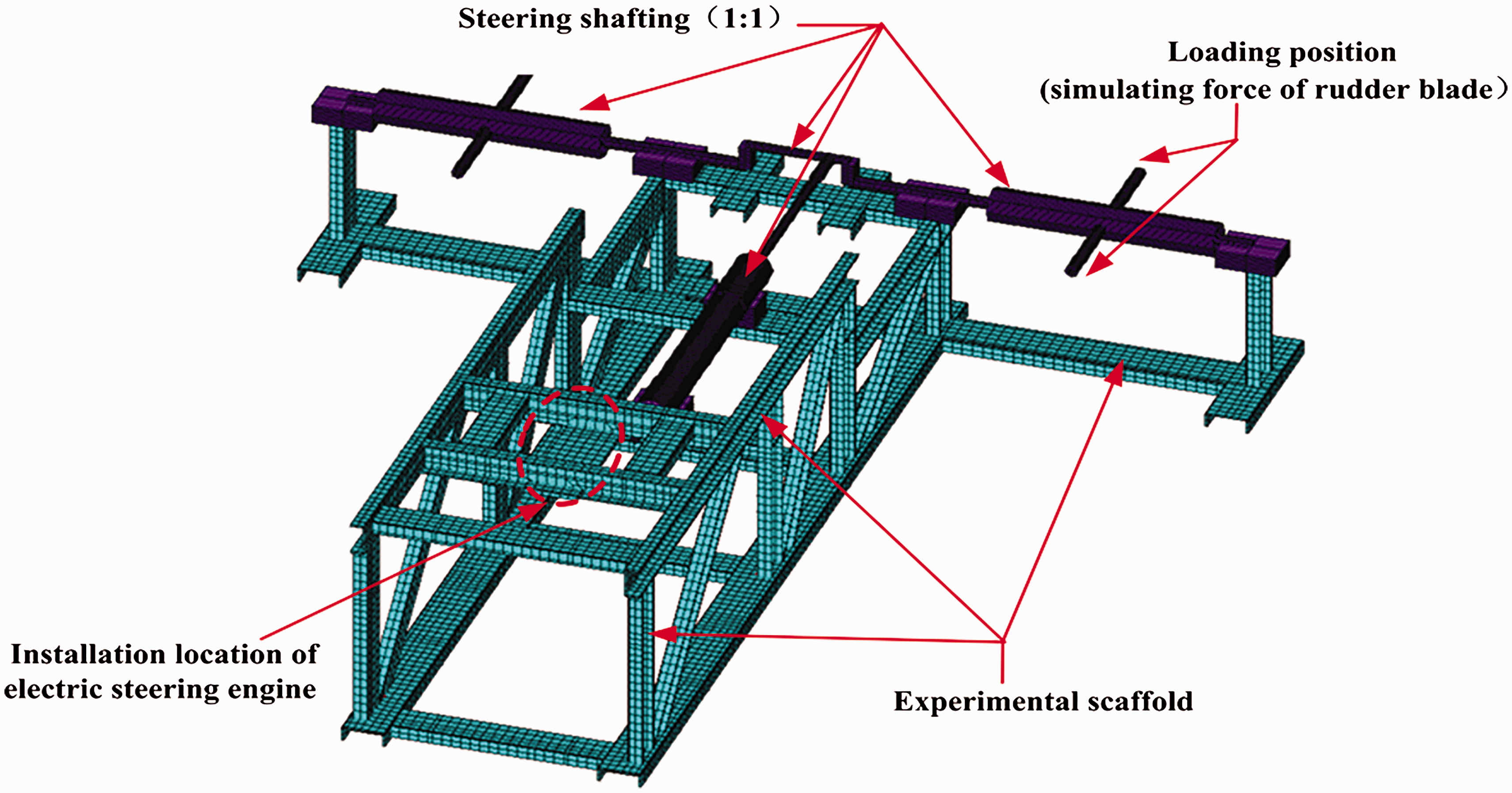
The 1:1 experimental scaffold of steering engine.
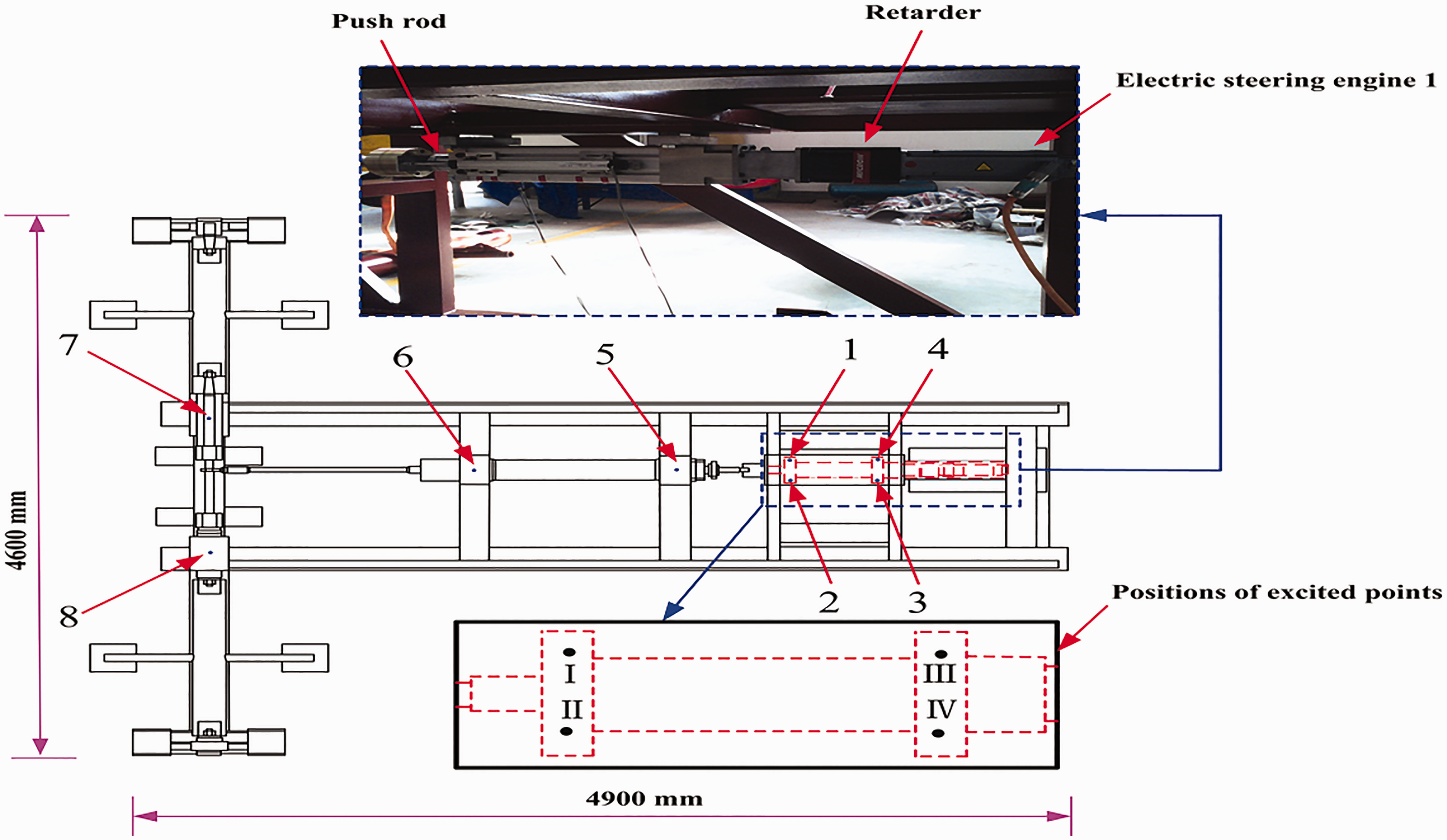
The layout of test points.
Measurement steps of frequency response function are as follows:
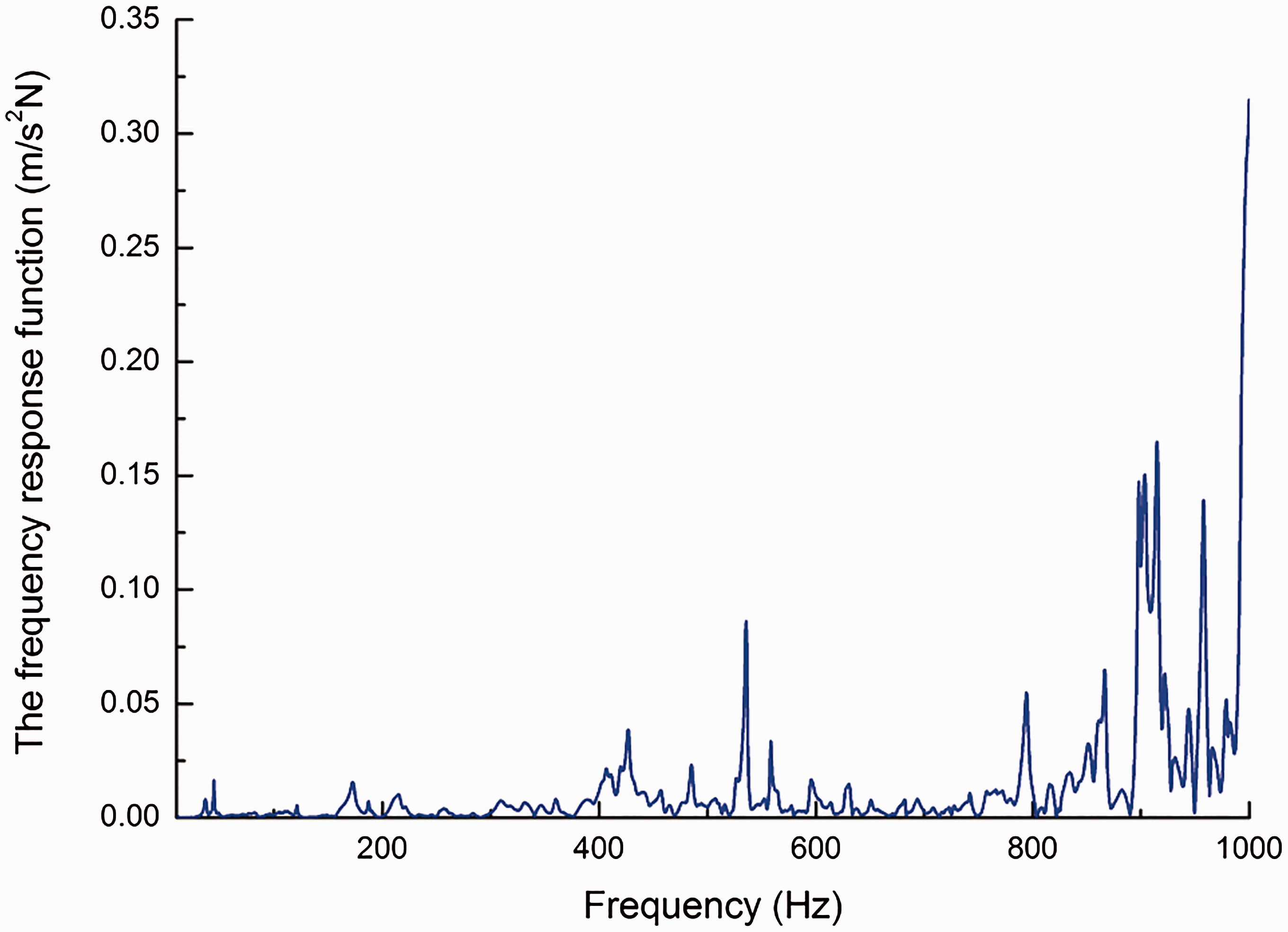
The acceleration sensors are decorated at each measuring point, and the sensors and the multi-channel data collector are connected with program-controlled amplifier. The serial number of each sensor corresponding with connection channel should be recorded. Excitation point I is knocked by a force hammer, as shown in Figure 3. this excitation point is hit 10 times, and then the acceleration sensor signal is measured and recorded; at the same time, the hammer excitation force signal is recorded. According to the step (2), excitation points II, III, IV are knocked, respectively, and excitation force signal and the acceleration sensor signal of the eight measured points should be recorded. The frequency response function of the system is obtained by processing the measured data, as shown in Figure 4.
Signal processing
The vibration response of each measured point is recorded when the steering is running. In this paper, only the test results under the conditions of maximum speed (10°/s) and rudder blades’ loads are used to calculate the excitation force. And the detailed testing results of the response point 5 will be discussed in this paper.
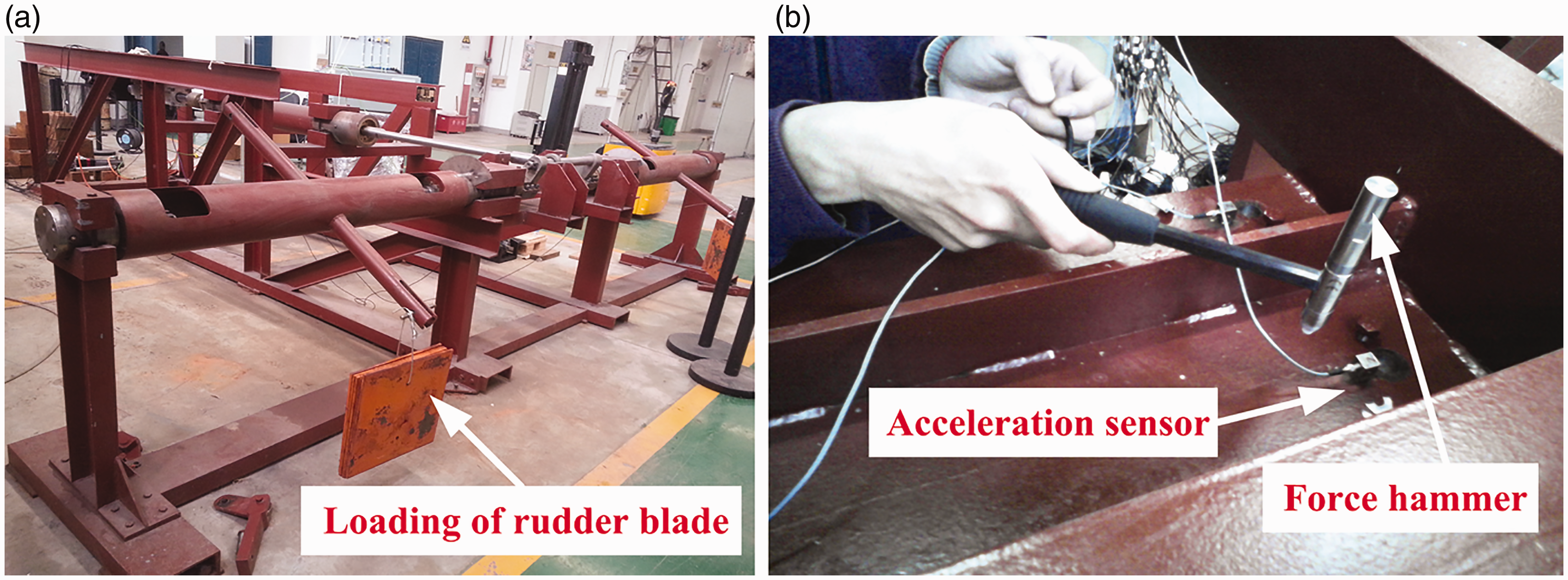
The on-site vibration test of experimental scaffold.
It can be seen from Figure 5 that operating process of steering engine is unstable, and the signal of significant amplitude mainly occurs from the sixth second to the ninth second. The time-varying non-stationary signals cannot be analyzed well by the classic signal processing technology; therefore, it is necessary to study the global and localization characteristics in the time domain and frequency domain for non-stationary signals in order to evaluate the global and localization performances, which cannot be achieved only by the time domain or frequency domain analysis.
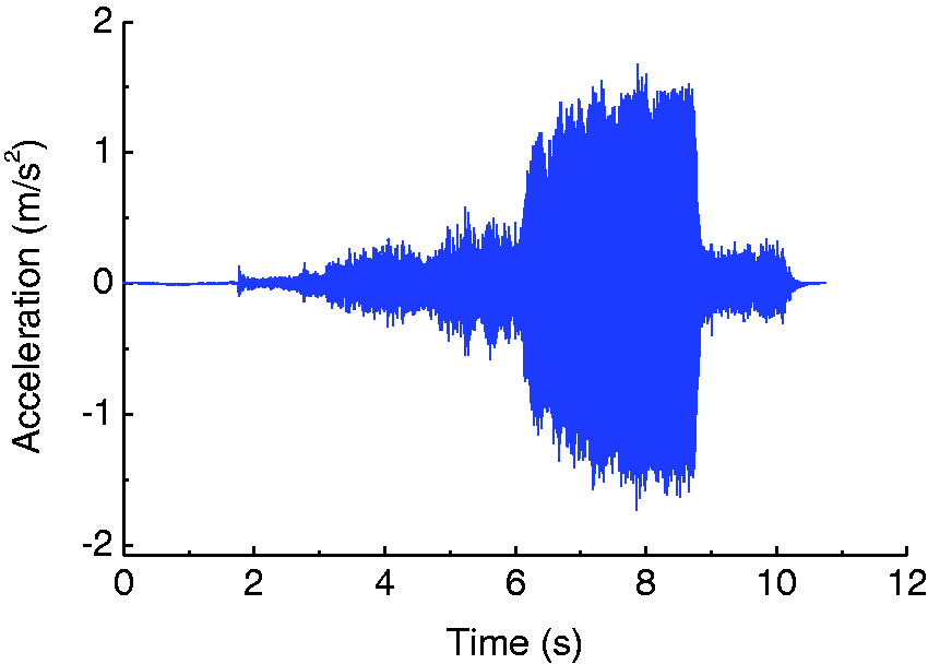
The acceleration signal of point 5.
The STFT is widely used in the analysis of non-stationary signal. In this method, non-stationary signal is composed of a series of short stationary signals, and short-time characteristics are available by window function. The signal in window is assumed to be quasi-stationary, and then, the time–frequency spectrum of the signal is available by Fourier transform of each section of the signal. For a given non-stationary signal, a new signal is defined through the window function

The signal is the function of parameter

Because the characteristics of a period of time of the original signal
In this paper, STFT method is used, and then the elements in response vector

The time–frequency spectrum of the measurement signal after short-time Fourier transform is shown in Figure 6. It shows the time–frequency vibration characteristics of the whole process: (1) During 1–6 s, the steering engine is under acceleration state, and the signal vibration frequency is increased linearly from 200 Hz to 430 Hz as shown in the top view of the STFT spectrum; (2) During 6–9 s, it is the steady state, and the signal vibration frequency is about 430 Hz; (3) During the deceleration state (after 9 s), although the signal vibration frequency is also about 430 Hz, the vibration amplitude of the signal decreases obviously.
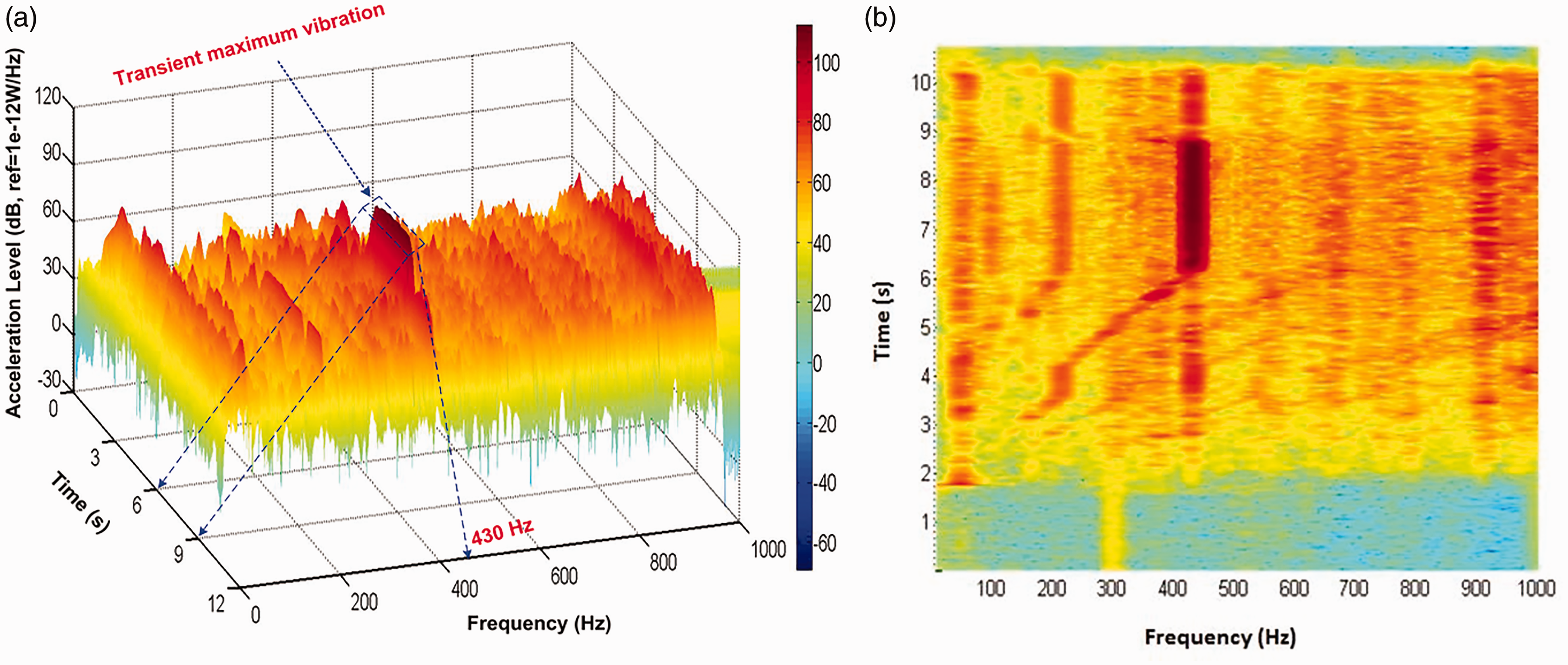
The STFT time–frequency spectrum. (a) Orthogonal view. (b) Top view.
Due to the non-stationary characteristics of the signal, the maximum amplitude spectrum whose energy (power density spectrum) is largest is used to evaluate the transient maximum excitation force by the STFT signal processing method. And the evaluation results are compared with the results derived from traditional FFT method as shown in Figure 7. It can be seen that the trends of the STFT results are almost the same with that of FFT results, which suggest the method used in this paper is correct.
The frequency response function matrix
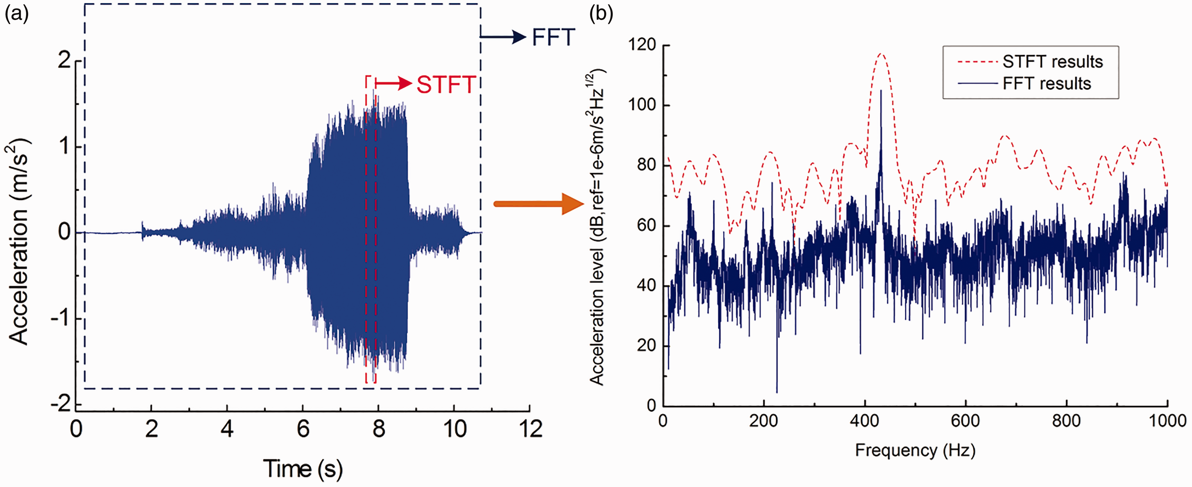
The amplitude spectrum of acceleration curves.
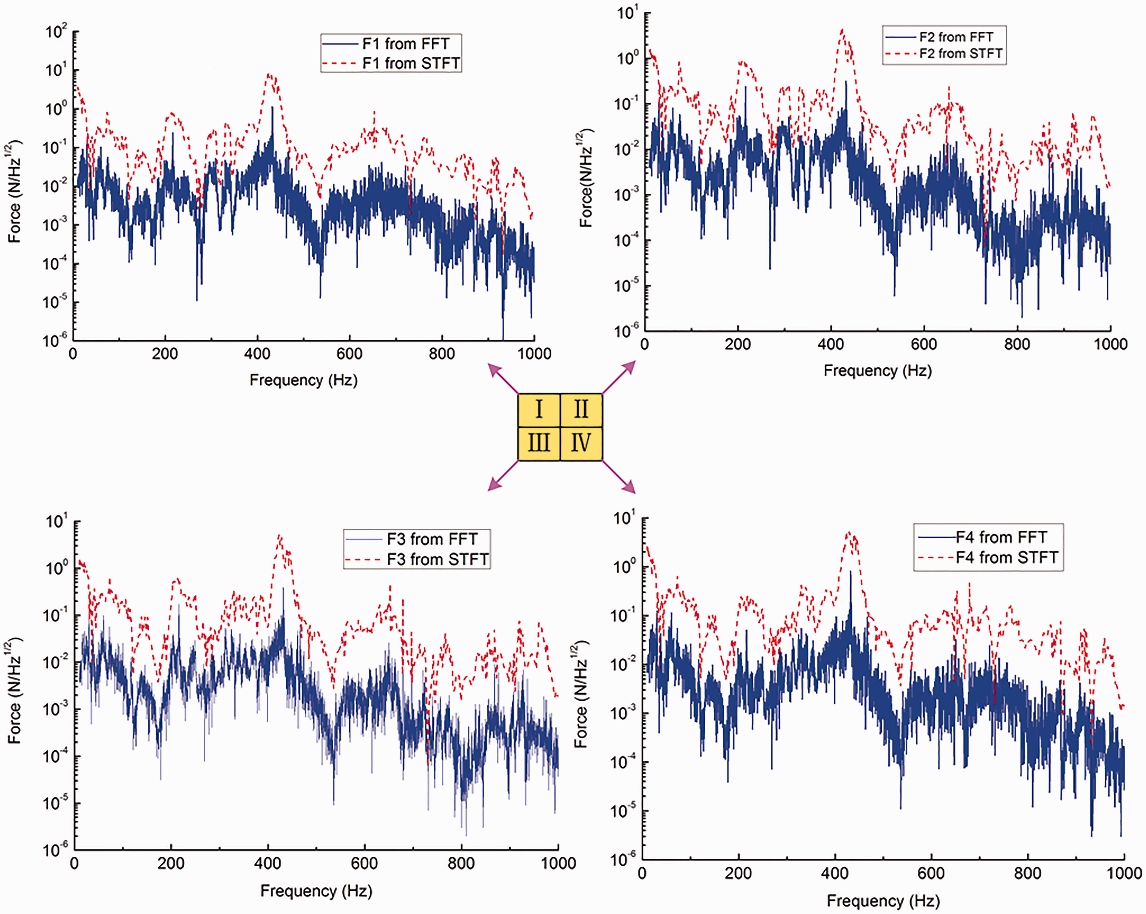
The force amplitude spectrum results of the foot positions.
The validation and error analysis of the excitation force results
Firstly, the response points 1–6 are selected to evaluate the excitation force
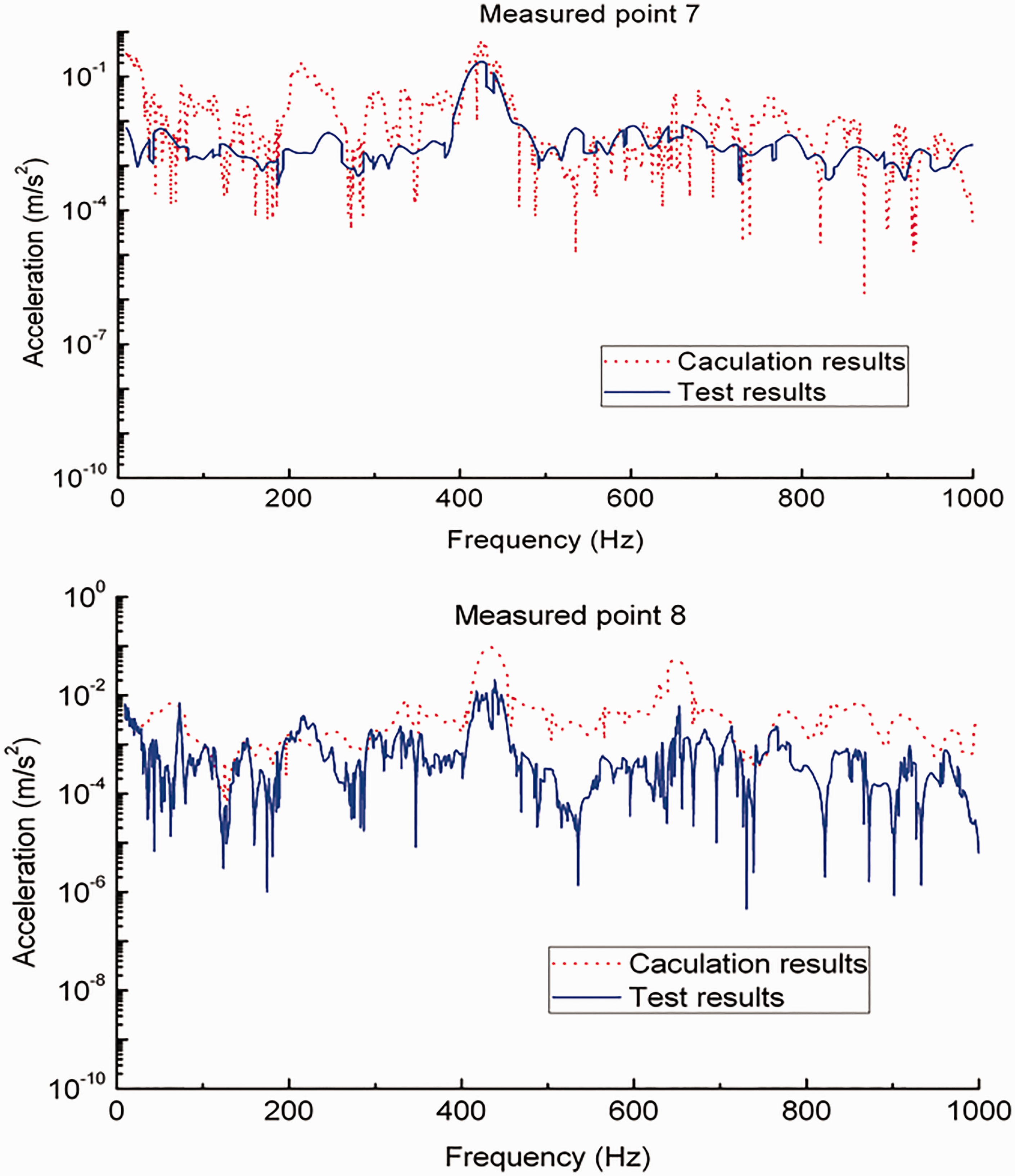
The verification of transient maximum excitation forces.
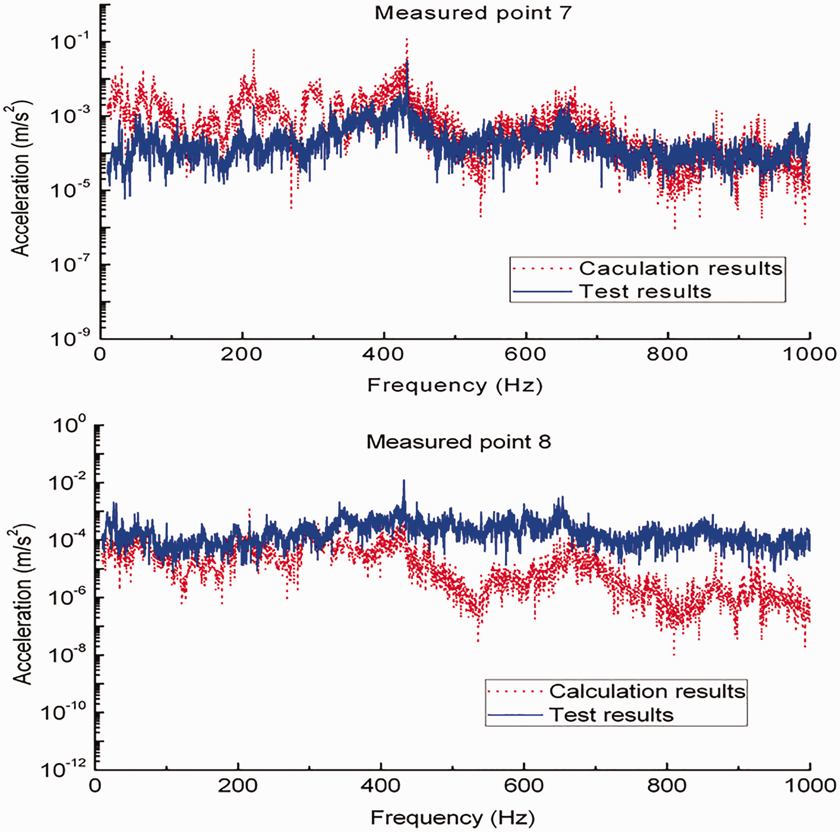
The verification of excitation forces from FFT.
It can be seen by comparing the calculation and test results of response point 7 that they are in a good agreement, which suggests that the excitation force results are accurate and feasible.
But there is still a certain amount of error between calculation and test results of response point 8 as well as point 7 in the low-frequency region of Figure 9, which could be resulted from the following probable reasons:
When the shafting was working, the extra excitation forces such as the friction forces between the shaft and bearing would influence the tested results; The error is generated by measuring instruments, including the acceleration sensor, force hammer, and so on; The numerical calculation error is generated by the truncated singular value method, data processing software, and so on. The signal to noise ratio is low due to the influence of the test environment; The influence of the longitudinal and lateral excitation force is ignored in this paper; The verification points 7 and 8 are far away from the excited points.
Acoustic radiation calculation of steering engine
The fluid–solid coupling vibration between the hull and the flow field will be caused by the excitation force, which can result into surrounding radiation noise. Because a cylindrical shell with ribs is the basic structure borne, which is usually used in underwater vehicles, taking excitation forces as an approximate input, a cylindrical shell whose two tips are simply supported is chosen as calculation model for the steering engine room of the underwater vehicle; the numerical solution of transient acoustic radiation for a cylindrical shell with ribs of the steering engine room is presented based on elastic shell theory and fluid–structure interaction theory.
Vibration and acoustic radiation of underwater cylindrical shell
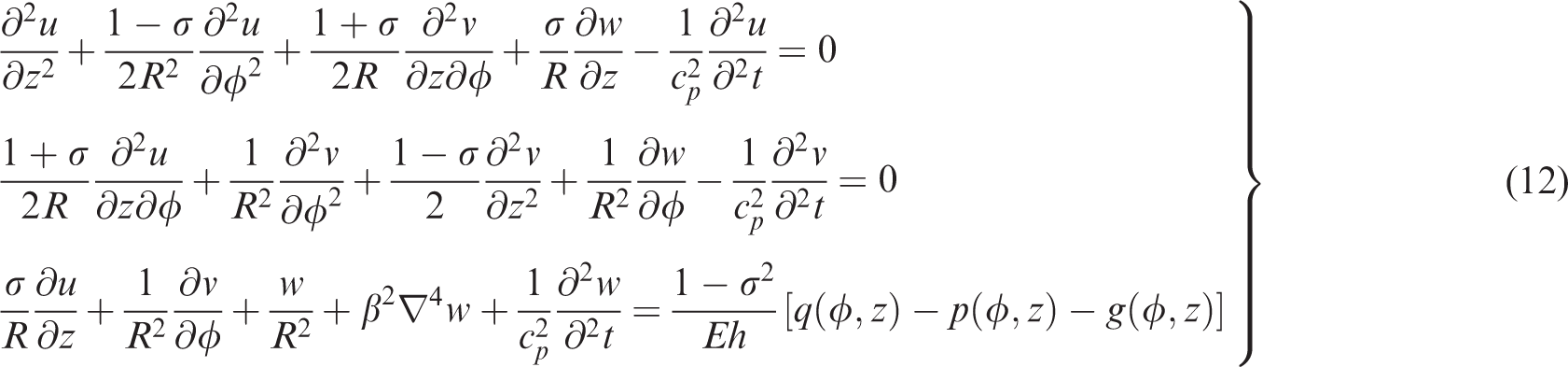
According to Burroughs,
20
equations of motion based on Donnell model of elastic cylindrical shell are given by
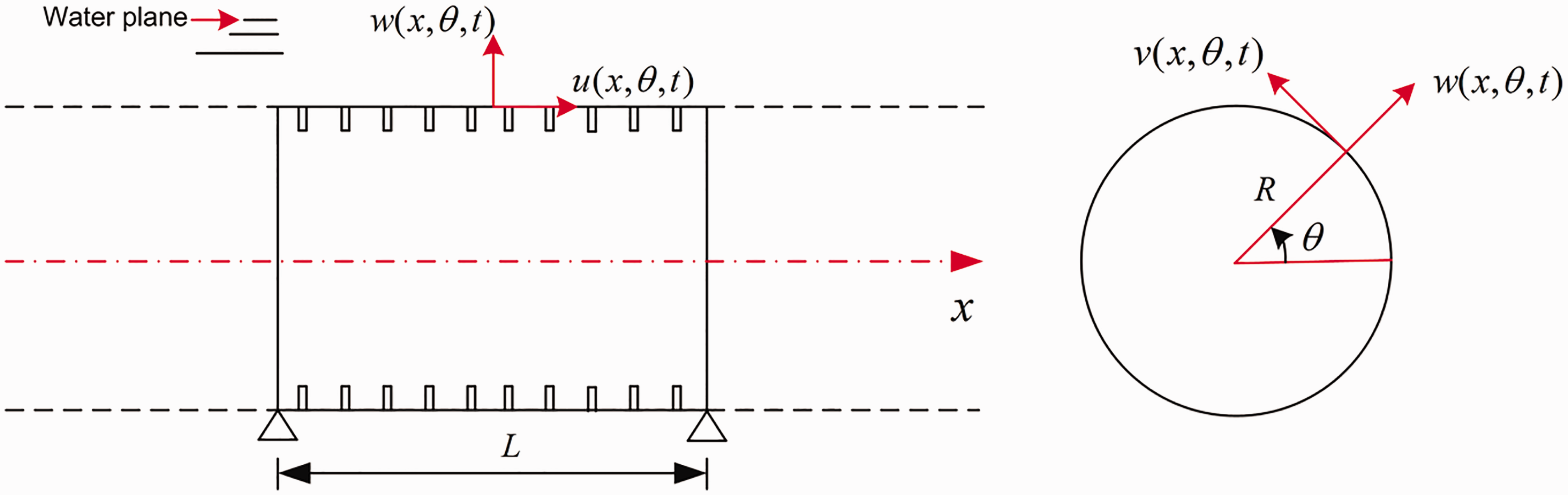
The coordinate of underwater cylindrical shell.
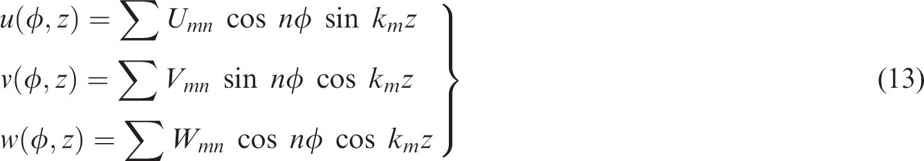
The modal superposition method is used, and the axial, circumferential and normal displacements are recognized as the following forms21,22

At the same time, sound pressure
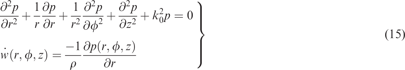
Finally, coupling vibration equation of circular cylindrical shell can be expressed as

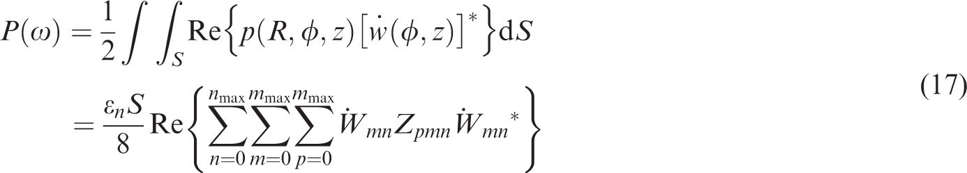
In this paper, the radiation noise resulting from steering engine can be equivalent to incoherent superposition of four single-point excitation, and by supposing that the excitation force act at the point
The radial vibration velocity amplitude
Numerical example
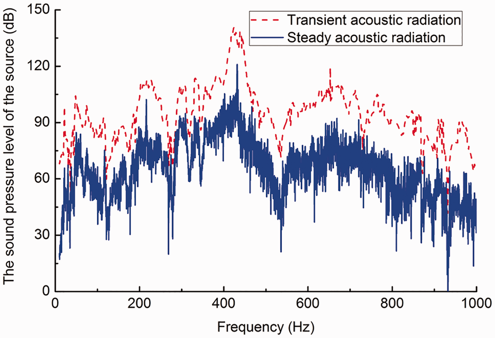
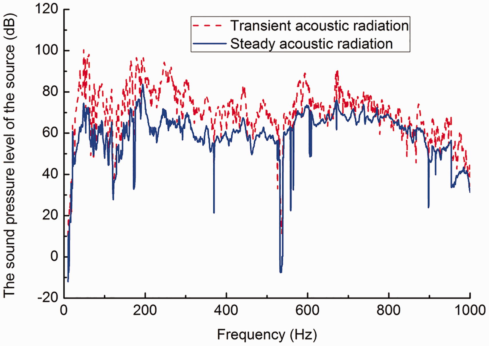
The steering engine room in the underwater vehicle is taken as an example, and the radius of cylindrical shell is R, length is 4.6R, thickness of the shell is 0.086R, the structural loss factor is 0.02; the sound pressure levels of the source on the two kinds of signals are shown in Figure 12.
Comparison of sound source level of electric steering engine 1.
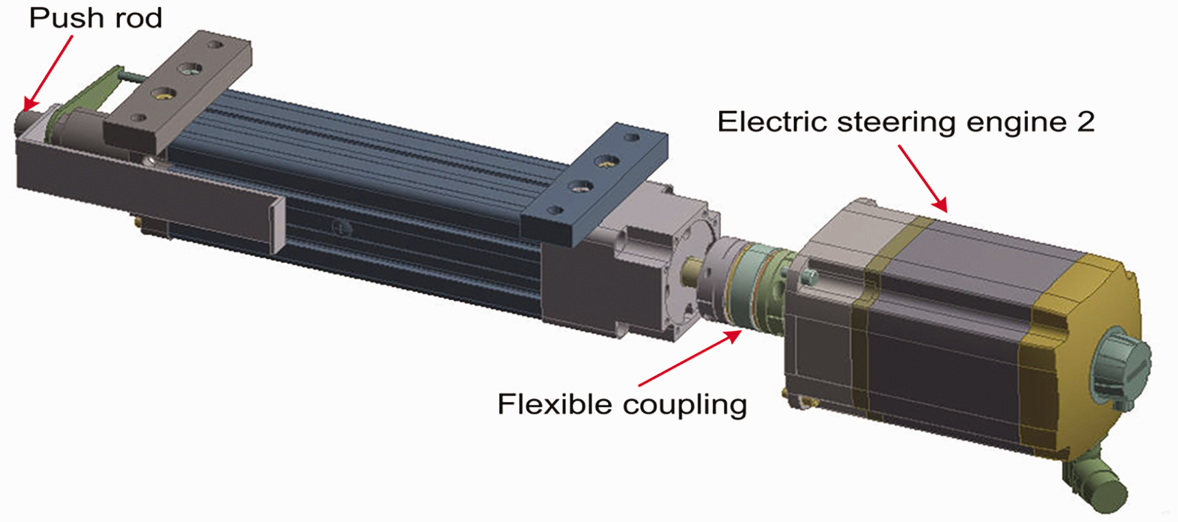
The electric steering engine 2 without retarder.
Comparison of sound source level of electric steering engine 2.
The transient results by the STFT method are higher than that by traditional FFT method, and the total sound pressure levels of the source are 151 dB and 121 dB, respectively. It has been shown that the non-stationary signal of the steering engine cannot be evaluated exactly as the traditional FFT method (usually used to evaluate the steady signal). The transient acoustic radiation of the electric steering engine 1 is higher than allowable value, and the possible reason is the gear retarder by which the high speed (1000 r/min) of the electric steering 1 is reduced to the design speed (120 r/min) of the shafting; therefore, another electric steering engine without retarder is chosen.
The source characteristics of electric steering engine 2 (Figure 13) are evaluated by the same method above, and the total sound source levels (Figure 14) are 124 dB and 96 dB, respectively, which meet design and use requirement.
Conclusions
The vibration tests for two types of electric steering engine are completed, on the basis of the tests, a method for evaluating the transient vibration and acoustic radiation is developed.
If characteristics of system have been known, the excitation force can be identified indirectly by the least square method in frequency domain, and the accuracy of the identification results is validated. The traditional FFT method for steady signal is not suitable for transient vibration and acoustic radiation caused by the steering engine when an underwater vehicle changes direction or depth. The whole and the local characteristics in the time domain and frequency domain can be studied by the STFT method, and a new method to evaluate transient vibration and acoustic radiation of steering engine is proposed in this paper. The transient vibration and acoustic radiation are higher when the gear retarder is running for the studied configuration in this paper.
Footnotes
Acknowledgments
The authors thank China Ship Scientific Center for giving a good surrounding, and the authors are grateful to the referees for their valuable suggestions.
Declaration of conflicting interests
The author(s) declared no potential conflicts of interest with respect to the research, authorship, and/or publication of this article.
Funding
The author(s) received no financial support for the research, authorship, and/or publication of this article.