
Abstract
An experimental model was made to investigate the influence of force and acoustic excitation on the vibration and underwater sound radiation of the stiffened conical-cylindrical shell. Meanwhile, a coupled precise transfer matrix method and wave superposition method was also proposed to analyze vibro-acoustic responses of combined shells. To test accuracy of the present method, vibration and acoustic results of combined shells are firstly examined. As expected, results of present method are in excellent agreement with the ones in literature and model test. The experimental results show that free vibrations of the experimental test are consistent with the literature data and the present method’s results. Forced vibration and acoustic test results are also well agreed with the numerical results from the coupled precise transfer matrix method/wave superposition method. The comparisons show that the coupled precise transfer matrix method/wave superposition method is reliable and credible to solve the vibro-acoustic response of combined shells. The analysis shows that the acoustic excitation is the key factor for radiated noise in low-frequency range. However, the radiated noise resulted from force excitation is dominant in mid-high frequency band.
Introduction
Widely used in aeronautical and naval industries, the ring-stiffened conical-cylindrical shell is one of the most normal structure of mechanical engineering, the radiated noise of which is a classic acoustic-structure interaction problem.1,2 There is a lot of literature research on vibration and sound radiation of various shells (spherical shell, 3 cylindrical shell 4 and conical shell 5 ) and some attentions on the structure dynamic analysis of conical-cylindrical shells have been made public.6–17
Regarding the numerical analysis of sound radiation of submerged elastic structure, several numerical methods such as finite element method (FEM), boundary element method (BEM) and coupled FEM/BEM are available to predict and analyze the acoustic problem. The traditional way of FEM18 is to transform an infinite domain problem into a finite field problem by defining artificial boundary conditions, while because of its requirement for the Green function, BEM19 is well suited for the infinite domain problem; The vibration and sound radiation of submerged elastic structures can be predicted directly by coupled FEM and BEM. 20 Liu and Chen 21 used a coupled FEM/BEM to analyze the vibration response of submerged cylindrical shells in conjunction with the wave number theory. The effect of mass distribution and isolation in a submerged hull was investigated by developing a fully coupled finite element/boundary element (FE/BE) model. 22 The fluid–structure interaction problem can be solved by constructing the low-order shape functions and generating the discrete element meshes. Due to these fundamental assumptions, the development of FEM and BEM is now limited in many prospects. As the frequency increases, the number of required elements and memory space will surge sharply, and computational efficiency reduces seriously in contrast.
The vibro-acoustic response of a few simple structures such as spherical shells, 3 cylindrical shells 4 can be calculated directly by the analytic method. Due to the cone vertex of conical shell, 5 tension-bending coupling term in the constitutive equation increases the mathematical complexity and calculation difficulty. There are many researchers paying attention to the vibration and sound radiation of the cylindrical shell, but paying attention to acoustic characteristics of combined shells is less. Caresta and Kessissoglou 23 analyzed a submarine’s acoustic responses under harmonic force excitation. In order to improve the computational efficiency and frequencies, Wang et al. 24 developed a precise transfer matrix method (PTMM) and solved a set of first-order differential equations to obtain vibro-acoustic responses of submerged stiffened combined shell and conical shells. Qu et al. 25 predicted the vibration and acoustic behaviors of circumferential and longitudinal rings stiffened submerged spherical–cylindrical–spherical shells. An improved variational method combined with a way of multi-segment partitioning was present to formulate the coupled stiffened shell model, whereas a Kirchhoff–Helmholtz integral formulation is used to simulate the exterior fluid.
The present work aims to analysis the noise and vibration results of experiment model, which was constructed to simulate a submerged stiffened conical-cylindrical shell under the acoustic and force excitation. To the authors’ knowledge, there are few references concerning vibro-acoustic behavior of combined shells in force and acoustic excitation case. The authors tested the experiment model to obtain the combined shell’s free vibration, forced vibration and acoustic response in air and water. The structural and acoustic responses were also determined by a coupled PTMM/WSM, which is suitable for assessing distributive systems’ vibro-acoustic responses. Two models of combined shells from Chen et al., 11 Qu et al. 12 and Caresta and Kessissoglou 23 were employed to compare with the results from the coupled PTMM/WSM method to verify its effectiveness, which is also proved by comparison between the present method and experiments results. Meanwhile, the vibration and sound radiation characteristics of the stiffened combined shell are investigated under different types of excitation.
Experimental research
As shown in Figure 1(a), the experimental model is a single ring-stiffened conical-cylindrical shell. And welding was not considered to accord with the theoretical model. The material properties of the conical-cylindrical shell are as follows: Length
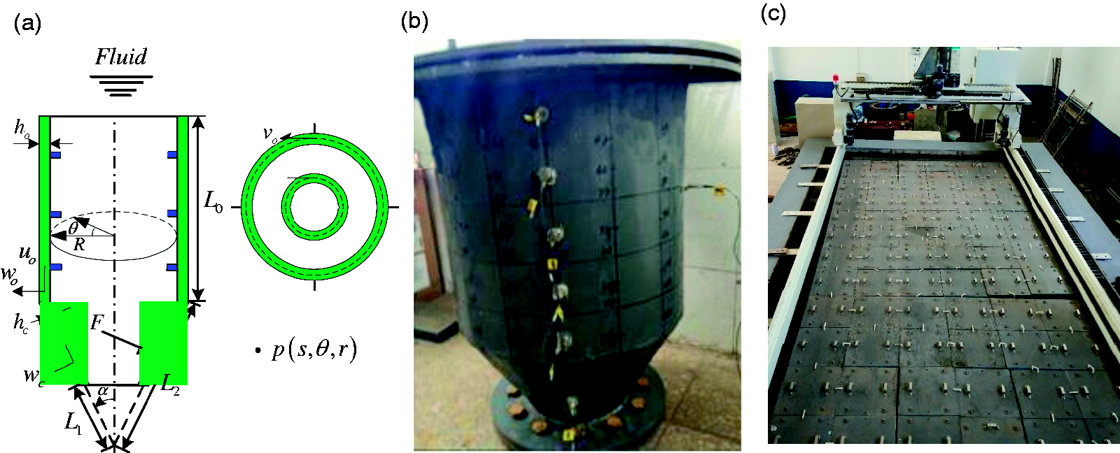
Pictures of an axisymmetric stiffened conical-cylindrical shell: (a) the schematic diagram; (b) test model; (c) anechoic tank with a running gear.
The vibration measurement system is composed of anechoic tank, hammer, vibration exciter, signal generator, power amplifier, data acquisition device, acceleration sensor, force sensor, and hydrophone. The anechoic tank is 8 m in length, 4 m in width and 3 m in depth. The wedge-shaped sound absorption cone is installed on the inner surfaces of the water pool. The anechoic tank and test model are shown in Figures 1(c) and 2(a).
A patch (10 mm in diameter) screwed to a shaker is glued on the inner surface of the combined shell. The exciter is fixed on the both end caps to excite the point with cylindrical coordinates (x, r, θ) = (0.25 m, 0.25 m, 0) in which x = 0 is at the bottom of the cylindrical shell segment. The force excitation type is sinusoidal, the amplitude of which is 1 N. There are two components between the shaker and the patch: one is an impedance head (PCB-208C02) for the measurement of acceleration and force, another is a threaded rod which allows a punctiform radial excitation acting on the shell. There is a flexible rope to connect the hoisting machine and the model. A hydrostatically balanced loading is employed to be located on the shell’s top cover. Taking advantage of the axial symmetries of the combined shell, a series of measuring points along the circumferential and axial direction can be arranged to obtain the vibration acceleration. Ten acceleration sensors (PCB-352C03) are set to measure the radial vibration acceleration of the outer surface for several cases. The positions of these sensors as shown in Figure 2(b) are located at Position 1 (0.09 m, 0.25 m, 0), Position 2 (0.17 m, 0.25 m, 0), Position 3 (0.25 m, 0.25 m, 0), Position 4 (0.33 m, 0.25 m, 0), Position 5 (0.41 m, 0.25 m, 0), Position 6 (0.625 m, 0.1778 m, 0), Position 7 (0.25 m, 0.25 m, π/2), Position 8 (0.25 m, 0.25 m, π), Position 9 (0.625 m, 0.1778 m, π/2) and Position 10 (0.625 m, 0.1778 m, π).
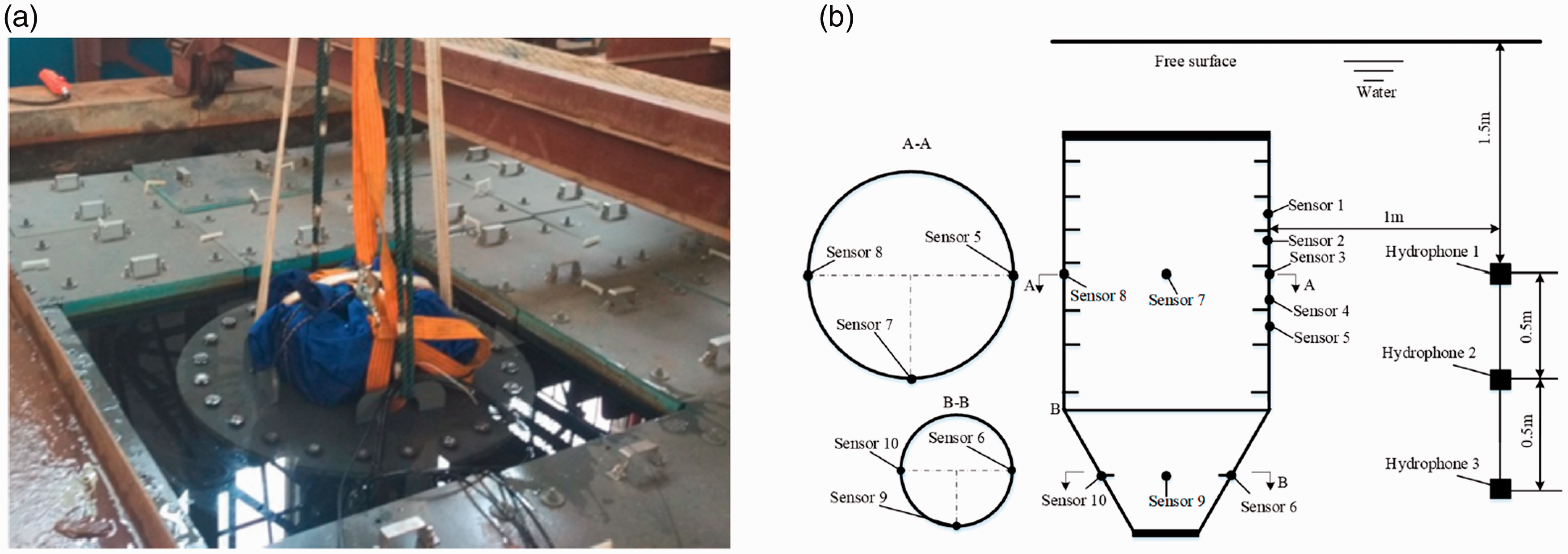
Experimental setup for the stiffened conical-cylindrical shell submerged in water: (a) The measurement excitation system; (b) The layout of measuring points.
Vibration solution for combined shells
Based on Flùgge shell theory, the equations of revolutionary shell can be written in the matrix differential equations

The conical-cylindrical shell can be separated into several parts, and the node coordinates are

The effect of stiffeners on the shell is reflected on the variation of the state vector. Internal forces (moment, shear and axial force) are changed between the left section

The relation between the displacement

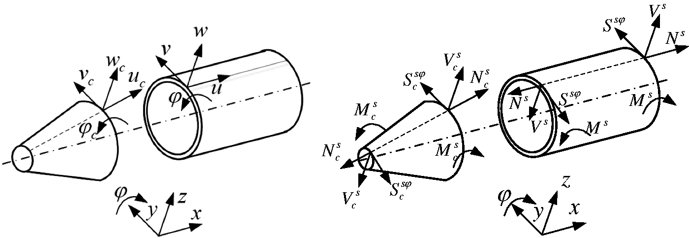
Sign convention for the forces, moments and displacements of the cone and cylinder.
Likewise, the relation between internal forces of conical shell component

Based on the internal forces and displacements connection conditions, the state vectors at the junction satisfy

Numerical solution of acoustic response
Geometrically similar to the real boundary S, a virtual boundary

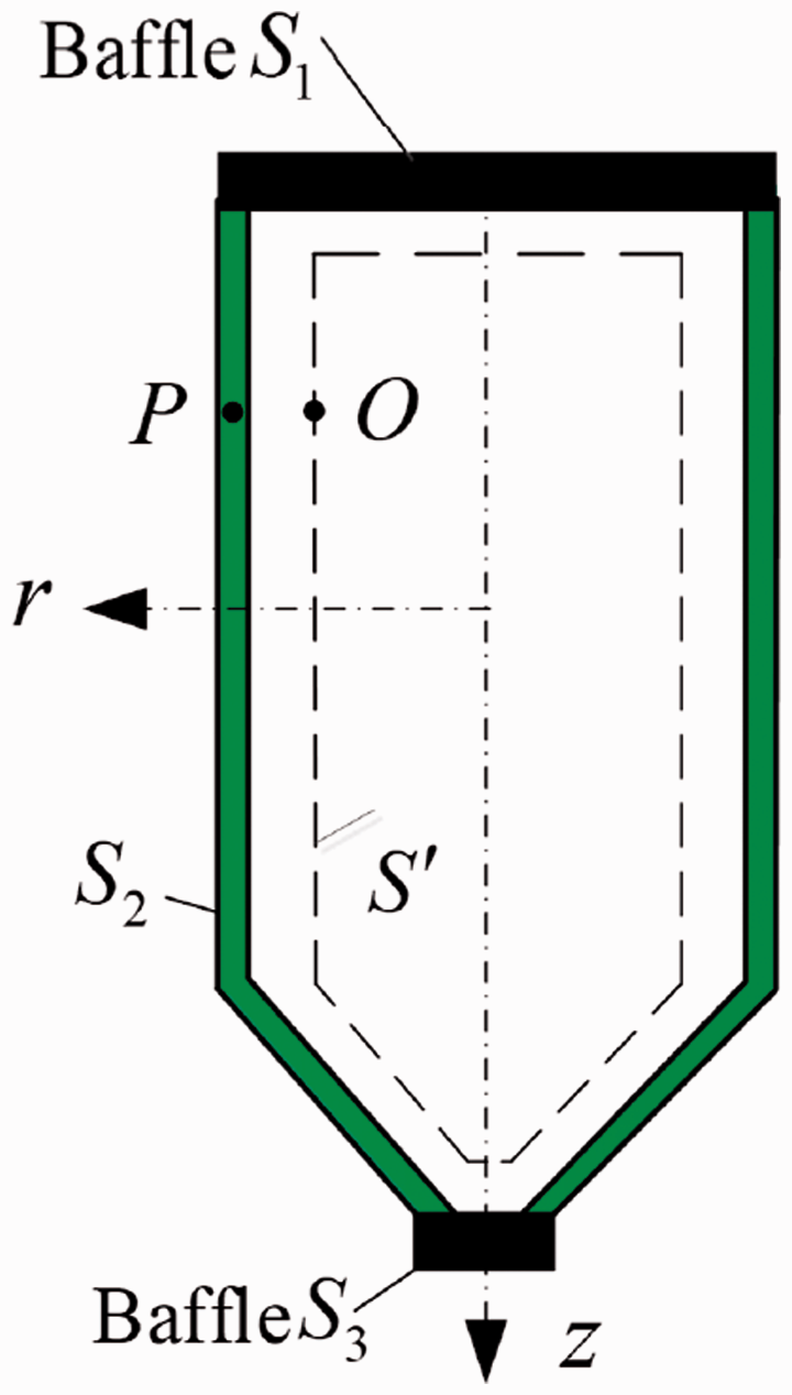
Surface boundary and virtual boundary of the conical-cylindrical shell.
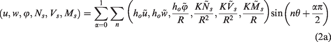
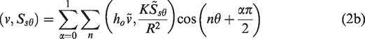
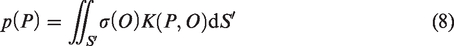
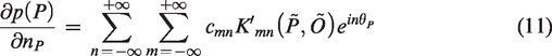
The source strength function
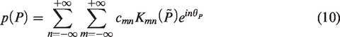
The normal derivative of the sound pressure can also use a complex Fourier series to expand as
Points

The ith rib state vector

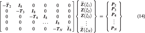
The governing equations of the combined shell can be integrated by gathering equation (13). Based on the boundary conditions, by finding the line numbers of determinate state vectors in
The state vectors
According to the linear superposition method, the radial displacement on the surface S can be described as
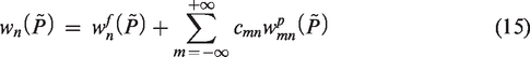
After replacing equation (12) by equation (15) and selecting q (q > 2m + 1) collocation points on the meridian of the surface S, several linear algebraic equations can be described as

Results and discussion
Free vibration results and discussions
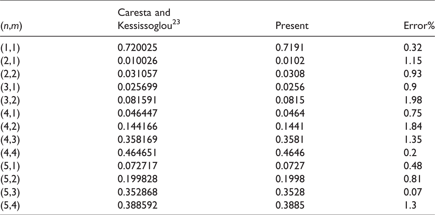
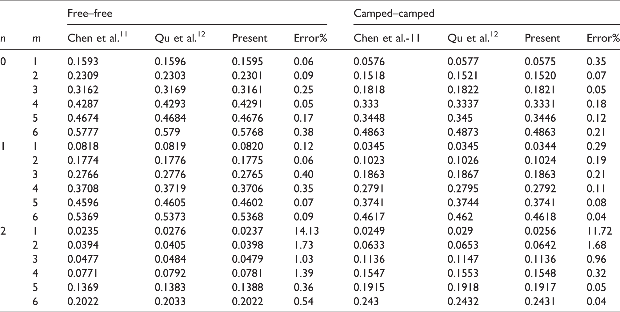
To verify the accuracy of the coupled PTMM/WSM method, a conical-cylindrical shell in Caresta and Kessissoglou23 with free–free boundary conditions was employed, of which the parameters are as follows:
Comparison of frequency parameters of the model in Caresta and Kessissoglou. 23
Another conical-cylindrical shell model in Chen et al.
11
was also borrowed to assess the precision and accuracy of this method. The parameters of the combined shell are as followed:
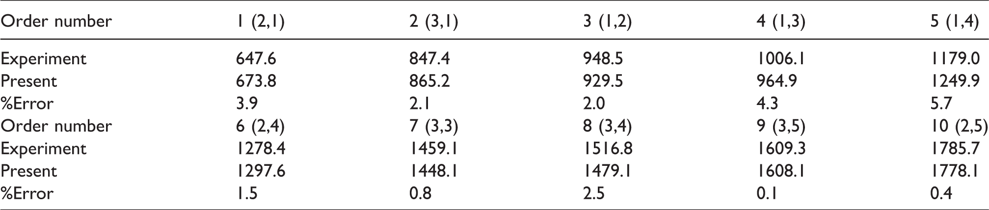
Stuck to the measuring points (position 1 to position 10), acceleration sensors relate to the data acquisition system. And a force hammer is used to thump structure model. The free vibration of the experiment model hoisted by a flexible rope is carried out by an impact hammer (PCB 086C03) and several accelerometers (PCB 353B15) to obtain the natural frequencies and structural modes by the vibration response analysis processing module (HBM Quantumx1615B). To verify the accuracy of vibration responses, the natural frequencies values calculated by the present method are compared with the experimental results. The first 10 orders of the natural frequencies values are given in Table 3, which include the numerical results and experimental results.
Comparison of natural frequencies of the conical-cylindrical shell in air case.
Forced vibration results and discussion
The forced vibration tests under the exciter and the non-directional dodecahedron sound source excitation are, respectively, carried out in air and water condition. During this process, a sinusoidal single frequency signal is generated as the input signal. To amplify the signal, the power amplifier is driven with the linear sweep frequency (100 Hz–2500 Hz). The data measured by acceleration sensors are transformed into vibration acceleration level by formula
In the air condition, the 10 measured points’ acceleration data were disposed to obtain the acceleration level in the frequency band. The coupled PTMM/WSM is also employed to calculate the vibration response of the experimental model. The boundary conditions of the both ends are supposed to be clamped. The vibration response under the force excitation is shown in Figure 5. Apparently, the variation tendency of the both frequency response curves is consistent. In the 100–500 Hz band, the vibration response curves predicted by the coupled PTMM/WSM coincided very well with experimental curves, except some loss of resonance peaks. It is because that the peak frequency 141 Hz and 224 Hz is corresponding to the nature frequencies of the end cap. Although the both vibration response curves have a little difference at the resonance peak in the range of 500–2000 Hz, the results from the present method are still consistent with experimental values in the air case. In the frequency up to 2500 Hz, the resonance peak numbers of test model are more than that of the coupled PTMM/WSM, and acute fluctuation also appears in phase advance and peak position. In authors’ view, the difference between two curves is partly because of the local vibration of the end caps and seal flanges. Also, the conditions of actual boundary cannot be perfectly like the clamped boundary. But in general, the results show that the present method is reliable, from which the results are also credible.
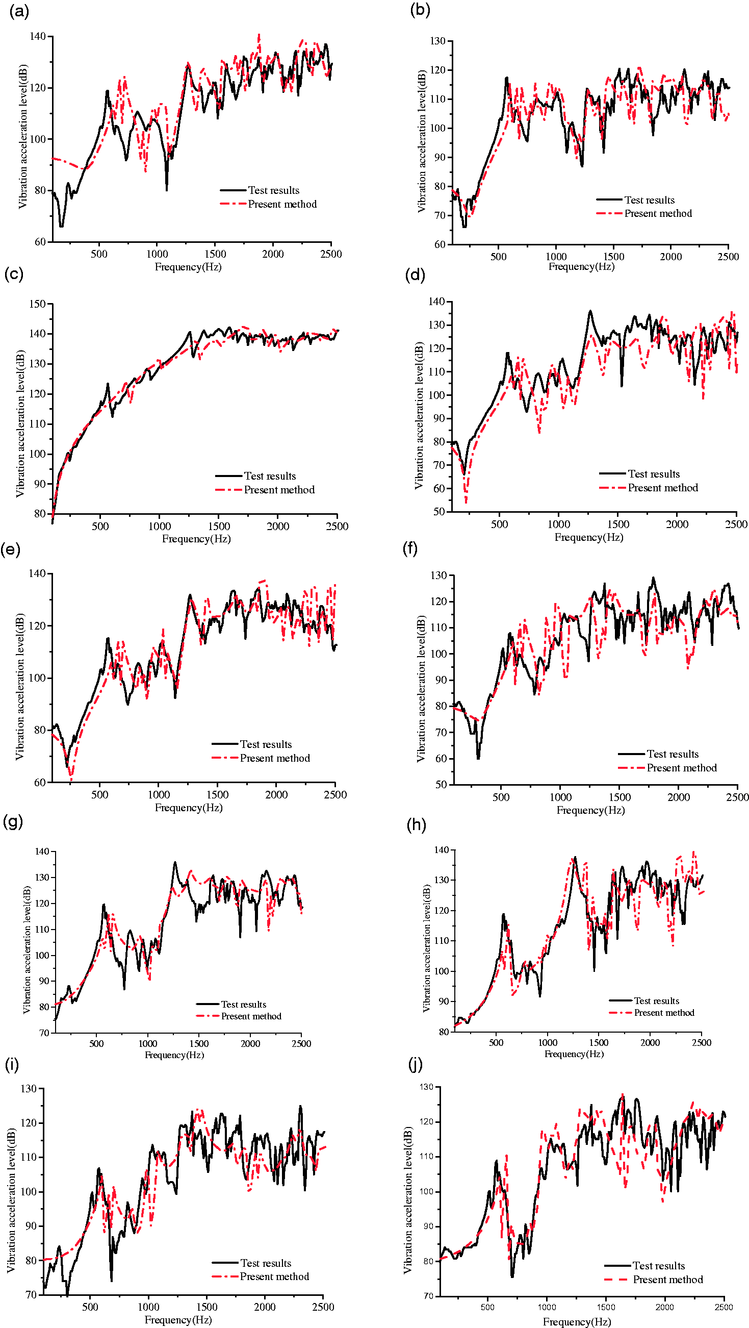
The forced vibration response of the conical-cylindrical shell in the air: (a) position 1, (b) position 2, (c) position 3, (d) position 4, (e) position 5, (f) position 6, (g) position 7, (h) position 8, (i) position 9 and (j) position 10.
As shown in Figure 6, the forced vibration responses of the submerged conical-cylindrical shell were also carried out in frequency of 100–2500 Hz. In both air case and water case, the first 10 natural frequencies (see Table 3) are in good agreement with the peak frequencies of forced responses curves (see Figures 5 and 6). Although there is some obvious difference between the two curves in the 100–600 Hz band, the vibration variation trend predicted by the coupled PTMM/WSM is basically consistent with experimental values. The existence of water leads to a strong structure-acoustic coupling interaction. The experimental results have some resonance peaks resulting from global vibration modes of entire test model and local vibration modes of end cap and the sealing flange. However, the numerical model does not contain these vibration modes. In the 600–1500 Hz band, the results from the coupled PTMM/WSM are consistent with the experimental results. The experiment results and the numerical results still are a little different at the peak frequencies. In the 1500–2500 Hz range, the peak numbers of experiment model are more than that of numerical model. There is an obvious difference between both the frequency response curves, partly because of the local vibration of the end cap and model. As a group, the results from the present method are consistent with the vibration trend of the experimental results.
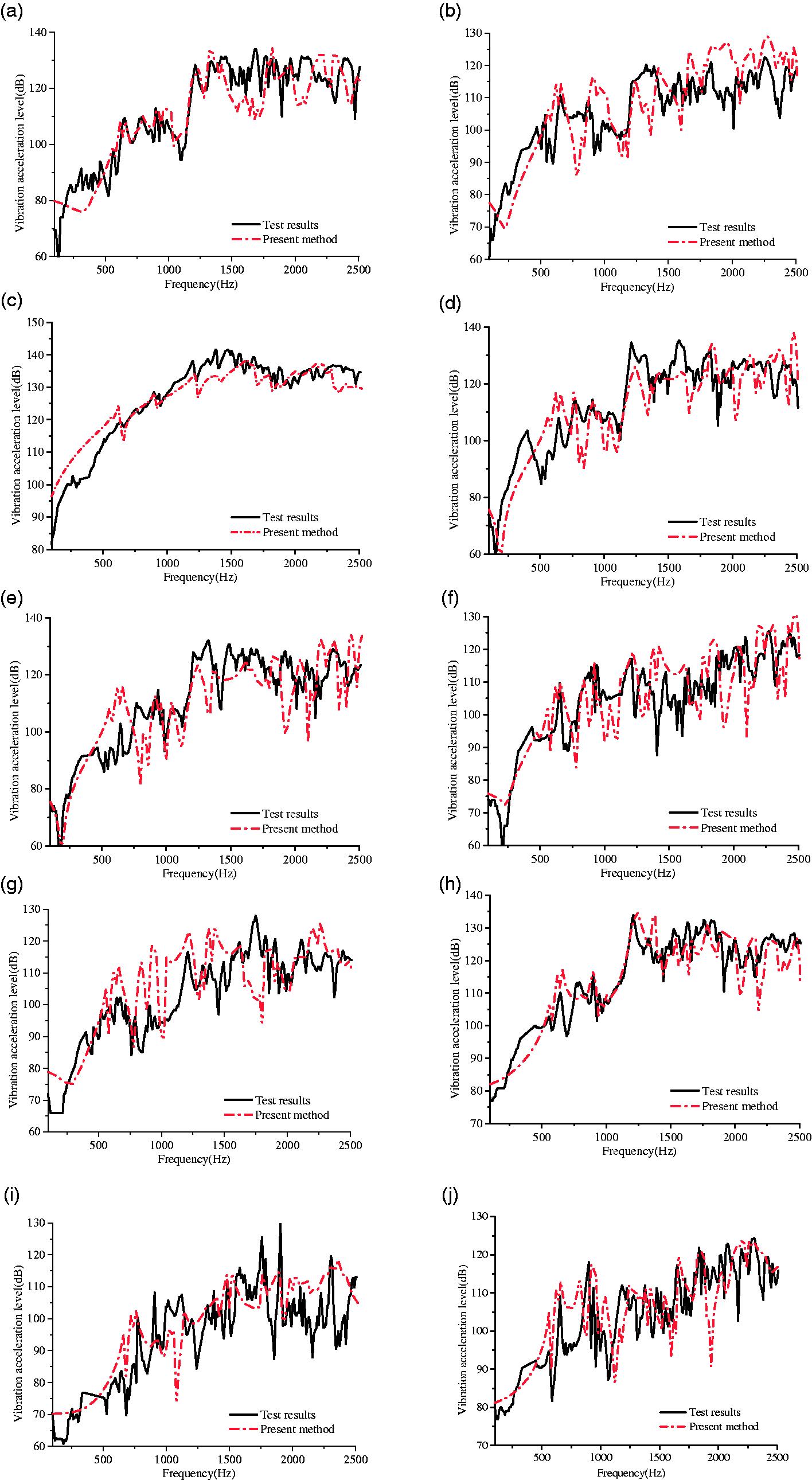
The forced vibration response of the conical-cylindrical shell in the water: (a) position 1, (b) position 2, (c) position 3, (d) position 4, (e) position 5, (f) position 6, (g) position 7, (h) position 8, (i) position 9 and (j) position 10.
Radiated noise results and discussion
As shown in Figure 2, before submerging into the anechoic tank, the conical-cylindrical shell model and the two end caps are sealed with water sealant. The signal generator generated the input signal, and drove the shaker and the non-directional dodecahedron sound source to work. The surrounding fluid is water with the density of 1000 kg/m3 and the sound velocity of 1500 m/s.
27
Then the noise from the vibrating surfaces of the conical-cylindrical shell was radiated into the water. As seen in Figure 2(b), there are three hydrophones (BK-8104) arranged 1.0 m far from the surface outside the shell to measure the sound pressure in the anechoic tank. In the case of force and acoustic excitation with the linear sweep frequency (100 Hz–2500Hz), the data are transformed into a sound pressure level
Comparison between the experimental results and numerical results of measuring points (hydrophone 1, hydrophone 2 and hydrophone 3) under the force excitation is shown in Figure 7. Although both the vibration response curves have a little difference at the resonance peak in the range of 500–2500 Hz, the sound pressure results from coupled PTMM/WSM are consistent with experiment results. When air is full in the internal medium of the test model, the coupling of acoustic cavity mode and structural mode has little effect on the vibro-acoustic response of the conical-cylindrical shell. The sound radiation computed by the coupled PTMM/WSM is related to the structural vibration mode with force excitation. It suggests that the coupling of acoustic cavity mode and structural vibration mode can be neglected. The results from the coupled PTMM/WSM miss some resonance peaks compared with the experiment results in the frequency of 1000–1500 Hz. As the investigation is performed, the analysis result of research model is totally corresponding with the previous conclusion.
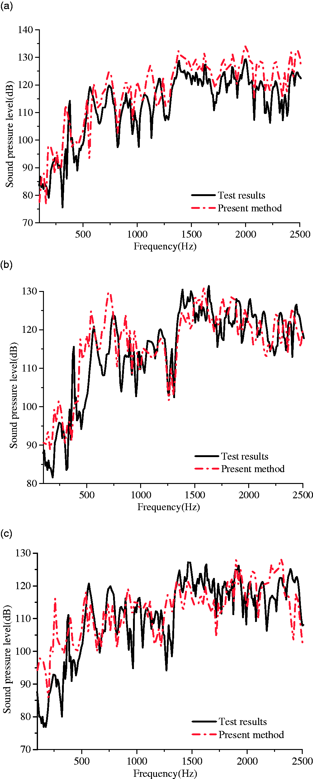
Comparison of sound pressure level of the measurement point with force excitation: (a) hydrophone 1, (b) hydrophone 2, (c) hydrophone 3.
Comparison of the experimental results and numerical results on measured points under the acoustic excitation is shown in Figure 8. The comparison in the force and acoustic excitation case is also shown in Figure 9. Although the overall trend of numerical results from the coupled PTMM/WSM is consistent with that of experimental results, there is some difference of peak frequencies in low-frequency band. That’s because the experimental model has a reverberant field and structure-acoustic coupling. The structure-acoustic coupling between interior acoustic cavity modes and structural vibration modes has some effect on the sound radiation of the combined shell in low-frequency band.
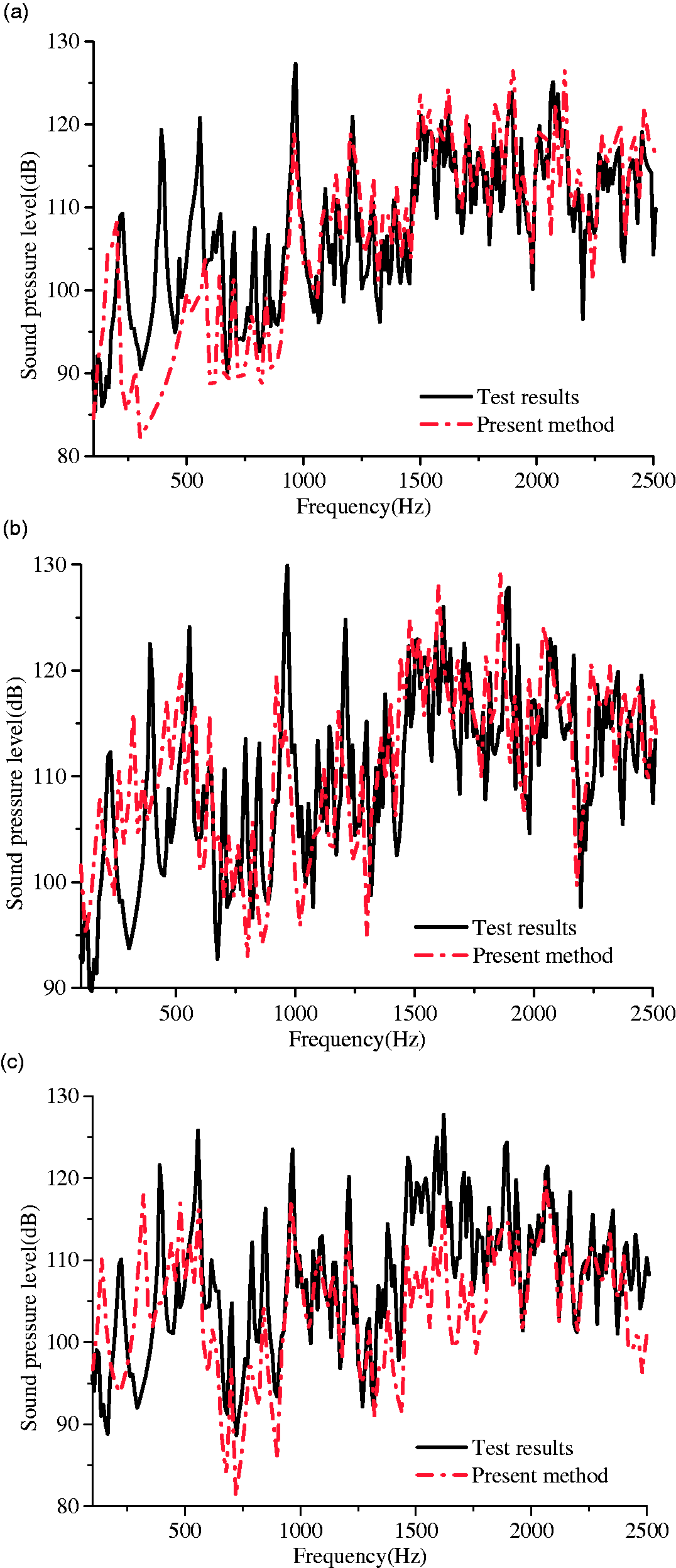
Comparison of sound pressure level of the measurement point with acoustic excitations: (a) hydrophone 1, (b) hydrophone 2, (c) hydrophone 3.
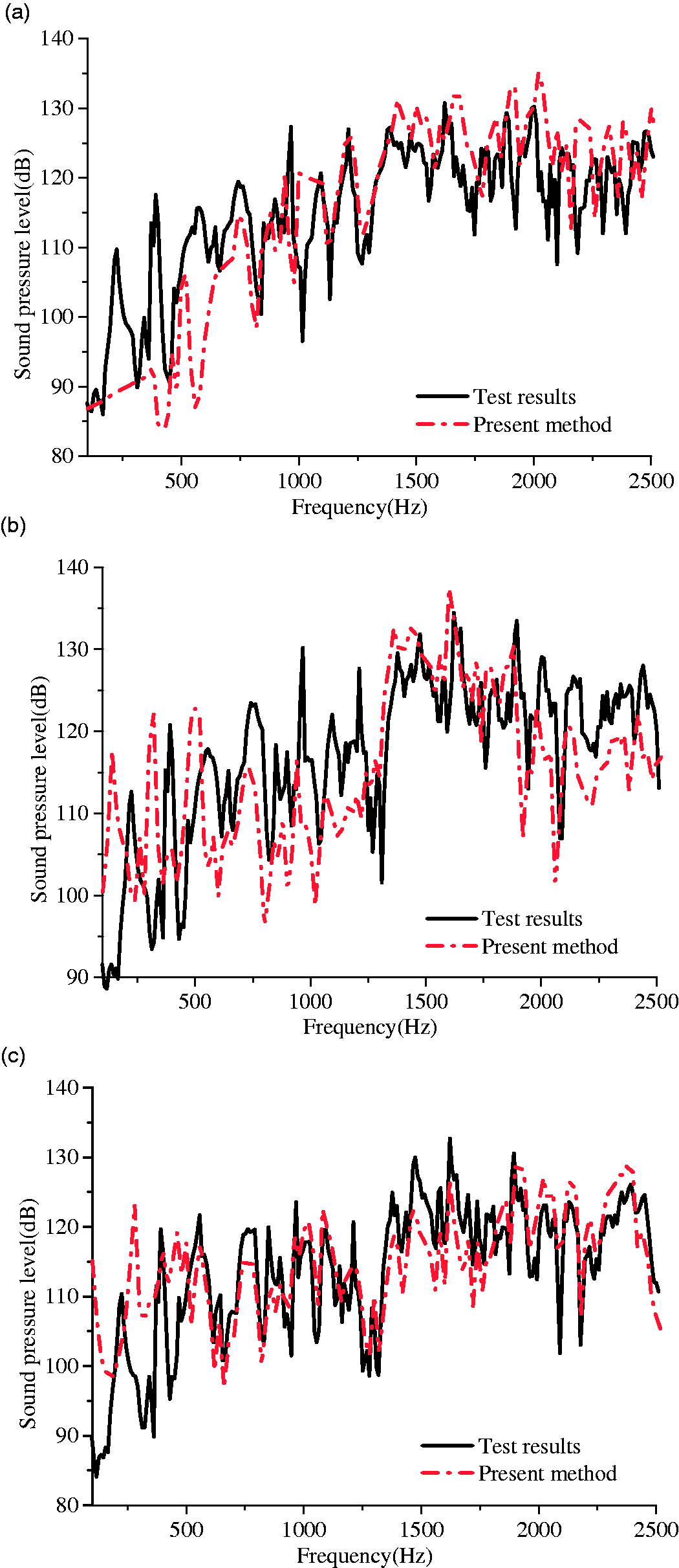
Comparison of sound pressure level of the measurement point with force and acoustic excitations: (a) hydrophone 1, (b) hydrophone 2, (c) hydrophone 3.
As shown in Figure 10, sound pressure values of all measured points are compared under different cases of excitations. There is obvious difference in peak numbers and frequencies between acoustic excitation case and force excitation case. The main difference in both cases is that some peak values only exist in the low-frequency range of force excitation case, while some peak values only exist in the middle frequency range of acoustic excitation case. This suggests that the sound pressure’s peak value in the force excitation case is related to the structural natural frequencies. The peak values of sound pressure in acoustic excitation case are related to the natural frequencies of the shell and internal cavity. On the whole, it is shown that the acoustic excitation is the key factor for radiated noise in low-frequency band. However, the radiated noise resulted from force excitation is dominant in mid-high frequency band. The variation tendency of sound pressure level under force excitation is in agreement with the results under force and acoustic excitation. In 300–1300 Hz frequency range, in spite of little difference in peak values, sound pressure levels are of the same order under force and acoustic excitation.
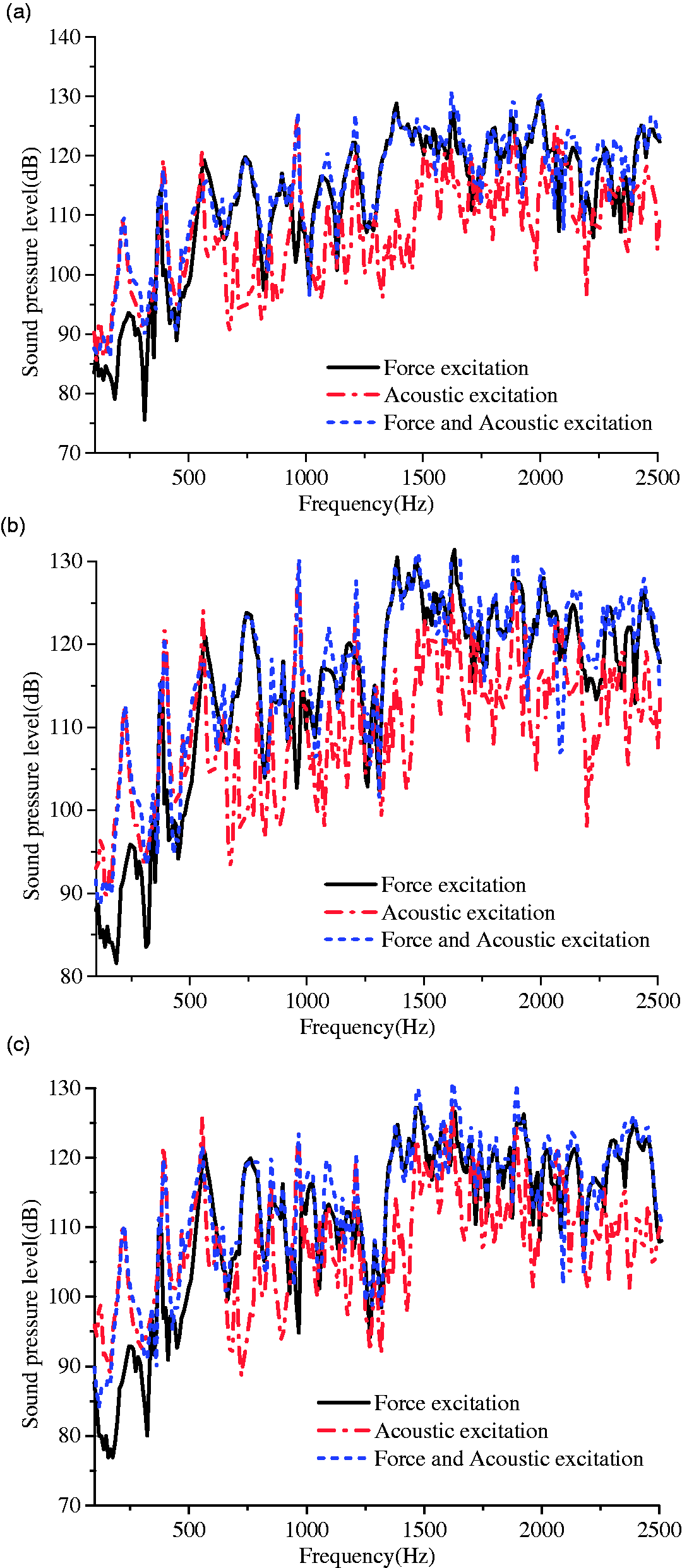
Comparison of sound pressure level of the measurement point with different excitations: (a) hydrophone 1, (b) hydrophone 2, (c) hydrophone 3.
Conclusion
In this paper, the experimental test of a ring-stiffened conical-cylindrical shell on the vibration and sound radiation is investigated under different types of excitations. The test of vibration and acoustic responses under different excitations is carried out and the experimental data are analyzed. The coupled PTMM/WSM is used to solve the vibration acoustic response of conical-cylindrical shell in air case and water case and then compared with the experimental results. It can be concluded as follows:
Comparing the numerical results including the vibration and acoustic responses with the literature data and experimental results, it is shown that coupled PTMM/WSM is feasible to solve the vibration and acoustic problem of the submerged combined shell under cases of excitations. The forced vibration of the submerged conical-cylindrical shell in the water case has little difference compared to the air case in the low-frequency range. The vibration values of the conical section of the combined shell in water case are significantly less than that of air case. Fluid load is the primary factor that can affect the circumferential mode and local mode of conical section. The peak values of sound pressure in force excitation case are relate to the natural frequency of the shell. The peak values of sound pressure in the acoustic excitation case are relate to the natural frequency of the shell and interior cavity. The acoustic excitation is the key factor for radiated noise in low-frequency band. However, the radiated noise resulted from force excitation is dominant in mid-high frequency band.
Footnotes
Declaration of conflicting interests
The author(s) declared no potential conflicts of interest with respect to the research, authorship, and/or publication of this article.
Funding
The author(s) disclosed receipt of the following financial support for the research, authorship, and/or publication of this article: This research was supported by the National Natural Science Foundation of China (No. 51779201), China Scholarship Council (201806955052) and Nature Science Foundation of Hubei Province (2018CFB607).