
Abstract
Ground vibrations induced by man-made sources like vibrating machinery, vehicular movement, traffic, construction activities involving pile driving, blasting, dynamic compaction, etc., are rising rapidly and may disrupt nearby sensitive equipment, distress, and damage sub-structures. Therefore, vibration isolation is necessary to mitigate ground-borne vibrations with suitable techniques in the present-day context. Trench barriers are one of the most efficient techniques when the other isolation techniques are inefficient at the source. Although the open trench barriers are the most efficient, their stability is still a significant concern. Hence, these trenches are generally filled with suitable absorbing materials such as sawdust, geofoam, and concrete. The present study has attempted to explore the feasibility of using shredded tire chips as an infill material by evaluating their performance using the finite element method. The performance of tire chips–filled trench barriers predicted using FE analysis is also compared with the performance of other common infill materials such as sawdust and geofoam. Numerical studies show that the vibration isolation efficiency and their performance are highly sensitive to the shear wave velocity of the soil and infill material density for infill trenches. The key findings of the study suggest that shredded tire chips can also be used as an infill material in trenches for reducing ground-borne vibrations, and its performance is comparable with geofoam-filled trenches.
Keywords
Introduction
Ground vibration has become a significant concern with rapid urbanization and associated activities. Traffic, vibrating equipment, pile driving, machine foundation, blasting, etc. induce ground vibrations, eventually affecting nearby structures. The intensity of vibration depends on the amplitude and frequency of the vibrating source and the properties of the propagating medium. Ground vibration propagates through the soil medium as body waves (compression and shear waves) and surface waves (Rayleigh and Love waves). For vibrating sources at/close to the ground surface, a significant part of vibration energy is carried in Rayleigh waves, 1 about two-thirds of the total energy. Rayleigh waves travel near the surface of the soil medium, and their attenuation with distance is much slower than the body waves. These vibrations propagate through the soil medium to adjacent structures and may cause damage to the structures and discomfort to the people residing there. These vibrations are unwanted near the structures housing sensitive or high-precision instruments since they can cause them to malfunction. Thus, these are the primary concerns in vibration isolation problems because they carry a significant portion of the energy being transmitted and much slower attenuation with distances. The vibrations caused by these waves can effectively travel longer distances and may be annoying to people and structures. Therefore, it is essential to mitigate these vibrations as and when needed.
Mitigation of ground-borne vibrations using wave barriers is one of the commonly used techniques in vibration isolation and is generally constructed across the line of propagation of surface waves. These wave barriers scatter the ground-borne vibrations, and their performance depends on the location, geometry, and composition of the materials used. These wave barriers can be in the form of trenches (open or infilled), sheet pile walls, or rows of solid or hollow concrete or steel piles. The difference in the material impedances in the case of infill trench barriers causes energy redistribution at the junction of the in-situ soil and the trench in the form of reflected and transmitted waves. Depending on the relative distance between the vibrating source and the wave barrier, vibration isolations are classified as active and passive isolation. When the wave barrier is placed close to the vibrating source, it is known as active isolation, and if the barrier is near the area/structures to be protected, it is known as passive isolation. In the present scenario, vibration isolation has become very important as the damage due to vibration problems increases. Therefore, a significant amount of numerical analysis has been carried out in the current research on the use of shredded tire chips to provide some recommendations and the suitability of the material as an efficient infill material to mitigate ground vibrations.
Review of previous works on vibration isolation using trench barriers
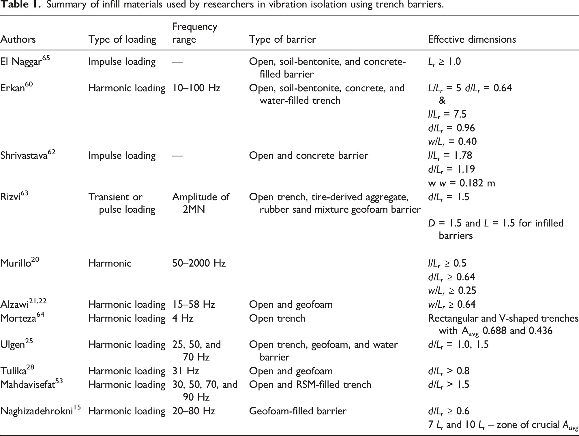
Many studies have been undertaken in the past few decades, both experimentally and numerically, to understand the vibration isolation phenomenon better. Woods 2 conducted a series of field experiments on the effectiveness of open trenches as wave barriers for active and passive isolations. They proposed that the minimum trench depth is 0.6 λ R for active isolation and 1.33 λ R for passive isolation (λR, Rayleigh wave wavelength). Haupt 3 also carried out a series of scaled-model tests in the laboratory and concluded that the reduction in ground amplitude for stiffer barriers, in general, does not depend on the actual shape of the barrier but rather on the normalized cross-sectional area. Beskos et al. 4 employed the boundary element method in the frequency domain for two-dimensional homogeneous and non-homogeneous soil conditions to study the effectiveness of vibration screening using open and infilled trenches. Later, Dasgupta et al. 5 employed this method for three-dimensional homogeneous soil conditions using open and concrete-filled trenches. Al-Hussaini and Ahmad 6 used the boundary element method to study the effect of depth, width, and material within the trench on the efficiency of open and infilled trenches in isolating harmonic vibrations. Babu et al. 7 conducted field vibration tests and 2D numerical analysis using the finite-difference tool FLAC 5.0 to study the isolation efficiency of open trenches using a gravel bed with a rubber pad and cutoff trench. It was found that the rubber pad of the proposed thickness (0.6 m) with the cutoff trench reduced the vibrations adequately. Various materials are also used as absorbing materials worldwide for vibration isolation, such as sawdust, EPS geofoam, thermocol, and shredded rubber tire chips, which are discussed herein.
Many researchers used Sawdust as a suitable absorbing medium in model and field dynamic experiments because of its high porosity that acts as an energy absorber. Stokoe and Woods, 8 Srinivasulu et al., 9 Boominathan and Ayothiraman,10,11 Boominathan and Lakshmi, 60 Chandreshekaran et al., 12 Kanaujia et al., 13 and Clement et al. 14 have used sawdust as an energy absorber associated with dynamic vibrations. The studies performed by these researchers have proved sawdust to be the most effective material for transmitting waves. EPS geofoam was also tried in the infilled trenches, and the materials were classified in terms of density and impedance ratio. EPS geofoam is an expanded polymeric material made by the expansion of raw plastic beads that is lightweight and exhibits excellent vibration damping properties. EPS geofoam inclusion within the concrete walls in the infilled trench provides attenuation against the stress waves. Naghizadehrokni et al. 15 studied the efficiency of filled geofoam barriers through field experiments and comprehensive numerical modeling. It was observed that the depth of barrier (≈ 1.0 L r ) results in efficient vibration reduction. Huang et al. 16 conducted field experiments to evaluate the efficacy of open trenches and periodic barriers. The results indicate that the efficiency of barriers is largely governed by the exciting frequency and the direction of vibration. Pubudu 17 studied the effect of the open trench and other infilled barriers such as coal bottom ash, expanded polystyrene, and water barriers under impulse loading. It was observed that the efficacy of open trenches is far better than all infilled trenches. The coal bottom ash significantly reduced the vibration along the vertical and longitudinal direction, whereas it is less effective in the transverse direction. Many studies have also been done on the positioning and placing the geofoam inside the concrete and the decay of pressure waves inside the geofoam.18–19 Such barriers are also used to protect underground structures against blasting shock waves. 18 It can also be used for thermal insulation and absorb energy from blasting or seismic shocks. 19 This property can be significantly enhanced by multiple inclusions of EPS geofoam in the concrete layer. The most attractive property of EPS geofoam for its use in infilled trenches is its thermal insulation property and ultra-lightweight (just 1% of the weight of soil). The Infilled trenches perform very well to screen vibrations in static moving loads (machine vibration). Wang et al.18,19 studied the effect of the inclusion of EPS geofoam to attenuate the stress waves. Murillo et al. 20 performed centrifuge tests to simulate the traffic vibration and investigate the effect of various parameters on the efficiency of expanded polystyrene EPS barriers. They observed that the influence of the barrier width is negligible at deeper depths and higher frequencies, but it becomes noticeable for shallow barriers and lower frequencies. Alzawi and El Naggar 21 studied the influence of wall geometry and location from the vibrating source for open and geofoam infilled trenches experimentally and numerically. Alzawi and El Naggar 22 numerically investigated the parametric behavior and effectiveness of the geofoam material under different loadings. They studied the behavior of the material as active and passive wave barriers in the form of box-wall, single continuous wall, double continuous, and double staggered wall systems. Alzawi and El Naggar 22 used the ANN (Artificial Neural Network) model to capture the influence of various parameters and then predict average amplitude reduction, which was then compared with the field and numerical analysis data for validation purposes. Ekanayake et al. 23 developed a three-dimensional (3D), finite element model using a finite element program, ABAQUS, to study EPS geofoam and water efficiency infilled wave barriers. It was observed that the efficiency of the barrier changes slightly with an increase in the length or width of the EPS geofoam wave barrier. Majumder and Ghosh 24 studied the application of continuous geofoam-filled barriers for vibration isolation under dynamic conditions. A two-dimensional (2D) finite element method was carried out in PLAXIS 2D for four different soil deposits with a sinusoidal constant force amplitude of 1 kN to study the effect of various parameters. It was observed that a continuous geofoam-filled trench is more effective in screening the high-frequency dynamic sources and performs better in the case of relatively stiffer soil deposits. Ulgen and Toygar 25 conducted multiple field experiments to investigate the screening effectiveness of open, water-filled, and geofoam-filled trenches. The screening efficiency of open and geofoam wave barriers was much higher than in water-filled trenches. Barbosa et al. 26 studied using Geofoam as infill material in trench barriers. Majumder et al. 27 numerically studied the vibration screening efficiency of intermittent geofoam infilled trench and the effect of various geometrical parameters such as depth, width, inclination, and frequency of the vibrating source, the density of the infilled material, and the location of the trench from the source of vibration. Tulika et al. 28 numerically studied the behavior of open and infill trenches under the impact of various geometrical and material properties to reduce ground-borne vibrations. It was observed that open trenches perform well for normalized depth, D > 0.8. The performance of infilled trenches was governed mainly by the density and the shear wave velocity of the infill materials rather than in-situ soil properties.
Thermocol is expanded polystyrene containing 98% air entrapped in its cells to withstand various kinds of load and vibrations because of its closed-cell structures. It has got two attractive properties—lightweight and thermal insulation. It can also be placed as an absorbing material for vibrations and heat. Hence, it can be placed at the base of the foundation of heavy machines to utilize its dual functional characteristics-vibration absorption and heat insulation. Reshma 29 investigated the feasibility of using thermocol as infill material in trenches for vibration isolation using field testing and concluded that thermocol could be used but indicated that the study carried out is very limited and suggested a detailed investigation. Sahu et al. 30 used thermocol as a wave absorbing medium in model vibration tests conducted in the laboratory and found it effective in minimizing the wave reflection from tank boundaries.
Waste rubber tires in different forms/shapes are being used in many geotechnical applications such as soil reinforcement, 31 ground improvement, drainage materials, backfill in 32 embankments/retaining walls, 33 liquefaction mitigation, and subgrade improvement for rural roads.34–40 Using rubber tires in different forms is classified as tire chips mixed with soil and not with soil. Cement-treated clay with tire chips possesses high ductility and toughness, making it worthwhile to reduce liquefaction potential. It is also used as a drainage material for facilitating compression and consolidation of volcanic-ash-based clayey soils on highway embankment to protect against frost heave in subgrades and side ditches of highways in cold regions or at mountainous sites. 41 Tweedie et al. 42 conducted a full-scale test to investigate the feasibility of tire shreds as retaining wall backfill. Ghazavi and Sakhi 43 studied the influence of the aspect ratio of waste tire shreds on shear strength parameters of sand reinforced with shredded waste tires. They conducted large direct shear tests on sand alone and sand shred mixtures and found that Mohr envelopes were nonlinear in almost all soil-shred combinations and the tire shreds increased friction angle by 10 – 90%.
Rubber is also an energy absorber but acts differently from sawdust.44–47 The feasibility of using rubber chips to control soil liquefaction and isolate earthquake-induced vibrations has been explored. Kaneko et al. 48 tried two alternatives for liquefaction potential. They tried mixes of saturated sand and shredded rubber tires and placed them in two alternate layers. They investigated that when tire chips are placed at the bottom, liquefaction is not generated in the upper layer because the amplitude of seismic waves was attenuated.
Tire chips installed as a layer were more effective when placed at deeper locations. The above workers showed that horizontal and vertical vibrations resulting from earthquakes were reduced by 80%. Bahadori and Manafi 49 demonstrated that the excess pore water pressure ratio and liquefaction settlement decreases significantly by increasing the percentage of tire chips. It was also found that the mean damping ratio increases with increasing tire chip content in the sand tire chips mixture. Bahadori and Farzalizadeh 50 also studied the effect of saturated sands mixed with tire shreds and tire powders on the liquefaction potential. They observed that the mean damping ratio decreases as the tire shred content increases more than 10%. The tire shreds and tire powders reduce the mixture settlement caused by liquefaction. Madhusudhan et al. 51 studied the static and dynamic properties of sand-rubber tire shred mixtures for seismic isolation of low-rise buildings. Strain-controlled undrained triaxial tests and strain-controlled cyclic triaxial tests were carried out for static and dynamic characterization of sand mixed with variable rubber contents. This phenomenon demonstrates that the tire chips/powders have a perfect energy-absorbing capacity and can be effectively used in vibration isolation problems.
Summary of infill materials used by researchers in vibration isolation using trench barriers.
This paper investigates the parameters affecting the performance of open and infilled trench barriers with sawdust, EPS geofoam, and shredded tire chips. The high energy-absorption capability and economically efficient shredded tire chips are alternatives in various geotechnical fields. Therefore, the present study analyzes the isolation efficiency of trench barriers filled with shredded tire chips and their performance compared with other infill materials such as EPS geofoam and sawdust. The numerical study has been undertaken to find their efficiency as an infill material and understand the effect of crucial geometrical parameters, such as trench depth, location, soil medium, and frequency of the vibrating source, on infilled and open wave performance barriers/trenches.
Numerical modeling
The screening performance of open and infilled circular trenches excavated in a homogeneous half-space has been analyzed under the axisymmetric condition using PLAXIS 2D.54–55 Radiation damping is overestimated in a two-dimensional (2D) approximation of a three-dimensional (3D) problem and may introduce potential errors in the results. The 3D cases are often reduced to 2D problems using either plane-strain or axisymmetric conditions, especially in vibration isolation cases. Beskos et al.
4
and Dasgupta et al.
5
studied the subject of active isolation using Green’s function for open trenches. They found that the 2D model gives a conservative estimate compared to a 3D model with a 10–15% error. Alzawi and El Naggar
22
used a 2D FEM and found an average discrepancy of 10–15% in amplitude reduction factor compared to full-scale experimental results when estimating the effectiveness of open trenches, which is quite acceptable. A vertically vibrating source of magnitude F
0
and frequency (f) is assumed to act as a distributed load over a footing of size 1 m (0.5 m for an axisymmetric model). The schematic of the vibration problem considered for the analysis is shown in Figure 1(a). (a) Problem definition for the analysis. (b) Typical 2D numerical model developed for vibration isolation problem in PLAXIS 2D.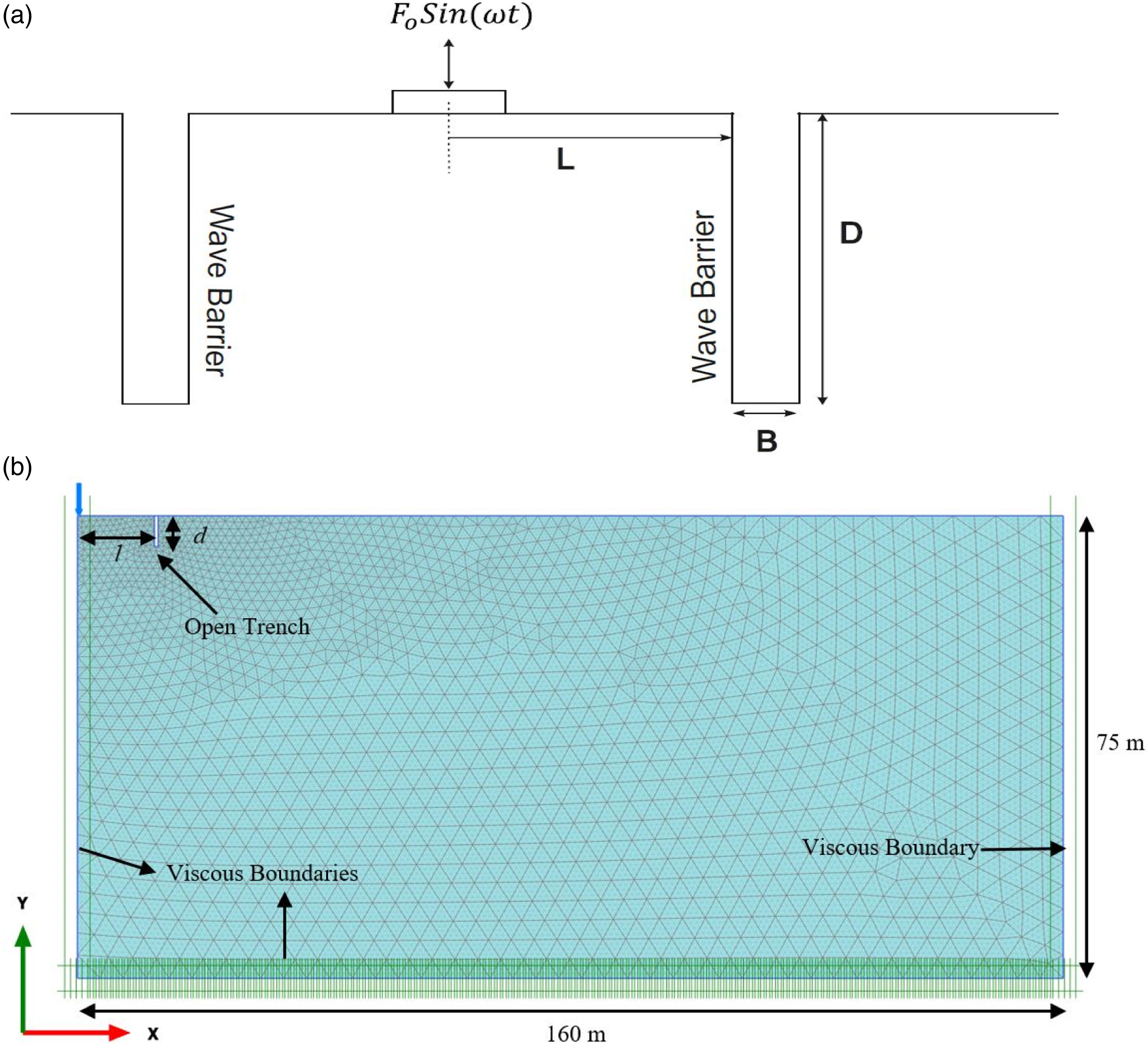
Details of modeling
A numerical model is developed, and the problem is simulated in PLAXIS 2D to understand the behavior and isolation efficiency of open and infilled trench barriers. The 2D axisymmetric model with 15 node triangular elements is used, and the model dimensions are kept at 160 m × 75 m. Standard fixities are assigned to the model boundaries. The special boundary conditions are specified at the bottom and right boundaries to avoid spurious reflections since the soil is a semi-infinite medium, and without special boundary conditions (u x = u y = 0), the waves will be reflected at the model boundaries, causing perturbations. The typical FE model in PLAXIS 2D with the boundary conditions is shown in Figure 1(b). The wave absorption on the absorbent boundaries is improved by introducing wave relaxation coefficients C 1 and C 2 . The coefficient C 1 improves the wave dissipation in a direction normal to the boundary, and C 2 does in the tangential direction. In the present analysis, PLAXIS 2D default values C 1 = 1 and C 2 = 0.25 are used.19,55 The length of the model is kept somewhat higher than the crucial zone of screening (i.e., 10λ). Although special measures are adopted to avoid spurious reflections, minor influence is always possible. It is an excellent practice to keep the model boundaries far away from the region of interest.
The soil half-space is modeled as a linear elastic, isotropic, and homogeneous medium as the associated strain levels caused by wave propagation in the soil are very small. The soil volume is modeled using 10-node tetrahedral elements available in the PLAXIS 2D library with a total number of model elements of 3751 and 30,439 nodes. The mesh discretization is done with very fine elements, and local refinements are done around the edges and along the surface of the trenches. The relative element size for fine mesh is 0.03. The time interval for dynamic analysis is taken as default values of additional steps (n), and dynamic sub-steps (m) are 250 and 4, respectively, for which the time-step of integration
The unit weight (γ) and Poisson’s ratio (ν) of the soil are assumed for the Delhi Silt (Sandy Silt) as 17.5 kN/m3 and 0.3, respectively, for all the cases. The peak velocity amplitudes are calculated from velocity-time histories at selected nodes in vertical directions. The mass of the foundation is neglected in the analysis as the previous work by Beskos et al., 4 based on numerical analysis, reported that the effect of foundation mass is insignificant by calculating ARF. The amplitude reduction factor is the ratio of peak velocity amplitudes with and without a barrier at a certain point.
Material damping of 5% is introduced into the soil, and Rayleigh coefficients are computed from their relationship, α + βω2 = 2ζω, with the angular frequency of the excitation (ω) and material damping (ζ). For a given model of height H, the fundamental angular natural frequency of the medium is provided as
Initial Stage: The initial vertical and horizontal effective stresses are calculated using K0 procedure under the influence of self-weight of the material considering the loading history of the soil.
Stage 1: The rigid disk is installed, and the loading is applied.
Stage 2: The trench is excavated; model (absorbent) boundary conditions are applied at the bottom and sides of the soil model. The mesh calculations are carried out with very fine elements around the trench and near the surface.
Stage 3: The dynamic analysis is carried out by applying the dynamic load to the disk for different operating frequencies maintaining the material damping of 5%. The dynamic time interval is defined for Max steps and number of sub-steps.
Final Stage: The calculation procedure takes place for the entire model including the dynamic analysis.
Validation of the finite element model
The accuracy and validity of the numerical model were confirmed by comparing the results obtained from the experimental work with previous findings obtained by.6,22 In the validation in Case 1: Al-Hussaini and Ahmad, 6 as the passive isolation problem is considered, the model is regarded under plain strain, whereas, for validation in Case 2: Alzawi and El Naggar, 22 the axisymmetric model is considered in the finite element analysis.
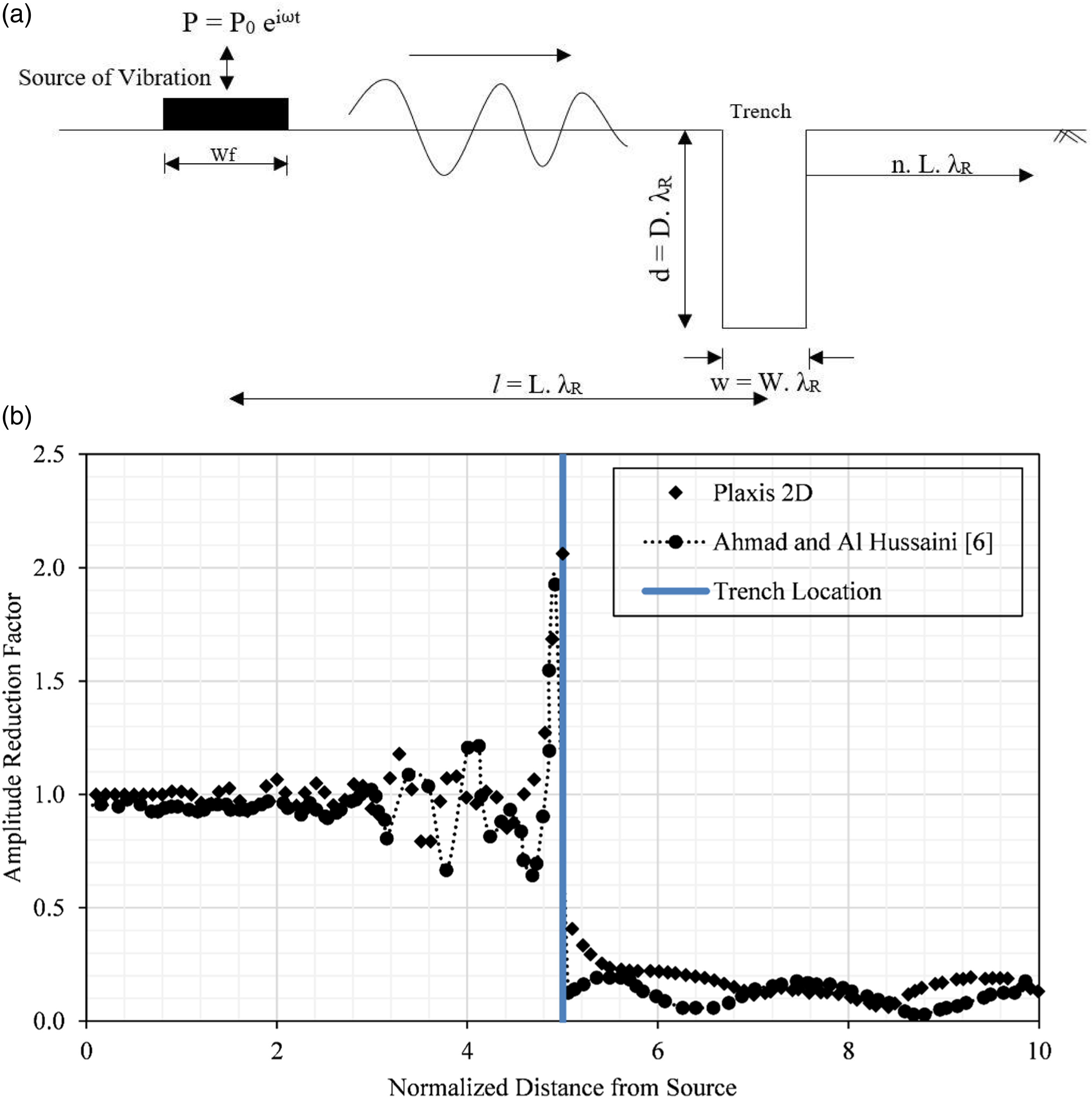
The problem of passive isolation under plane-strain conditions using a rectangular open trench is considered. Analysis has been carried out for other distances, and similar results are obtained. The schematic representation of the vibration problem considered for the validation is shown in Figure 2(a). Since vibration isolation by a trench is primarily achieved by screening surface (Rayleigh) waves, the depth, width, and distance of the trench are normalized concerning the Rayleigh wavelength (D = d/λ
R
, W = w/λ
R
, L = l/λ
R
where λ
R
= Rayleigh wavelength). The presence of a trench causes a reduction in the vibration amplitude in an area behind the trench. The screening effect is expressed by the parameter A
r
(Amplitude reduction ratio), that is, where (A
r
)
After
is the vertical displacement amplitude of ground surface with the barrier and (A
r
)
Before
is the vertical displacement amplitude of ground surface without the barrier In the present analysis, the soil (Delhi Silt) is considered, and the soil properties for the Delhi Silt were adopted from Shahu et al.
24
and Tandon et al.
56
The source has a frequency of 50 Hz. The problem is simulated in PLAXIS 2D as a plain-strain problem with 15 node triangular mesh elements. The model dimensions were kept at 60 m × 25 m. Absorbent boundary conditions are specified to avoid reflections of waves as the soil is assumed to be a semi-infinite medium. The mesh discretization is carried out with very fine elements. The time interval for dynamic analysis is taken as 0.5 s, which is enough to permit the complete passage of the waves in the zone of investigation. Vertical ground amplitude is measured along the length of the model before and after installation of the open trench at 5λ
R
from the source, where λ
R
is the Rayleigh wavelength (λ
R
= V
R
/f). The variation of Amplitude reduction ratio (A
r
) predicted by Finite Element (FE) analysis is plotted with normalized distance, as shown in Figure 1(b). The experimentally measured A
r
values reported by Al-Hussaini and Ahmad with distance are also superimposed in Figure 2(b). It is observed from Figure 1(b) that the horizontal distance of points is normalized concerning Rayleigh wavelength, and results obtained from FE analysis closely match the results measured by Al-Hussaini and Ahmad.
6
This confirms that the procedure adopted in FE analysis can simulate the attenuation of waves.
A vertically vibrating source generating a sinusoidal source of magnitude (P
0
= 23.5 kN peak to peak) and frequencies (f) of 40 and 50 Hz is assumed to act as a distributed load over a massless footing with a width of 0.75 m (0.375 m for an axisymmetric model). The half-space is supposed to be linearly elastic, isotropic, and homogeneous. The schematic representation of the vibration problem considered for the validation is shown in Figure 3(a). The soil density (ρ) varies between 1812.5 and 1955.3 kg/m322 and Poisson’s ratio (ν) of 0.4, respectively. The shear wave velocity varies from 225 m/s to 455 m/s for the depth of 30 m. The material damping (ζ) of the soil is assumed to be 5%. The variation of predicted and measured normalized soil particles velocities with distance from the source of disturbance for Case 2 is shown in Figures 3(b) and (c), respectively, for different excitation frequencies. It is evident from Figures 3(b) and (c) results from the FE analysis follow the trend of experimental results obtained by Alzawi and El Naggar.
22
It is also observed from Figures 3(b) and (c) that as the distance from the source of disturbance increases, FE results show slightly higher values at some locations and lower values at others, as obtained by Alzawi and El Naggar.
22
This may be due to the local soil inhomogeneities induced in the field due to large cobbles during trench excavation.
22
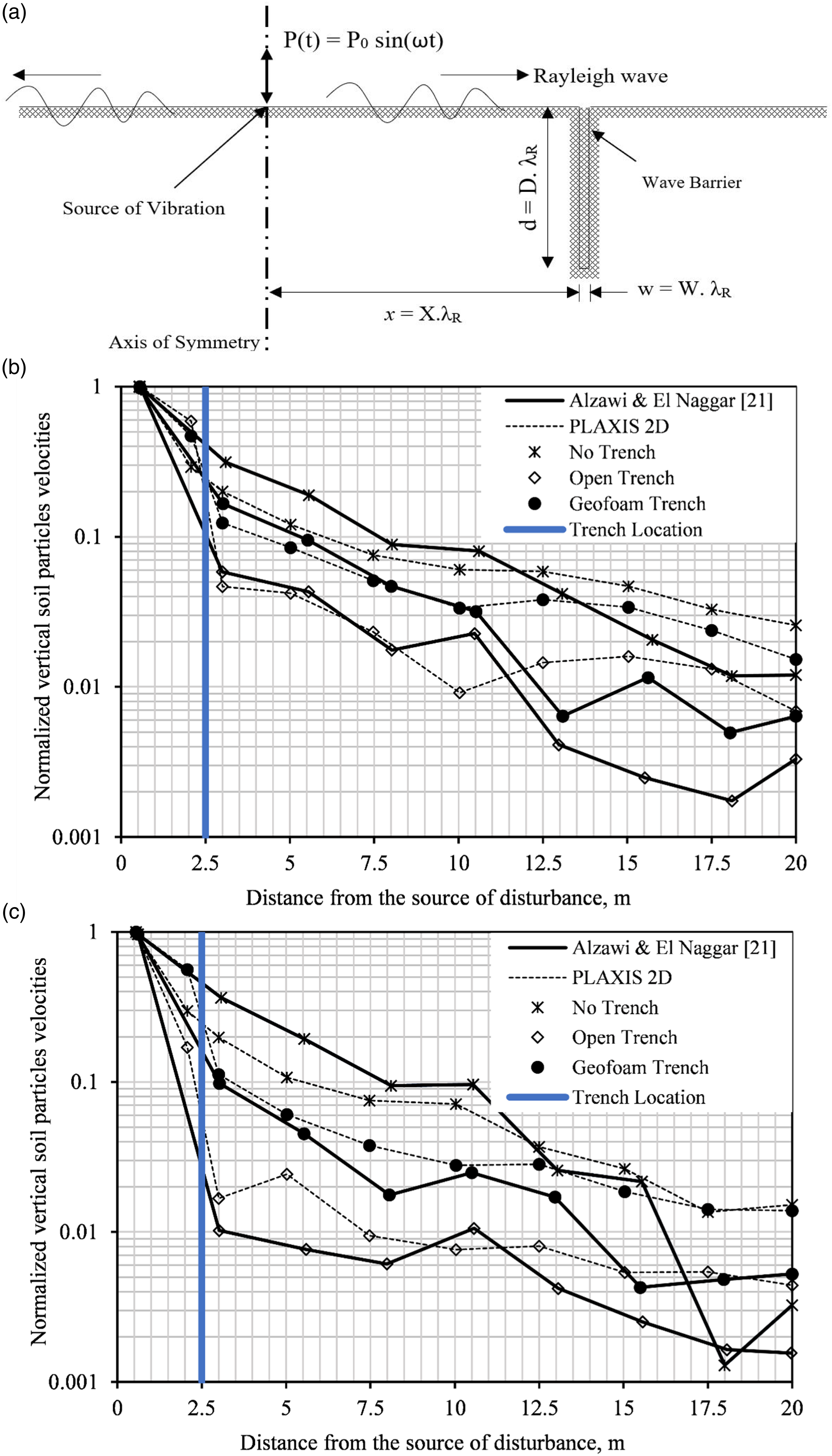
(a) Schematic of vibration problem considered for the validation of experimental results reported by Alzawi and El Naggar 21 using PLAXIS 2D. (b) Comparison of simulated normalized vertical soil particles velocities with measured values computed by Alzawi and El Naggar 21 for exciting frequency 40 Hz. (c) Comparison of simulated normalized vertical soil particles velocities with measured values computed by Alzawi and El Naggar 21 for exciting frequency 50 Hz.
Parametric study
Validation problems analyzed for two cases indicate that modeling the vibration and its attenuation using PLAXIS 2D is adequate and can be reliably used to extrapolate the results. Considering a similar modeling procedure, a parametric study is carried out for open and infilled trench barriers under axisymmetric conditions. A harmonic load of magnitude 1 kN/m acting over a width of 0.5 m is considered in the analysis. The schematic representation of the vibration problem considered for the study is shown in Figure 1(a).
Properties of infill materials.
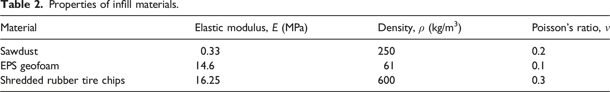
Relation between different parameters considered in the analysis.
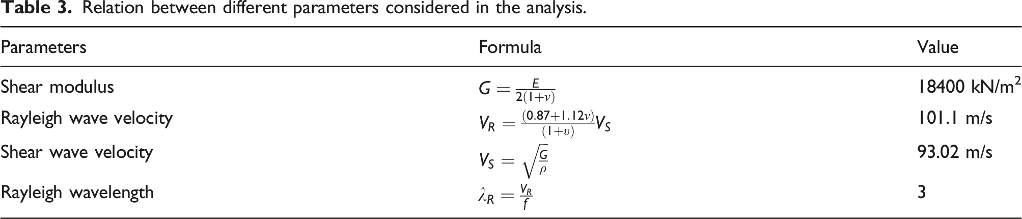
(a) Flow chart representing various infill materials and parameters considered in the numerical analysis. (b) Convergence Study for (1) Vertical Displacement and (2) Vertical Velocity.
The minimum length of the model is adopted as 10 λ R as the crucial zone lies within 10 λ R from the source. The maximum size of the model is found by varying values of V R of the soil and frequency of the origin such that we get maximum values of λ R . For the given range of V R and f, maximum values of λ R are obtained when V R is maximum, and f is minimum, that is, V R = 300 m/s and f = 20 Hz. Thus λ R = 15m, which results in the minimum length of the model as 150 m. The distance of the right model boundary from the source is kept somewhat higher to avoid any undue reflection despite using absorbent boundary conditions. A convergence study is carried out to decide a suitable overall length of the model after several attempts on the trial lengths for the present study. The trial lengths of 160 m and 170 m were decided based on minor errors. A trial model depth (H) of 5 λ R = 75 m is considered for all these analyses. An undisturbed half-space (without a barrier) with the above soil parameters is subjected to a steady-state harmonic disturbance of magnitude and frequency. The amplitudes of vertical components of surface displacements and velocity are plotted against normalized distances from the source (X = x/λ R ), as shown in Figure 4(b). It is observed that the displacements and velocity amplitudes show convergence. So, the length of the model is fixed at 160 m for all the subsequent studies (for all variations of V R and f, as the maximum value of λ R is used to get this length).
Similarly, the convergence study is carried out to determine a suitable depth of the model. The depths of the model are taken as 5 λ R , 6 λ R, and 7 λ R (i.e., 75 m, 90 m, 105 m). They also showed convergence and gave an exactly similar plot (hence have not been included again), and thus the size of the model is fixed as 160 m × 75 m.
Results and discussions
The ground vibrations affecting the structures can be resolved in three mutually perpendicular directions, longitudinal, transverse horizontal, and transverse vertical. The transverse horizontal component is usually much smaller than the longitudinal and transverse vertical components and is comparable in magnitude. The parameters associated with ground particle vibrations are acceleration, velocity, displacement, and their respective frequencies. It is observed from the convergence study, as seen in Figure 4(b), that the peak ground particle velocity at the surface is more than the surface displacement. It is also to be noted that the safety of adjoining structures to ground-borne vibrations is assessed by peak particle velocity (PPV).58,59,24 Hence, PPV represents an excellent general index for evaluating the damage. In this study, the parametric study results are expressed as an average reduction in the vibration amplitude in terms of PPV for assessing the efficiency of the trench barriers.
Effect of infill materials
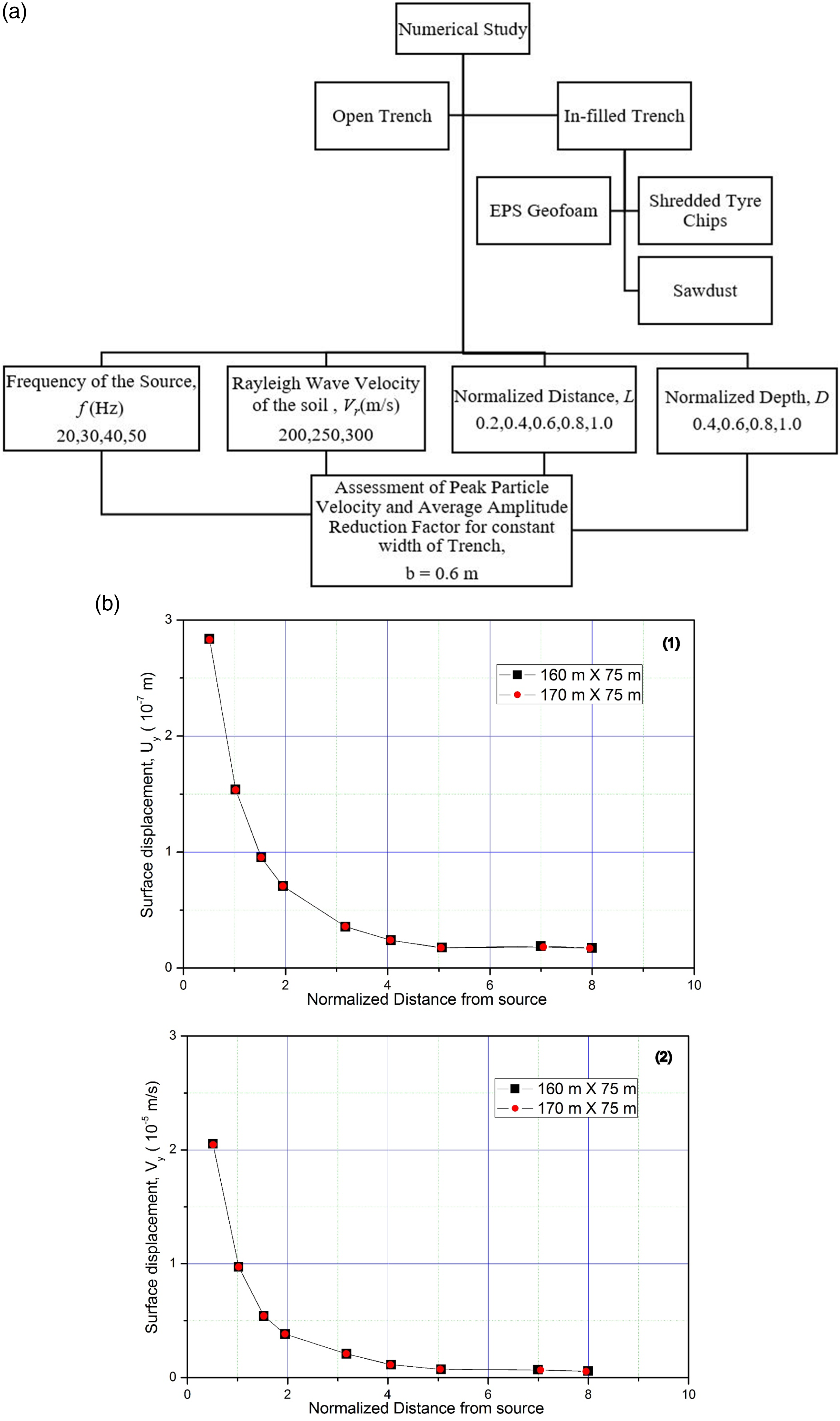
There are different approaches to deriving PPV, and it is approximately equal to the peak value of the velocity in the vertical direction. The PPV at various points is determined and normalized concerning the PPV value at the source. The normalized PPV (PPV*) variation is then plotted concerning the normalized distance to find the decay in the vibration amplitude. Various parameters, like the normalized depth of trench (D), a normalized distance of the trench from the source (L), the frequency of the vibrating source, different soil mediums, and different types of infill materials, have been considered in this study. The typical variation of PPV concerning normalized distance from the source for other fill materials is shown in Figure 5 for the different frequencies of the vibration source. It is inferred from Figure 5 that all infill materials used in this study perform efficiently in isolating ground vibrations. Sawdust as fill is found to perform well in an open trench; that is why sawdust has been used as vibration absorption/isolation material for many decades.8–14 The PPV of EPS-filled and tire chips–filled trenches is similar but slightly higher than the open and sawdust-filled ones. Normalized Vertical peak particle velocities for V
R
= 250 m/s and for L = 1.0 and D = 1.0: F = 20 Hz; (b) F = 30 Hz; (c) F = 40 Hz; (d) F = 50 Hz.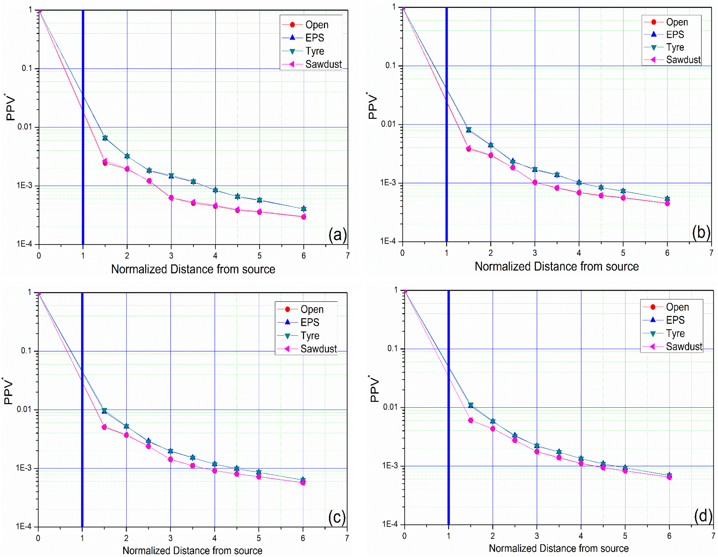
Nevertheless, the efficiency of these fill materials is within acceptable limits. This confirms that waste shredded tire chips can also be used as effective infill material. It is also observed from Figure 6 that the vibration becomes less than 0.5% after 3 λ
R
. Therefore, the average amplitude reduction factor is computed up to this point behind the trench; after that, the variations are insignificant. Variation of V
R
with source frequency for different infill materials: (a) Open, (b) sawdust, (c) EPS geofoam, and (d) shredded tire chips.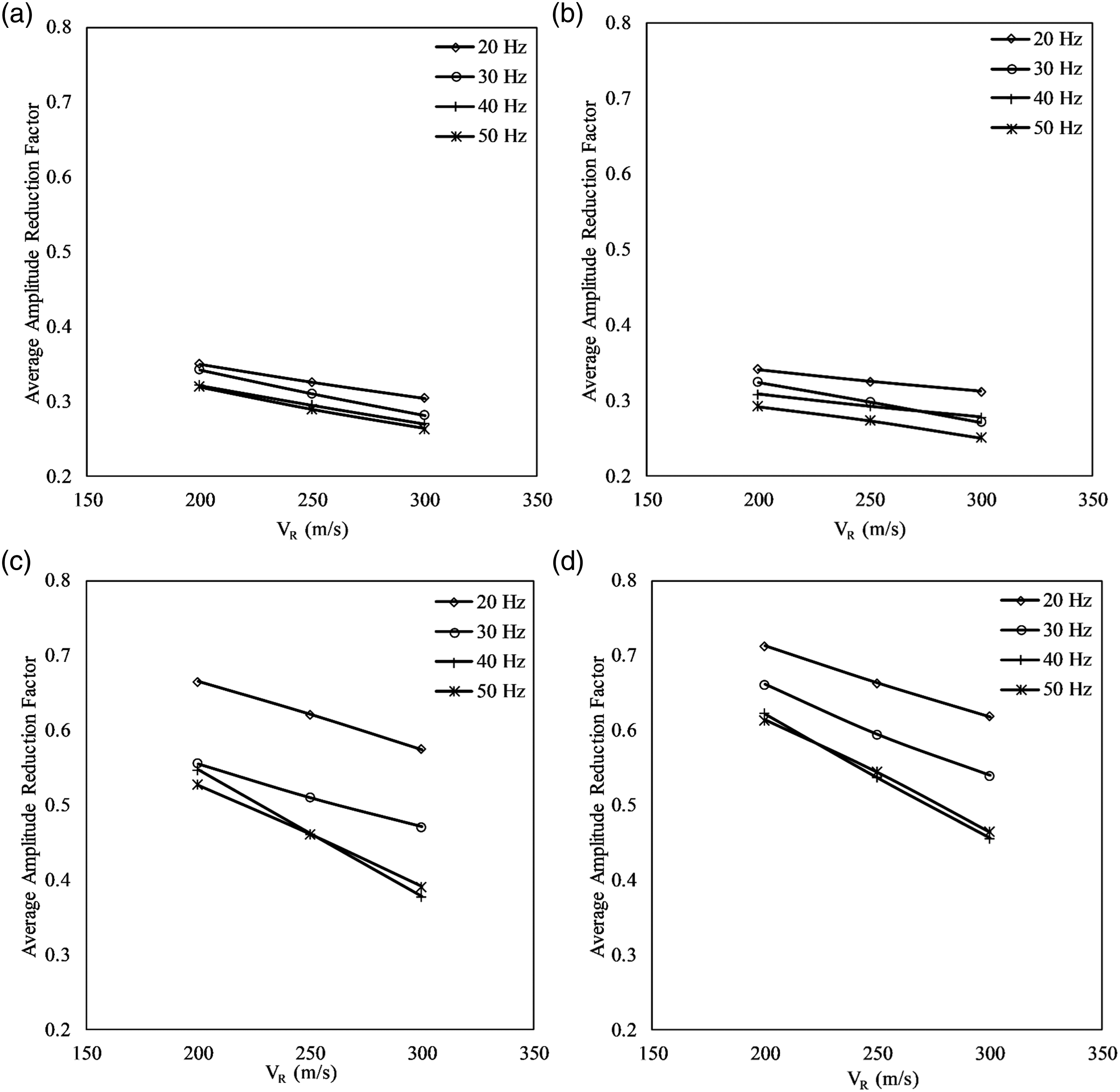
Effect of trench dimensions
Amplitude reduction in the velocity (ARF) is obtained by normalizing the vertical velocity component of vibration after the installation of the trench by the vertical velocity component of vibration before the installation of the trench. The maximum value of the velocity amplitude is used from the time history of the vibrations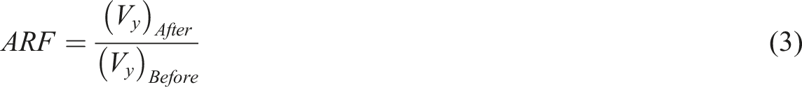

The typical variation of V
R
with L and D for open and infilled trenches is shown in Figures 7–10, respectively. These curves are given for a typical shear wave velocity of the ground at 250 m/s, although the analysis is carried out for different shear wave velocities of the ground. From the curves obtained, it is observed that when the depth of the trench increases or the distance from the trench increases, the average amplitude reduction factor reduces, that is, the efficiency of the wave barrier increases. The effects of depth and distance are even more pronounced when both increase simultaneously. The average amplitude reduction factor decreased in the range of 1–48% with the varying trench dimensions for EPS geofoam and tire chips–filled trenches. However, the reduction in amplitude was in the range of 10–60% for open and sawdust-filled trench barriers. Variation of V
R
with L and D for open trench for V
R
= 250 m/s and different excitation frequency (a) F = 20 Hz; (b) F = 30 Hz; (c) F = 40 Hz; (d) F = 50 Hz. Variation of V
R
with L and D for sawdust-filled trench for V
R
= 250 m/s and different excitation frequency: (a) F = 20 Hz; (b) F = 30 Hz; (c) F = 40 Hz; (d) F = 50 Hz. Variation of V
R
with L and D for EPS geofoam trench for V
R
= 250 m/s and different excitation frequency: (a) F = 20 Hz; (b) F = 30 Hz; (c) F = 40 Hz; (d) F = 50 Hz. Variation of V
R
with L and D for tire infilled trench for V
R
= 250 m/s and different excitation frequency: (a) F = 20 Hz; (b) F = 30 Hz; (c) F = 40 Hz; (d) F = 50 Hz.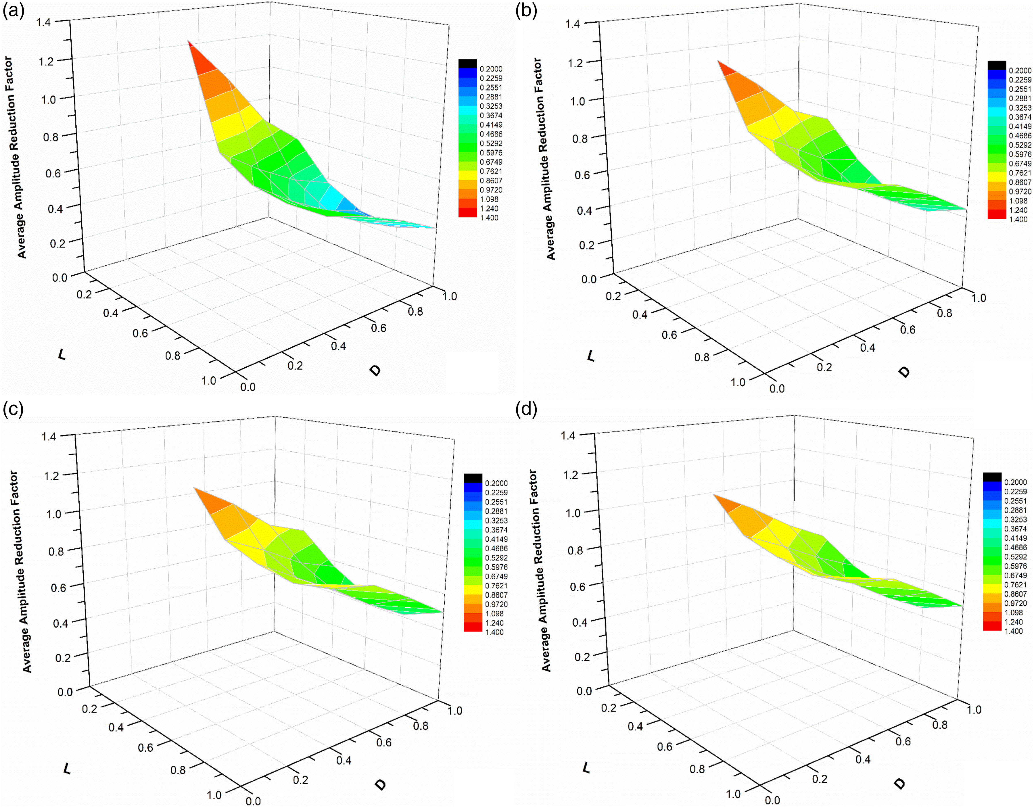
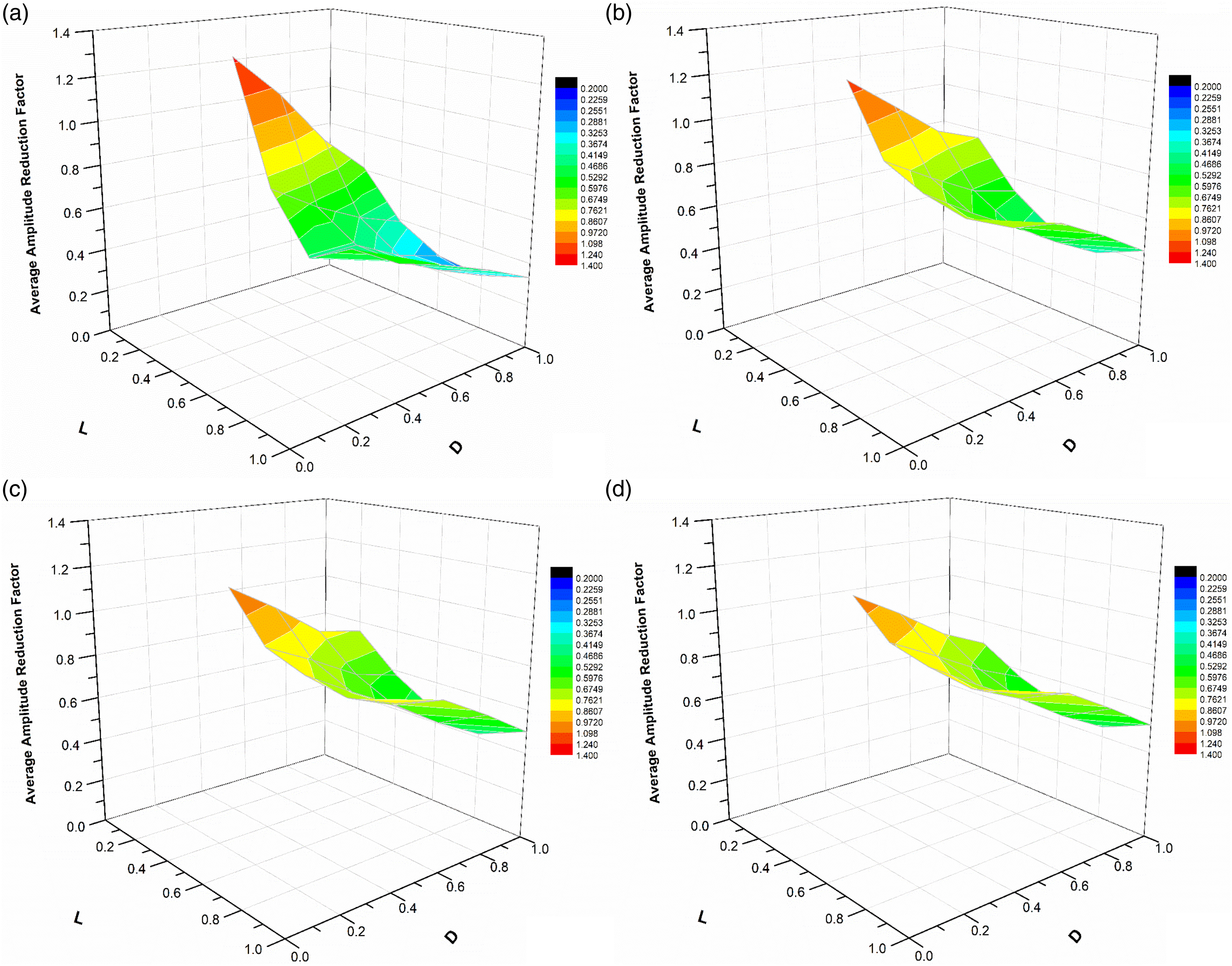
When the trench is very close to the vibrating source, there is almost no isolation effect due to the trenches. This is due to the very complex nature of wave propagation as the body waves are predominant near the source. A significant part of the vibration energy induced by dynamic sources transferred by the Rayleigh waves propagating in the region near the soil surface may cause strong ground motions and stress levels transmitting vibrations through the sub-soil to the structures. Therefore, the permanent adverse effects of these excessive vibrations on the foundations, notably supported on the soft soil deposits, cause structural damage to the adjacent structures. The shallow depths of trenches (D = 0.2, 0.4) are ineffective in isolating this vibration energy. The maximum reduction factor is obtained for trenches at L = 0.8 and L = 1.0 for D = 1.0. With the increasing depth of the trench, the isolation efficiency of the trench also increases. Open trenches give a maximum reduction in vibration energy, that is, minimum average amplitude reduction ratio. A trench-filled with different infill materials shows a relatively slighter amplitude decrease than an open trench. Nevertheless, infilled trenches also effectively reduce the amplitude for similar trench dimensions.
Effect of ground stiffness
The typical variation of the average amplitude reduction factor with the shear wave velocity of the ground (referred to as ground stiffness) for different infill materials is shown in Figure 6, as it is evident that with an increase in the stiffness of the ground, the amplitude of vibration will decrease, even for the constant damping values. The same is observed in the response predicted by the present analysis, as shown in Figure 6. However, in Figure 6, the rate of reduction in ARF with the shear wave velocity is different for various infill materials used. The percentage reduction in the average amplitude reduction factor is in the range of 4–9% for open and sawdust-filled trench barriers, whereas it is 6–18% for EPS geofoam-filled and tire chips–filled trench barriers. This shows that the behavior of open and sawdust-filled trench is similar for varying ground stiffness. Similarly the behavior of EPS geofoam-filled trench is similar to shredded tire chips–filled barriers. This might be due to the stiffness contrast between the natural ground and infill material and different damping values in the 5–15% range.
Comparison with previous studies
Results obtained from the numerical analysis in this study were then compared with those published in the literature. The normalized distances in those studies range from L ≈ 0.4–1.5 for Tulika et al.
29
to L ≈ 0.4–1 for Alzawi and El Naggar.
22
Beskos et al.
4
reported that the distance between the source of vibration and the trench location has almost no effect on amplitude reduction. Therefore, the variations of average amplitude reduction ratios were plotted concerning D for open and infilled trenches, as shown in Figures 11 and 12. Figure 11 shows the comparison between the present study and estimated results by Tulika et al.,
29
Ahmad and Al Hussaini,
6
Alzawi & El Naggar,
22
and Saikia and Das
61
for an open trench concerning the normalized depth of the trench. It is observed from the figure that amplitude reduction values for open and geofoam-filled trench lie in the range of 0.2–0.4 for L ≥ 0.4, which signifies that the location of the trench from the vibration source has significantly less influence on the amplitude reduction values. It can be deduced from Figure 12 that the amplitude reduction values for EPS geofoam-filled trenches estimated by Tulika et al.
29
are closer at smaller distances, whereas, Alzawi & El Naggar gives higher reduction values as compared to the present study. It is also observed from the current numerical analyses that the vibration isolation efficiency of shredded tire chips is similar to the EPS geofoam. Hence, shredded tire chips can also be used as a vibration isolation material in infilled trenches. Comparison of the average amplitude reduction ratios obtained from this study with the reported literature for open trench. Comparison of the average amplitude reduction ratios obtained from this study with the reported literature for EPS geofoam-filled trench.
Conclusions
Numerical analyses have been carried out using PLAXIS 2D to conduct an extensive parametric study on the active isolation of vibrations by open and infilled trench barriers. Sawdust, geofoam, and shredded tire chips are considered infill materials. The following are the significant conclusions arrived at from the parametric study: 1. The normalized depth D for maximum screening efficiency depends on the normalized distance of the trench from the source. It is noted that with an increase in normalized depth, D, the averaged amplitude reduction ratio decreased, which means the protective system effectiveness is very good for higher normalized depth. The results significantly improve when the normalized depth is greater than or equal to 0.6 times the Rayleigh wavelength (λ
R
) for open and infilled trenches. 2. The open and sawdust-filled trenches show similar isolation efficiency as seen in Figure 6, whereas the geofoam-filled and shredded tire chips–filled trenches show similar isolation efficiency. The results of the present study are consistent with the results reported in the literature. The study confirms that the shredded tire chips can also be used as an infill material in trench barriers. As observed in the study, the barrier protective effectiveness of shredded tire chips was up to 65% or higher and hence can be considered a practical alternative for vibration screening. The most important parameter governing the efficiency of an infill trench is the density and shear wave velocity of the infill material compared to the surrounding in-situ soil. 3. As seen from Figures 11 and 12, the results obtained from the FE model are in close agreement with previously published experimental and theoretical results. Hence, the developed FE model can adequately represent the vibration isolation problem for both open and infilled (Shredded tire chips) trench barriers and can be used to extrapolate the results. The developed FE model can design/evaluate open or infilled trench wave barriers for vibration isolation for other soil conditions.
In summary, the findings of this research can be applied to different ground conditions for designing the optimum trench concerning its depth and width. However, field experiments may be carried out to verify the actual efficiency of other infill materials in various ground conditions.
Footnotes
Declaration of conflicting interests
The author(s) declared no potential conflicts of interest with respect to the research, authorship, and/or publication of this article.
Funding
The author(s) received no financial support for the research, authorship, and/or publication of this article.
Notes
1Kavita Tandon, Senior Research Fellow, Department of Civil Engineering, IIT Delhi - 110016