
Abstract
Planetary reducer box undertakes the vibration transmitted from gear transmission system to bearing, and further transmits the vibration to the base. Research on the transmission path contribution of reducer box has an important guiding role in reducing vibration. This paper first analyzed the contribution of each vibration path of the gearbox based on the velocity intervention loss, so as to identify the main transmission path of the gearbox vibration; then the vibration test of the gearbox is carried out to verify the correctness of the transmission path model. The results show that the vibration transmission path of the right bearing of the gearbox is the main transmission path, and the established vibration transmission path dynamics model of the gearbox can well reveal the contribution law of the vibration transmission path of the gearbox.
Planetary reducer has been widely used in aircraft, ships, and other fields due to its good transmission stability and compact structure.1–2 At present, the planetary reducer is developing in the direction of high speed, high power, light weight, and low noise, which puts forward higher requirements for the vibration and noise of the gearbox. Therefore, there is an urgent need for scientific and technical personnel to take various means to achieve vibration and noise reduction of marine gearbox.3–4 In the reducer box, harmful vibration will be generated when the transmission system is excited by time-varying stiffness and tooth profile error, and will be transmitted to the base along different paths.5,6 Therefore, it is necessary to study the contribution of vibration transmission path of planetary reducer box.7–9
Domestic and foreign scholars have carried out research on vibration transmission path of gearbox structure. SEA, namely, Statistical Energy Analysis, is the first proposed method to analyze the characteristics of transfer paths. According to the principle of statistical energy analysis, Xiufang Zhang 10 studied the estimation method of loss factor of gear shaft-rolling bearing-plate coupling structure and studied the characteristics and influencing factors of vibration energy transmission through rolling bearings. The statistical energy method is suitable for structural high-frequency acoustic vibration analysis, but it can only obtain the statistical average of each subsystem, and the workload of this method is very large. At present, the development of SEA is limited by a series of assumptions.
Power flow method not only takes generalized force and generalized velocity as the research variables in transmission path analysis, but also converts the difficult vector operation in traditional transmission path analysis into relatively easy scalar addition and subtraction. This method is gradually being paid attention to by researchers. Yang 11 deduced the power loss formula of each coupling point of the gearbox based on hypergraph and matrix theory. Wenguo Qi 12 studied the transmission characteristics of vibration energy of gearbox structure by substructure admittance method with power flow as the evaluation method. The results show that the vibration energy generated by gear meshing is almost all transmitted to the gearbox. Weibo Zhang 13 used the substructure admittance method to establish the structural acoustic power flow transfer model of gearbox-like complex coupling system, and quantitatively analyzed the power flow that caused the lateral vibration of the box wall. Pinington 14 studied the transmission of power flow generated by the plane force on the gear edge to the gearbox based on the substructure admittance method. Substructure admittance method only needs to care about the solution of velocity and force at the input and output ends of each subsystem, without considering the internal mechanical behavior. At present, this method is widely used in the field of vibration.
With the development of computer technology, many scholars began to combine the finite element analysis and power flow method, forming the finite element power flow method. Li Du 15 established the finite element model of gearbox system and studied the transmission characteristics of vibration power flow under given external excitation. Qiuhong Li 16 analyzed the structure of double-axis turntable by finite element power flow method, and identified the main vibration source and main transmission path. Hongyin Dou 17 used the finite element power flow as the evaluation method to quantitatively analyze the vibration contribution of the transmission path from the fault signal of the wind turbine gearbox to the sensitive measuring point. The finite element power flow method is simple and accurate, which is the main method to study the contribution of vibration transmission path of gearbox structure. However, it usually requires a specific gearbox model, which is only suitable for the analysis of the contribution of transmission path in the later design stage.
The transfer path dynamic model of complex mechanical structure can be established by the lumped parameter method, and the contribution of the transfer path can be obtained. It is also suitable for the early and late design and has been widely used in many fields. Janssens 18 proposed a parametric transfer path model, using mathematical methods to eliminate noise interference during testing. Zhang 19 established a two-degree-of-freedom vibration model of hydraulic pump and obtained the vibration mode and steady-state response of hydraulic pump. Linxiao Quan 20 swash plate box of swash plate axial piston pump as the final receptor of vibration transmission, analyzed the contribution of transmission path with force transmission rate as the evaluation index, and carried out experimental verification. Wei Zhao 21 studied the contribution of the vibration transmission path of the automobile system with the force transmission rate as the evaluation index and analyzed the sensitivity of the frequency domain response of the system parameters.
Considering the uncertainty of mass, damping, stiffness, and other parameters, Baoping Zhi 22 used the random parameter structure analysis method to give the radial vibration path transmissibility and transmissibility variance of the Francis turbine. Yimin Zhang23–25 solved the problem of uncertain vibration transmission path better through the random response analysis of vibration transmission path system in time domain; and then, he proposes a new concept of path transmission degree to solve the problem of measuring the transmission probability of vibration and noise in time/frequency domain. Hao Cao 26 studied the vibration transmission path of torpedo power cabin based on the concept of intervention loss. Jianwei Liu 27 identified the contribution of the fluid vibration transmission path of the swashplate axial piston pump through the method of velocity intervention loss, built the axial piston pump test bench, and verified the correctness of the theoretical model according to the vibration acceleration response results. The above research mainly analyzes the contribution of the transfer path by establishing a transfer path dynamic model and does not verify the contribution analysis results based on experiments.
In this paper, the planetary reducer box is taken as the research object, and the vibration transmission path model of the reducer box is established by using the vibration transmission path method. After the model parameters are determined by the numerical simulation method, the dynamic model is solved, and the path contribution of the vibration transmission path system is analyzed from the perspective of the velocity intervention loss of the path, and the main transmission paths are identified. Finally, the contribution test is carried out to verify the calculation results of the dynamic model.
Contribution analysis of vibration transmission path of planetary reducer box
Contribution analysis of vibration transmission path of planetary reducer box
The three-dimensional model of planetary reducer box is shown in Figure 1. The planetary reducer is mainly composed of left box, middle box, right box, left bearing, right bearing, and planetary carrier. The middle box is connected with the base, so the vibration of the reducer is transmitted to the base through the middle box, so the middle box is a vibration acceptance structure. The vibration generated by gear transmission system meshing is transmitted to the reducer box through the planetary frame, so the planetary frame is the excitation source of the reducer box. The force transmitted by the planetary carrier is a periodic force related to the meshing frequency of the planetary gear system, so the working load on the planetary carrier can be simplified to a downward periodic harmonic force. Three-dimensional model of planetary reducer box.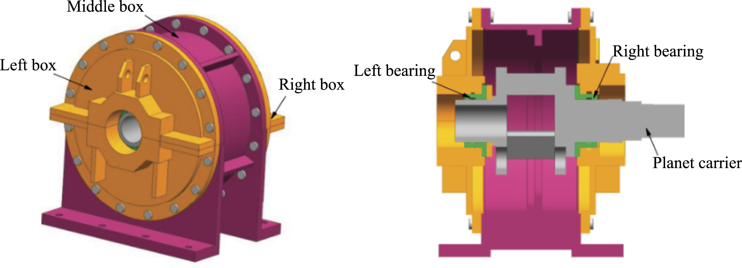
In this paper, the lumped parameter method is used to establish the transfer path dynamics model, as shown in Figure 2. The load on the planet carrier is taken as the excitation source of the system; the middle box as vibration receiving structure; transfer path is mainly by the bearing, bolts, and other connecting elements to transfer the exciting force to the middle box. The model contains six vibrating bodies, namely left box, middle box, right box, left bearing, right bearing, and planet carrier. Dynamic model of transmission path of planet carrier excitation vibration.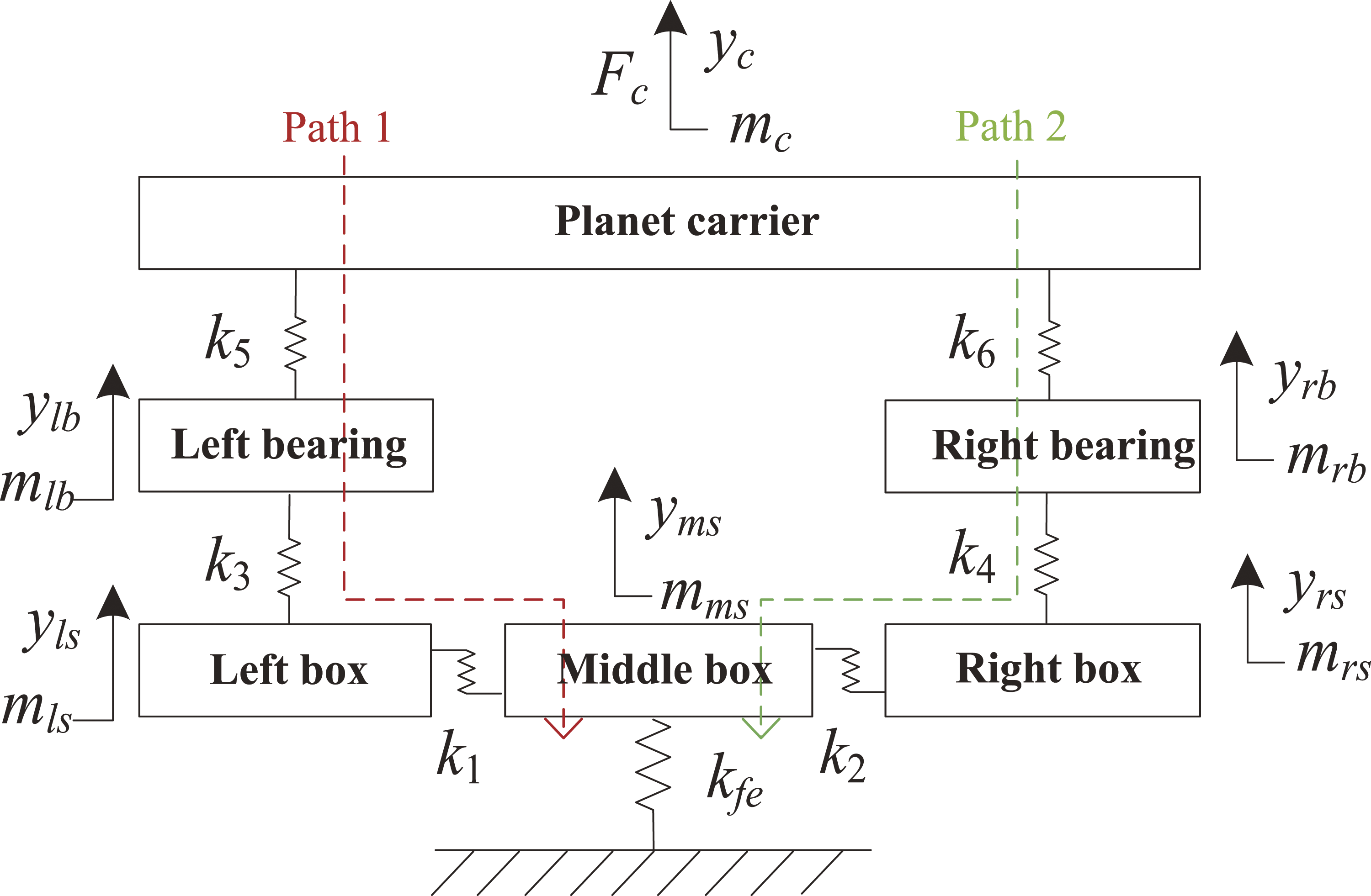
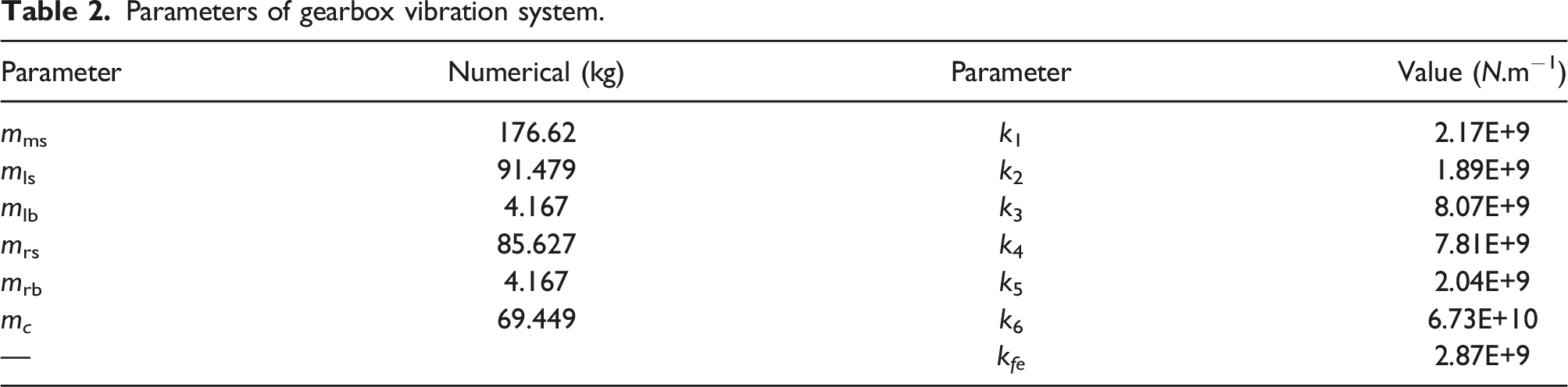
Fc: the excitation force acting on the planet carrier, yls: the vibration displacement of left box, yms: the vibration displacement of middle box, yrs: the vibration displacement of right box, ylb: the vibration displacement of left bearing, yrb: the vibration displacement of right bearing, yc: the vibration displacements of planet carrier under excitation force, mls: the concentrated mass of left box, mms: the concentrated mass of middle box, mrs: the concentrated mass of right box, mlb: the concentrated mass of left bearing, mrb: the concentrated mass of right bearing, mc: the concentrated mass of planet carrier, k1: the shear stiffness of bolt group between left box and middle box, k2: the shear stiffness of bolt group between right box and middle box, k3: the Radial contact stiffness between left bearing and left box, k4: the Radial contact stiffness between the right box and the right bearing, k5: the radial contact stiffness between left bearing and planet carrier, k6: the Radial contact stiffness between right bearing and planet carrier, kfe: the supporting stiffness of the box on the base.
It can be seen from Figure 2 that after the vibration energy generated by planetary gear meshing is transferred to the planetary frame, the vibration energy is transferred to the box through two paths. Therefore, the vibration transmission path from the planetary frame excitation to the middle box is as follows:
Path 1: planetary frame → left bearing → left box → middle box
Path 2: planetary frame → right bearing → right box → middle box
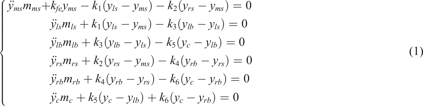
Combined with the transmission path model of reducer box in Figure 2, the dynamic equation of vibration transmission path is obtained by using Newton’s second law
Parameter determination of vibration transmission path model
The contribution of vibration transmission path of planetary reducer box is mainly affected by the radial stiffness between the contact parts and the radial stiffness is determined by the material properties and contact mode of the contact parts, so it is necessary to determine the radial stiffness of each part.
The left box is directly contacted with the middle box along the radial direction. When the left box is vibrated, the vibration is transmitted to the middle box along the contact surface.
Figure 3 is the schematic diagram of the finite element boundary conditions of the left box and the middle box. The contact type of the left box and the middle box end face is No separation, and the other contact is bonded. The middle box is set up with fixed support, and the left box is set up with vertical shear force F, which is 1–5 kN. Because mechanical vibration model only considers single direction vibration, Y direction is set as vibration direction in finite element model. Figure 4 shows the static displacement nephogram of the left box and the middle box under the vertical shear force, from which the average static displacement near the junction of the left box and the middle box can be obtained. The relative difference between them can be expressed as the deformation of the bolt group. Boundary conditions of left and middle box. Static displacement nephogram of left and middle box.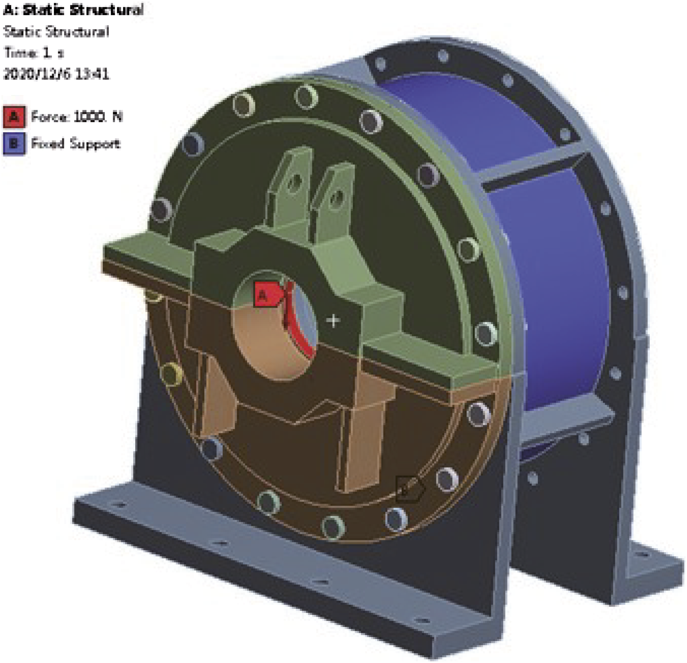
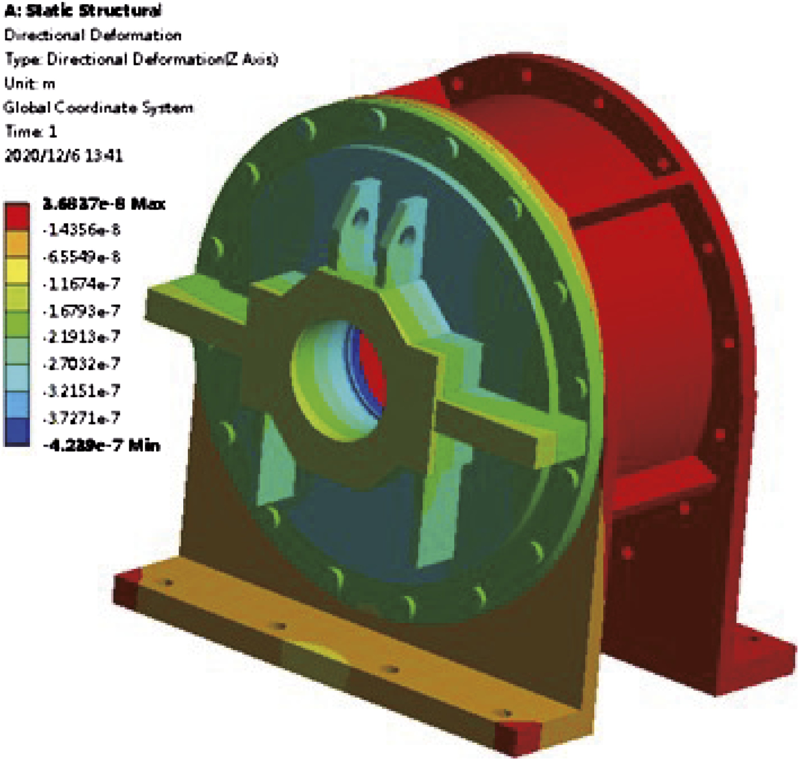
Relative difference.
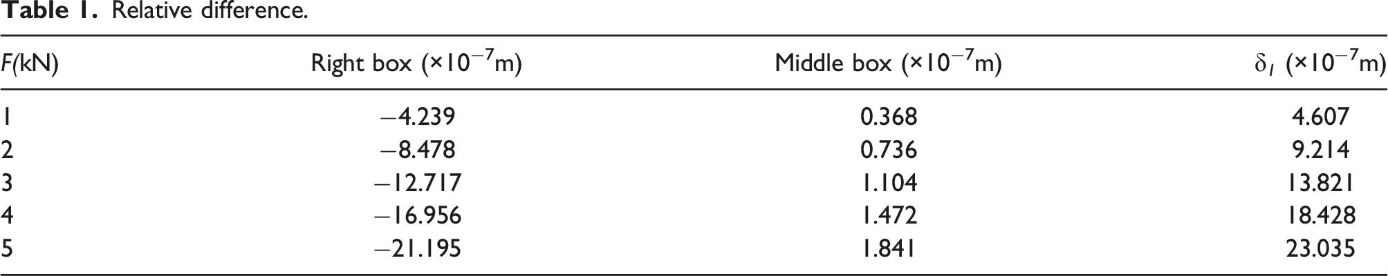
The contact stiffness calculation formula is
The contact stiffness k1 is about 2.621×10⁹ N/m by substituting the data in Table 1 into equation (2).
Parameters of gearbox vibration system.
Analysis of Interventional Loss in Vibration Transmission Path
The vibration system generates vibration under the excitation force and spreads to the entire vibration system along the transmission path. Each transmission path has a positive or negative impact on the vibration response, which is called the contribution of the transmission path to the vibration response. By analyzing the contribution of each transfer path to the vibration response, we can obtain the influence of each transfer path on the vibration response to identify which are the main transfer paths for vibration control.
The intervention loss is used as the evaluation index of path contribution. The interventional loss is defined as the ratio of the load power after a component is connected to the system to the load power before the component is connected to the system, usually in dB, and its expression is
This paper introduces this concept into the vibration transmission path system. When the path separation method is used to analyze the importance of each transmission path, the path involvement loss can be defined as 20 times the common logarithm of the effective value ratio of the receiver response before and after the transmission path connection.
The definition shows that the higher the intervention loss of a path, the greater the weight of the path in the vibration system. It means that this path has greater influence on the vibration transmitted from the excitation source to the base. According to the different responses of the receiver, the intervention loss can be divided into the following categories: displacement intervention loss, velocity intervention loss and acceleration intervention loss. If the acceptor in the vibration transmission path system only has linear motion, the importance of each path can be evaluated by using the velocity intervention loss, so this paper only considers the velocity intervention loss of the receiver.
According to the definition of intervening loss, velocity intervening loss is
First, path 1 of the transfer path model is disconnected, and path 2 is retained. At this time, the system vibration differential equation can be expressed as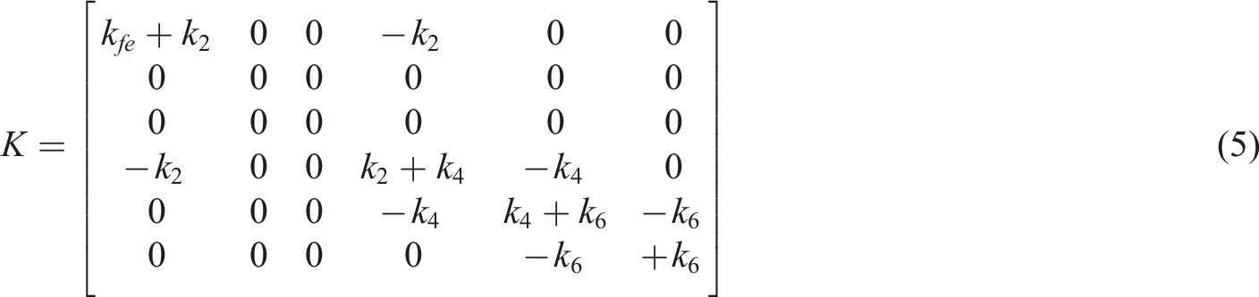
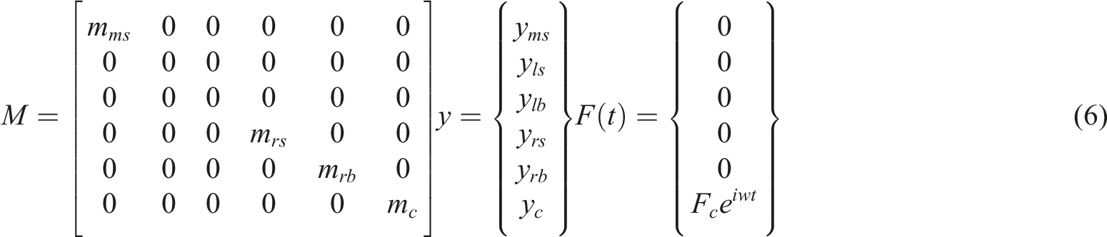
Let the steady-state response be
The speed response is
The velocity intervention loss of path 1 is
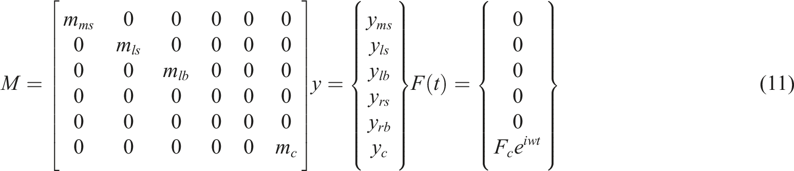
Similarly, path 2 of the transfer path model is disconnected, and only path 1 is retained. At this time, the system vibration differential equation is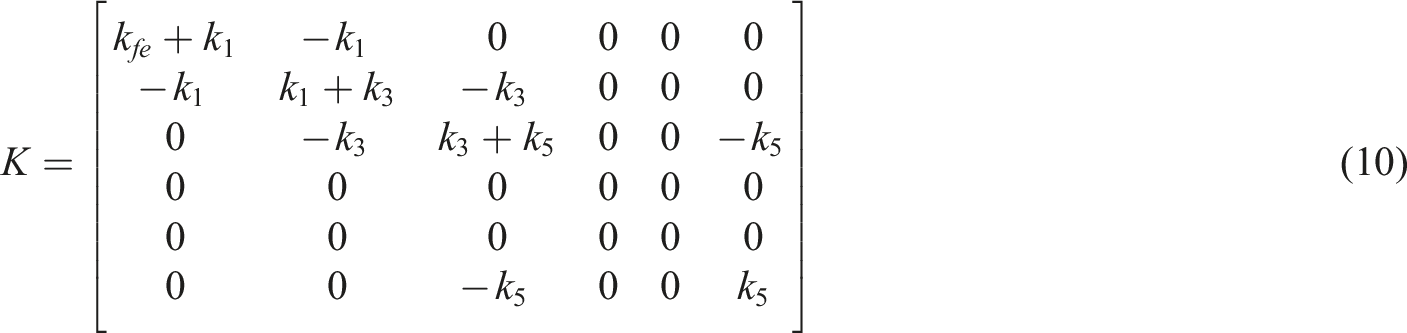
According to equation (9), the interventional loss characteristic curve of path 1 is calculated, as shown in Figure 5, and the interventional loss characteristic curve of path 2 is calculated as shown in Figure 6. Intervention loss characteristic curve of path 1. Interventional loss characteristic curve of path 2.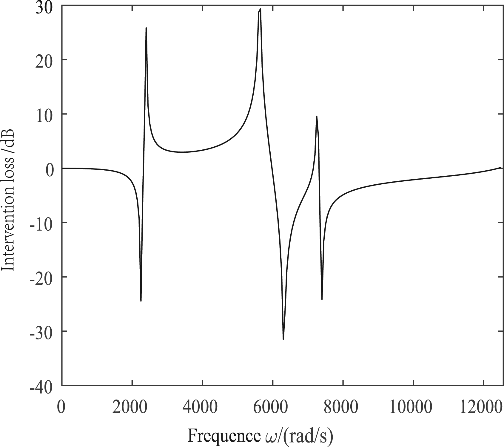
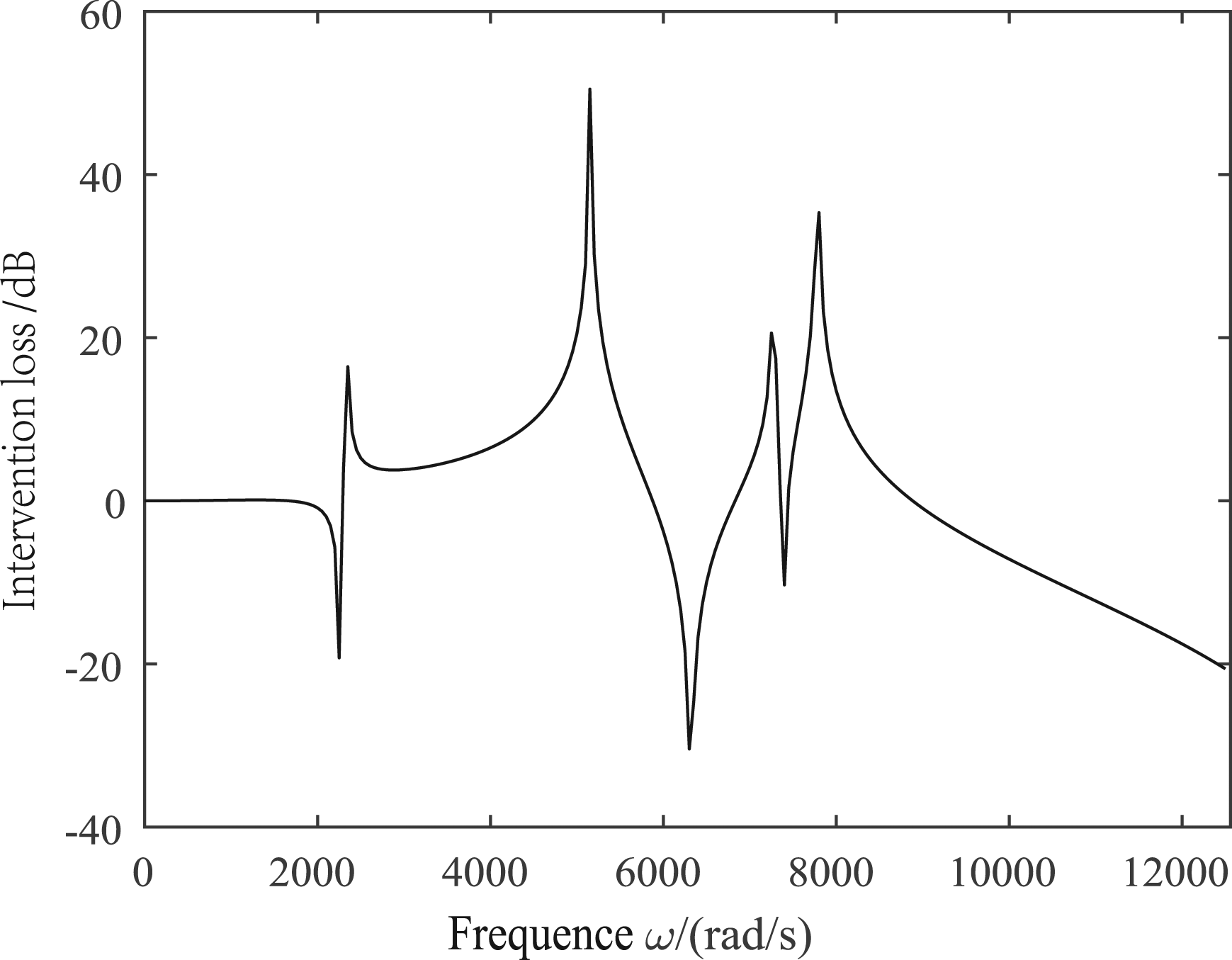
The intervention loss in a certain frequency range is defined as a quantitative evaluation index, namely, evaluation index of intervention loss
ILave1=4.47, ILave2=8.05 are calculated from equation (12). That is, ILave2>ILave1.
Therefore, the contribution of each transmission path is ranked as follows: path 2 > path 1.
Contribution test of vibration transmission path of planetary reducer box
Construction of test platform
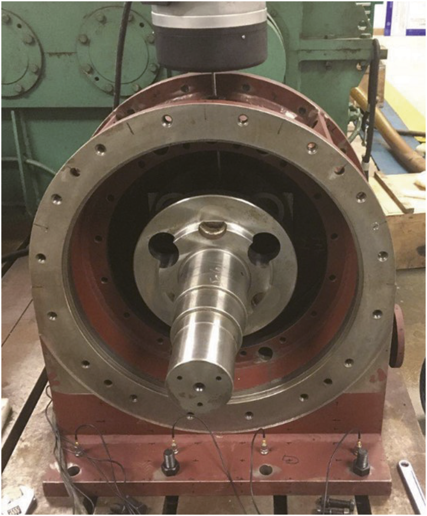
The physical picture of the planetary reducer box is shown in Figure 7. The structure includes the left box, the middle box, the right box, the left sliding bearing, the right sliding bearing, and the planetary frame. The hole is machined above the box in the reducer, and the excitation rod can be extended to excite the planetary frame to simulate the excitation effect of the planetary frame on the box. Planetary reducer box.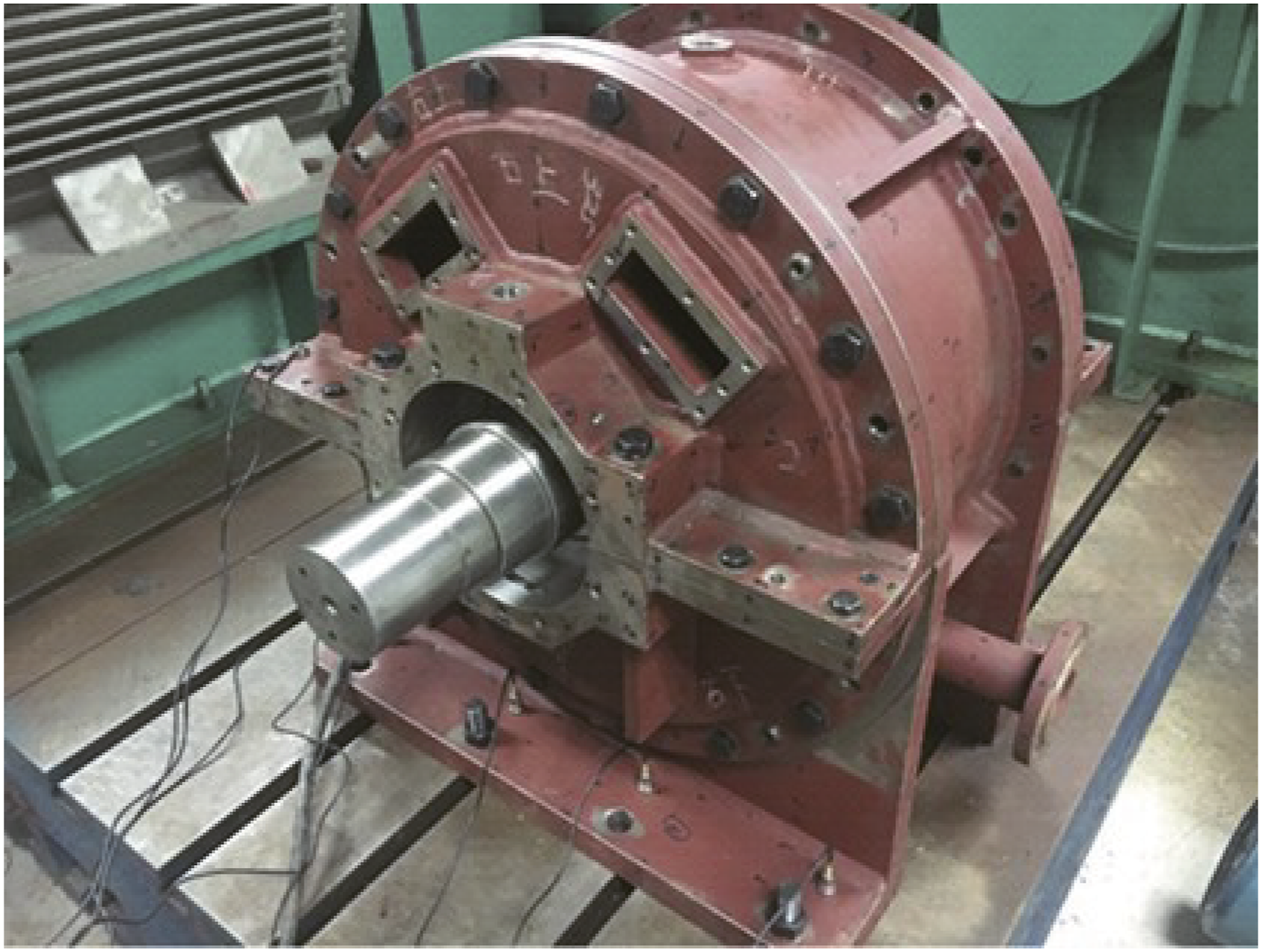
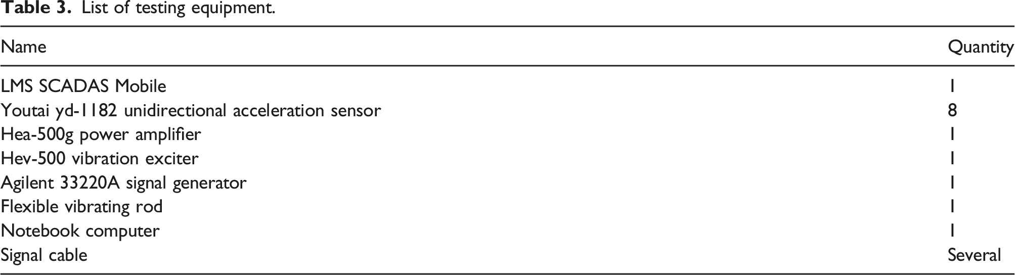
List of testing equipment.
The soft spring suspension method is used to arrange the exciter. The soft spring and the exciter form a single degree-of-freedom vibration system with the natural frequency of ωn= Hardware system of gearbox vibration test. (a) Test hardware, (b) vibration test layout.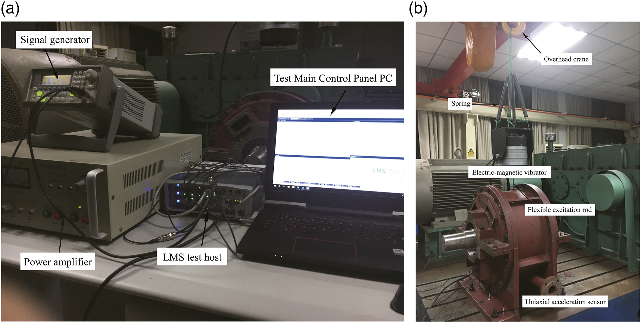
According to the finite element modal analysis, the vibration of the bottom plate near the inner side of the box is large, so eight vibration test points are arranged near the inner side of the eight bolt holes in the bottom plate, as is shown in Figure 9. Position distribution of vibration test points.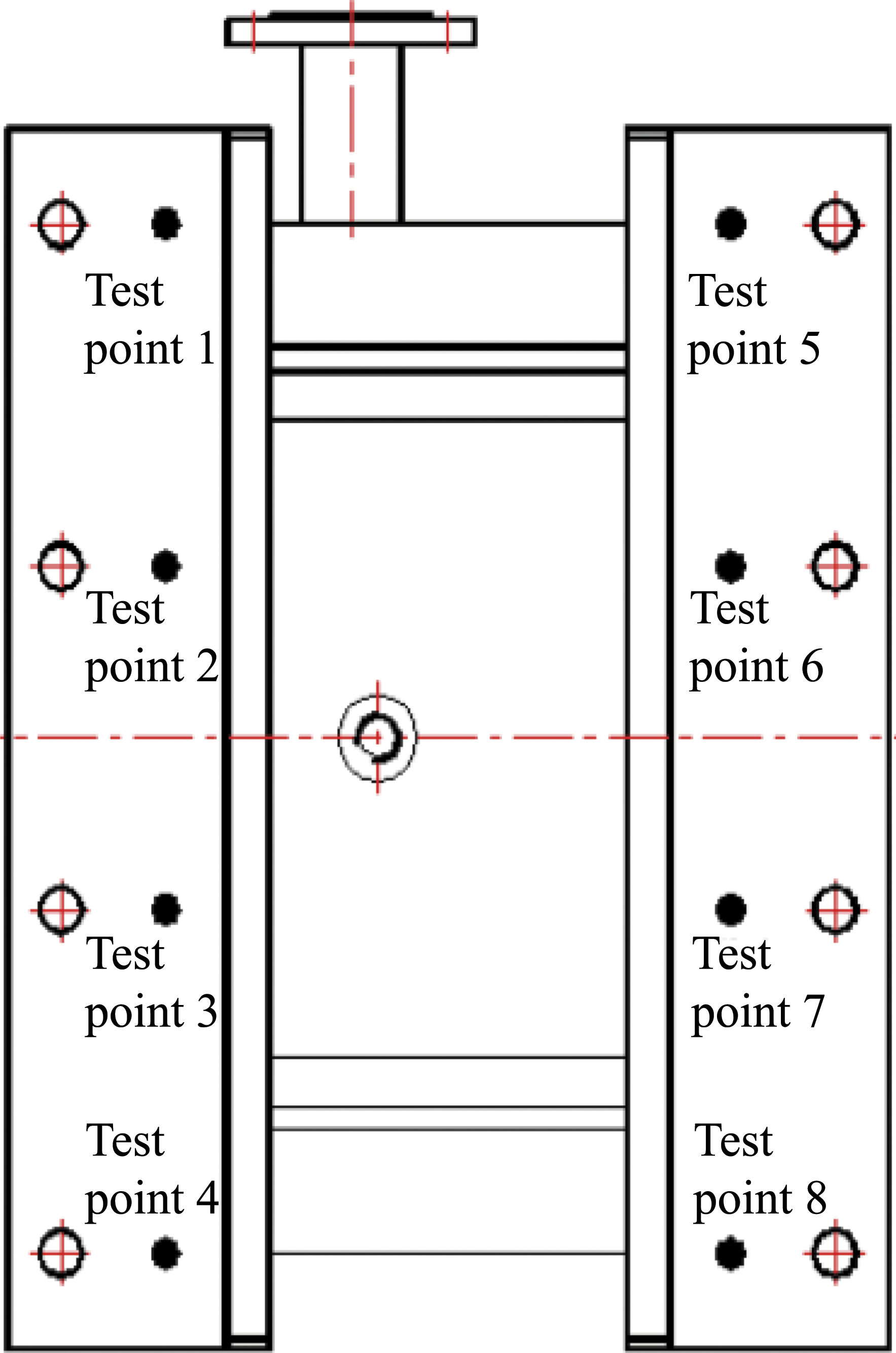
Test steps
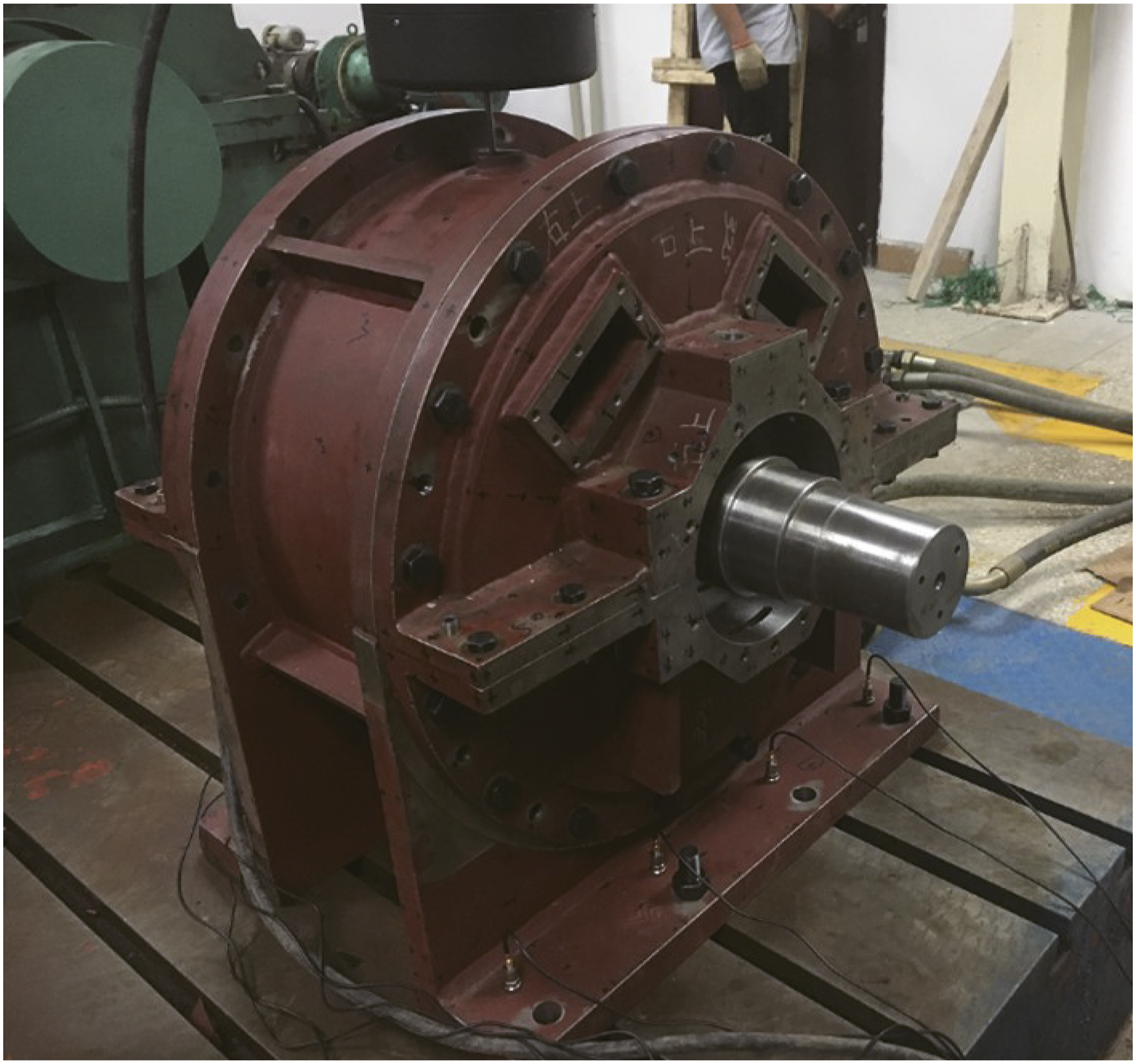
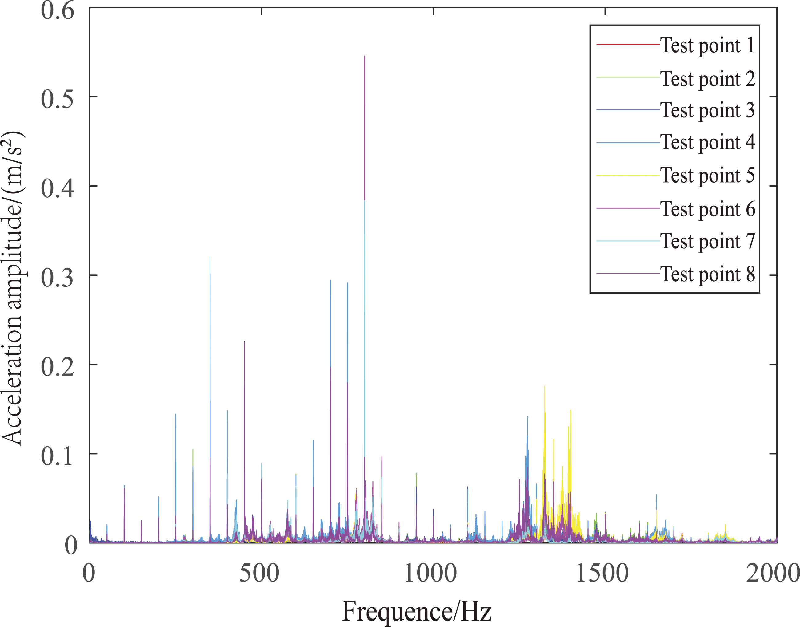
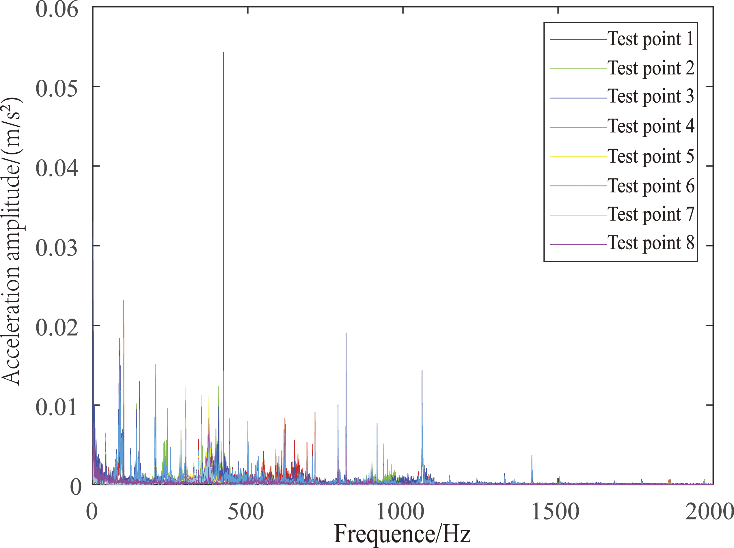
As shown in Figure 10, Figure 11, and Figure 12, conduct vibration test for removing the left box, removing the right box, and keeping the complete box. The flexible rod of the exciter is swept above the planet carrier for frequency excitation. The parameters of the exciter are set in the signal generator, and the frequency range is 5Hz–2000Hz. The vertical acceleration frequency response of eight points was tested. Vibration test diagram of removing left box. Vibration test diagram of removing right box. Vibration test diagram of planetary reducer box.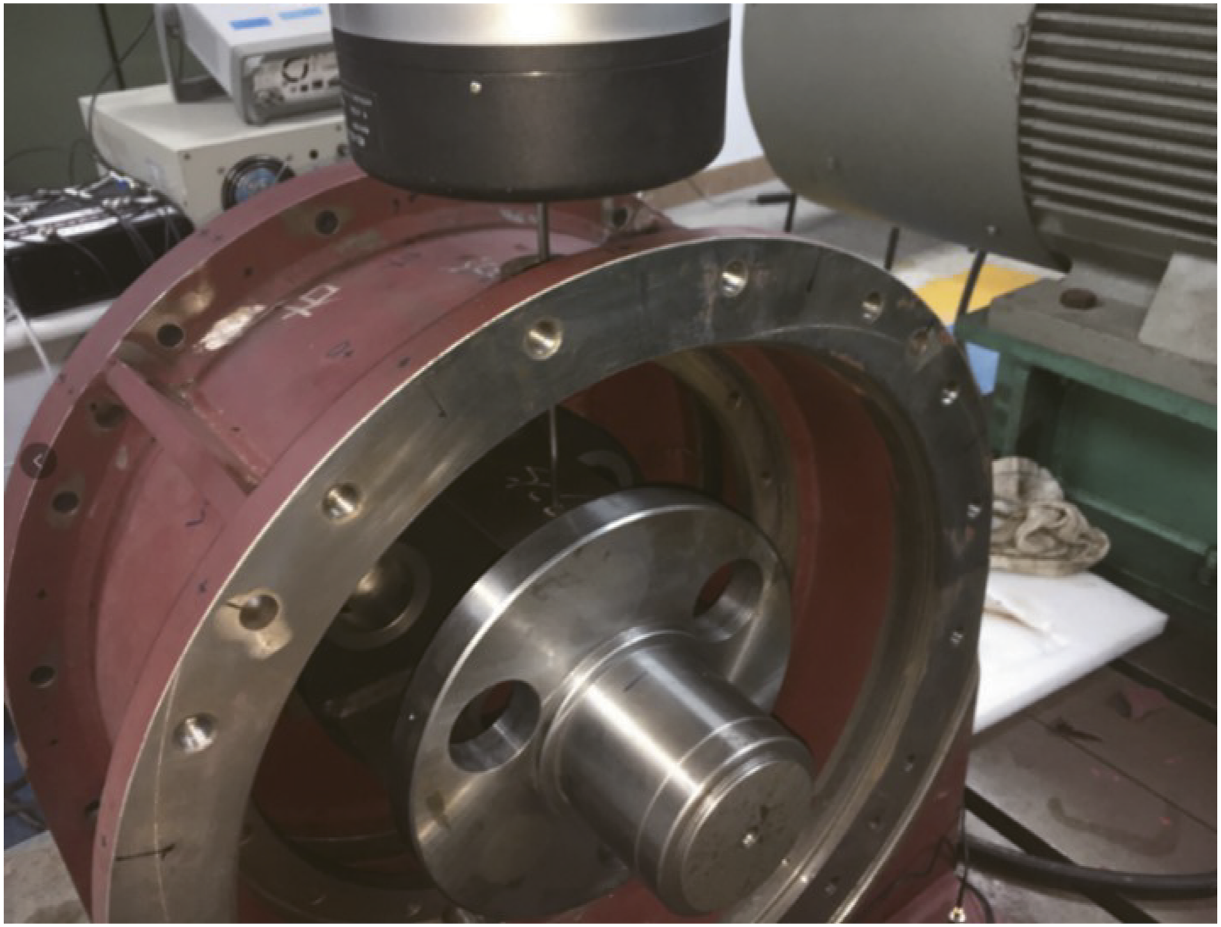
Comparison and analysis of dynamic model calculation and test results
The vibration test results of removing the left box, removing the right box and retaining the whole box are shown in Figure 13, Figure 14, and Figure 15, respectively. Frequency domain response diagram of each test point obtained from the vibration test of the left box removed. Frequency domain response diagram of each test point obtained from the vibration test of the right box removed. Frequency domain response diagram of test points obtained from vibration test of complete planetary reducer box.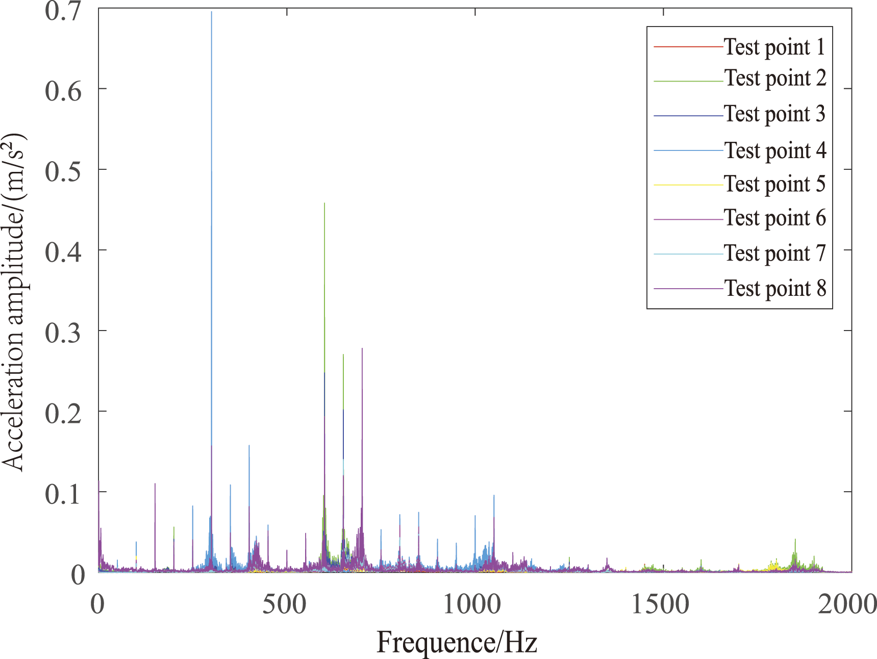
Substituting the frequency domain response of each test point into equation (9), the path intervention loss curve can be obtained. The path involvement loss curve of test point 1 is shown in Figure 16. ILave1=16.73 and ILave2=20.13 are calculated from equation (9). Test point 1 intervention loss curve (a) interventional loss characteristic curve of path 1, (b) intervention loss characteristic curve of path 2.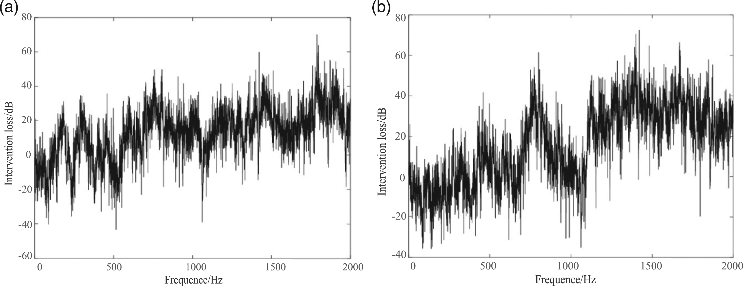
Evaluation index of path involvement loss of each test point.
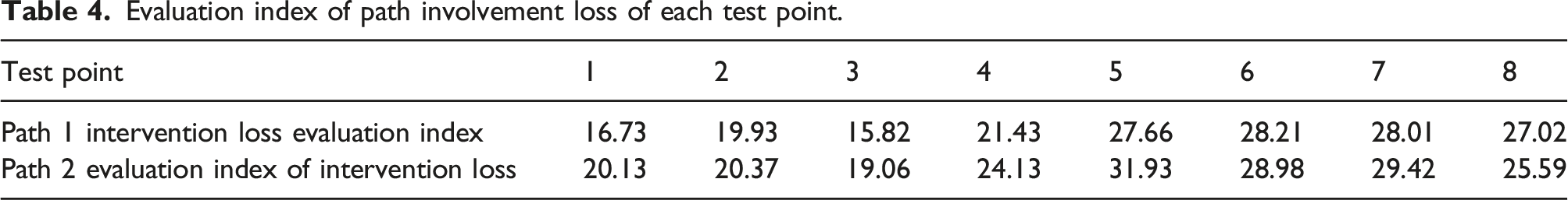
It can be seen from Table 2 that except for assessment point 8, the intervention loss of path 2 of other test points is greater than that of path 1, so the test results of test point 8 can be regarded as test errors. Therefore, from the analysis of a single test point, the intervention loss evaluation index of path 2 is larger, indicating that the vibration contribution of path 2 is greater than that of path 1.
In order to evaluate the importance of each path as a whole, the average values of the intervention loss evaluation indexes of all the test points corresponding to each path are compared. The average value of the intervention loss evaluation index of path 1 is 23.06, and the average value of the intervention loss evaluation index of path 2 is 24.95. Then, the intervention loss evaluation index of path 1 accounts for 48%, and the intervention loss evaluation index of path 2 accounts for 52%.
Comparison of calculation results of dynamic model and test results.
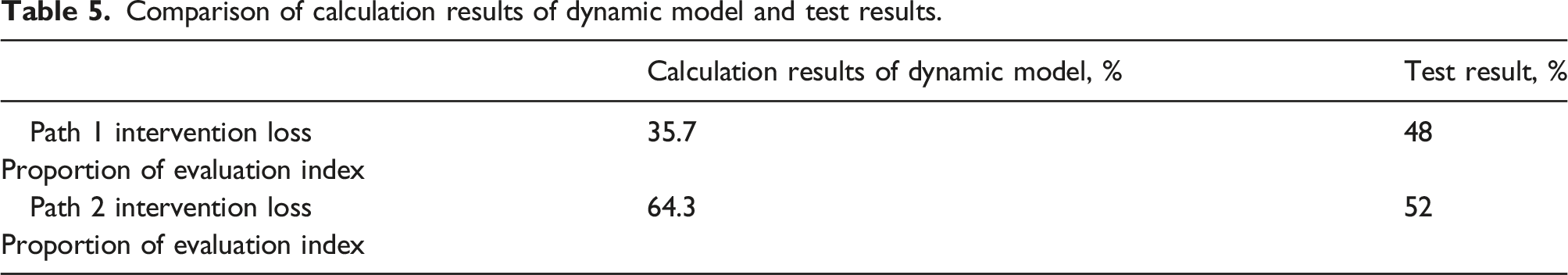
When the intervention loss of each path is evaluated as a whole, path 2 is greater than path 1. It shows that for the vibration response at the foot of the planetary reducer box, the contribution of path 2 is greater than that of path 1, which is consistent with the calculation results of the transmission path dynamic model.
Conclusions
The contribution of transmission path to planetary reducer box is studied from the perspective of velocity intervention loss. The research conclusions are as follows: (1) The dynamic model of the vibration transmission path of the planetary reducer box is established by using the transmission path analysis method, and the motion differential equation of the vibration system is established by using the generalized coordinates. Based on the vibration test experiment, the dynamic model of the transmission path is verified for the vibration response at the foot of the reducer box. The theoretical results are consistent with the experimental results, indicating that the dynamic model of the vibration transmission path can well reveal the vibration transmission law of the reducer box. (2) According to the velocity intervention loss analysis, the main vibration transmission path of the box is found. For the planetary reducer box studied in this paper, when the planet carrier is the excitation and the middle box is the final receptor of vibration, the contribution of path 2 is the largest. This shows that the right bearing plays a major role in vibration transmission, and this path can be used as the preferred path for vibration and noise reduction.
Footnotes
Declaration of conflicting interests
The author(s) declared no potential conflicts of interest with respect to the research, authorship, and/or publication of this article.
Funding
The author(s) disclosed receipt of the following financial support for the research, authorship, and/or publication of this article: This work was supported by the National Key Laboratory of Science and Technology on Helicopter Transmission (Grant No. HTL-A-22G05).