
Abstract
This paper aimed to systematically maximize hydraulic efficiency and pump head for mine drainage pump using numerical simulation method and optimization design method. First, the preliminary design of the pump is carried out according to the traditional design method, and then the impeller and diffuser of mine drainage pump are optimized by orthogonal test method and computational fluid dynamics numerical simulation method aiming at the hydraulic efficiency of the pump. The results show that under the rated working conditions, the hydraulic efficiency of the optimized mine drainage pump is 82.11%, the pump head is 25.94 m, and the hydraulic efficiency and pump head are increased by 3.58% and 1.53 m, respectively. Furthermore, under the flow conditions of 0.8Qd, 1.0Qd and 1.2Qd, the average radial force of the optimized impeller is reduced by 22.4 N, 18.5 N and 13.1 N respectively, and the average axial force is reduced by 36.7 N, 30.2 N and 27.3 N compared with the original scheme. It indicated that the optimization effect of mine drainage pump is obvious. Through the analysis of the characteristics of the internal flow field, it is illustrated that the reasonable control of the internal flow law of the pump can effectively improve the hydraulic performance of the pump and improve the stability of the pump operation.
Introduction
With the development of science and technology, the application field of pump is expanding rapidly, which plays an important role in the fields of petroleum, national defense, aerospace and water conservancy engineering. 1 In recent years, centrifugal pump has developed in the direction of high efficiency, large flow and high performance, and has become a widely used general machinery in the field of drainage rescue and disaster relief. According to statistics, mining drainage equipment consumes a lot of energy, and the performance of water pumps greatly affects the economic benefits of the department. 2 Therefore, in order to save energy and reduce emissions, build a conservation-oriented society and improve the national economy, it is very necessary to improve the performance of centrifugal pump.3,4
Centrifugal pump is mainly designed by velocity coefficient method, flow field analysis method, loss extreme value method, criterion screening method and similarity conversion method for hydraulic design and model conversion.5-7 At the same time, numerical simulation is used to predict pump performance and shorten development cycle. Stepanoff 8 analyzed the structure and performance parameters of multiple pumps, counted the relationship between the specific speed and each parameter, and put forward the Stepanoff speed coefficient diagram. Sano et al. 9 studied the fluid velocity distribution in the guide vane of the centrifugal pump, and pointed out that the velocity in the middle passage of the guide vane has the characteristic of periodic variation, and that the pressure in the guide vane has a gradient distribution along the radial direction. Xie et al. 10 used the multi-parameter optimization method to design the impeller profile and found that the blade profile can effectively improve the internal flow field of the impeller. J H Kim et al. 11 analyzed the influence of the geometric parameters of the optimized pump on the performance of the impeller by using CFD and response surface method. Kim et al. 12 studied the performance characteristics of the centrifugal pump impeller by using the experimental design method (DOE), and found that the impact angle and blade outlet angle are the most important parameters affecting the pump performance. Duccio et al. 13 adopted the inverse problem design method to design the guide vane of the jet pump, made a hydraulic analysis of the design scheme, and pointed out the characteristics of pressure distribution and internal flow distribution in the guide vane.
In addition, a large number of variables are involved in the optimization design of the centrifugal pump, and the random combination of these variables can have different effects on the performance of the pump. Therefore, determining the optimal combination of variables is the key to the optimization process. 14 For a long time, a variety of optimization methods have been widely used in rotodynamic pump design,15-20 which improves the designers' methods of pump optimization design. At present, the orthogonal test method has been widely used in pump design, and its advantage is that it can reduce the test times and shorten the test cycle through a reasonable test scheme, and find out the optimization scheme more quickly.21-23 Yuan et al. 24 through the orthogonal test method, the main geometric parameters of the impeller and diffuser of the high specific speed axial flow pump are optimized, and the efficiency of the pump is improved. Li et al. 25 used the orthogonal test method to optimize the design of the blade inlet and outlet angles, wrap angle and outer diameter of the high-head diffuser mixed flow pump impeller, which improved the head and efficiency of the high-head diffuser mixed flow pump. Zheng et al. 26 studied the application of multi-objective optimization of axial flow pump by orthogonal experiment, and found the main geometric parameters that affect the performance of axial flow pump.
In order to improve energy efficiency and obtain greater economic benefits. In this paper, the preliminary design of the pump is carried out according to the traditional design method, and then the impeller and diffuser of mine drainage pump are optimized by orthogonal test method and CFD numerical simulation method. By improving the geometric parameters of the impeller and blade, the internal flow law of the pump is effectively controlled, thus the fluid flow loss is reduced, and the hydraulic performance of the pump is improved. Through the comparison of the test results, the reliability of the optimization method is verified. Finally, through the analysis of the characteristics of the internal flow field, the reasons for improving the hydraulic performance of the pump are analyzed.
Hydraulic design of mine drainage pump
The target design parameters of high efficiency and large flow mine drainage pump are as follows: the rotation speed is 1450 r/min, the head is 25m, the flow rate is 100m3/h, and the efficiency is 82%. In this paper, a mine drainage centrifugal pump is designed by using the velocity coefficient method.
27
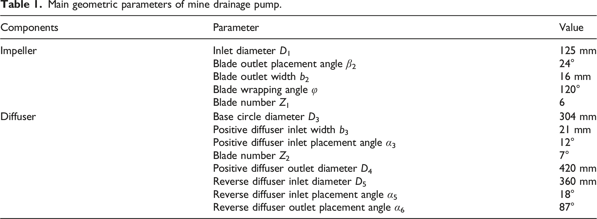
The pump model is shown in Figure 1, and its main geometric parameters are presented in Table 1. Manufactured model of mine drainage pump. (a) Impeller, (b) Diffuser, (c) Model pump. Main geometric parameters of mine drainage pump.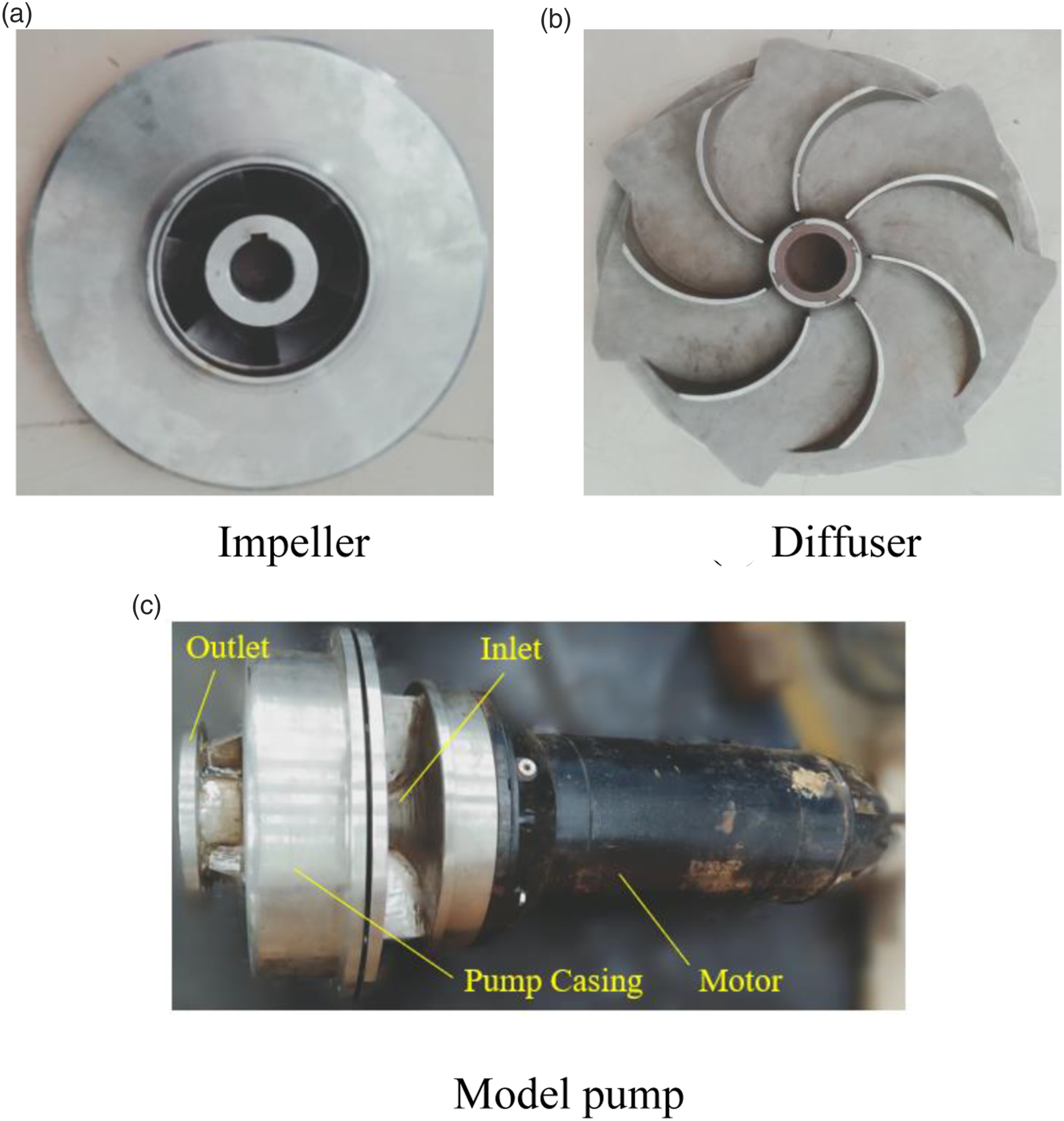
As shown in Figure 2, it is the calculation domain model of mine drainage pump, which includes intake section, impeller, positive diffuser, reverse diffuser and outlet extension section. For the full development of fluid flow, it is necessary to extend the outlet of the model appropriately. Water body shape of mine drainage pump.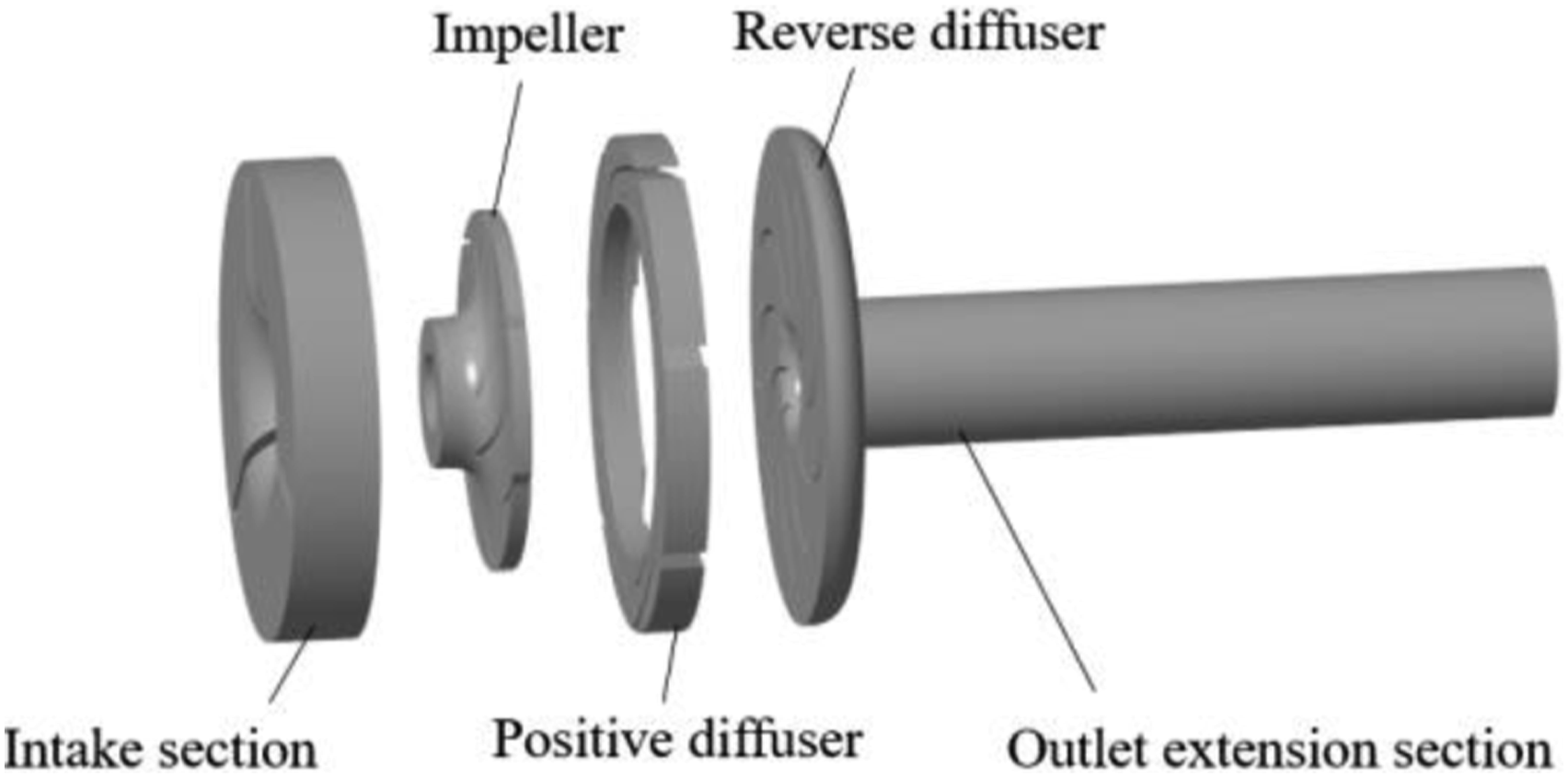
Numerical simulation
Creation of meshing
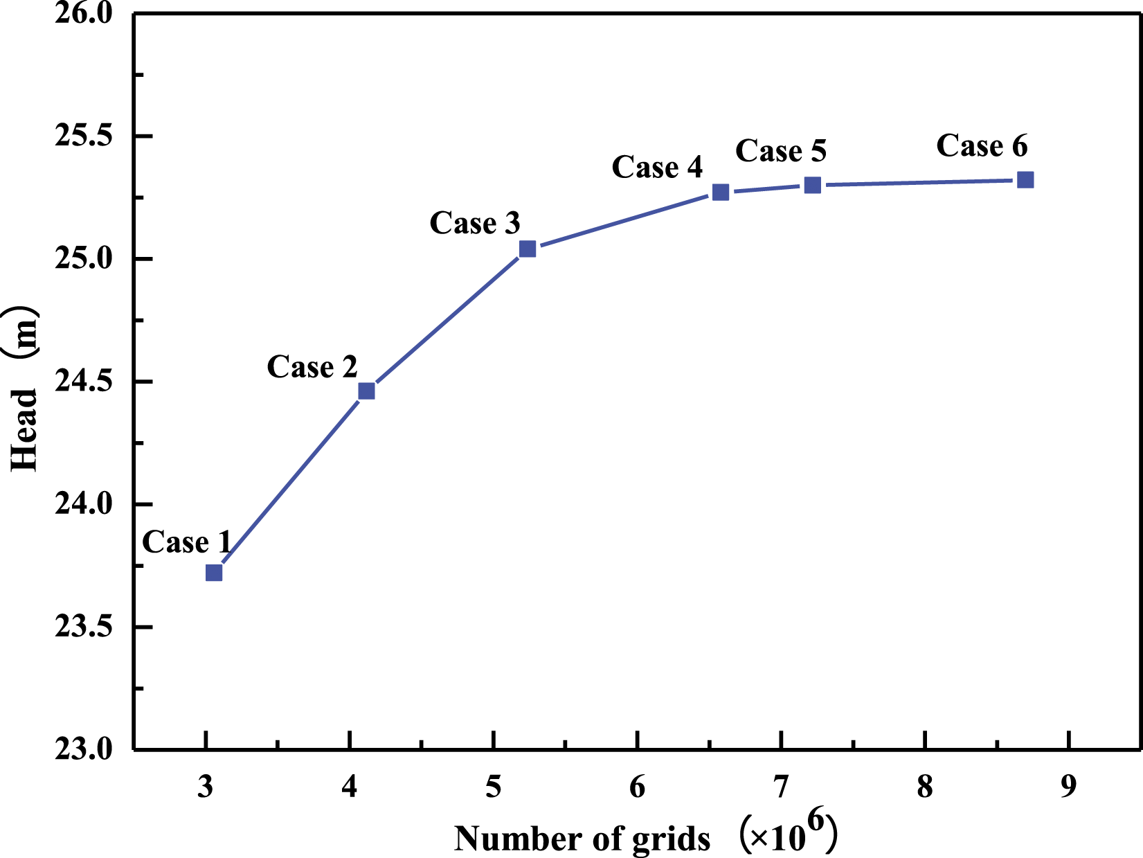
The unstructured mesh with strong geometric adaptability is selected to divide the calculation domain of mine drainage pump. A fine mesh is required for turbulence model of renormalization group (RNG) k-ε, so mesh refinement is carried out in the region near the wall, and the height of the first layer grid is adjusted to control the wall y+ value near 50. The mesh of components is illustrated in Figure 3. Taking into account the influence of computing resources and calculation accuracy, the model grids of six schemes are divided to verify the irrelevance, and the pump head prediction value of each scheme grid is shown in Figure 4. In this paper, the grid size of impeller and diffuser is adjusted to form the different grid schemes. Comparing the predicted pump head values of Case 4 and Case 6, it is found that the calculation error is less than 1%, and finally the grid number of Case 4 is selected for simulation analysis. Model mesh diagram. (a) Impeller (b) Positive diffuser (c) Reverse diffuser. Grid irrelevance analysis.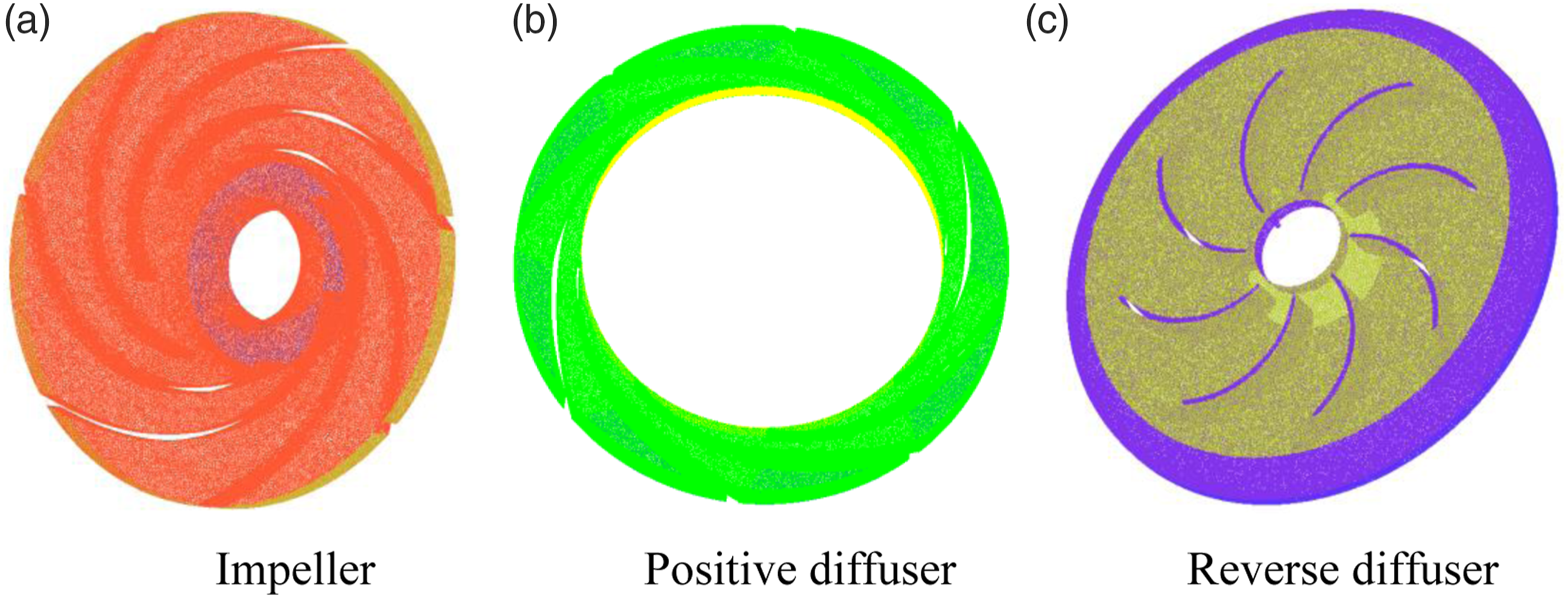
Definition of the physics of the model
Domain and interface
The model includes five calculation regions: pump inlet, impeller, positive diffuser, reverse diffuser and pump outlet pipe, and the simulation were performed under steady and transient state conditions. The calculation regions defined constant temperature water with the density of 997 kg/m3 and the viscosity of 8.899 × 10⁻⁴ kg/m
Given the movement of the impeller blades relative to the diffuser and stationary pipe, the analysis involved multiple frames of reference. A rotating reference frame is imposed for the impeller domain, while the inlet, diffuser and outlet pipe are established in a stationary reference frame, and the grids between the calculation domains are associated with general grid interface (GGI). The static and dynamic components exchange data at the interface. In the steady calculation, in order to eliminate the influence of the rotating reference frame on the calculation, the frozen rotor was established at the interface between the intake section and the impeller, and between the impeller and the positive diffuser. The transient rotor stator interface was established in transient calculation.
Boundary conditions
It was pretty important to establish boundary conditions that accurately reflected the actual situation in pump simulation. For better convergence and robustness of the results, the total pressure was established at the inlet of the pump with a turbulent intensity of 5% and mass flow at the outlet of the pump outlet pipe. Simultaneously, no-slip conditions were imposed on the walls and the impeller blades, as well as wall conditions on the diffuser.
Turbulence and treatment near walls
The turbulence model RNG k-ε, which makes corrections of the coefficients in the equation of the standard turbulence model k-ε, and can better predict the rotational flow. 28 The turbulence model RNG k-ε was used to simulate the three-dimensional incompressible viscous turbulent flow inside the mine drainage pump. Likewise, the Scalable wall function is selected to calculate the near-wall region, which can improve the calculation results of the near-wall area.
Calculation method and result acquisition
The appropriate calculation method is helpful to the convergence. The governing equations are discretized by a second-order upwind scheme in space, and the convection term is discretized by the commonly used central-difference scheme. The convergence accuracy of the root mean square RMS was set to 10−4. In the unsteady calculation, the steady calculation result was used as the initial condition, the calculation step is the time of the impeller rotating 1°, a total of six circles are calculated, and the calculation result of the last circle was selected for the unsteady characteristic analysis.
Data analysis
In experiments and numerical calculations of pump, the main parameters are head and efficiency, which are defined as follows


Hydraulic performance comparison
In order to evaluate the hydraulic performance of the mine drainage pump and verify the applicability and accuracy of the numerical simulation method, the open water pump test bench of the Research Center of Fluid Machinery Engineering and Technology of Jiangsu University was used to perform the performance test. The test system is shown in Figure 5 In the test, the data of outlet pressure, outlet flow, motor speed, system voltage and current of mine drainage pump were collected. The selected instrument parameters are shown in Table 2. Schematic diagram of performance evaluation test bench. Instrument parameters.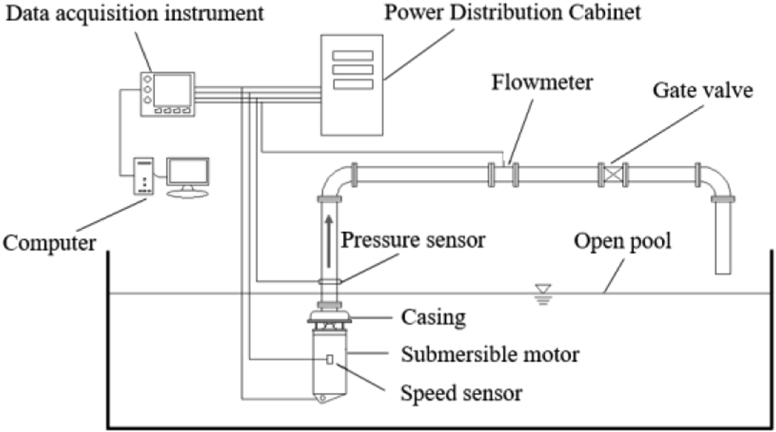
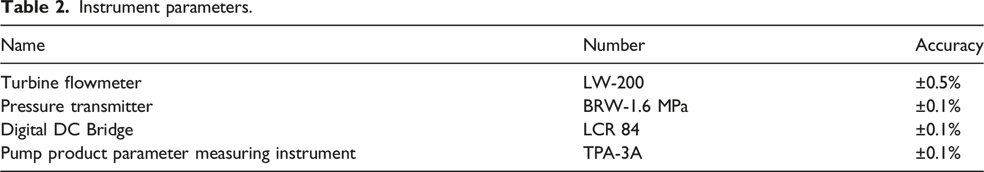
Figure 6 shows the comparison of hydraulic performance test results and numerical simulation results of mine drainage pump. The test efficiency value of the mine drainage pump under rated conditions is 78.53%, and the CFD simulation efficiency value is 79.62%. Compared with the design target hydraulic efficiency value of 82%, the mine drainage pump did not reach the target. Therefore, it is necessary to optimize the hydraulic efficiency of the mine drainage pump. In addition, Figure 6 shows that the change trend of the experimental test result curve and the numerical simulation result curve has a good consistency, and the error of the pump head and efficiency value under each working condition is less than 5%. The numerical simulation error satisfies the actual engineering requirements, indicating that the numerical simulation method is acceptable. Comparison of hydraulic performance on mine drainage pump.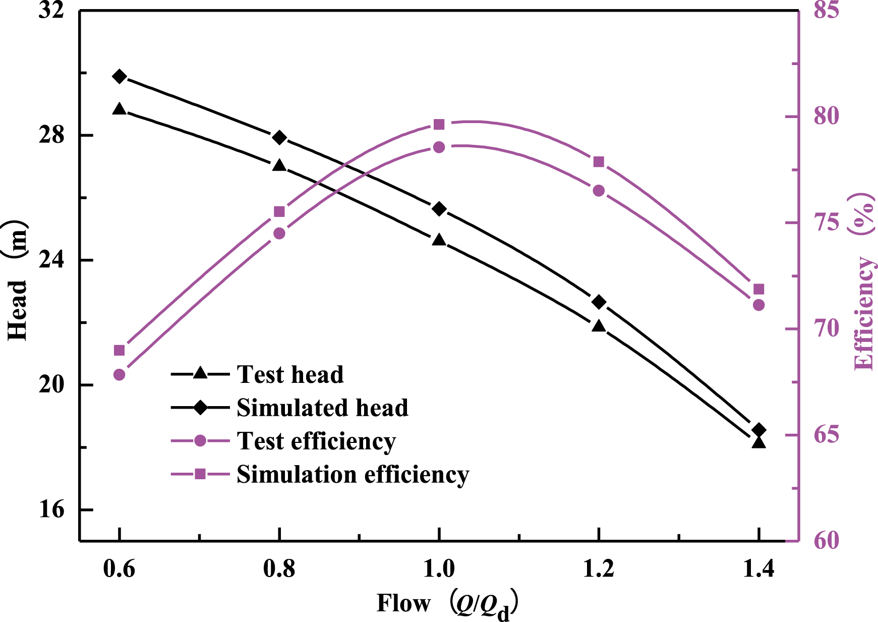
Optimization of overcurrent components
Impeller optimization
Orthogonal test table of impeller.
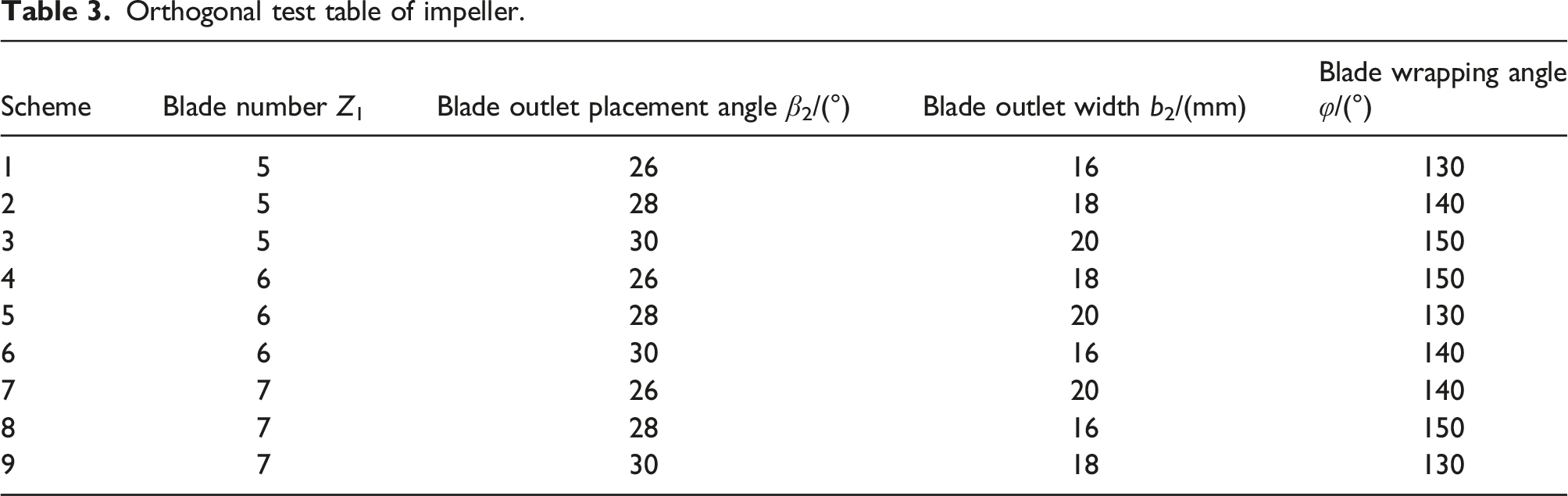
Numerical calculation is carried out under the condition of design flow Qd=100 m3/h, and the efficiency and pump head of pump operation are taken as evaluation indicators. The calculation results under nine groups of test schemes are shown in Figure 7. Numerical simulation results.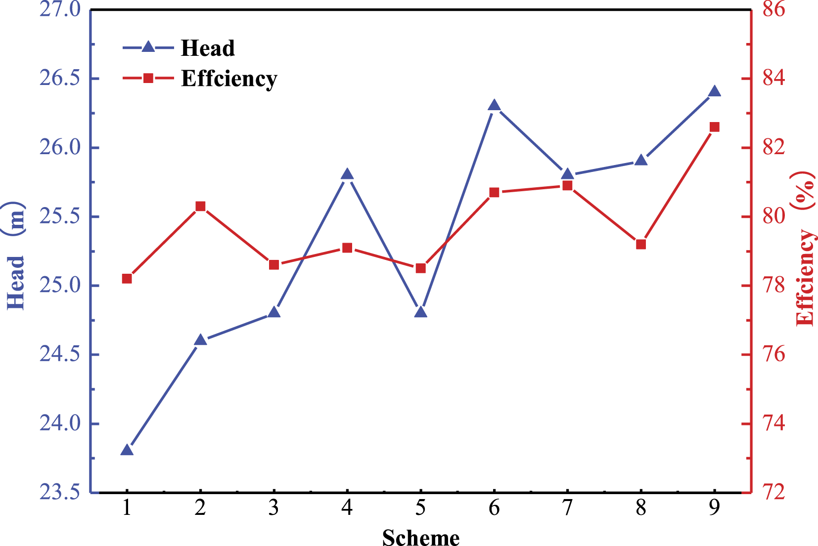
Range analysis of efficiency and pump head.
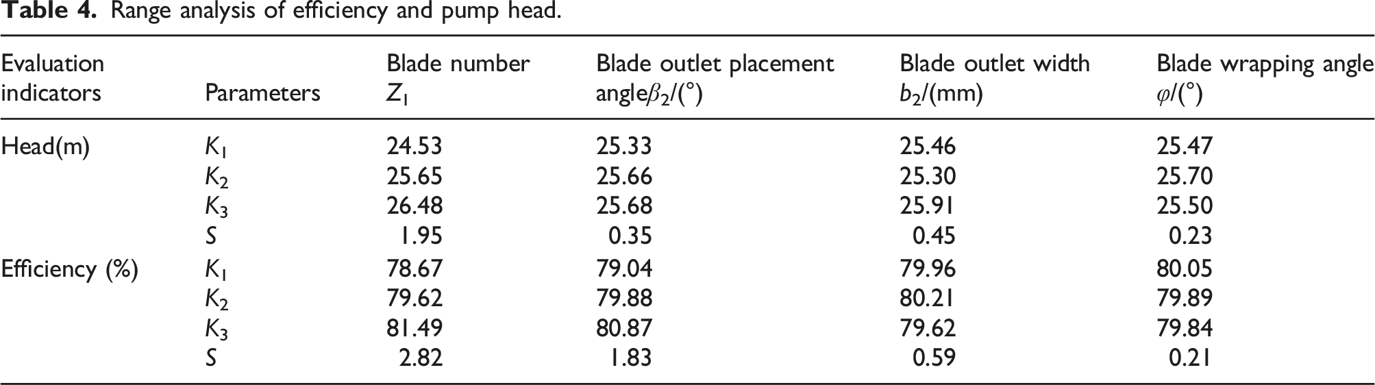
As can be seen from Table 4, the primary and secondary order of the effects of various factors on the efficiency is as follows: Z>β2>b2>φ, the primary and secondary order of the influence of various factors on the pump head is as follows: Z>b2>β2>φ.
Comparing the Ki(i=1, 2, 3) values of the various factors, to improve the efficiency of the mine drainage pump and at the same time increase the pump head, the optimal combination scheme adopted is: Z=7, β2=30°, b2=18 mm, φ=130°.
Diffuser optimization
Geometric parameters of the diffuser optimization scheme.
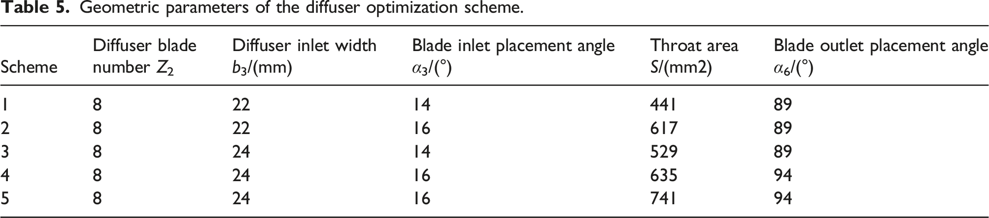
Figure 8 is an expanded view of the speed at a single inlet flow channel of the diffuser under rated conditions on different schemes. It can be seen from the figure that due to the impact of the impeller’s outflow fluid on the positive diffuser blades, there is a large velocity gradient at the leading edge of the diffuser inlet. The velocity gradient at the inlet channel of scheme 1, scheme 2 and scheme 3 is larger than that under scheme 4 and scheme 5. The small inlet width and angle of the diffuser under these three schemes enhances the mutual displacement and impact effects of fluids. Compared with the other three schemes, the range of high-speed zone of fluid in scheme 4 and 5 is smaller, and the velocity distribution of fluid entering the diffuser is more uniform. Velocity distribution at the inlet of the diffuser channel under rated condition. (a) Scheme 1 (b) Scheme 2 (c) Scheme 3 (d) Scheme 4 (e) Scheme 5.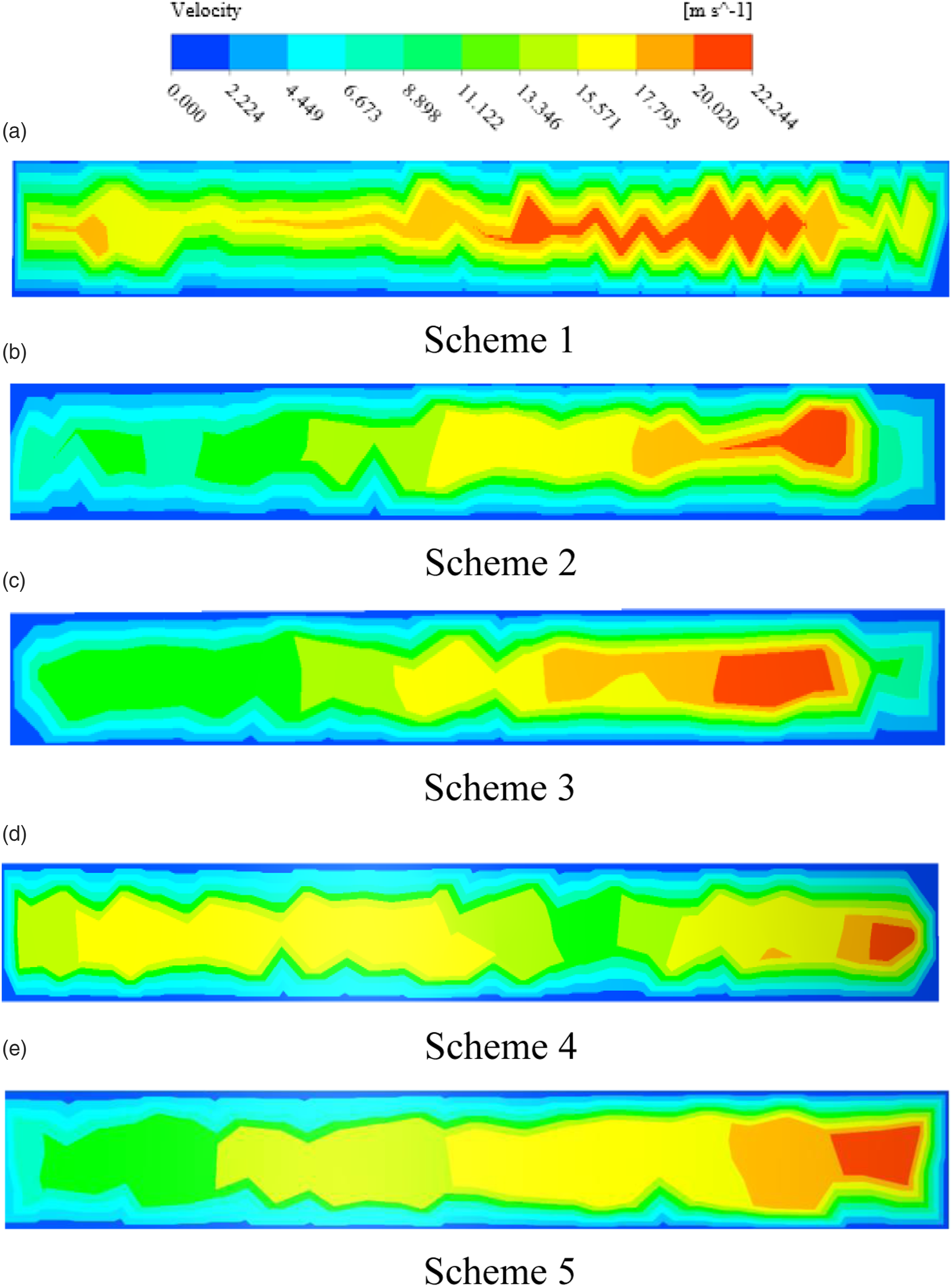
Figure 9 shows the velocity distribution of the diffuser for each scheme under rated condition. It can be seen from the figure that scheme 1, scheme 2 and scheme 3 form a large area of low-velocity vortex area on the wall of the diffusion section. This is because the throat area of the three schemes is small, and the fluid is squeezed when flowing into the diffusion section and form a relative blocking effect. With the increase of the throat area and the blade inlet placement angle, the streamline distribution in the diffusion section becomes uniform, the fluid vortex in Scheme 4 has basically disappeared, and the streamline distribution becomes more regular. The streamline distribution of Scheme 5 is similar to Scheme 4. Due to the increase of its throat area, the velocity of the fluid at the outlet of the positive diffuser decreases. However, the decrease of the velocity at the trailing edge of the outlet section of the positive diffuser will lead to the slip phenomenon when the fluid flows into the transition section, and then increase the hydraulic loss. velocity streamline diagram of diffuser under rated condition. (a) Scheme 1 (b) Scheme 2 (c) Scheme 3 (d) Scheme 4 (e) Scheme 5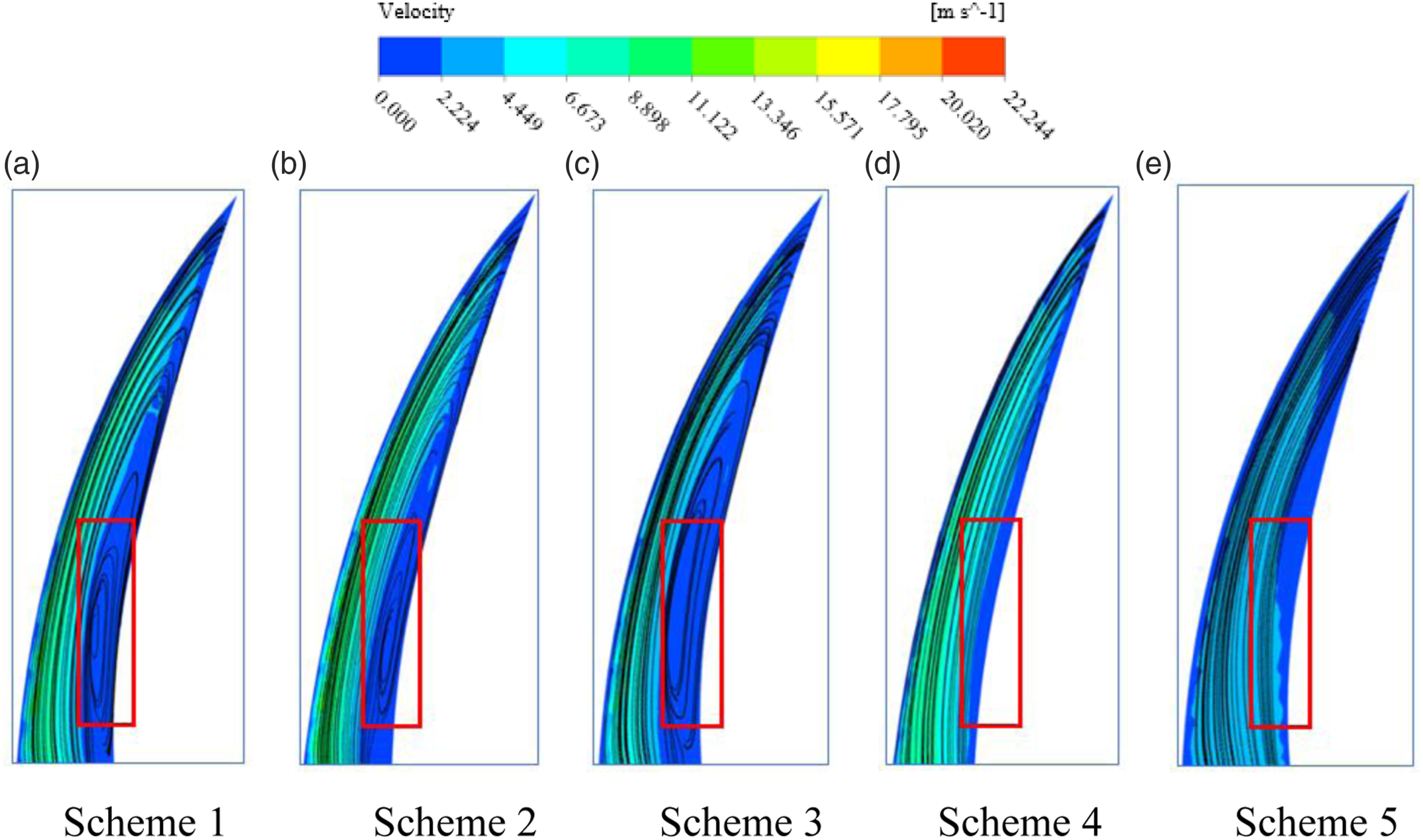
Figure 10 shows the hydraulic losses of diffuser at 0.8Qd, 1.0Qd and 1.2Qd. It can be seen that the maximum difference of the hydraulic loss in the diffuser under different schemes can reach 3.2 m, the hydraulic loss in the diffuser in scheme 1 is the largest, and the loss in the diffuser in scheme 4 is the smallest. Under the rated condition, compared with scheme 1, the hydraulic loss in the diffuser of scheme 2 and scheme 3 is reduced by about 1.2 m and 0.7 m, the average hydraulic loss in the diffuser of scheme 4 is about 4.2 m, which is about 1.8 m less than that of scheme 1, and the hydraulic loss in the diffuser of scheme 5 is about 0.2 m higher than that of scheme 4. Comparing the parameters of the various diffuser schemes, it can be found that the throat area has a greater impact on the hydraulic loss in the diffuser, and the hydraulic loss in the diffuser can be reduced by appropriately increasing the diffuser throat area. Hydraulic loss of diffuser. (a) Scheme 1 (b) Scheme 2 (c) Scheme 3 (d) Scheme 4 (e) Scheme 5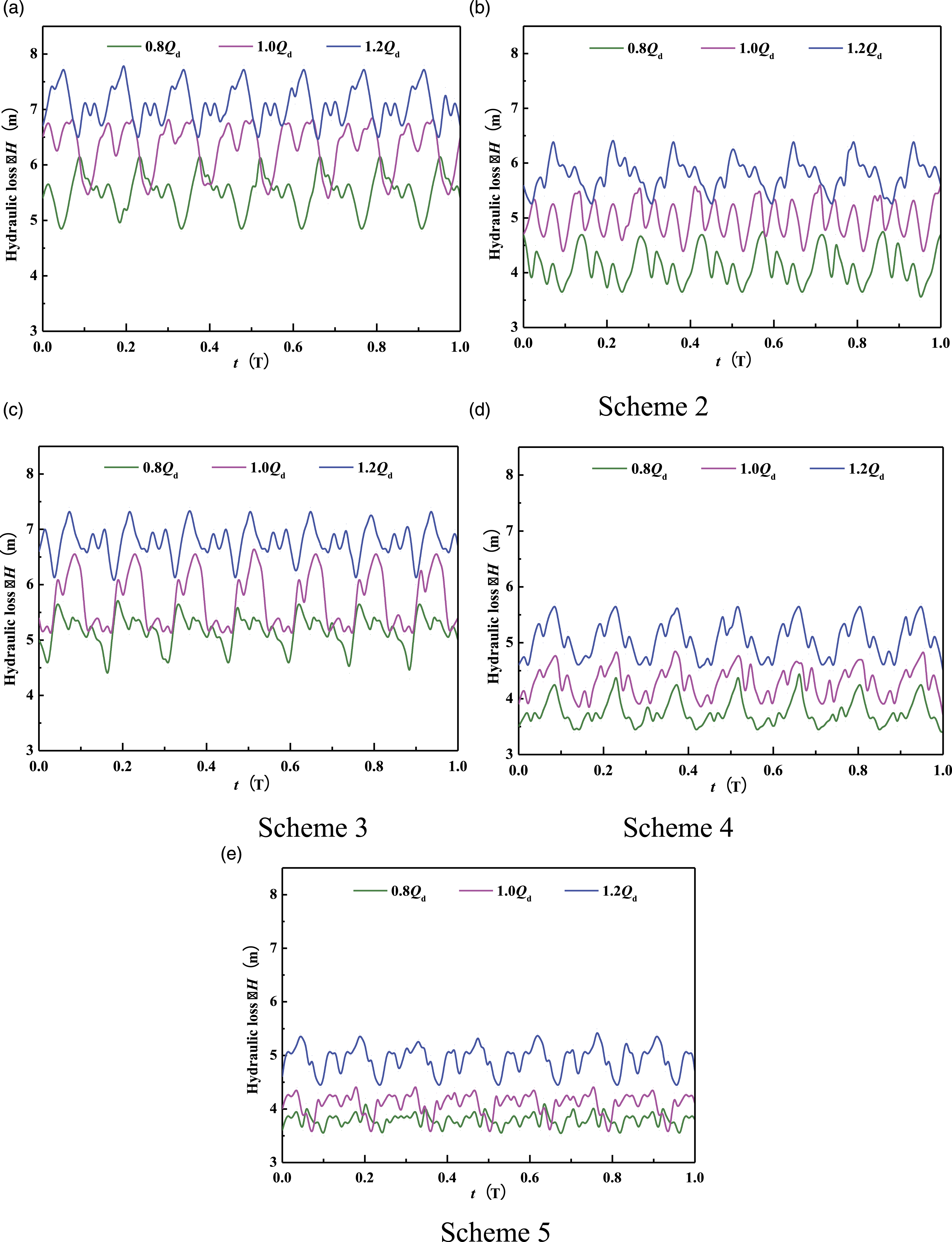
Through the numerical simulation of the various schemes of the diffuser, the internal flow field and flow loss of the diffuser are analyzed. The results show that the flow pattern of scheme 4 is the best and the hydraulic loss is less. Therefore, the optimal geometric parameters of the diffuser are as follows: Z=8, b3=24 mm, α3=16°, S=635 mm2, α6=94°.
Results and discussion
Comparison of external characteristic test
The optimized impeller and diffuser were hydraulically designed and processed into test pieces, as shown in Figure 11. And the optimized mine drainage pump has been tested for performance, and the test results are shown in Figure 12. The optimized impeller and diffuser. (a) impeller (b) diffuser. Comparison of hydraulic performance before and after optimization.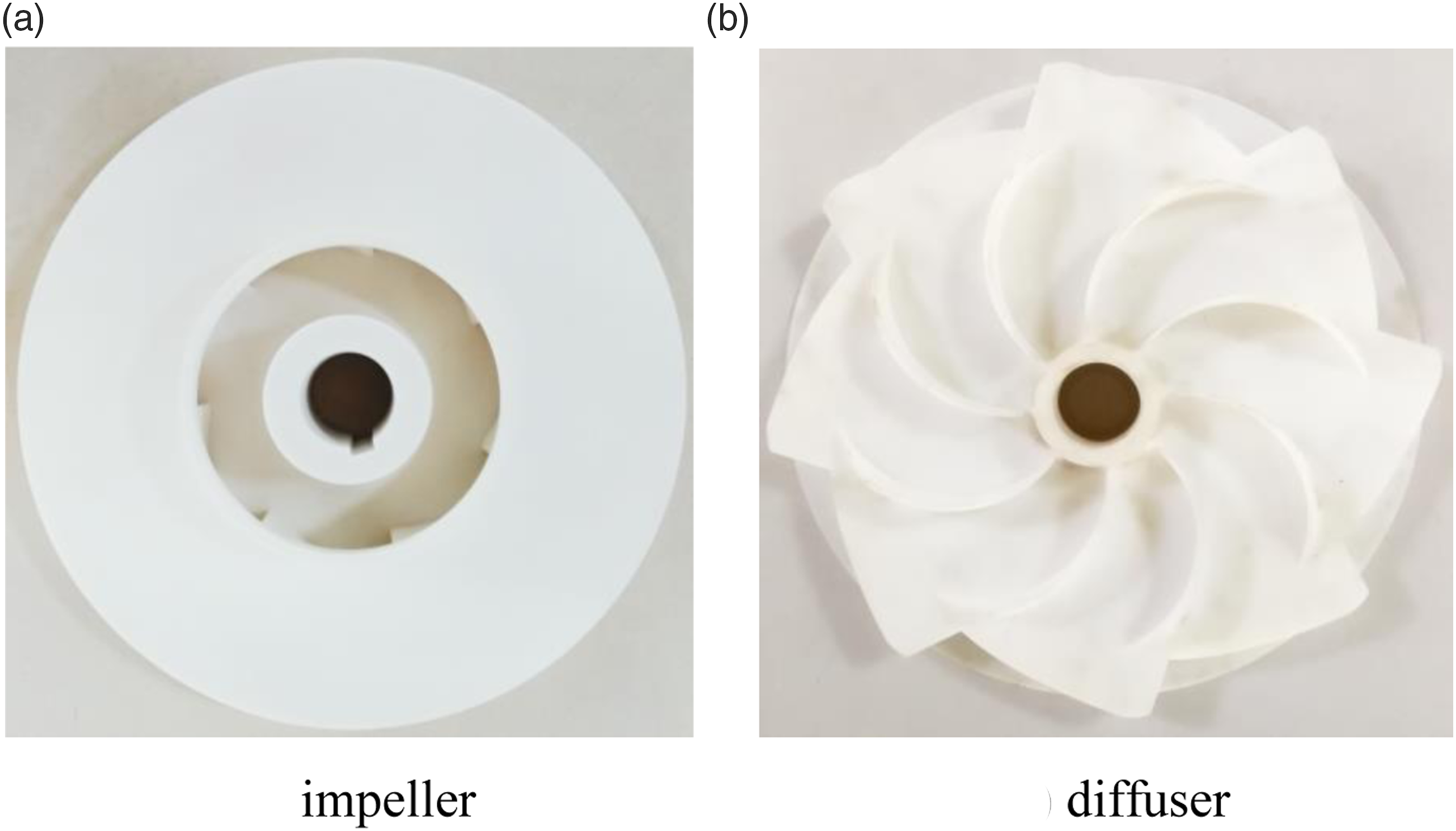
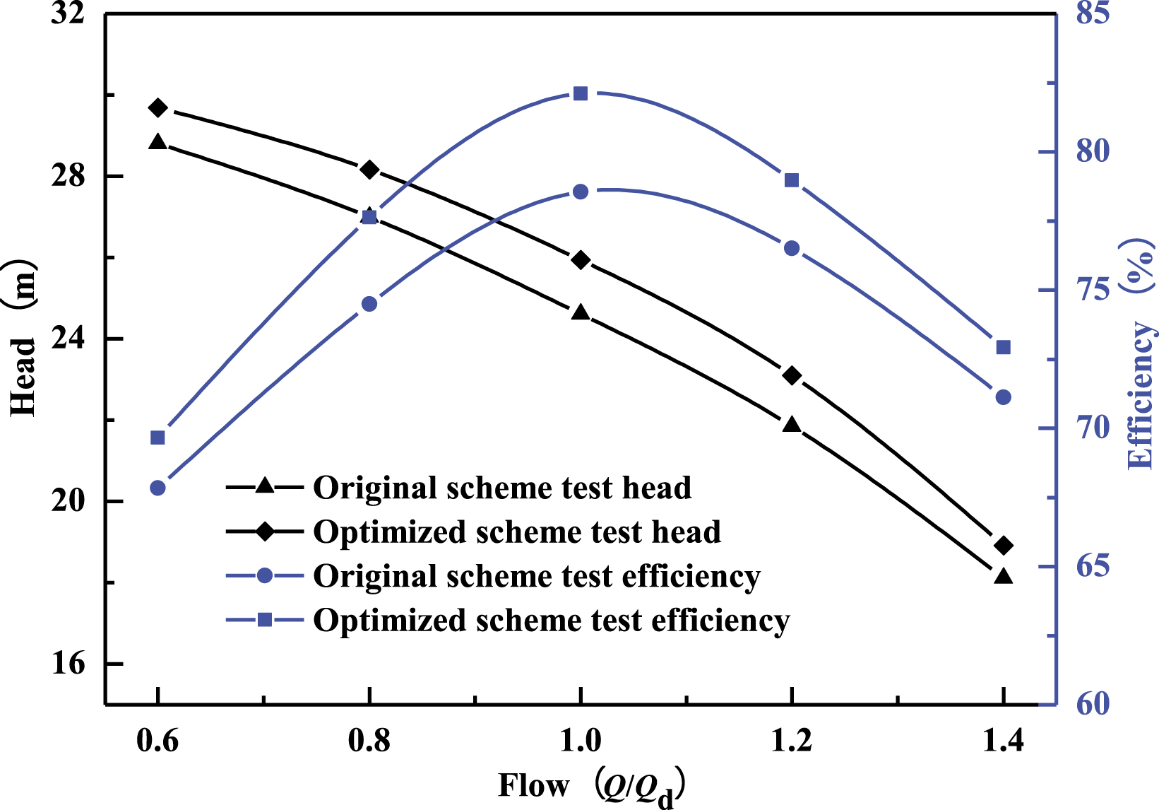
It can be seen from Figure 12 that the head and efficiency values of the optimized mine drainage pump are both greater than the experimental values of the original scheme. In particular, the optimized mine drainage pump efficiency test value under rated conditions is 82.11%, which is 3.58% higher than the original scheme, and the optimized head value is 25.94 m, which is 1.53 m higher than the original scheme. In addition, it shows that the optimized mine drainage pump meets the design requirements, improves energy utilization efficiency, and reduces economic costs.
Comparison of internal flow field distribution
Figure 13 shows the comparison of streamlines in the impeller before and after optimization. It can be seen from Figure 13 that under 0.8Qd, 1.0Qd, and 1.2Qd flow conditions, the blades of the original plan have low-speed vortex areas of different sizes on the unfolding surface, and the streamline distribution under 0.8Qd flow conditions is relatively turbulent, as the flow increases, the vortex area decreases. At the same time, the suction side of the blade appears to flow out under all working conditions, which indicates that when the impeller of the original scheme rotates at the rated speed, the coupling effect of the fluid flow line and the blade profile line in the impeller is poor, which increases the hydraulic loss in the impeller. And under larger flow conditions, the fluid in the impeller flow channel has obvious speed slip phenomenon. In addition, the streamline distribution in the optimized section is more even than the original scheme, and there is no obvious vortex in each working condition. The reason is that the optimized scheme has more blades, the distance between the blades is reduced, and the blade has a stronger ability to control the fluid. Due to the increase of the outlet width of the impeller after optimization, the extrusion condition of the fluid at the outlet of the impeller is improved, and the velocity slip of the fluid on the suction side to the pressure side decreases, indicating that properly increasing the outlet width of the impeller is beneficial to improve the velocity slip of the fluid at the outlet of the blade. The fluid velocity at the outlet of the blade has increased compared with that before optimization. At the same time, in a single flow channel, the fluid velocity gradient at the outlet has decreased compared with the original solution, and the distribution of the outlet velocity is more uniform, indicating that the larger blade after optimization The outlet angle is beneficial to the improvement of the flow pattern of the impeller. Comparison of impeller streamline distribution. (a) 0.8Qd (b) 1.0Qd (c) 1.2Qd.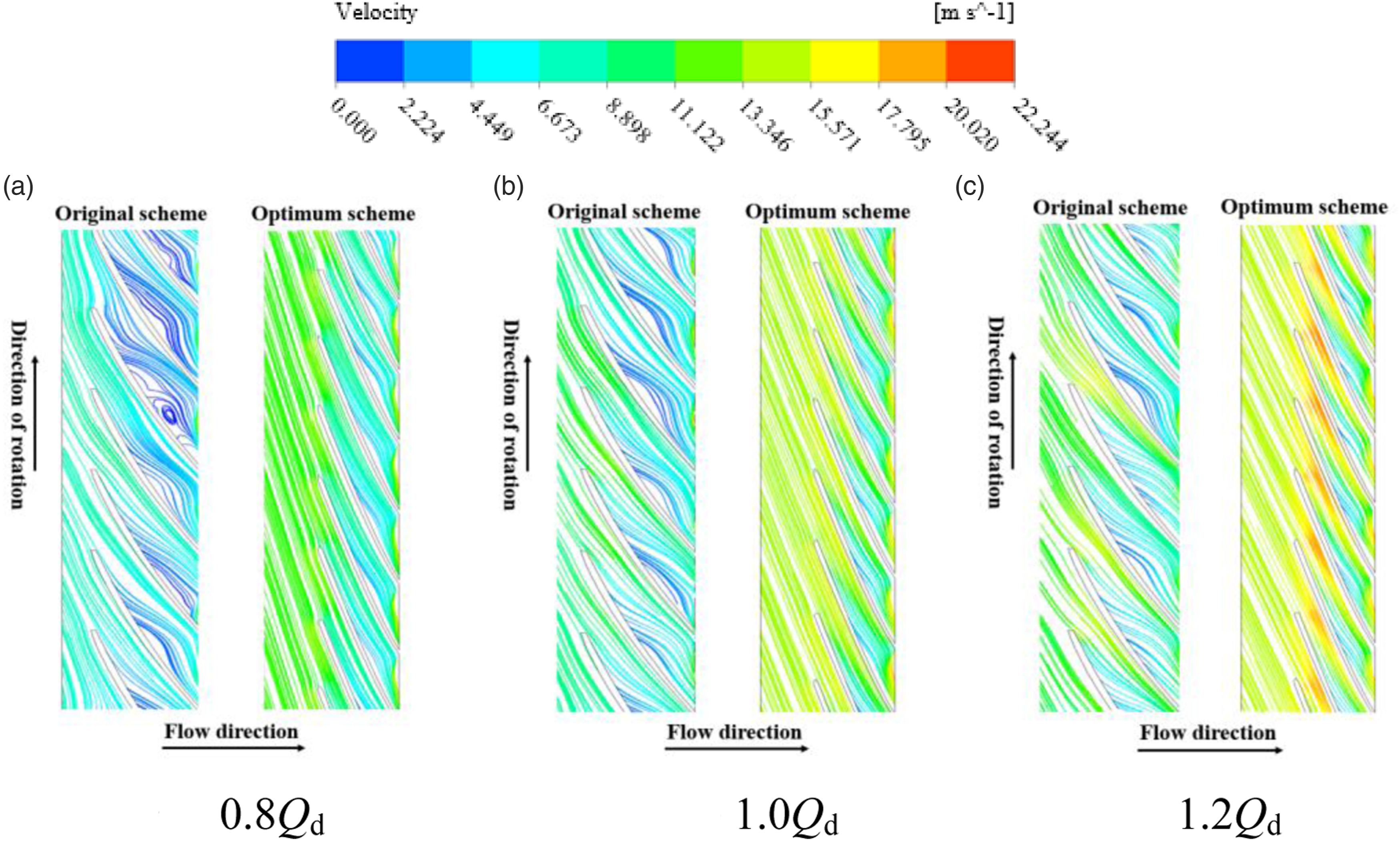
Turbulent kinetic energy is an indicator of the development or decline of turbulence in time and space, and also a sign of flow stability. Figure 14 is the comparison of the turbulent kinetic energy distribution in the axial section before and after optimization. From the figure, it can be seen that the overall turbulent kinetic energy in the cross-section of the mine drainage pump under 0.8Qd flow condition before optimization is small, and as the flow increases, the turbulent kinetic energy tends to increase. Under all working conditions, the maximum value of turbulent kinetic energy is distributed near the trailing edge of the impeller and the spiral section of the guide vane inlet. It may be that the distribution of turbulent kinetic energy of the fluid at the outlet of the impeller is greatly affected by the structural parameters of the impeller outlet. Compared with the original scheme, the turbulent kinetic energy of the optimized mine drainage pump is reduced in all working conditions, especially in the rated flow condition. This is mainly due to the improvement of the flow pattern in the impeller and diffuser, which reduces the turbulent loss in the pump. At the same time, there is no local high dissipation area in the optimized mine drainage pump under the condition of small flow rate, which indicates that the optimized guide vane and impeller have a good overall coordination, which is beneficial to improve the hydraulic efficiency of the pump. Comparison of turbulent kinetic energy distribution in axial section. (a) 0.8Qd (b) 1.0Qd (c) 1.2Qd.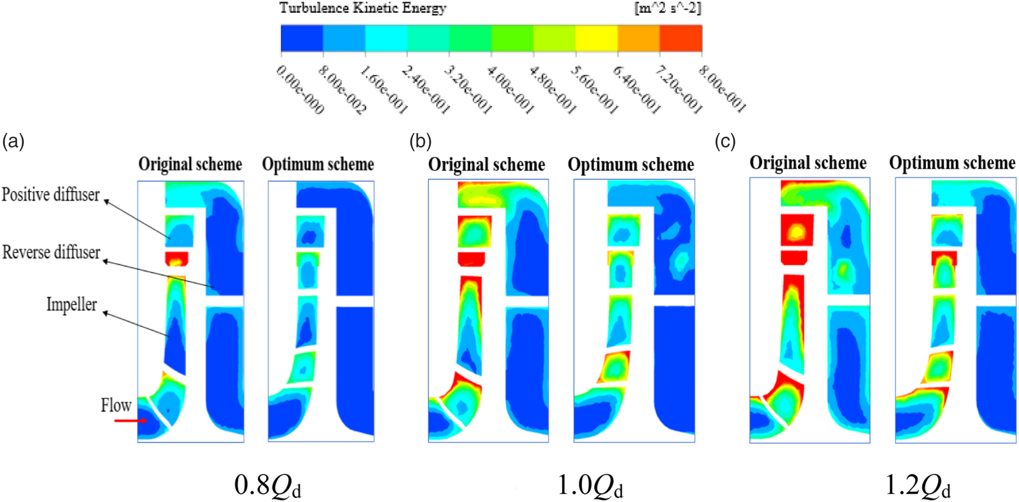
As shown in Figure 15, under the flow conditions of 0.8Qd, 1.0Qd and 1.2Qd, the axial section pressure distribution before and after optimization is compared. The figure shows that the pressure in the impeller has a certain gradient before and after optimization, and the pressure increases gradually from the impeller inlet to the impeller outlet. The pressure gradient at the impeller outlet after optimization is lower than that of the original scheme, and the pressure distribution is more uniform. The smaller pressure gradient after optimization can reduce the eddy current and the flow off phenomenon, and can improve the flow stability. Under the condition of small flow rate, due to the large pressure gradient at the interface between the impeller outlet and the diffuser inlet, it is easy to form a flow vortex area at the impeller outlet. With the increase of the flow rate, the static pressure value in the diffuser decreases more obviously after optimization, and the pressure gradient in the diffuser under all working conditions is reduced compared with the original scheme. Comparison of axial section pressure distribution. (a) 0.8Qd (b) 1.0Qd (c) 1.2Qd.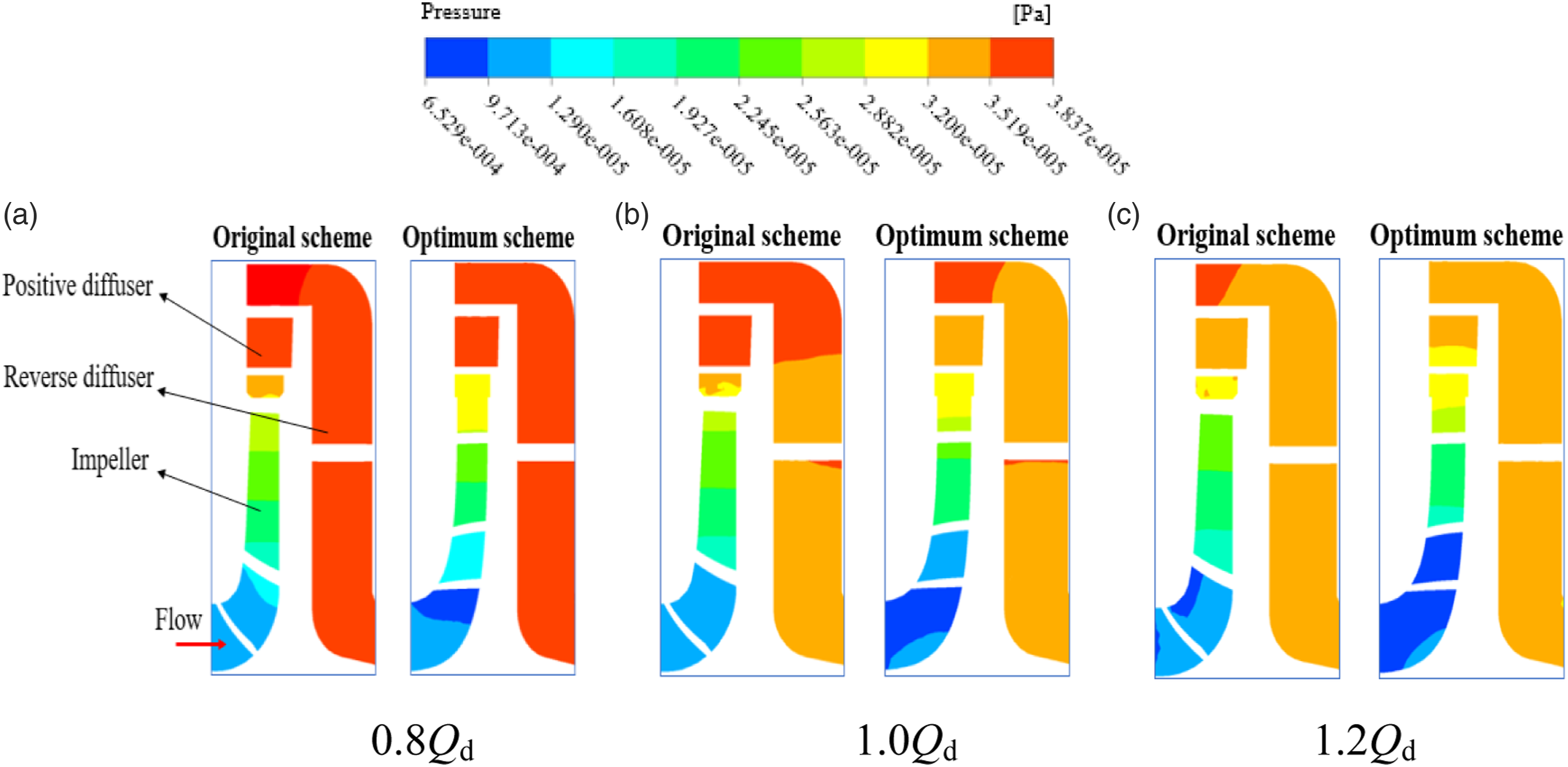
Comparison of radial force and axial force on impeller
Figure 16 shows that the radial force of the impeller decreases with the increase of the flow rate before and after optimization under the flow conditions of 0.8Qd, 1.0Qd and 1.2Qd, and the number of fluctuations and the number of blades in the radial force of the impeller in one cycle Unanimous. Compared with the original scheme, the radial force of the optimized mine drainage pump is reduced in all working conditions, and the average values are reduced by 22.4 N, 18.5 N and 13.1 N respectively. At the same time, because the overall pressure distribution in the impeller channel is more uniform after optimization, the radial load on the blade tends to be stable, and the radial force fluctuation of the impeller under the same working condition is reduced. It can be seen from Figure 17 that the maximum radial force under rated conditions is reduced from 110.9 N in the original scheme to 81.8 N. The decrease in the overall alternating load of the radial force of the mine drainage pump will be more conducive to the safe and stable operation of the pump system. Comparison of time domain diagrams of impeller radial force. (a) Original scheme (b) Optimum scheme. Comparison of average and maximum radial force on impeller. (a) Original scheme (b) Optimum scheme.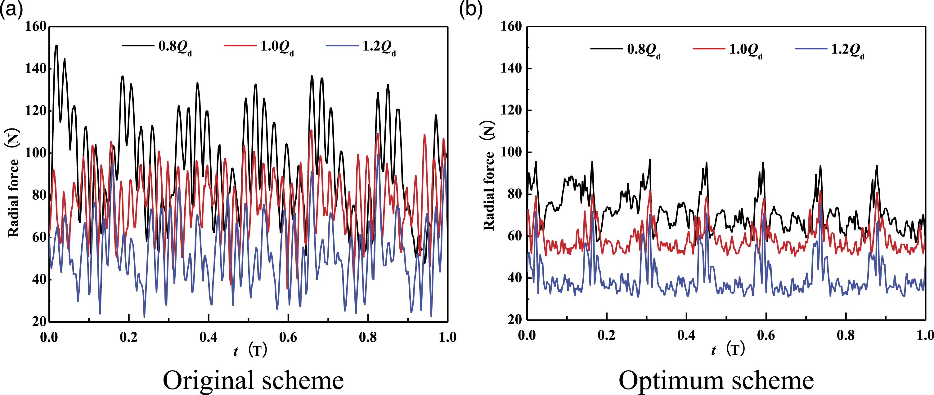
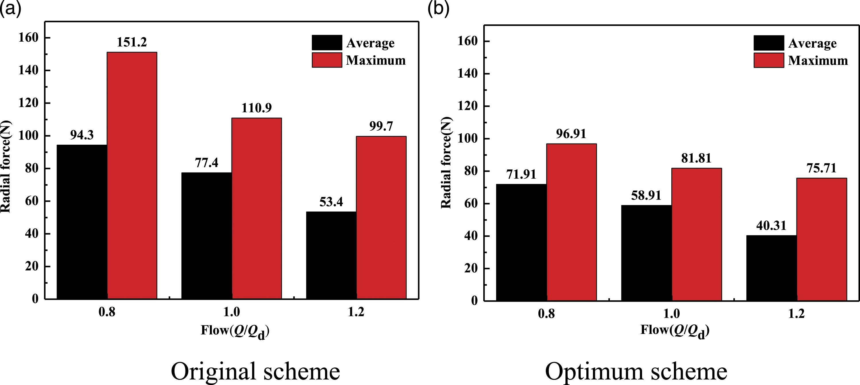
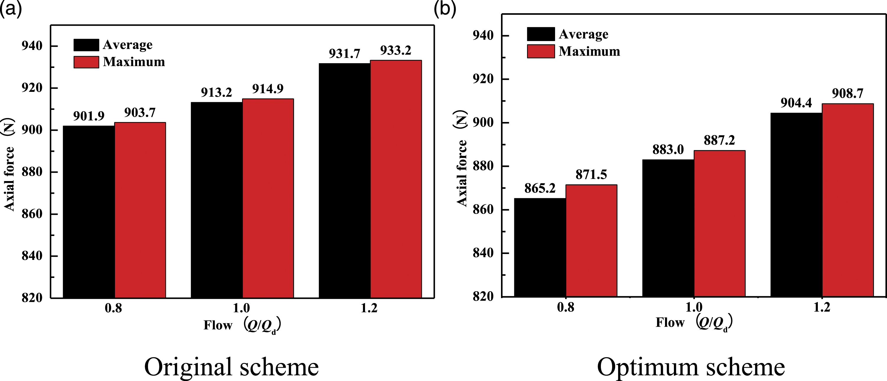
Figure 18 shows that the optimized axial force of the impeller under the flow conditions of 0.8Qd, 1.0Qd and 1.2Qd shows seven changing cycles, showing obvious dynamic and static interference characteristics. The average axial force of the original scheme and the optimized mine drainage pump increases with the increase of flow rate, but the average value is reduced compared with the original scheme in all working conditions. It can be seen from Figure 19 that the average axial force is reduced by 36.7 N, 30.2 N and 27.3 N respectively. The results show that the internal flow symmetry of the optimized mine drainage pump is higher, and the axial force in the pump is further offset, so that the axial load of the pump system is reduced, which is beneficial to prolong service life. Comparison of time domain diagram of impeller axial force. (a) Original scheme (b) Optimum scheme. Comparison of the average and maximum axial force on impeller. (a) Original scheme (b) Optimum scheme.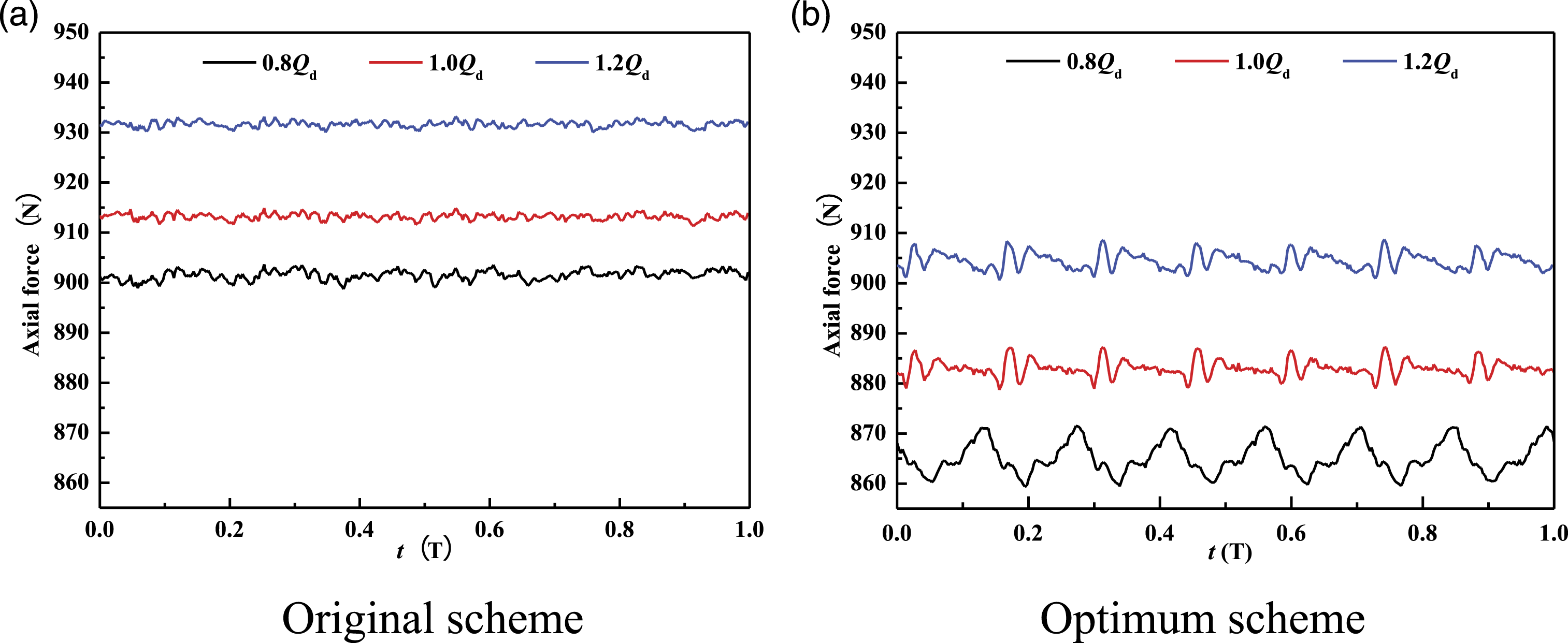
Conclusion
In this study, a high efficiency and large flow mine drainage pump was designed, and the mine drainage pump was tested. In order to improve the efficiency of mine drainage pump, the mine drainage pump was optimized, and the hydraulic performance before and after optimization was tested and compared. And in order to understand the internal flow mechanism of the mine drainage pump, the CFD method was used to numerically simulate the flow field of the mine drainage pump before and after optimization, and the simulation results were analyzed and compared. The main conclusions are as follows: (1) The impeller and diffuser before and after optimization were processed and tested. The test results show that the efficiency and head test values of the optimized mine drainage pump under rated conditions are higher than those before optimization, and the optimized results are 82.11% and 25.94 m respectively, which meet the design requirements and improve the energy utilization rate. (2) After optimization, the fluid falling off along the blade direction in the mine drainage pump is reduced, the fluid sliding trend from suction side to pressure side is decreased, and the fluid extrusion phenomenon at the impeller outlet is obviously improved compared with the original scheme. In addition, the pressure gradient in the flow channel of the mine drainage pump is significantly reduced compared with the original scheme, the fluid flow in the flow channel is smoother, the overall turbulent kinetic energy is also reduced, and the hydraulic loss is reduced. (3) Smaller diffuser inlet width and inlet placement angle will cause relative blockage at the diffuser inlet, which will affect the work of the pump impeller, but the inlet flow state of the optimized diffuser has been improved. Increasing the throat area of the diffuser properly can reduce the collision and vortex loss in the diffuser. (4) Under the flow conditions of 0.8Qd, 1.0Qd and 1.2Qd, the average radial force of the optimized impeller is reduced by 22.4 N, 18.5 N and 13.1 N respectively, and the average axial force of the optimized impeller is reduced by 36.7 N, 30.2 N and 27.3 N respectively. In addition, the amplitude fluctuation of the optimized radial force is reduced, and the amplitude fluctuation of the optimized axial force is small, which ensures the stable operation of the pump.
Footnotes
Declaration of conflicting interests
The author(s) declared no potential conflicts of interest with respect to the research, authorship, and/or publication of this article.
Funding
The author(s) disclosed receipt of the following financial support for the research, authorship, and/or publication of this article: The authors would like to thank the support by the National Natural Science Foundation of China (Grant no. 51979126)