
Abstract
Due to the complex structure and thin thickness of the guide vane edge of the hydraulic retarder impeller, the casting defects such as shrinkage porosity and misrun are usually formed during casting, which have a close relationship with the filling and solidification process. In this work, the filling and solidification processes of impeller in various gating systems, named case 1 to 3, were simulated and the distribution characteristics of potential shrinkage porosity defects were predicted by ProCAST software based on the mathematical models, boundary conditions, and parameters of investment casting. The simulation results show that the aim of complete filling of the impeller can be achieved by using all of the three gating systems. However, only the case 3 gating system consisted with one sprue riser and four feeding risers can provide the impeller with suitable feeding channel in melt solidification process. Therefore, no predicted shrinkage porosities form in the impeller because the defects can transfer to the gating system during solidification. The optimized gating system have been verified by experiment, and the rapid casting of the impeller has been realized by using 3D printed polystyrene patterns. The results of visual and X-ray inspections show that both the misrun and shrinkage porosity defects were eliminated in the actually final cast, which matched well with the numerical simulation results for the investment casting of the impeller. Many experiment results of the new product show that these optimization gating system are very helpful to reduce the casting defect and to improve the product quality.
Introduction
Investment casting is an important industry expertise and has been widely used in various manufacturing fields due to its advantages of high precision, high shape complexity, and good adaptability to various alloys.1–3 Singh and Singh 4 reviewed the development of this technique and demonstrated that the main steps of investment casting include wax mold pressing and assembly, mold preparation, dewaxing and mold baking, liquid metal pouring, mold cleaning and post-treatment of castings.
Since the beginning of 21st century, additive manufacturing (AM) technology has been greatly developed, which is used to produce metal, polymer and ceramic products with complex structure.5–7 The rapid investment casting based on AM process has also become widely accepted in casting foundries due to rapid production of patterns without any tooling requirements. Hague and Dickens 8 developed a new stereolithography build style that fully addresses the problems of investment casting with stereolithography models as patterns by providing an internal architecture for the stereolithography pattern. Wang et al. 9 introduced a method of design and topology optimization of 3D-printed wax patterns for rapid investment casting. The above improvements for pattern production allows the creation of freeform and highly complex geometries that are otherwise extremely difficult or too expensive to cast conventionally.
For castings with complex structures, the control of metallurgical defects is more important, because it will directly affect the mechanical properties and application reliability of castings. Therefore, it is necessary to find a way to predict and control the defects in the castings. Khan and Sheikh 10 has clearly pointed that casting simulations are capable of examining the effects of several casting parameters such as melt temperature, pouring time (velocity), gating and runner system design, riser design, mold configuration (single cavity or multi-cavity) in producing sound castings. Wang et al. 11 simulated the pouring process for the investment casting of 304 stainless steel impeller, which was proved helpful for the optimal gating location and sizing, location of feeder, or air vents. Li et al. 12 successfully produced a complex K418B turbine guide with vanes and ring structure by centrifugal casting process based on the results of ProCAST simulation.
Zhao and Yi 13 reported that the most easily formed defects in the impeller made by investment casting technology are shrinkage porosity and misrun at the edges of the guide vanes, which is mainly due to the unreasonable control of the filling and solidification of the melt in the mold. Therefore, the optimization designs of gating system and pouring process are very important to obtain high quality impeller. For castings with simple shapes, the gating systems can be designed according to experience, and qualified castings can be obtained. However, for castings with complex structures, it is necessary to use numerical simulation software to simulate a variety of gating systems, so as to select the most appropriate gating system, establish the best gating process, and try to avoid the occurrence of metallurgical defects of castings. By simulating the casting process, the number of trial and error can be greatly reduced, so as to improve the production efficiency and reduce the production cost.14–17
Hydraulic retarder is a kind of auxiliary braking device, which has the advantages of large braking torque, stable braking, low noise, long service life and small volume. 18 It can reduce the driving speed of the vehicle or make the vehicle stable within a certain speed range, which has become the focus of the transportation industry. 19 Liu et al. 20 introduced the working principle of the key component of the rotor impeller of the hydraulic retarder in detail. In comparison with the impellers used in other field,13,16 the impeller of the hydraulic retarder is much more complex and difficult to be manufactured by investment casting. It is due to that: (1) the impeller has many guide vanes with a forward angle (30°–45°) on each side and the space between two vanes is very narrow; (2) the thickness of vane edge is very thin (<1 mm), so it is very difficult to complete forming. In addition, the metallurgical quality of the impeller of the hydraulic retarder directly affects the safety of the truck. Therefore, the requirements for the defect control in the impeller are very stick.
In this work, the rapid investment technology process was firstly reported to be used for manufacturing rotor impeller of the hydraulic retarder. Numerical simulation method was used to research on the filling and solidification process of the complex stainless steel impeller of hydraulic retarder in consideration of various gating systems. The actual casting experiment was carried out to validate the simulation results and to analyze the defects appeared in the casting part.
Models description and experimental procedure
Filling and solidification process models
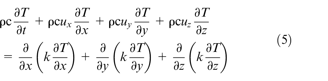
The filling process of metal melt is an unsteady viscous flow process of incompressible Newtonian fluid in the mold, 21 which is accompanied by the unsteady heat conduction process. It can be described by continuity equation, momentum conservation equation, energy conservation equation, and volume function equation. 22
Continuity equation:
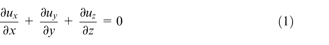
where
Momentum conservation equation:
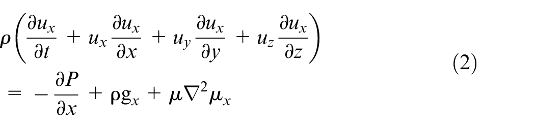
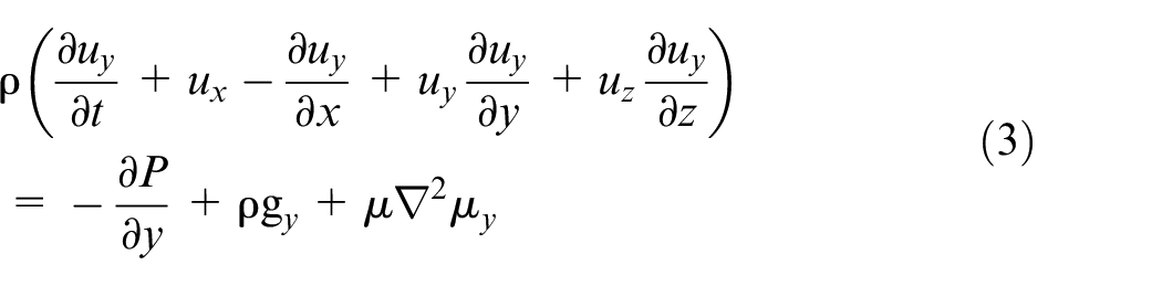
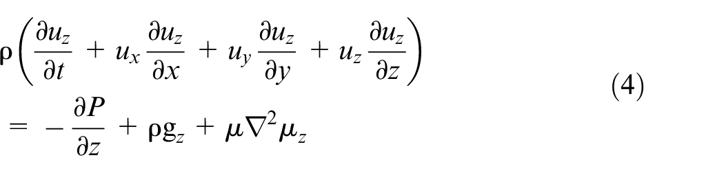
where
Energy conservation equation:
Where
Volume function equation:
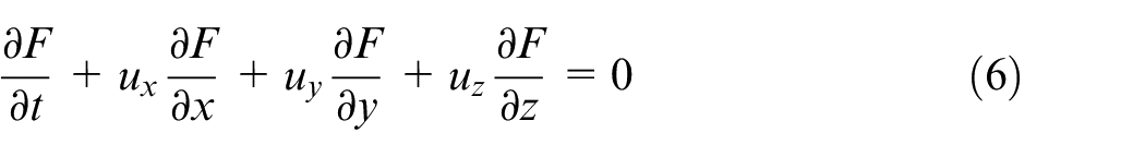
where
The solidification process of casting is generally calculated by using the finite element method based on nonlinear heat conduction. The nonlinear transient heat conduction equation is as the following:
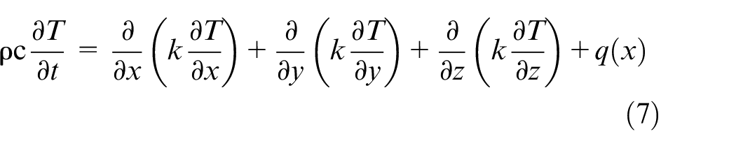
where
The treatment methods of solidification latent heat include temperature rise method, equivalent heat capacity method and enthalpy method.
23
In view of the solidification characteristics of stainless steel and the heat dissipation characteristics of investment casting, the enthalpy method is used to treat the latent heat of solidification, and the physical quantity enthalpy
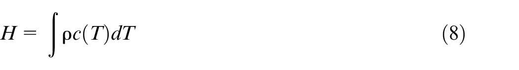
where
Gating system design and simulation parameter determination
The accuracy of numerical simulation of casting process is closely related to the setting of boundary conditions and the selection of thermophysical parameters of materials. In this study, a stainless steel named SAE 8620 was used to manufacture the impeller. As shown in Figures 1 and 2, the physical properties of this steel, such as the thermal enthalpy, thermal conductivity, solid fraction and viscosity with temperature were calculated by JMatPro software and then imported into ProCAST for the process simulation during investment casting of the impeller. The chemical composition of SAE 8620 stainless steel is listed in Table 1.
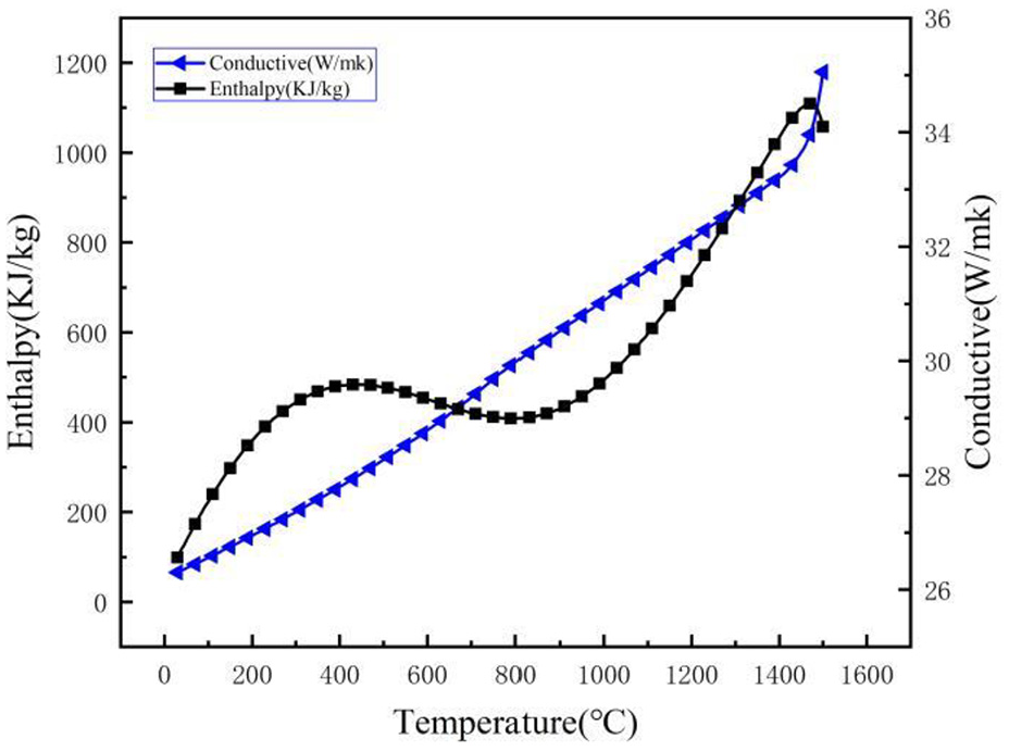
Thermal enthalpy and thermal conductivity of the SAE 8620 stainless steel.
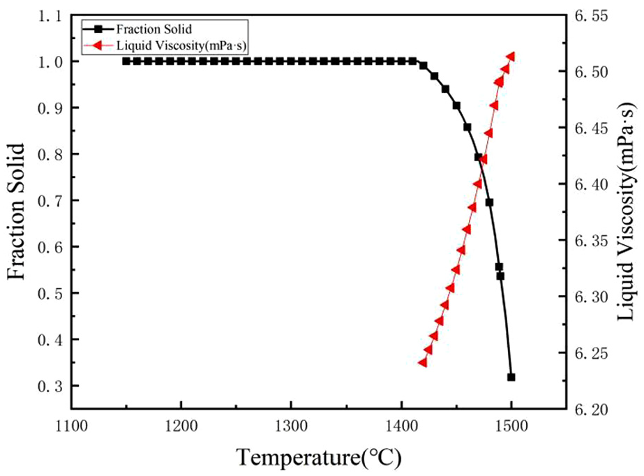
Solid fraction and viscosity of the SAX 8620 stainless steel.
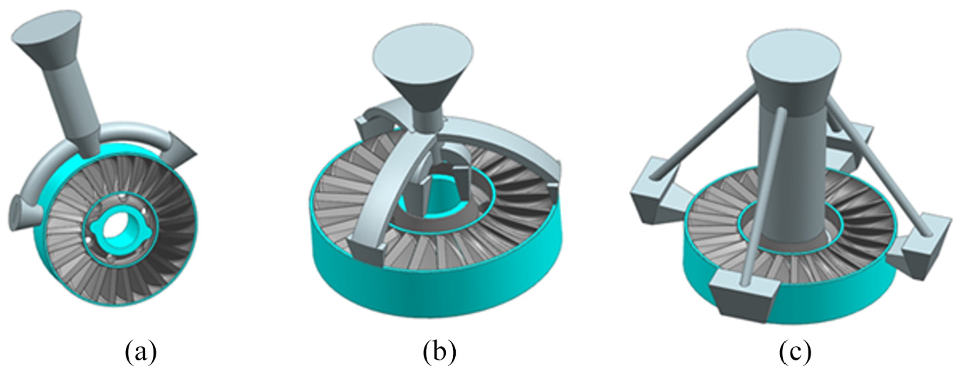
Nominal composition of SAE 8620 stainless steel (mass fraction/%).
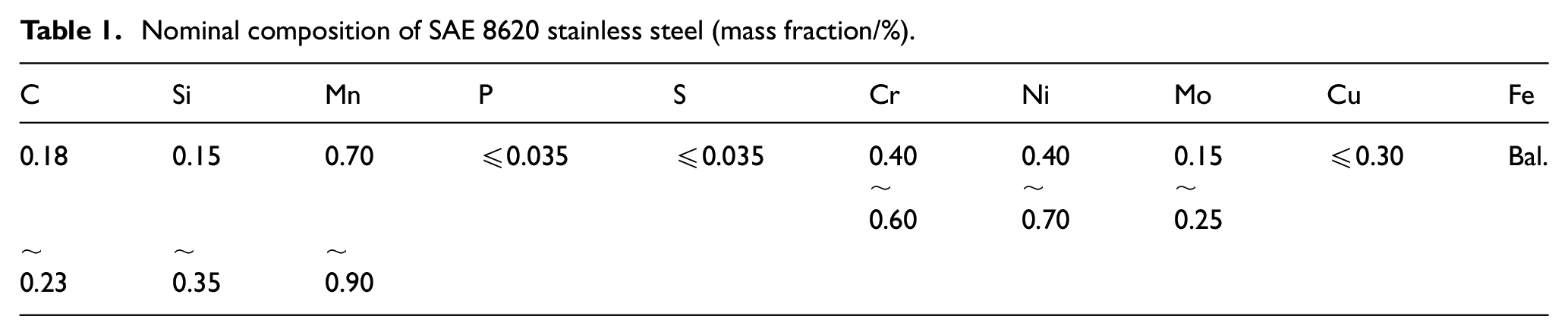
Gating system plays a role of supporting the whole pattern and mold. The alloy melt takes the gating system as the channel to form casting. The gating system not only guides alloy melt to fill the mold, but also undertakes the role of feeding the casting. The design of gating system has a direct impact on the quality and yield of castings. Considering the structural characteristics of the impeller, three top gating systems that are shown in Figure 3(a–c) were designed and their effects on eliminating shrinkage porosity defects in the impeller were compared by simulating the flow and solidification behavior of the melt during the investment casting. In case 1 as shown in Figure 3(a), the gate and runners were set on the side of the outer ring of the impeller. In case 2 as shown in Figure 3(b), the gate was placed directly above the center of the inner ring of the impeller, and the runners were connected with the edges of the inner and outer rings. In case 3 as shown in Figure 3(c), the runner connected with the gate was placed in the center of the inner ring, and four feeding risers were placed on the side of the outer ring.
Design diagrams of three gating systems; a–c cases 1–3, respectively.
The key factors that affect the accuracy of numerical simulation of the investment casting process are the setting of boundary conditions and selection of material parameters with much accuracy. The pouring velocity and temperature of the melt was 0.75 m/s and 1680°C, respectively. The mold preheated temperature was 1010°C, and the heat transfer coefficient was set as 1000 W/m2K. The cooling condition was air cooling. The mold thickness was set as 8 mm and mold material was set as calcined mullite (density: 3150 kg/m3). The thermal properties of the mold were selected from the database of the ProCAST software.
Pattern and mold preparations
In order to save mold cost and accelerate product development process, the polystyrene (PS) pattern was directly fabricated by selective laser sintering (SLS) after the three-dimensional CAD model of the impeller was designed and created. Figure 4(a) and (b) show the geometry dimensions and shape of the impeller PS pattern, respectively.
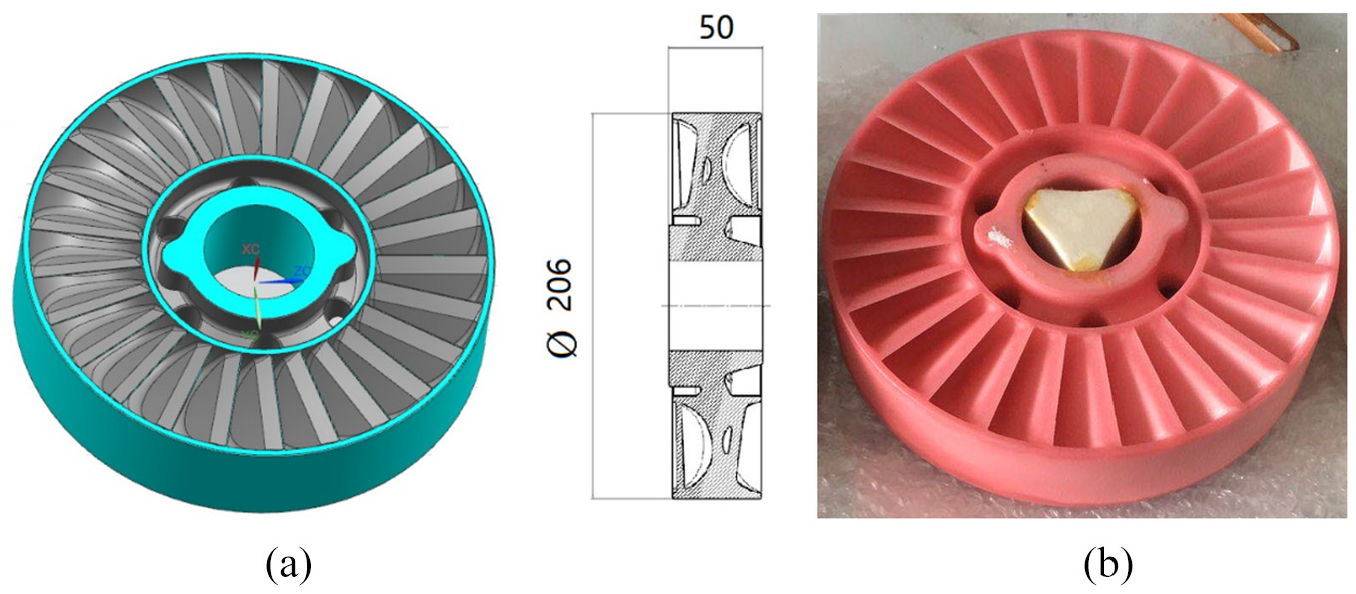
(a) 3D model and (b) SLS polystyrene pattern photo of the impeller.
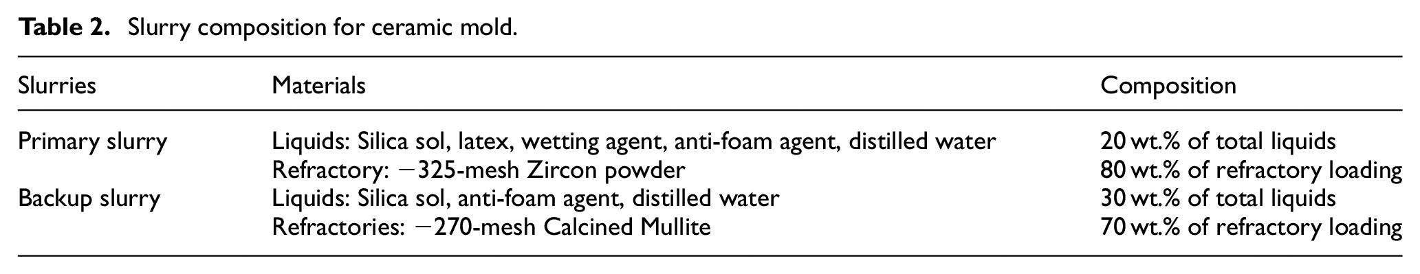
The ceramic mold applied in this study was designed to be representative of a standard mold used for stainless steel alloy. Details of slurry composition for mold building are given in Table 2. The primary slurry, which would ultimately be in contact with molten alloy, consisted of a colloidal silica binder (applied by Nalco Co. Ltd., USA), zircon filler (200–325 mesh, applied by Jiangsu Andake New Materials Co. Ltd., China), wetting agent (applied by Nalco Co. Ltd., USA) and anti-foam (applied by Nalco Co. Ltd., USA). The backup slurry consisted of a colloidal silica binder (applied by Nalco Co. Ltd., USA), calcined mullite filler (325 mesh, applied by Anhui Jinyan Kaolin Co. Ltd., China) and anti-foam (applied by Nalco Co. Ltd., USA).
Slurry composition for ceramic mold.
The mold was made by first investing the PS pattern into the primary slurry. A zircon stucco (80−120 mesh, applied by Jiangsu Andake New Materials Co. Ltd., China) was applied by the rainfall sanding method. The pattern was rotated to achieve an even coating of stucco material, which adheres to the surface of the wet slurry. This coat was dried at a temperature of 25 ± 1°C and 55 ± 5% relative humidity for 24 h. Six backup coats were then applied. Coarse calcined mullite stuccos of 30−60 mesh and 16−30 mesh were used as the first backup stucco and the following backup stucco, respectively. Each backup coat was dried at a temperature of 25 ± 1°C and 55 ± 5% relative humidity and 3 ± 0.5 ms−1 air speed for 8 h. Finally, a seal coat of backup slurry was applied and dried at a temperature of 25 ± 1°C and 55 ± 5% relative humidity and 3 ± 0.5 ms−1 air speed for 8 h. The PS pattern inside the ceramic mold was then removed by directly burning in a sintering furnace at 800°C for 2 h under atmospheric conditions.
Experimental verification and casting characterization
A pouring furnace was used to fabricate the SAE 8620 stainless steel impellers under gravity in air. Firstly, after pre-heating the mold on the sintering furnace at 1010°C for 8 h, the mold was transferred into the pouring furnace. Secondly, the SAE 8620 stainless steel melt in a crucible was poured into the mold. Thirdly, the mold containing the stainless steel melt was cooled to room temperature. Finally, the mold was completely removed and sand-blasting was carried out on the surface of the castings. The filling state of the guide vanes was observed by visual measurement and shot by a digital camera. The impeller was detected by using X-ray method and the microstructures of the impeller was analyzed by means of metallographic microscope.
Results and discussion
Flow analysis for various gating systems
The thickness of the guide vane edge on both sides of the hydraulic retarder impeller is only 0.7 mm, so the misrun defect that is easily formed at the guide vane edge is one of the main risks leading to the casting failure of the impeller. One of the ways to reduce the misrun defect is to make the melt pour quickly and fill the mold in the shortest time in order to maintain good flow ability of the melt. Therefore, the filling speed, flow direction and temperature of the melt become the main factors that determine the quality and performance of the casting.
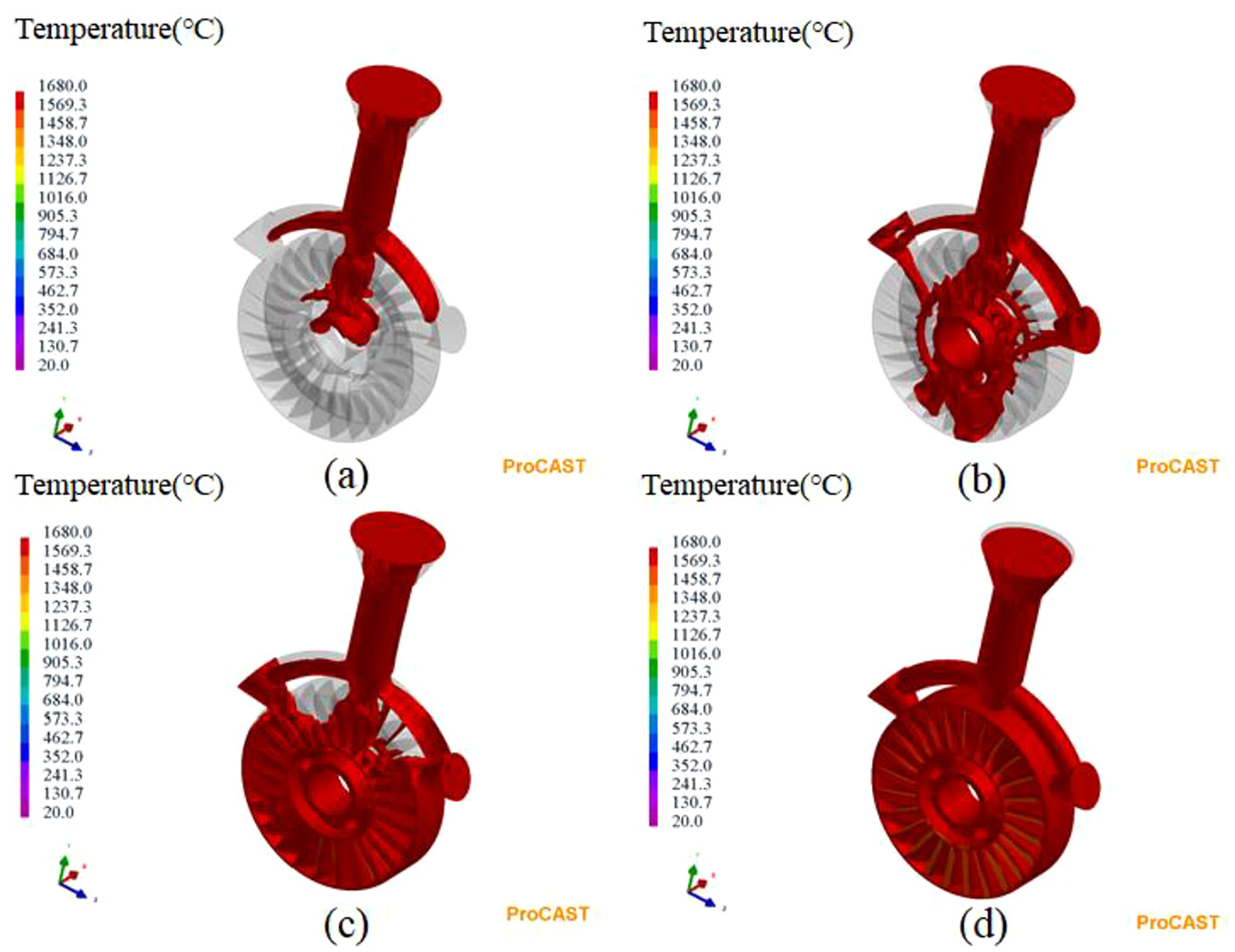
Figure 5 shows the mold filling simulation process of the melt in case 1. It can be seen from Figure 5 that the melt first flows into the transverse sprue and the inner ring (Figure 5(a)), then flows into the lower part of the outer ring (Figure 5(b)) under the action of gravity, then fills the mold steadily from the bottom to the top (Figure 5(c)), and finally fills the whole impeller and gating system (Figure 5(d)). The whole filling process within 5 s is smooth without splashing and obvious turbulence. Figure 6 shows the mold filling simulation process of the melt in case 2. As shown in Figure 6, the melt firstly flows into the flange through the gate (Figure 6(a)), and then gradually fills the bottom of the impeller (Figure 6(b)). Subsequently, the melt evenly fills the mold from bottom to top (Figure 6(c)). Finally, the impeller and gating system are filled completely by the melt. The whole filling time is also 5 s. It can also be observed from the filling process in case 2 that uneven flowing behavior of the melt appears at the beginning of pouring due to the high pouring speed. Figure 7 shows the mold filling simulation process of the melt in case 3. It can be seen from Figure 7 that the melt firstly flows into the inner ring of the impeller (Figure 7(a)), and then entered the vanes swiftly (Figure 7(b)). After that, the melt flows into the outer ring and four feeding risers (Figure 7(c)). Finally, the melt fills the entire mold. The whole filling process in case 3 also takes 5 s. Meanwhile, the introduction of the gating system in case 3 reduces fluctuations in the flow velocity and splashing during the filling process. Based on the above simulation results, it can be seen that the complete mold filling of the melt, including the position of guide vane, can be realized by using the three kinds of gating systems.
Filling process of alloy melt in case 1: (a) 1.1 s, (b) 1.8 s, (c) 3.6 s, and (d) 5.0 s.
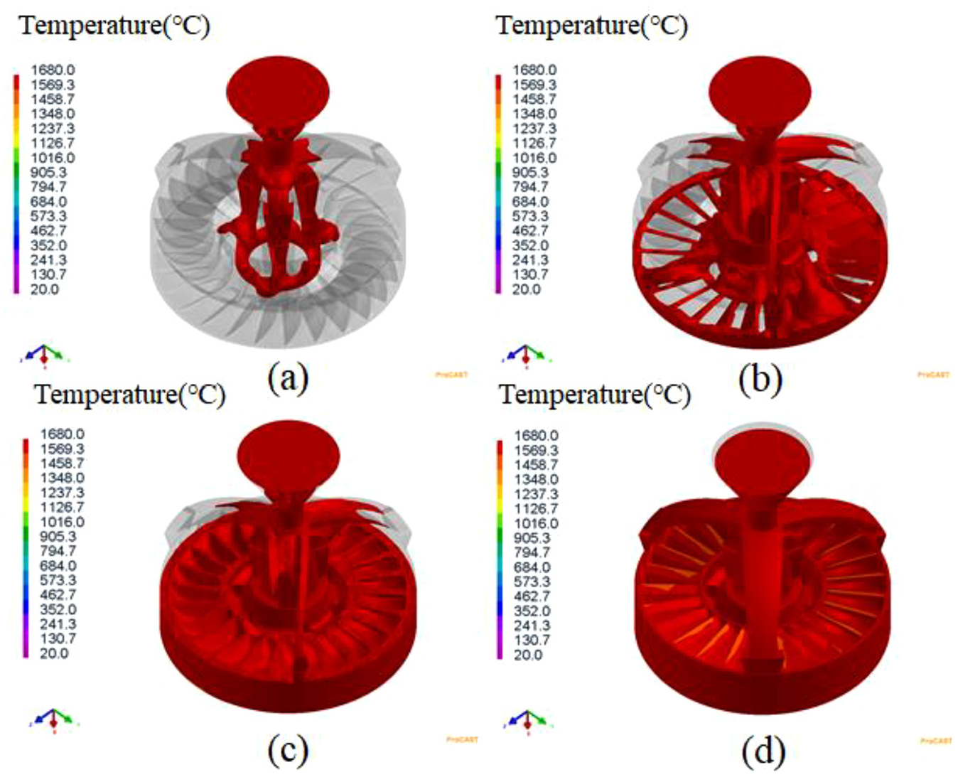
Filling process of alloy melt in case 2: (a) 1.1 s, (b) 1.8 s, (c) 3.6 s, and (d) 5.0s .
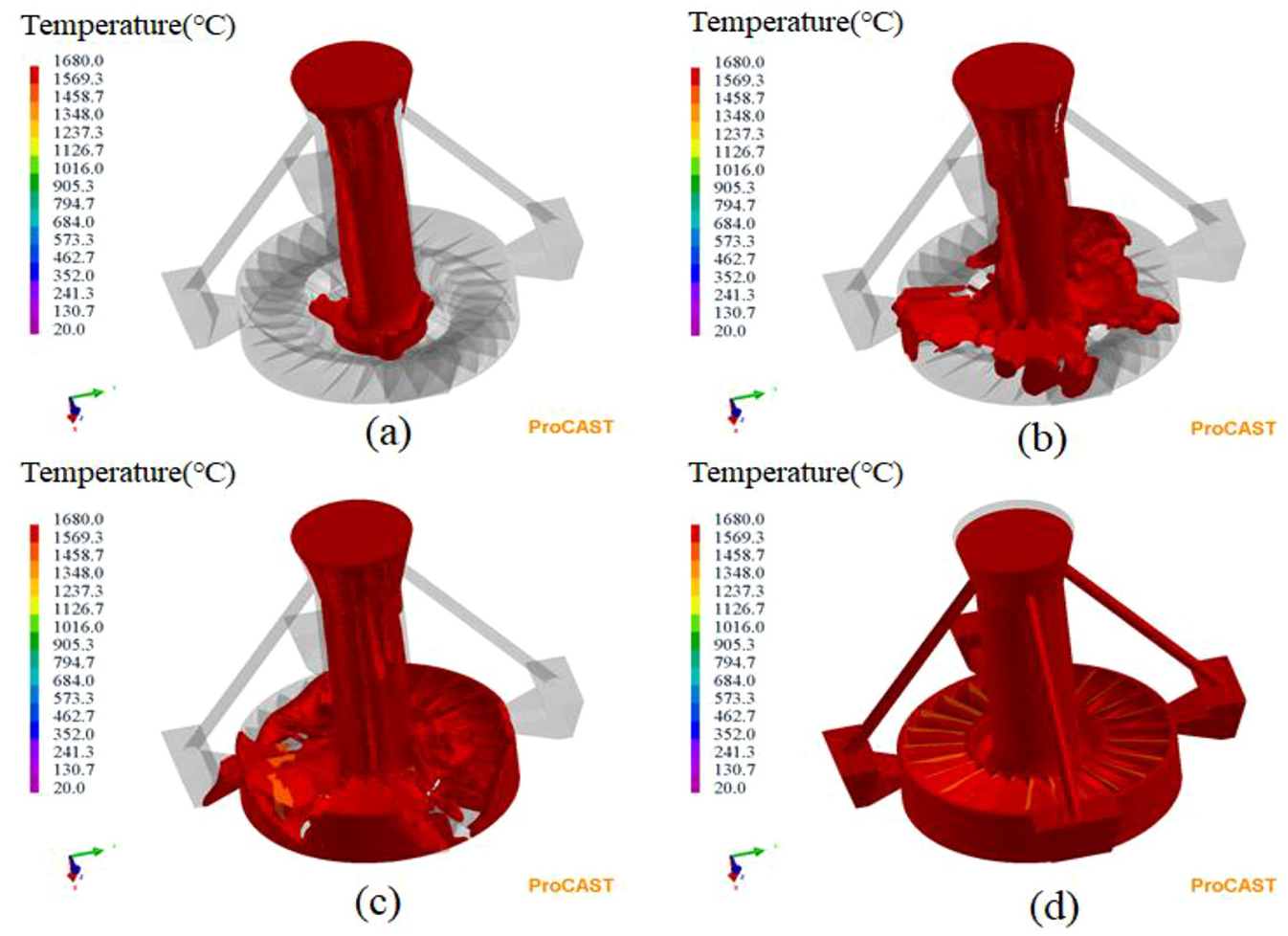
Filling process of alloy melt in case 3: (a) 1.1 s, (b) 1.8 s, (c) 3.6 s, and (d) 5.0 s.
Solidification time distribution analysis
Figure 8 shows the distribution of solidification time in the investment casting process for the impeller in case 1 to 3. From Figure 8(a), it can be seen that the solidification time distribution of the impeller in case 1 is uneven extremely due to the mold filling process as shown in Figure 5, which might lead to serious shrinkage porosity defect in the impeller. From Figure 8(b), it can be seen that the solidification time inside the impeller is slightly longer than that outside. However, the sprue runner connected with the gating cup has the similar solidification time with the impeller body, which means that the casting may not get enough feeding during solidification and form shrinkage porosity defects inside. It can be seen from Figure 8(c) that the solidification time in case 3 gradually increases from the outside to the inside of the impeller, while the solidification time of the vertical sprue is the longest, thus forming a reasonable solidification time gradient distribution from the vertical sprue to the outer ring, which is conducive to the feeding of the melt.
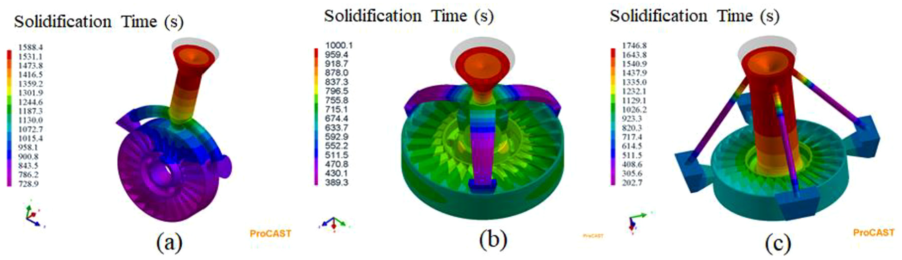
Solidfication time distributions of the impeller in case 1 to 3.
Solid fraction and shrinkage porosity analysis
It is well known that the isolated melt regions surrounded by the solid phase in castings are the main sources that caused the shrinkage porosity defect due to insufficient feeding channels of the metal melt. The solid fractions of the impeller in case 1 to 3 at different stages are shown in Figures 9 to 11, respectively. As shown in Figure 9, the edges of the guide vanes, the outer and inner rings of the casting are the regions where solidification occurs earlier, which leads to the formation of an obvious isolated melt region between the guide vanes and inner ring. This indicates that the shrinkage porosity probably formed in this region (Figure 9(c)) in case 1. The similar simulation results can also be obtained in case 2. As shown in Figure 10, the solid fraction of the region between guide vanes and inner ring is much lower than the inner ring that is connected with the sprue runner (Figure 10(c)), which means no alloy melt can feed that region and serious shrinkage porosity may form in the casting. In case 3, there is no isolated melt region appear in the impeller body and the last solidified regions are the vertical sprue and four risers located in the outer ring (Figure 11(c)). This indicates that the shrinkage porosity can transfer from casting to gating system.
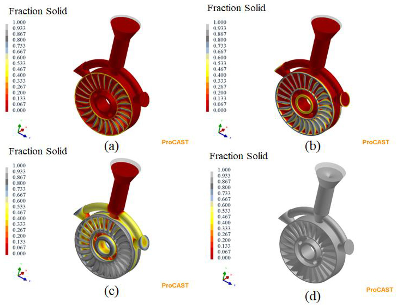
Solid fraction of the impeller in case 1: (a) 9.3 s, (b) 16.7 s, (c) 43.1 s, and (d) 1000.3 s.
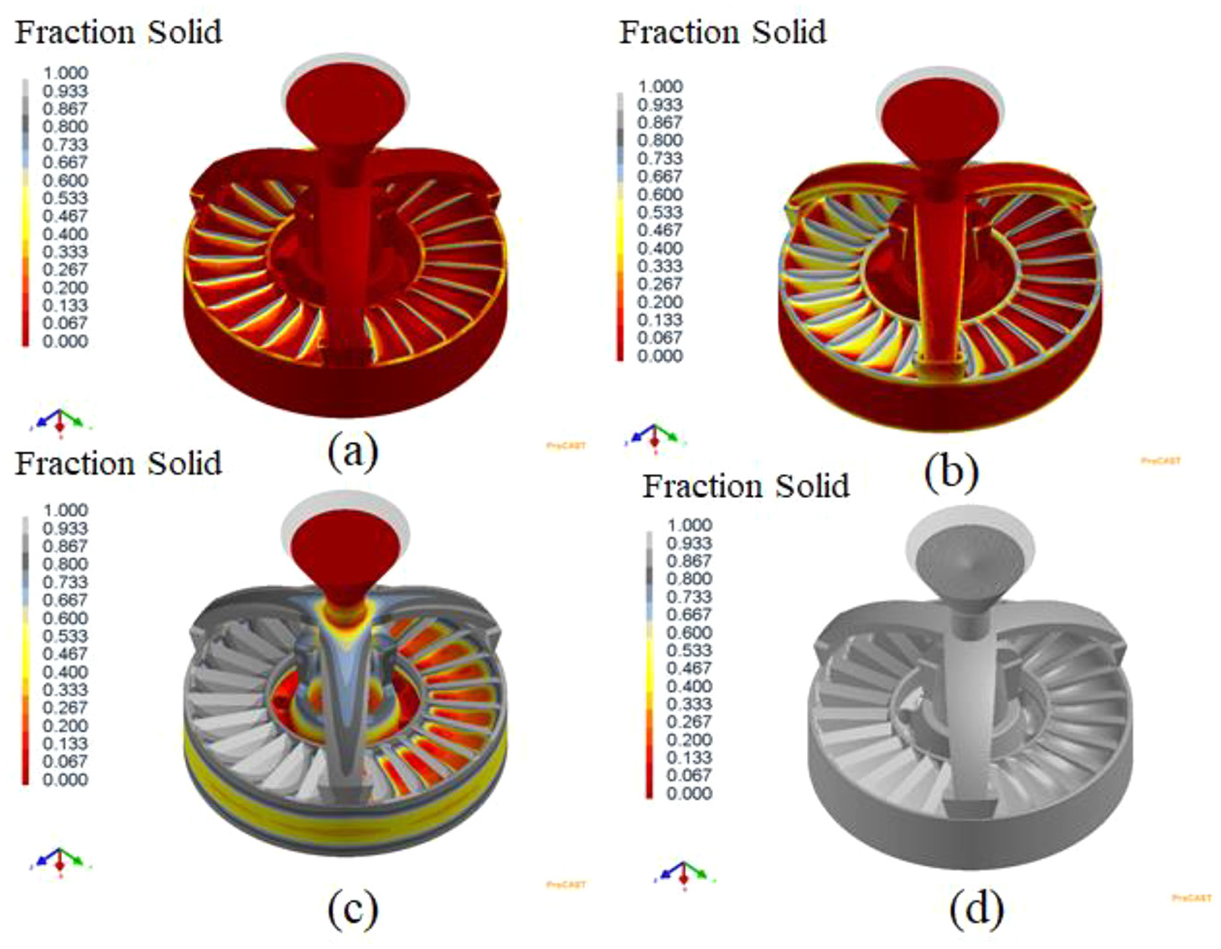
Solid fraction of the impeller in case 1: (a) 9.3 s, (b) 16.7 s, (c) 43.1 s, and (d) 1000.3 s.
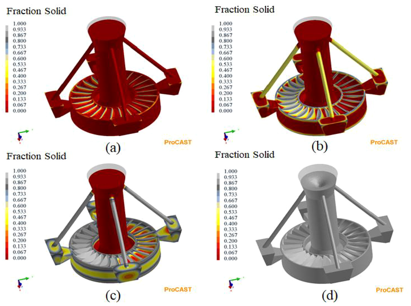
Solid fraction of the impeller in case 1: (a) 9.3 s, (b) 16.7 s, (c) 43.1 s, and (d) 1000.3 s.
Figure 12(a)–(c) shows the predicted shrinkage porosity defects with various gating systems in case 1 to 3, respectively. As expected, some large shrinkage porosities appear in the region between guide vanes and inner ring, and a few small shrinkage porosities are distributed on outer ring flange of the impeller in case 1 and 2, as shown in Figure 12(a) and (b), respectively. Compared with the above cases, there is no shrinkage porosities formed in the impeller in case 3 as shown in Figure 12(c), which indicates that the gating system in case 3 can well avoid the formation of shrinkage porosities during the casting process.
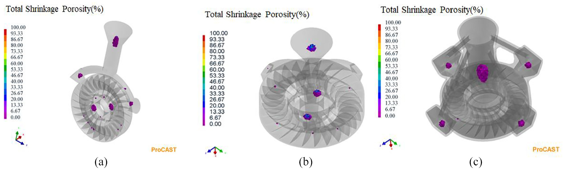
The predicted shrinkage porosities with different gating systems in cases 1–3.
Experimental verification
In this study, a gravity casting furnace was used to realize the melt pouring of the impeller in air. The process was set as follows: the mold with a gating system in case 3 was placed in a sand box, filled with 0–3 mm coal gangue sand, and then the sand box was placed in the mold pre-heating furnace. After being pre-heated at 1010°C for 8 h, the sand box with the mold was moved under the crucible of the gravity casting furnace. The melting temperature of SAE 8620 stainless steel was set as 1680°C. After pouring the melt into the mold, the impeller casting was cooled naturally to room temperature. The mold, as-casted and sandblasted impeller were photographed as shown in Figure 13(a)–(c), respectively. It can be seen from Figure 13(c) that the guide vanes as well as the inner and outer rings of the impeller were filled completely, no visible misrun defect appeared at the edge of the guide vanes under the condition of gravity casting. In order to evaluate the effect of the gating system in case 3 on the eliminating the shrinkage porosity defects, the impeller was detected by X-ray and the results show that no shrinkage porosities were found in the guide vanes, outer and inner rings. Figure 14 shows the metallographic photographs of the samples cut from the sprue riser, guide vane, outer ring and inner ring of the impeller. It can be seen from Figure 14(a) that there were clustered shrinkage porosity defects in the sprue riser, while no obvious defects could be observed in other parts of the impeller as shown in Figure 14(b)–(d).
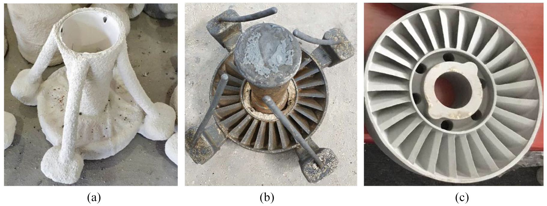
Photos of (a) mold, (b) as-casted impeller, and (c) sandblasted impeller.
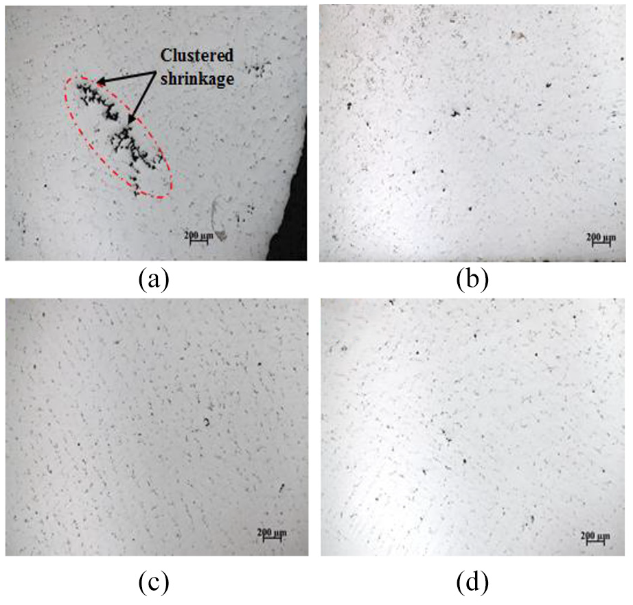
Metallographs of samples cut from: (a) riser, (b) guide vane, (c) outer ring, and (d) inner ring of the impeller.
The experimental results of impeller casting were in good agreement with the simulation results, but the pouring conditions given in this experiment were not necessarily the best pouring conditions. In the future work, it is necessary to further design and simulate the pouring process. On the premise of ensuring the integrity of vane edge filling, it is not only necessary to eliminate the defects such as shrinkage porosity in the impeller, but also to obtain finer grains to improve the overall mechanical properties of the impeller.
Conclusion
In the present work, a stainless hydraulic retarder impeller with complex geometry was developed by combining 3D printing and simulation optimization. The main contributions of this paper are as follows:
According to the structural characteristics of the impeller, three top gating systems have been designed and named as case 1, case 2, and case 3, respectively. Based on the melt flowing field and isolated melt regions, the defects are analyzed in the casting. The results of the flow analysis under gravity casting process exhibits that the SAE 8620 stainless steel melt can fill the mold completely in case 1 to 3. The introduction of the gating system in case 3 reduces fluctuations in the flow velocity and splashing during the filling process.
The simulation results for shrinkage porosities of the impeller show that some large shrinkage porosities form in the region between the guide vanes and inner ring due to the existence of isolated melt in that region in case 1 and 2. By comparison, no shrinkage porosities form in the impeller due to that the gating system in case 3, while the shrinkage porosities transfer to the gating system. The gating system in case 3 can provide the impeller with suitable feeding channel in the process of melt solidification.
The actual pouring result shows that the impeller was completely filled with mold and no visible misrun and shrinkage defects formed in the impeller by using the gating system in case 3. Meanwhile, the predicted shrinkage porosity defects matched well with the X-ray test results, which further proved that such a gating system was suitable for the casting of the complex impeller of the hydraulic retarder. However, the pouring process need to be further optimized in order to less the grain size and improve the mechanical properties of the impeller.
Footnotes
Acknowledgements
The authors thank Mr Qili Chen for the guidance in the analysis of the experimental results of this paper.
Declaration of conflicting interests
The author(s) declared no potential conflicts of interest with respect to the research, authorship, and/or publication of this article.
Funding
The author(s) disclosed receipt of the following financial support for the research, authorship, and/or publication of this article: This research was funded by the National Science and Technology Major Project “Aero engine and Gas Turbine” (2017-VII-0008-0102), the Opening Foundation of the National Key Laboratory of Rare Metal Specialty Materials (SKL2018K001), the Special Fund Project for Independent Innovation of AVIC (ZGHF-ZL-2017-C078), the Major State Basic Research Development Program of China (2016YFB0701405), the National Natural Science Foundation of China (51705314) and the Startup Fund for Youngman Research at SJTU (18X100040025).