This study is concerned with the development of multi-input multi-output control algorithms for the active vibration suppression of structures using accelerometer signals and force-type actuators. The concept of the single-input single-output virtual tuned mass damper control algorithm developed in the previous study was extended to cope with multiple natural modes of structure equipped with a limited number of sensors and actuators. Two control algorithms were developed based on the assumption of collocated control. One is the decentralized virtual tuned mass damper control that produces the actuator signal using only the accelerometer signal of that actuator position. The other is the centralized virtual tuned mass damper control that is designed in modal-space, and produces the modal control force using the modal coordinate. Both the theoretical and experimental results show that the proposed control algorithms are effective in suppressing multiple natural modes with a lesser number of sensors and actuators. However, the decentralized virtual tuned mass damper control can be designed and implemented more easily than the centralized virtual tuned mass damper control.
Recently, the active vibration control (AVC) technique is used as a means of more effectively suppressing vibrations that have a negative effect on humans and structures. The active vibration controller consists of a sensor that measures vibration, an actuator that suppresses the vibration, and a control algorithm that calculates the control force based on the sensor signal, thus forming a closed-loop control system. Naturally, the control algorithm depends on the type of sensor and actuator. Above all, the control algorithm should not cause instability in the structure, even if the sensor value becomes abnormal, or the actuator malfunctions. The most essential part in applying the AVC is the control algorithm. Over the decades, many control algorithms have been developed and proposed for the AVC.1 However, there are not many AVC algorithms using accelerometers, which are the most used equipment for vibration measurement.2–4
For vibrations caused by impact-type disturbance or a periodic excitation force whose excitation frequency is close to a natural frequency, it is most effective to reduce the resonant amplitude of the natural vibration mode. Hence, the AVC is designed to tackle that natural mode, and to increase damping. If the displacement sensor, such as a piezoelectric sensor, and force-type actuator, such as a piezoelectric actuator, are used, the positive position feedback (PPF) control5 might be one of the most effective and simplest control algorithms. The PPF controller is very effective in suppressing a specific natural mode, thus maximizing the damping in a targeted frequency bandwidth, without destabilizing other modes. The linear quadratic regulator (LQR)6 is a well-known optimal control technique, which is based on the state–space equation. Hence, it is necessary to measure the state that consists of displacement and velocity. If the state cannot be measured directly, we then resort to the state observer, such as the Kalman filter leading to the linear quadratic Gaussian (LQG) control. The accurate state–space equation and sensor equation are necessary in applying the LQG and Kalman filter. In addition, weighting matrices should be carefully chosen. Both the PPF and LQR produce active damping, which implies that the resonant amplitudes are suppressed. But they are not effective in dealing with non-resonant persistent excitation.
If a harmonic disturbance acts on the structure and the excitation frequency is not near the natural frequency, the control algorithm introduced above is not effective. In this case, a method to absorb the vibration is to attach an additional structure in the form of a spring mass damper to the main structure. The mechanical device consisting of a spring mass damper is called a tuned mass damper (TMD).7–9 The TMD has been commonly used to reduce vibrations in structures such as tall buildings, bridges, ships, rotating machines, and electric home appliances. Application of the TMD is generally limited, because it is designed to suppress vibrations by tuning the natural frequency of the TMD to an excitation frequency. The active mass damper has been proposed to compensate for such shortcomings of the TMD by actively moving the inertial mass based on sensor measurement.4 However, a large inertial mass is still required to control the vibration of a large structure.
A control algorithm that can calculate the control force equivalent to the inertia force of TMD was proposed under the assumption that a force actuator can be used,10–13 which leads to the so-called virtual tuned mass damper (VTMD) control algorithm. Shin et al.13 investigated the concept of virtual tuned mass damper control by comparing the single degree-of-freedom system having control force with the two degrees-of-freedom system consisting of the primary mass and tuned mass damper. They developed a new VTMD control algorithm using the acceleration measurement directly. The new VTMD control algorithm uses only the acceleration of the primary structure, and can also emulate the passive TMD as a virtual vibration absorber. If the filter frequency of the VTMD is tuned to the natural frequency of the main structure, the new VTMD control can produce active damping.
In this study, single-input single-output (SISO) VTMD control is extended to multi-input multi-output (MIMO) VTMD control by assuming collocated control, which implies that both sensor and actuator are located at the same position. The MIMO VTMD control can be designed in either decentralized or centralized fashion. In this study, both decentralized virtual tuned mass damper (DVTMD) and centralized virtual tuned mass damper (CVTMD) controls were developed to cope with multiple natural modes by the limited number of pairs of sensor and actuator. To verify the efficacy of the proposed VTMD control algorithms, a plate structure equipped with accelerometers and voice–coil actuators was built. The dynamic model for the plate structure was derived, and both the DVTMD and CVTMD controls were tested numerically. The DVTMD and CVTMD controls that were proved numerically were then applied to the plate structure by using the dSPACE controller.14 The experimental results show that the proposed DVTMD and CVTMD controls can successfully suppress vibrations.
Single-input single-output virtual tuned mass damper control
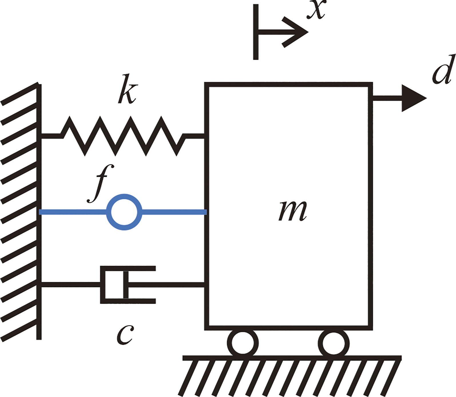
Consider the single degree-of-freedom (SDOF) vibration shown in Figure 1: where, is the displacement of the block; are the mass, damping, and spring constant of the primary system, respectively; and and are the control force and the external disturbance, respectively, that are acting on the mass. The equation of motion for the SDOF system is expressed as
A spring mass damper system.
Considering that the most popular sensor for vibration measurement is an accelerometer, Shin et al.13 proposed the SISO Virtual Tuned Mass Damper (VTMD) control that is expressed by equation (2)
where, are the Laplace transforms of , and
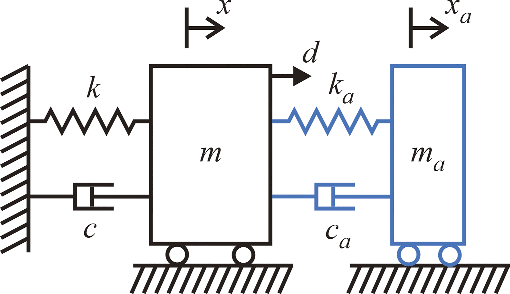
in which, is the gain that can be thought of as the mass of the virtual tuned mass damper, is the damping factor of the VTMD controller that is generally set to 0.3 to provide reasonable control bandwidth, and is the filter frequency of the VTMD controller that is normally tuned to either the driving frequency, or the natural frequency of the primary structure. Shin et al.13 found that the control algorithm expressed by equation (2) exactly emulates the dynamic characteristics of the tuned mass damper shown in Figure 2. The VTMD controller amounts to attaching a passive TMD to the primary mass, as shown in Figure 2.
A spring mass damper system with tuned mass damper.
The advantage of the VTMD controller is that it can accommodate resonant and non-resonant harmonic disturbance, and if it is tuned to the natural frequency, can provide active damping. The closed-loop system incorporating the VTMD controller is naturally stable, because the emulated system with the TMD shown in Figure 2 is mechanically stable.
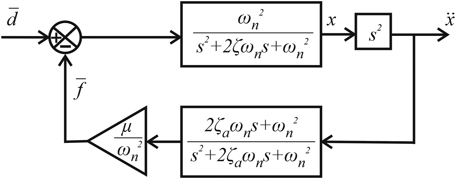
Dividing equation (1) by and introducing , , , , , and , Figure 3 shows the block diagram of the closed-loop system that is obtained.
Block diagram for the closed-loop system by the virtual tuned mass damper controller.
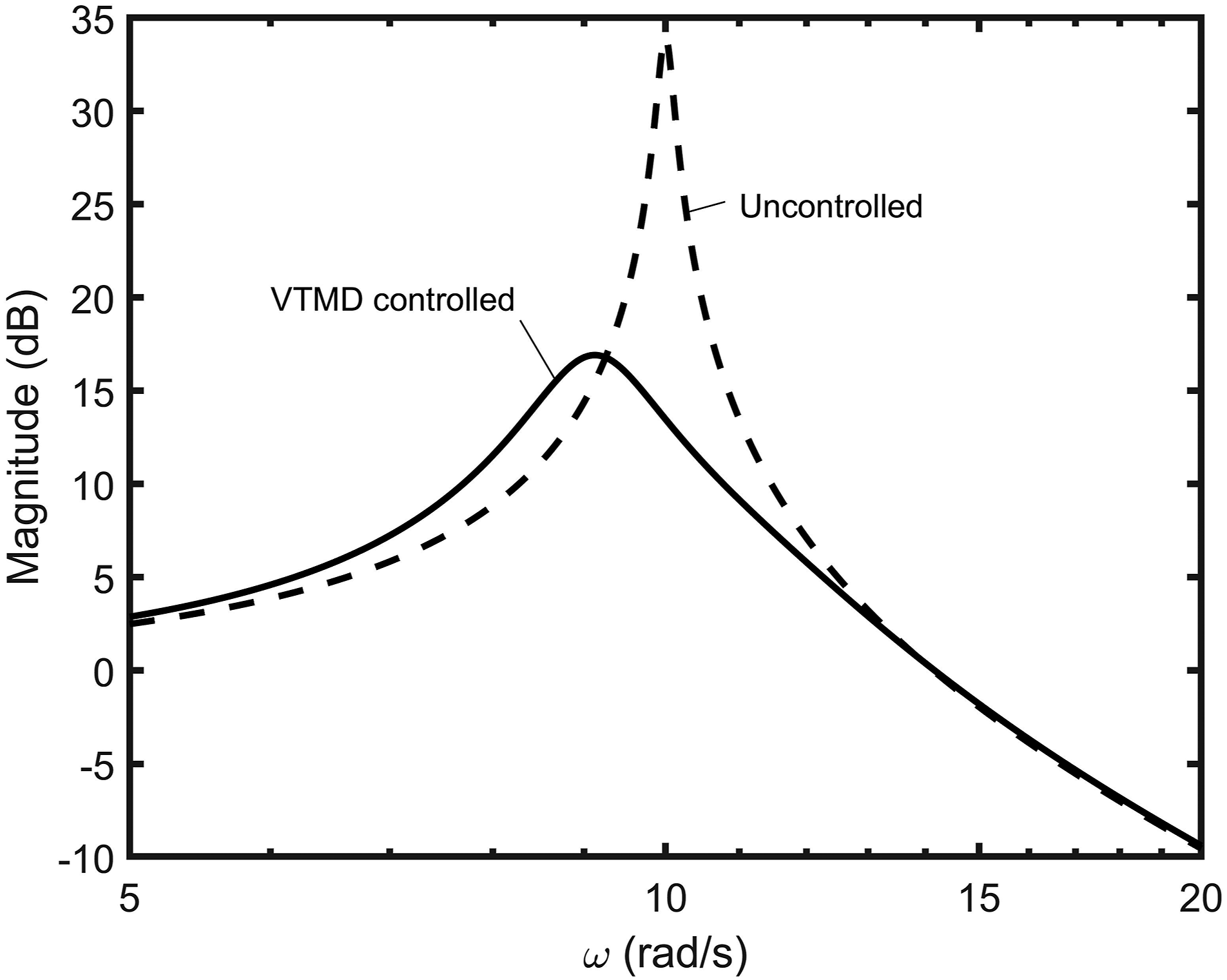
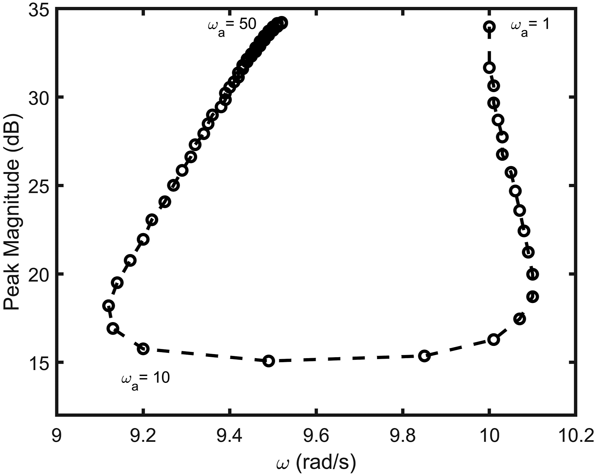
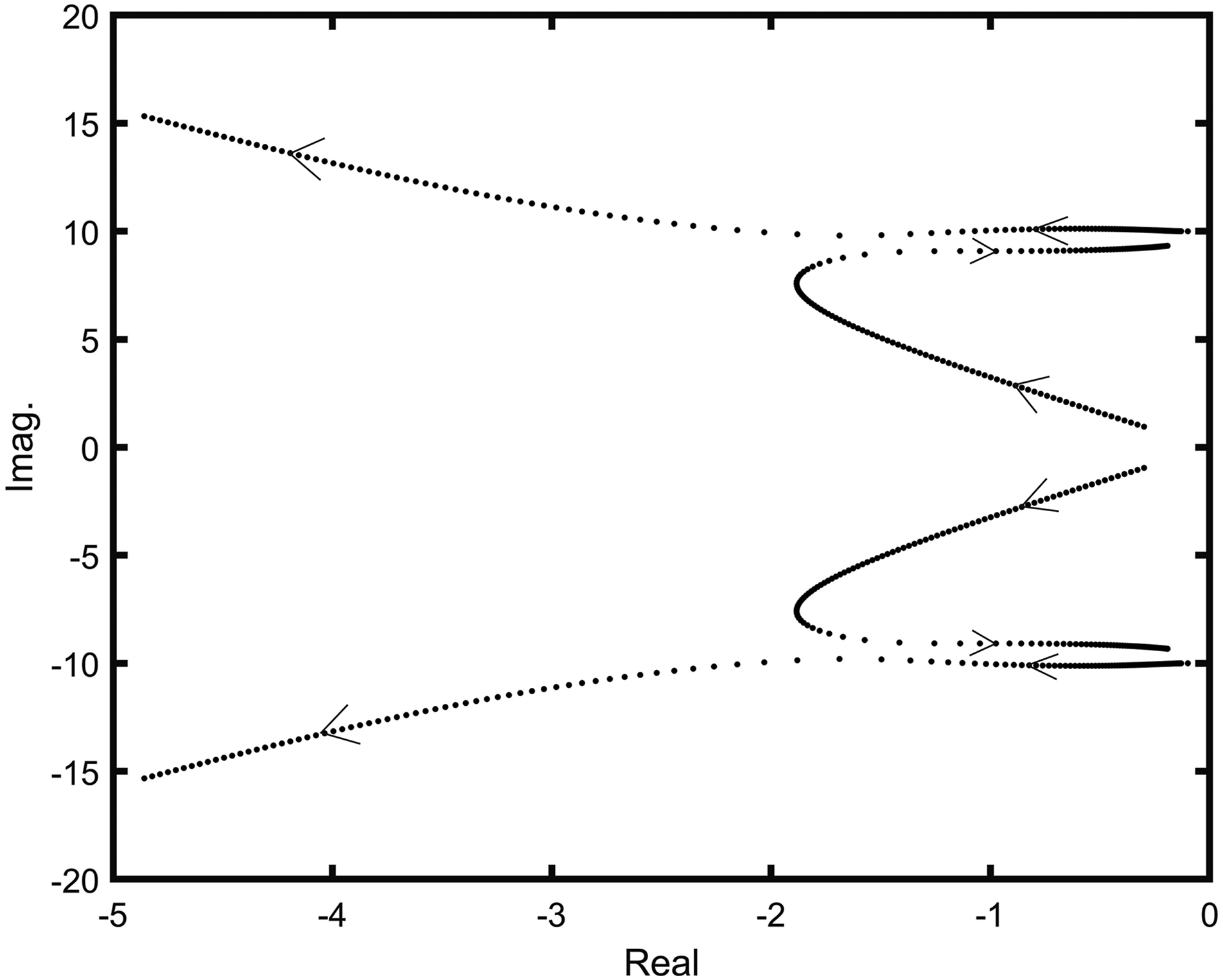
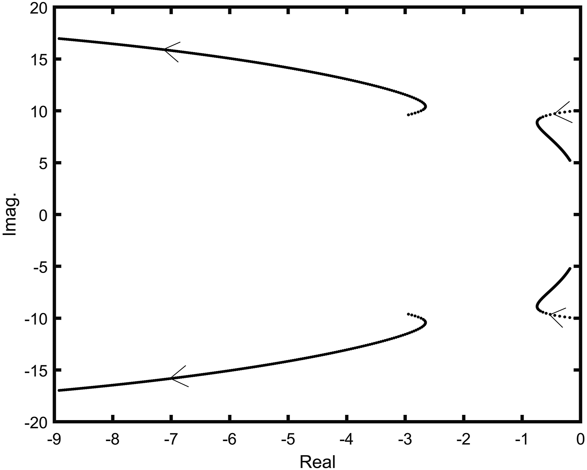
As a numerical example, , , , and were considered. Figure 4 shows the frequency response plots of uncontrolled and controlled cases. The Figure shows that the resonant amplitude decreases by the application of the VTMD controller tuned to the natural frequency of the primary system, and the resonant frequency decreases slightly. Figure 5 shows the peak magnitudes of the frequency response curve versus the filter frequency of the VTMD controller. As can be expected theoretically, as the filter frequency of the VTMD controller approaches the natural frequency of the target structure, the peak amplitude of the frequency response curve becomes minimum. It seems that to get the best performance, the VTMD controller needs to be tuned with the filter frequency slightly smaller than the natural frequency of the target structure. Figure 5 also shows that the application of the VTMD slightly lowers the resonant frequency. If the filter frequency is smaller or larger than the natural frequency of the target structure, then the peak amplitude of the closed-loop system is close to the peak amplitude of the open-loop system, but the closed-loop system remains stable. This confirms that control spillover to lower or higher frequency modes never occurs. Figure 6 shows the root locus of the closed-loop system as the filter frequency changes from (1 to 15) rad/s, which clearly shows that the negative real part of the poles remains on the left half of the complex plane. Figure 7 shows the root locus of the closed-loop system as the gain changes from (0.01 to 1), which shows that the gain of around 0.1 gives the best performance; this means that there exists optimal gain, and as the gain increases, the performance deteriorates.
Frequency response plots.
Peak amplitude versus filter frequency.
Poles of the closed-loop system versus filter frequency.
Poles of the closed-loop system versus gain.
Multi-input multi-output virtual tuned mass damper control
We now turn our attention to the continuous structure discretized by the finite element method or assumed-modes method. In general, the dynamic model can then be expressed as a multi-degree-of-freedom system subjected to the control forces and disturbances
where, are the generalized mass, damping, and stiffness matrices, respectively; is the generalized displacement vector that can be a physical coordinate vector depending on the dynamic modeling method; is the force participation matrix; and is the external force acting on the system consisting of the control force, and the disturbance, , where is the actuator force, and is the disturbance vector, where are the number of displacements used for dynamic modeling, and the number of applied forces, respectively. In this study, we assume that the actuator forces and the disturbance are acting on the same locations. In addition, we assume that the accelerations are measured where the actuator forces are applied, which implies that the actuators and sensors are collocated. Then, we can write
where, is the acceleration vector measured by the accelerometers. The state–space equation can then be constructed using equations (4) and (5)
where, , and
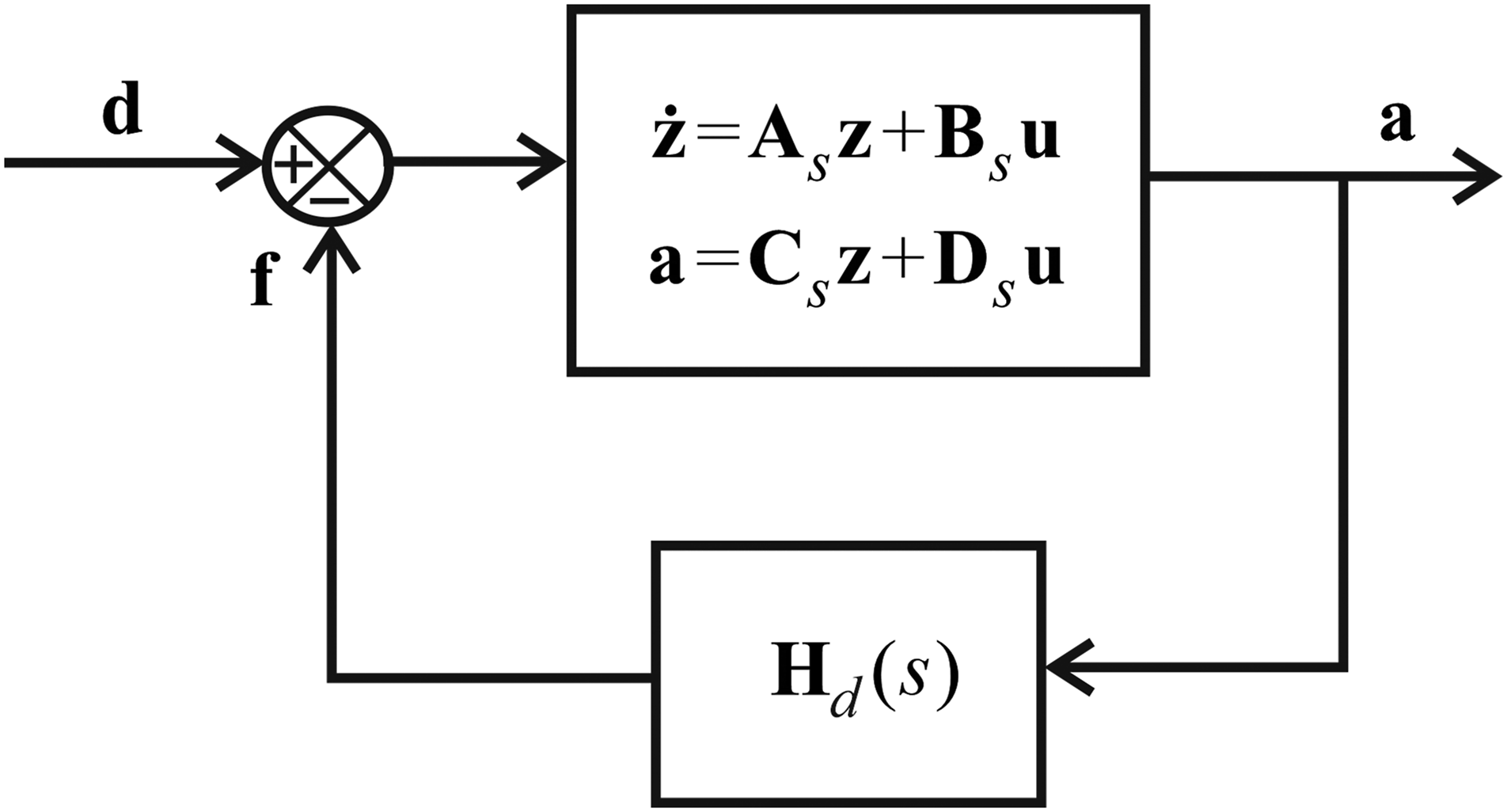
Because the VTMD controller can be thought of the additional spring mass damper system attached to the main structure, the simplest multi-input and multi-output (MIMO) VTMD controller can be designed in such a way that each actuator command is calculated based on the acceleration at the same location. Hence, considering equation (2), the decentralized virtual tuned mass damper (DVTMD) controller can be simply written as
where, are the Laplace transforms of , and is the compensator for each actuator. Considering that the VTMD controller tuned to a certain natural mode does not destabilize other natural modes, the compensator consisting of many VTMD controllers can be designed to suppress target modes at the same time. Hence, the DVTMD controller is proposed in this study that can be expressed as follows
where, is the gain of the jth VTMD control of the ith controller, where the filter frequency of each VTMD controller depends on which natural mode will be tackled at that location. The same damping factor of 0.3 is employed for all VTMD controllers. Equation (10) can be expressed in matrix form as follows
where, and are the Laplace transforms of and , and
The actuator location needs to be carefully chosen to maximize the control efficiency on each natural mode. The design of the DVTMD controller is very simple and straightforward. Figure 8 shows the closed-loop system by the DVTMD controller.
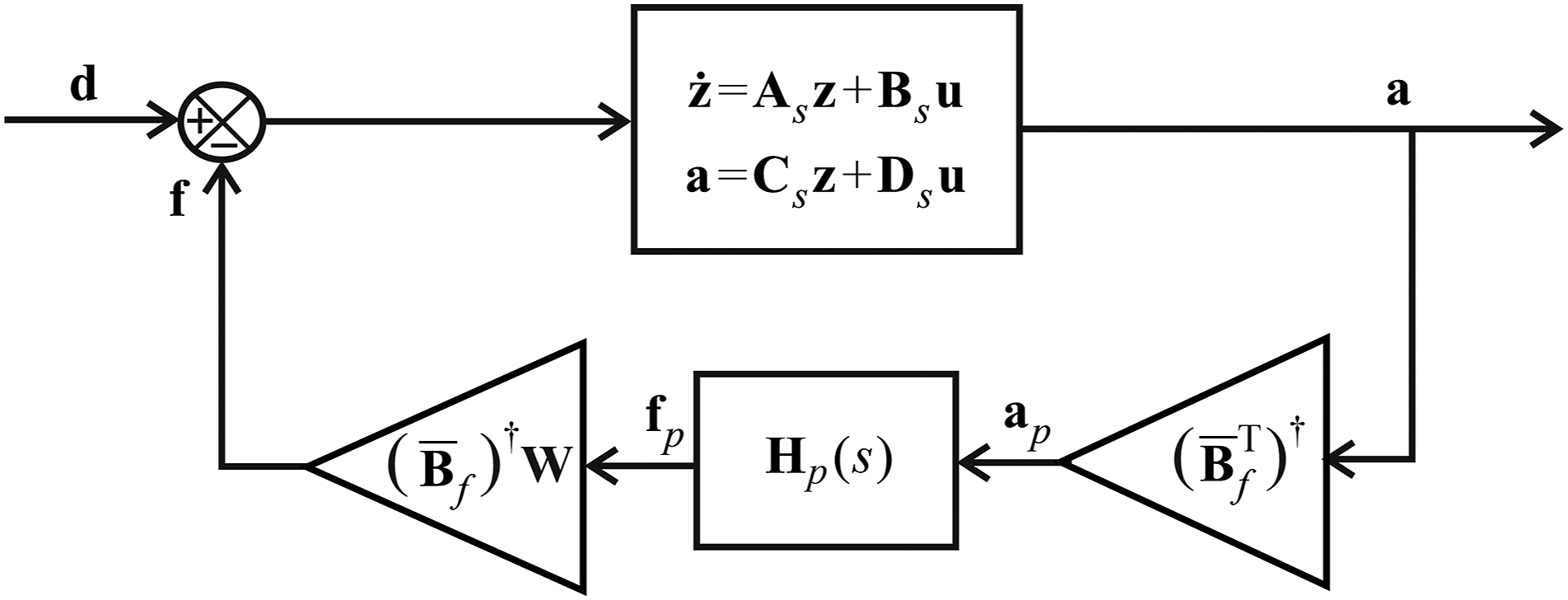
We design the MIMO VTMD controller based on modal coordinates. If we solve the free vibration problem of the undamped system, then we can obtain the eigenvalues and eigenvectors that satisfy the orthonormality conditions
where, are the eigenvector and eigenvalue matrices, and is an identity matrix in which . We also assume modal damping, that is
where, is the damping-factor matrix. The limited number of actuator–sensor pairs cannot control all the natural modes. Assume that only natural modes are to be controlled. Then, the following modal transformation can be used
where, is an matrix that is a reduced subset of the eigenvector matrix, and is the modal coordinate vector to be controlled. Inserting equation (16) into equation (4) and using equations (14) and (15), the following reduced modal equations of motion can be obtained
where, are the subsets of , and
in which
The measurement equation in terms of modal coordinates becomes
where, is the modal acceleration vector. For each modal coordinate to be controlled, equation (17) can be rewritten as
In view of the VTMD control algorithm given by equation (3), the following transfer function of the modal VTMD controller tuned to each natural frequency can be constructed for each modal coordinate independently
where, are the Laplace transforms of , respectively, and is designed to tackle each natural mode, so that it can be expressed as
Equation (23) can be expressed in matrix form as follows
where, and are the Laplace transforms of and , and
If is used as the auxiliary coordinate that represents the displacement of the VTMD, then the following coupled equations of motion can be written for each modal coordinate
In vector matrix form, equations (26) and (27) can be rewritten as
where
Hence, it becomes evident that the closed-loop system is absolutely stable in modal coordinates, which implies that the modal-space VTMD controller can actively suppress target natural modes. However, to apply the modal-space VTMD controller given by equation (22) to real structure, conversion of the measured acceleration into the modal acceleration, calculation of the modal control force based on the modal-space VTMD control algorithm, and conversion of the modal control force into the real force are needed. In doing so, in equations (18) and (20) should be invertible. If the same number of actuators as the number of natural modes to be controlled, that is, , and is invertible, then there will not be a problem. However, the objective is to suppress as many natural modes as possible. Hence, we are dealing with the case that . Fortunately, the control spillover problem of the VTMD controller can be neglected, as shown above. The observer spillover problem also occurs, but it can be neglected, because the modal-space VTMD controller is a kind of band-pass filter that filters the effects of other modes, except for those of the target natural mode. The main problem is how to compute the modal acceleration from the measured acceleration and the actuator force from the modal control force. Because is an rectangular matrix, direct inversion is not possible. One obvious choice is to use the pseudo-inverse. However, the use of the pseudo-inverse when the number of rows is larger than the number of columns results in a badly balanced matrix. In this study, we propose the use of the weighting matrix in addition to the pseudo-inverse. Instead of equation (18), we propose the following equation
where
is the weighting matrix. From equation (30), equation (32) can be derived
where, denotes the pseudo-inverse. Inserting equation (32) into equation (18) yields
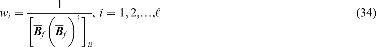
Equation (33) holds if is a square matrix and invertible, and is an identity matrix. This implies that , and the pseudo-inverse becomes the inverse of the matrix. However, if , equation (33) does not hold, because does not result in a diagonal matrix; and in addition, the diagonals of are not unity. We make the diagonals of unity by using the weighting matrix. The weights can be obtained by the following formula
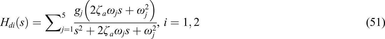
A similar problem occurs when the modal accelerations are calculated using equation (20). Because we are going to estimate more modal accelerations than the number of measured accelerations, the modal accelerations are also calculated by using the pseudo-inverse
It was observed that results in the identity matrix, so the weighting matrix is unnecessary. Using equations (24), (32), and (35), the actuator force vector in terms of acceleration measurements can be expressed as
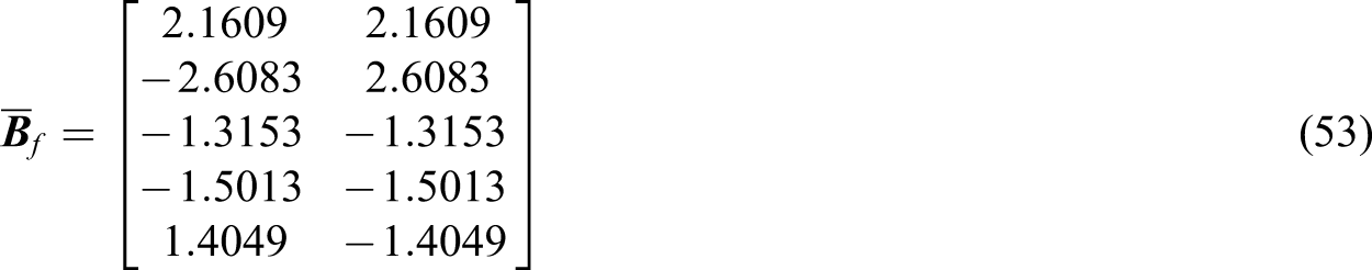
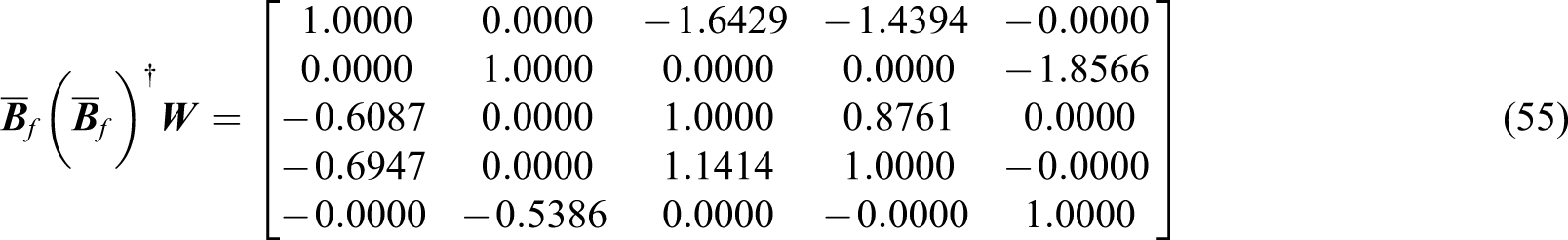
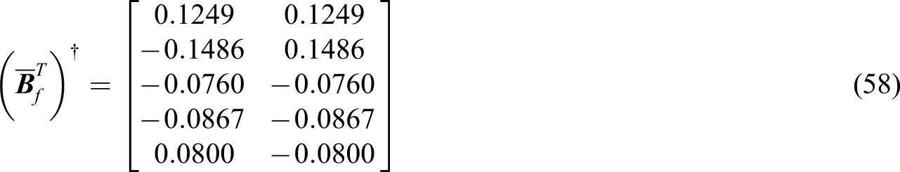
This control algorithm is the CVTMD control based on modal coordinates. Figure 9 shows the closed-loop system for this case. Compared to the decentralized VTMD control algorithm given by equation (12), the CVTMD control algorithm given by equation (36) requires . This implies that an accurate dynamic model should be obtained prior to the control implementation. By comparing Figure 8 with Figure 9, it becomes evident that the application of the DVTMD controller is much simpler than applying the CVTMD controller.
Decentralized multi-input multi-output virtual tuned mass damper controller.
Centralized virtual tuned mass damper controller.
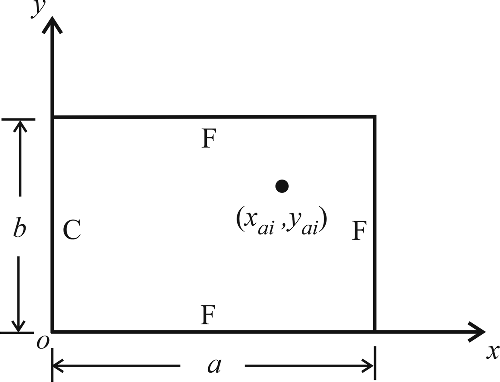
Test structure for the demonstration of active vibration controls
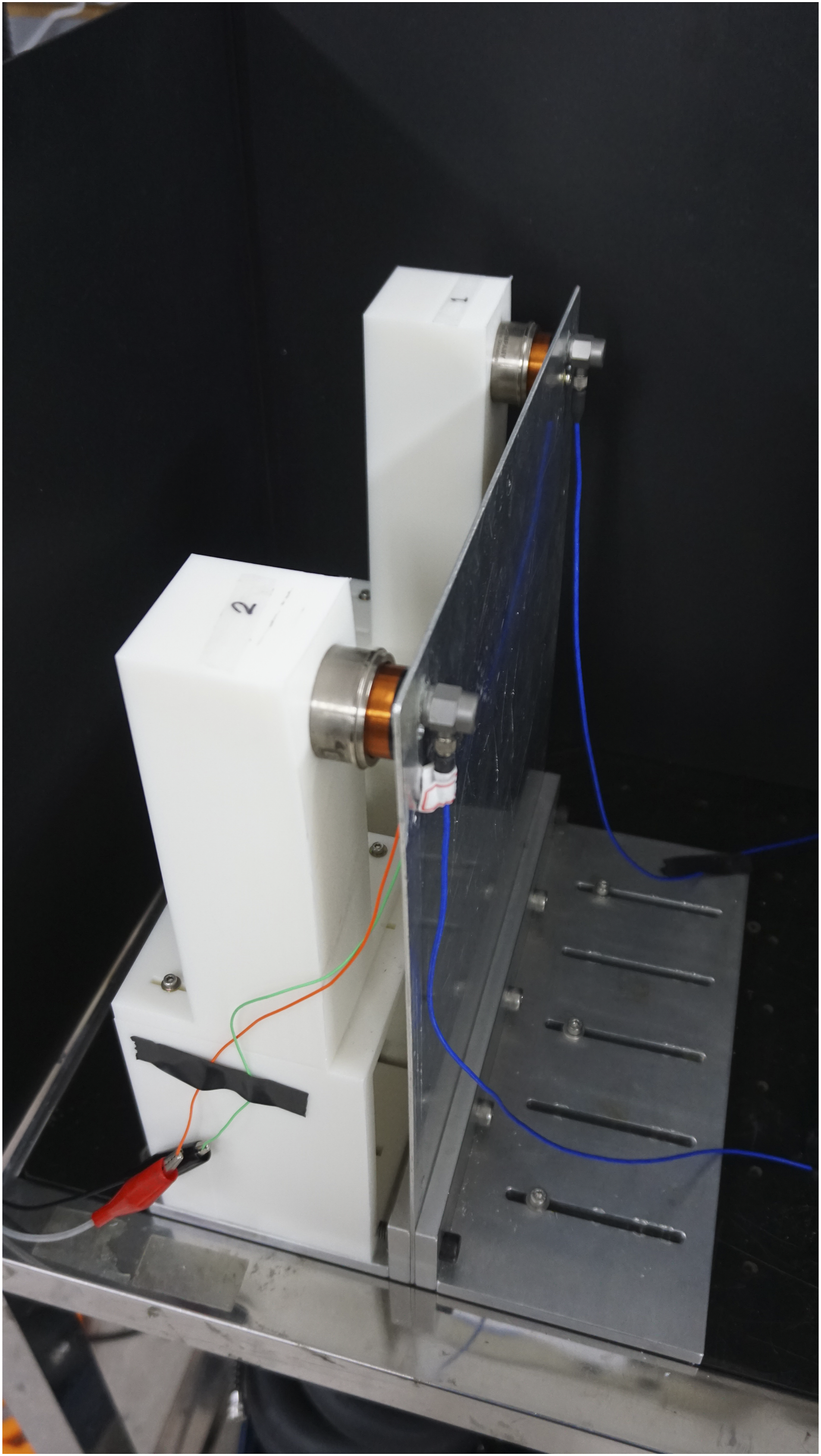
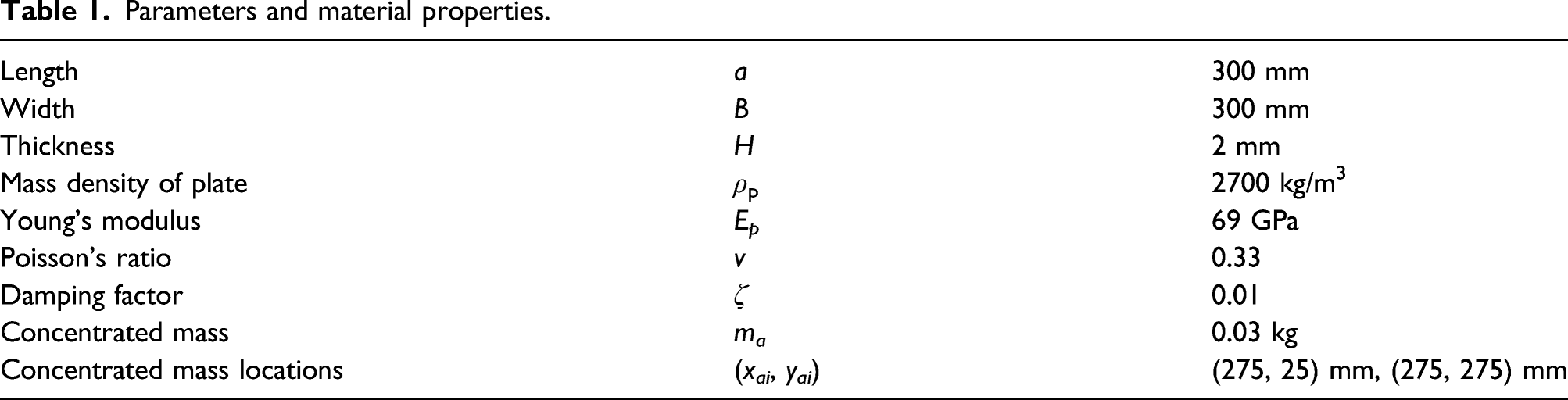
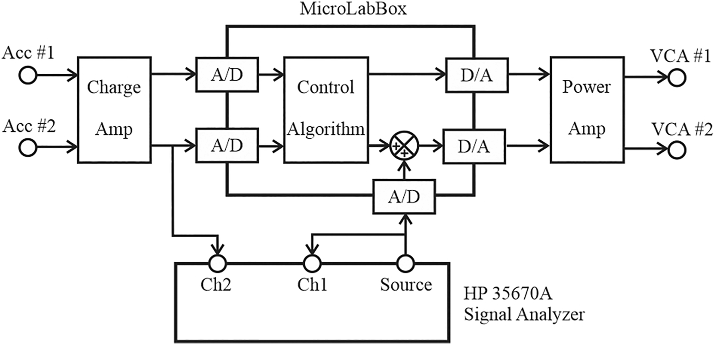
Both DVTMD and CVTMD controls can be applied to any kind of structure whose equations of motion and sensor equations can be represented by equations (4) and (5). Figure 10 shows the test structure that we built to verify the effectiveness of the DVTMD and CVTMD control algorithms. The aluminum plate structure has dimension of 300 mm × 300 mm × 2 mm. Two accelerometers (DYTRAN Model 3055B2, 100 mV/g) and two voice–coil actuators (BEI KIMCO LA14-15A) are mounted at the two corners of the free sides, as shown in Figure 10. Figure 10 shows that the voice–coil actuator and the accelerometer are collocated. Table 1 gives the detailed parameters and material properties for numerical simulations. Damping factor was assumed to be 1% for theoretical study. The accelerometer signals are fed into the analog-to-digital ports of the MicroLabBox of dSPACE, Inc.14 through a charge amplifier (DYTRAN 4103C). MicroLabBox was used to implement both the DVTMD and CVTMD control algorithms digitally. Control algorithms were constructed by using Simulink blocks, and downloaded to MicroLabBox. The accelerometer signals were connected to the A/D port of the MicroLabBox through charge amplifier, and the D/A ports of the MicroLabBox were connected to the voice–coil actuator through a two-channel current amplifier (Eliezer EA120AR2), as shown in Figure 11.
Test structure.
Parameters and material properties.
Length
a
300 mm
Width
B
300 mm
Thickness
H
2 mm
Mass density of plate
ρp
2700 kg/m3
Young’s modulus
Ep
69 GPa
Poisson’s ratio
v
0.33
Damping factor
ζ
0.01
Concentrated mass
ma
0.03 kg
Concentrated mass locations
(xai, yai)
(275, 25) mm, (275, 275) mm
Instruments and wiring diagram.
Dynamic modeling of the cantilever rectangular plate with sensors and actuators
Before experiment, the proposed control algorithms need to be tested numerically. To this end, Figure 12 shows the plate structure of Figure 10 that was modeled. The plate structure is assumed to be a rectangular thin uniform plate with side lengths in the x direction, and in the direction. Figure 12 shows that the boundary conditions are clamped–free–free–free. where, are the collocated actuator and sensor position, respectively. We assumed that the concentrated mass is attached to that position. The concentrated mass consists of the mass of the accelerometer and the mass of the coil-part of the VCA.
Rectangular plate.
Using the assumed-modes method, the deflection of the plate is expressed as15
where, is a matrix consisting of admissible functions, and is an vector consisting of generalized coordinates, for which n is the number of admissible functions used to approximate the deflection. Using the results of Kwak and Han,15 the mass and stiffness matrices in equation (4) for this model can be expressed as
where, is the mass density, h is the thickness, , E is the Young’s modulus, and v is Poisson’s ratio; are the non-dimensionalized mass and stiffness matrices, respectively; is the concentrated mass, and is the number of collated sensors and actuators; and . The damping matrix, in equation (5) was obtained by the modal damping assumption, equation (15). The force participation matrix can be expressed as
Kwak and Han15 showed that the calculation of the mass and stiffness matrices can be further simplified by separating the two-dimensional admissible function into the element-by-element multiplication of the admissible function matrices in each direction, like the separation of variables, as follows
where, indicates the element-by-element multiplication, the non-dimensional variables, , are introduced for each coordinate, and and are matrices, respectively. Then, the non-dimensionalized mass and stiffness matrices can be expressed as15
where, represents the aspect ratio of the plate, and
where, , If admissible functions are used in the X and Y directions, and the combination of these admissible functions are used, a total of admissible functions can be obtained, yielding . If each type of admissible function is considered as and , then the relationship between the sequence of the admissible function introduced in equation (37), and that of the separate admissible functions, can be expressed as15
Therefore, instead of integrating elements in equations (39) and (40), integration and matrix rearrangement will suffice. Kindly refer to the results of Kwak and Han15 for more details.
Since we are dealing with a cantilever rectangular cantilever plate, the eigenfunction of a clamped-free uniform beam is used as the admissible function in the X direction16
The eigenfunction of a free-free uniform beam is used in the Y direction. Hence, for the admissible functions in the Y direction, we have the following
where, λi = 4.730, 7.853, 10.996, 14.137, … , and
The first and the second modes represent the rigid-body modes, and the detailed expressions of matrices given in equation (40) are as described by Kwak and Yang.17
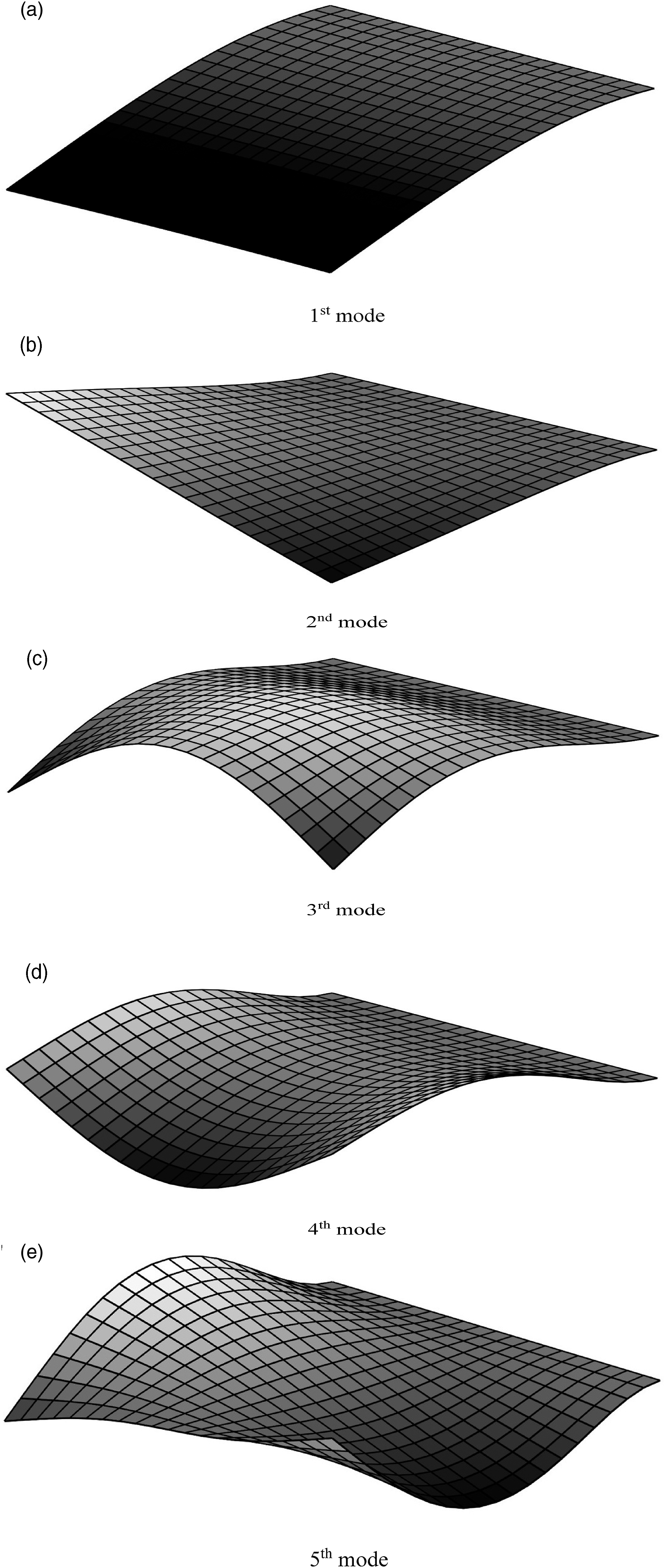
In the numerical calculations, five assumed modes were used in each direction, so that , resulting in the total number of assumed modes, . The lowest five natural modes are to be controlled, so that . The number of actuators is . The same number of sensors were considered. Figure 13 shows the first five natural modes, and its natural frequencies are (16.2, 35.5, 112.0, 127.6, and 150.9) Hz. It can be readily seen that Figures 13(a), (c) and (d) are symmetric modes with respect to the middle line, while Figures 13(b) and (e) are axisymmetric modes.
Considering the five natural modes, the DVTMD controller was designed as equation (51)
where, and are used. The gains were determined numerically by trial and error. Each filter frequency of the VTMD controller was tuned to the natural frequency obtained numerically.
The modal-space VTMD controller of the CVTMD control can be written as
However, the CVTMD controller needs more manipulation to be applied. The force participation matrix given by equation (19) was calculated as follows
Using equation (34), the weighting matrix can be obtained as follows
The weighting matrix results in the following matrix multiplication
As shown above, the diagonals are unity, so that the same amount of modal force can be guaranteed to each modal coordinate. The gain matrix for the CVTMD control was chosen as
Then, the matrices necessary for the CVTMD control were calculated as follows
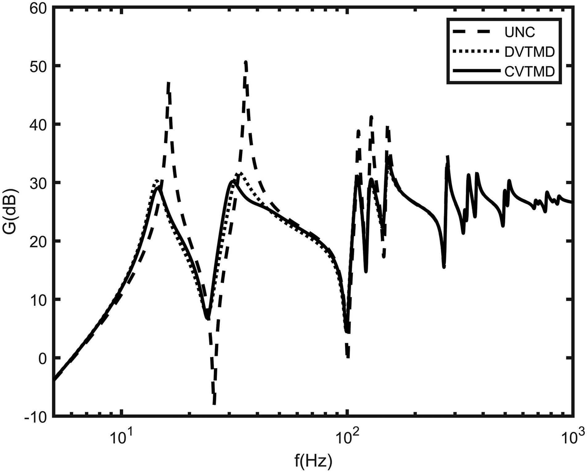
Figure 14 shows the frequency response plots of the uncontrolled, DVTMD controlled, and CVTMD controlled cases. The magnitude of the frequency response curve has the unit of m/s2/N expressed in dB scale. Figure 14 shows that the performances of the DVTMD and CVTMD controls are almost identical. Of course, the gains of each controller were tuned manually. From the viewpoint of control design, the VTMD controller is simpler than the CVTMD controller, so far as the collocated control is considered.
Theoretical frequency response plots of uncontrolled and controlled cases.
Experiments
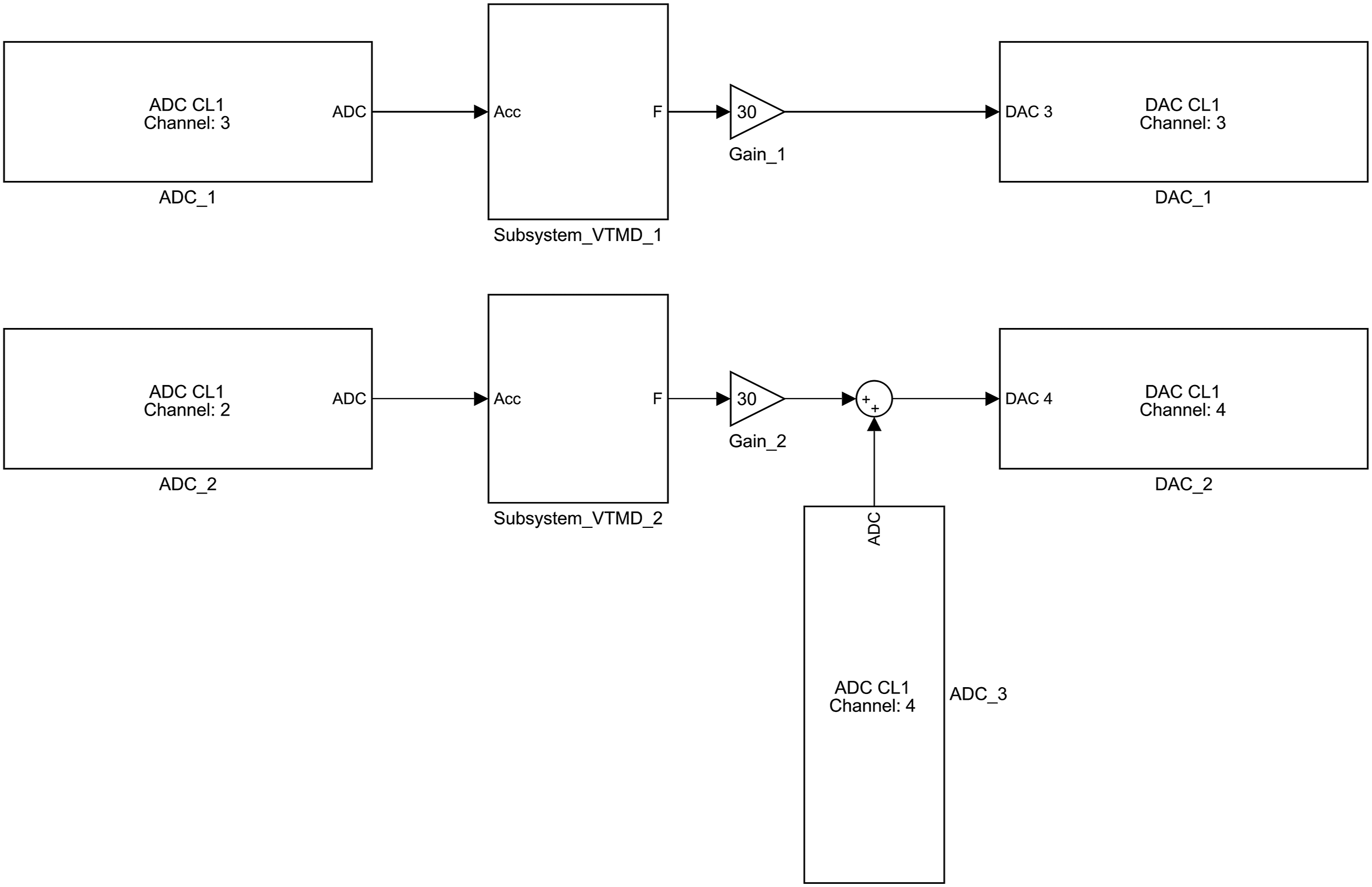
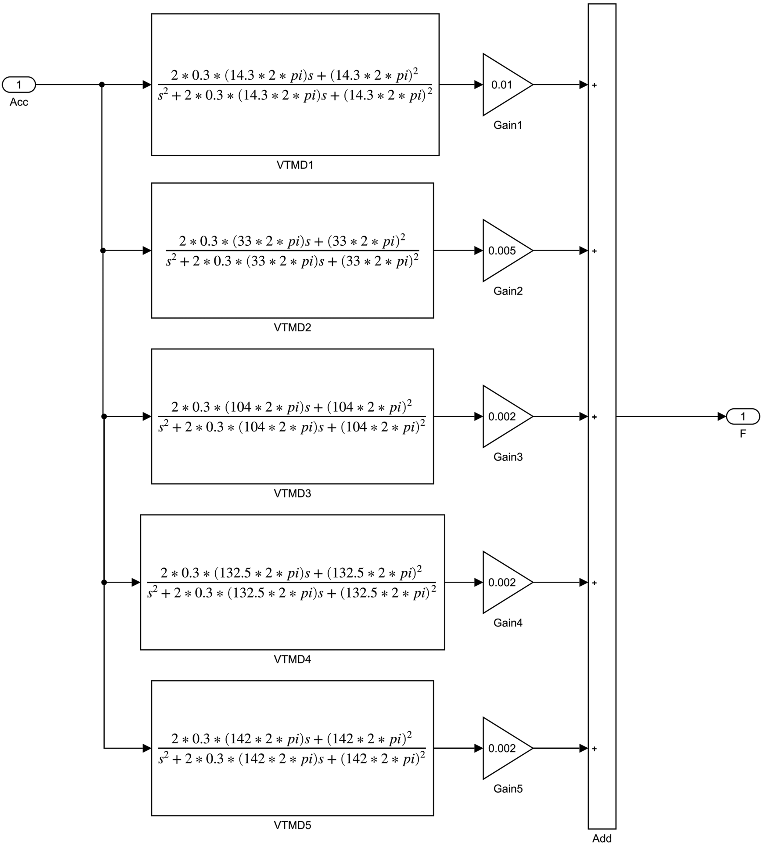
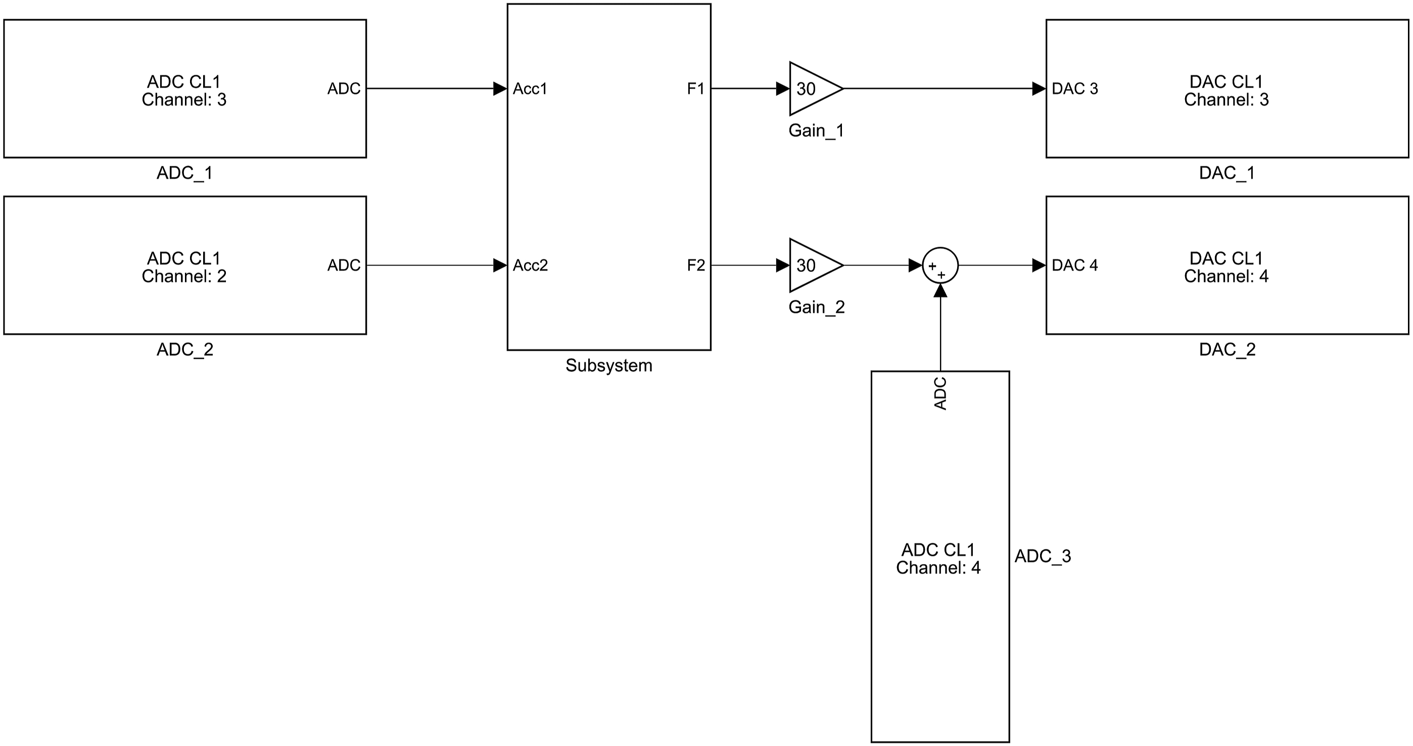
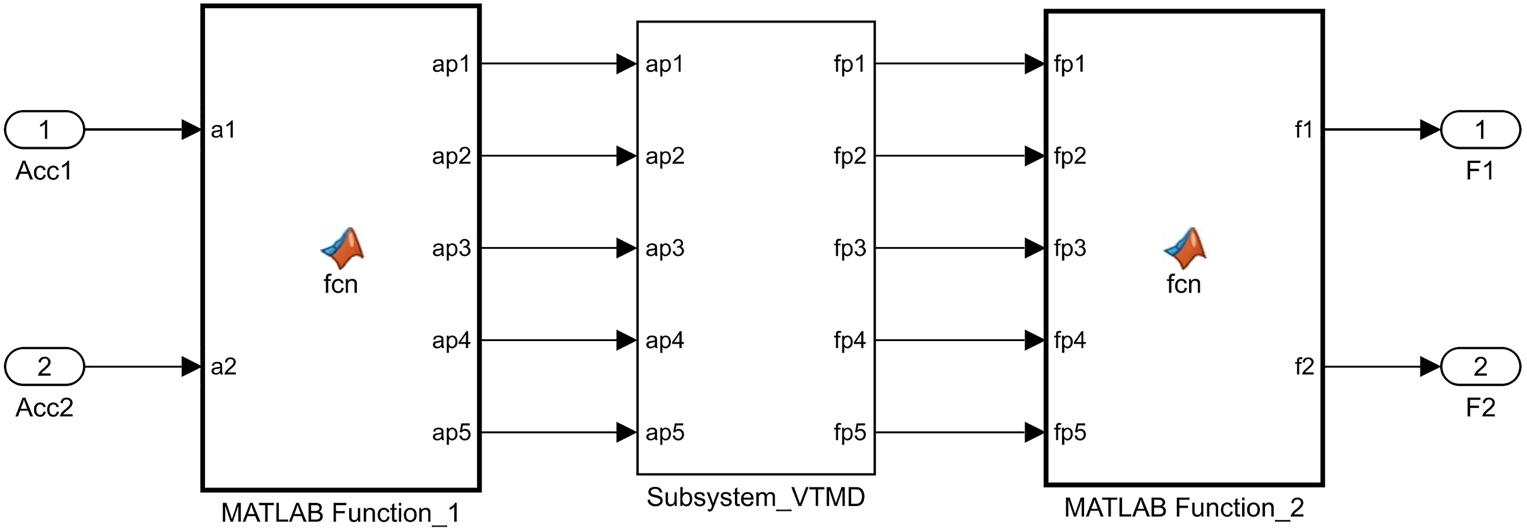
Before designing control, uncontrolled frequency response function was obtained by applying the sine sweep method. From the frequency response function, the experimental natural frequencies were found to be (15.5, 35, 105, 133, and 143) Hz, which are slightly different from the theoretical predictions. The filter frequencies of VTMD controllers were set with experimental natural frequencies. It was found experimentally that the unpowered VCA adds eddy-current damping to the structure, resulting in damping increase in natural modes, unlike the theoretical calculation. Both the DVTMD control and the CVTMD control were constructed by using Simulink blocks. Figure 15 shows the DVTMD controller. It can be seen from Figure 15 that each controller is separated from each other, thus forming the decentralized control. Each DVTMD controller is constructed using Simulink blocks, as shown in Figure 16. The resulting control command is the sum of five VTMD controllers, as also shown in Figure 16. Figure 17 shows the CVTMD control. As the block diagram indicates, the accelerometer signals are fed into the centralized control. Figure 18 shows the modal-space DVTMD controller that was constructed. Figure 19 shows each modal-space VTMD controller. Figures 20 and 21 are MATLAB function blocks that implement the matrix operations given by equations (57) and (58). The excitation signal of the HP signal analyzer was fed into the summation block through the analog-to-digital channel #4 (ADC_3 block) and added to the control signal as shown in Figures 15 and 17 to obtain the closed-loop frequency response to obtain the closed-loop frequency response.
Simulink block diagram for decentralized virtual tuned mass damper control.
Simulink block diagram for each decentralized virtual tuned mass damper control algorithm.
Simulink block diagram for centralized virtual tuned mass damper control.
Simulink subsystem block for centralized virtual tuned mass damper controller.
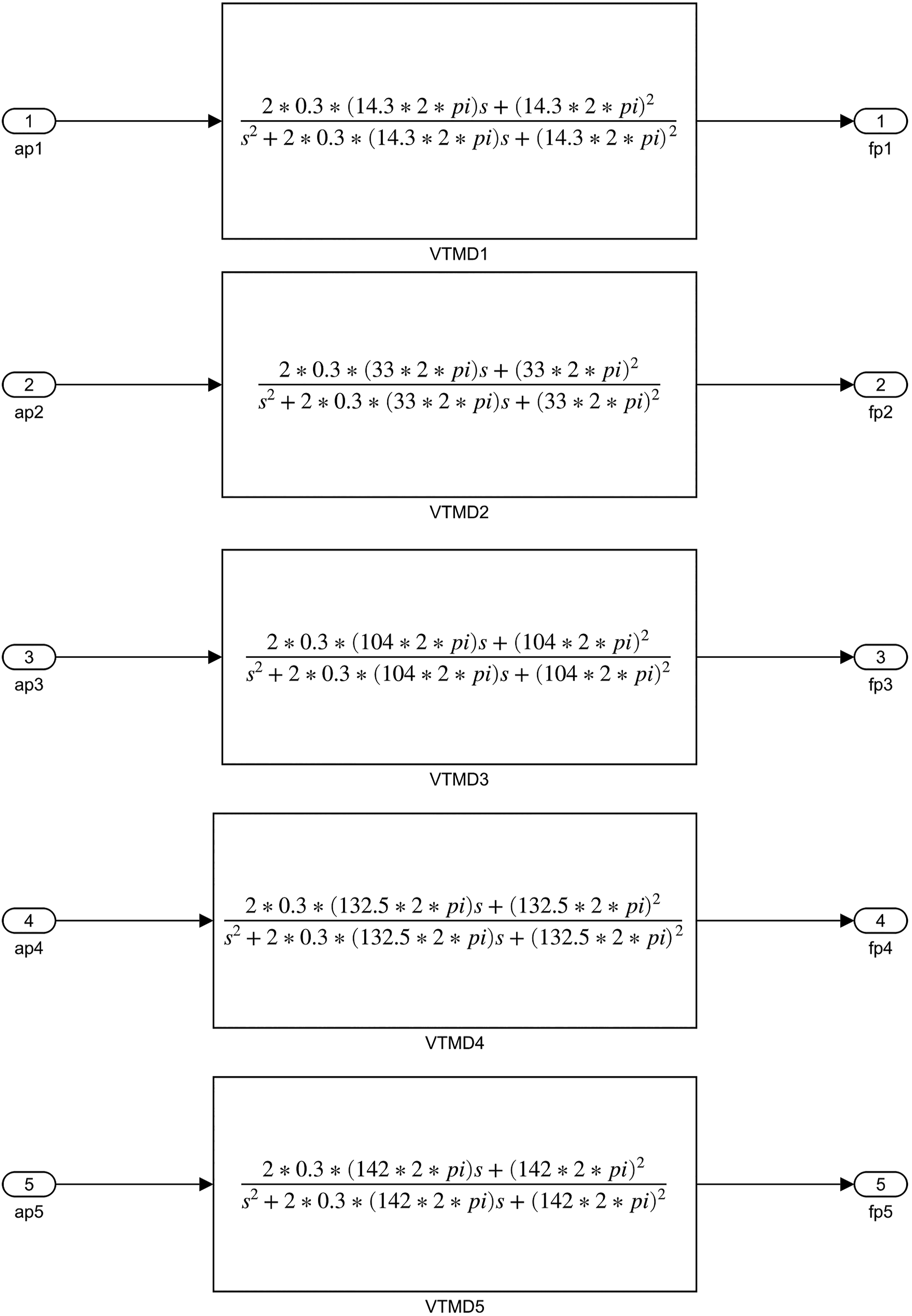
Simulink subsystem VTMD diagram for the modal-space VTMD controller. VTMD: virtual tuned mass damper.
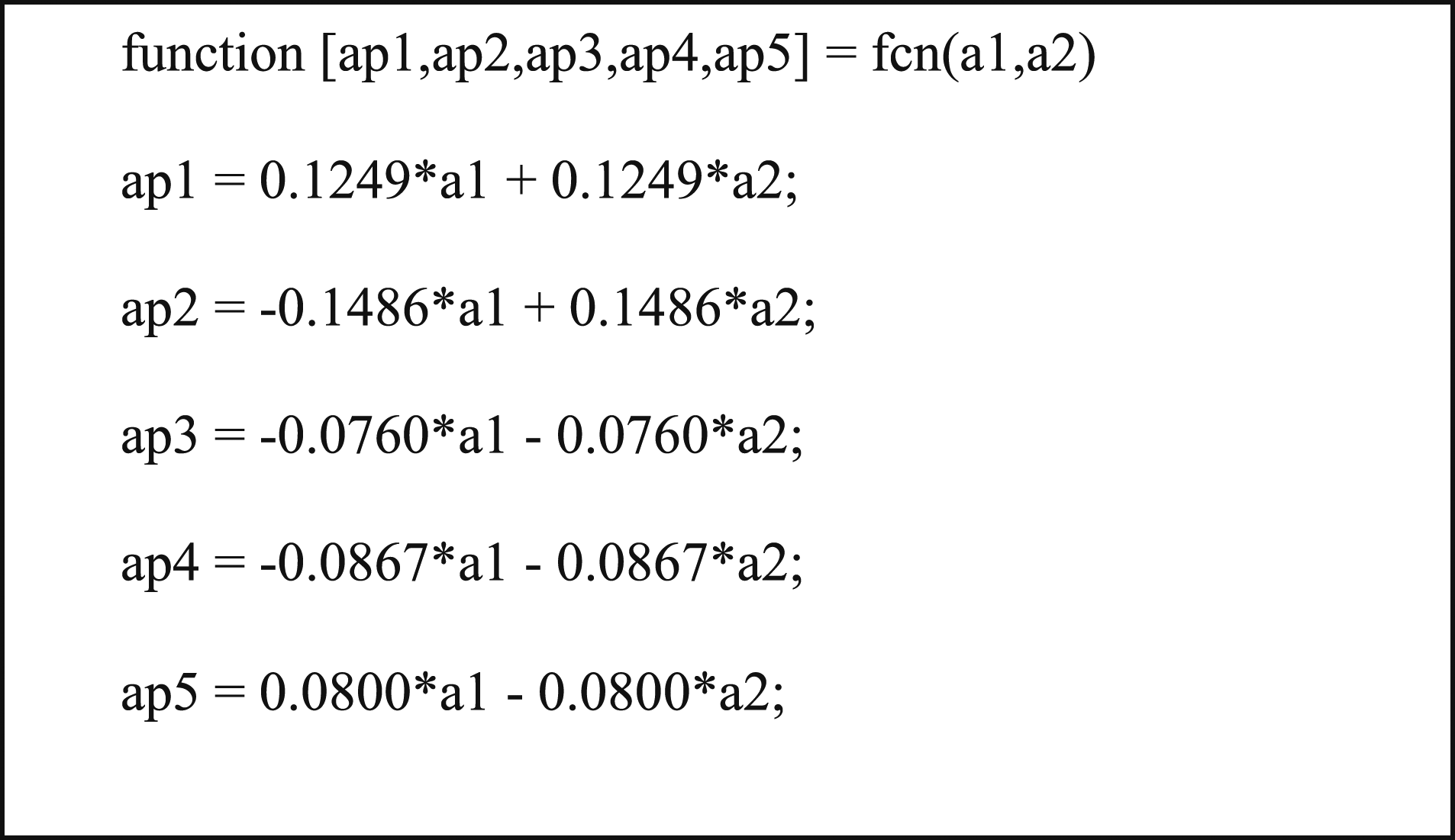
Simulink MATLAB Function_1 block for the transformation of the accelerometer signals to modal coordinates.
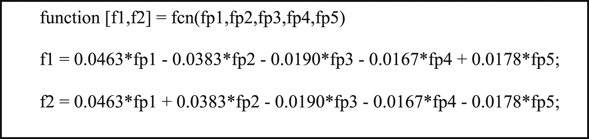
Simulink MATLAB Function_2 block for the transformation of the modal control vector to command signals for VCA actuations.
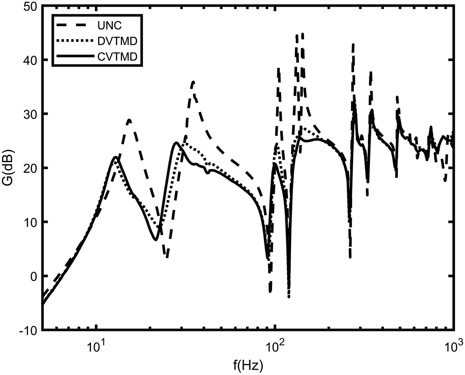
The efficacy of the DVTMD and CVTMD controls applied to the test structure can be seen in Figure 22, which shows the uncontrolled and controlled frequency response curves obtained experimentally. The magnitude of the frequency response curve has the unit V/V, and is expressed in dB scale. The frequency response curve was obtained based on the input voltage to the power amplifier, and the output voltage of the charge amplifier. Note here that the magnitude scale of the frequency response curve is different from that of the theoretical frequency response curve because there are some gains involved in the experiment. The voice–coil actuator converts the current into magnetic force, but the specification does not provide the conversion factor. In addition, the power amplifier converts the command voltage into the current depending on the gain knob, but there is no data on the conversion factor. It was determined in the experimental process that the frequency response curves obtained in this way were kept because the objective of this study is to demonstrate the effectiveness of the proposed control algorithms. It can be readily seen from Figure 22 that both the DVTMD and CVTMD can effectively suppress the vibration of the MDOF system with the limited number of sensors and actuators.
Experimental frequency response plots of uncontrolled and controlled cases.
Discussion and conclusions
In this study, we developed a new active vibration control algorithm that can suppress multiple natural modes with a limited number of sensors and actuators. The new active vibration control algorithm is based on the VTMD control developed in the previous study, which directly uses the accelerometer signal, and produces a control force. The multi-input multi-output decentralized VTMD control and the modal-space centralized VTMD control were developed based on the assumption of the collocation of sensor and actuator.
The proposed DTMD and CTMD controls were verified both theoretically and experimentally. Both the numerical and experimental results show that multiple natural modes can be suppressed successfully by a limited number of sensors and actuators.
The proposed DVTMD control algorithm can be easily designed and implemented, whereas the CVTMD control requires accurate dynamic model and matrix operations. However, the CVTMD control based on the modal-space still has merit, because it can tackle each modal coordinate separately.
The proposed control algorithms can be applied to the active vibration control of structures employing any kind of actuators that can produce force and accelerometers as sensor. The force-type actuators may include the voice–coil actuator, electro-magnetic actuator, pneumatic and hydraulic actuators, so that the proposed control algorithm can be easily used to suppress vibration of automobiles, airplanes, ships, railway vehicles, and semi-conductor manufacturing devices.
Footnotes
Declaration of conflicting interests
The author(s) declared no potential conflicts of interest with respect to the research, authorship, and/or publication of this article.
Funding
The author(s) disclosed receipt of the following financial support for the research, authorship, and/or publication of this article: This work was supported by the Technology Innovation Program (20011159, Development of 3-axis active vibration control system capable of controlling vibration below 1 Hz) funded By the Ministry of Trade, Industry & Energy (MOTIE, Korea).
ORCID iDs
Soo-Min Kim
Moon K Kwak
Ki-Seok Song
References
1.
KwakMK. Dynamic modeling and active vibration control of structures. 1st ed.Dordrecht: Springer, 2021.
2.
DykeSJSpencerBFJrQuastP, et al.Implementation of an active mass driver using acceleration feedback control. Computer‐Aided Civil Infrastructure Eng1996; 11: 305–323.
3.
SimELeeSW. Active vibration control of flexible structures with acceleration feedback. J Guidance, Control Dyn1993; 16: 413–415.
4.
YangDHShinJHLeeHW, et al.Active vibration control of structure by active mass damper and multi-modal negative acceleration feedback control algorithm. J Sound Vibration2017; 392: 18–30.
5.
FansonJLCaugheyTK. Positive position feedback control for large space structures. AIAA Journal1990; 28: 717–724.
6.
AthansMFalbPL. Optimal control: An introduction to the theory and its applications. 1st ed.New York: Dover, 2007.
McNamaraRJ. Tuned mass dampers for buildings. J Struct Division1977; 103: 1785–1798.
9.
ShinJHKwakMKKimSM, et al.Vibration control of multi-story building structure by hybrid control using tuned liquid damper and active mass damper. J Mech Sci Technology2020; 34: 5005–5015.
10.
WuSTShaoYJ. Adaptive vibration control using a virtual-vibration-absorber controller. J Sound Vibration2007; 305: 891–903.
ZhouDFHansenCHLiJ. Suppression of maglev vehicle–girder self-excited vibration using a virtual tuned mass damper. J Sound Vibration2011; 330: 883–901.
13.
ShinJHLeeJHYouWH, et al.Vibration suppression of railway vehicles using a magneto-rheological fluid damper and semi-active virtual tuned mass damper control. Noise Control Eng J2019; 67: 493–507.
KwakMKHanS. Free vibration analysis of rectangular plate with a hole by means of independent coordinate coupling method. J Sound Vibration2007; 306: 12–30.
16.
BlevinsRD. Formulas for Natural Frequency and Mode Shape. Florida: Krieger Publishing Company, 2001.
17.
KwakMKYangDH. Free vibration analysis of cantilever plate partially submerged into a fluid. J Fluids Structures2013; 40: 25–41.