
Abstract
To effectively and efficiently control vibrations in steel bridge decks, the flexural wave band gap and vibration attenuation mechanism are studied. The band structures and displacement fields of the eigenmodes at the band gap edges of infinite periodic U-rib stiffened plates are calculated. The calculation method is combining the finite element method with Bloch periodic boundary conditions. A scaled specimen test of a finite periodic U-rib stiffened plate is used to validate the numerical results. A comparison of results confirms that introducing the U-rib allows the periodic U-rib stiffened plates to yield several flexural wave band gaps. In the band gaps, flexural wave propagation is stopped and clear flexural vibration suppression is achieved. Furthermore, the effects of geometric parameters and structural schemes on the flexural wave band gaps are analyzed in detail. Finally, by analyzing a specific case, it is demonstrated that the flexural wave band gaps and vibration attenuation properties can be controlled. This provides a new approach to vibration and noise control in steel bridges.
Introduction
Bridge structural vibrations and noise caused by high-speed movement of heavy-duty train loads are becoming increasingly problematic.1–3 Bridge vibrations not only reduce rail transit serviceability and reliability, but also have significant adverse influences on public comfort. Hence, it is important to effectively and efficiently control vibration and provide low-noise bridge designs.
Traditional strategies for controlling vibration and noise in steel bridges have been investigated and summarized by Haddy, 4 Li et al., 5 Lei, 6 and Liu et al. 7 They can generally be divided into two classes: (I) reduce vibration energy input to the bridge and (II) eliminate vibration transmission within the bridge.
In type-I approaches, the track structure is critical to energy reduction because vibration energy is transferred to the bridge via the track structure. The main rail vibration reduction measures are damping rails and rail vibration absorbers.8,9 In under-rail isolation approach, the elastic fasteners investigated by Luo et al. 10 are typically used to reduce the vibration energy of the under-rail structure in order to reduce bridge vibration noise. However, Cui et al. 11 have identified some new problems caused by elastic fasteners, for example, serious abnormal rail wear. The main vibration reduction strategies used under sleepers include ballasted cushion, elastic sleeper, trapezoidal sleeper, and floating slab. 12 These approaches have been proved to be more effective than using elastic fasteners.
In type-II approaches, absorbing bridge vibration energy is the most common and effective method of reducing bridge vibrations. Typically, the tuned mass damper is used for seismic response control in bridges, and its excellent effects have been proved by Matin et al. 13 and Elias et al. 14 Whereas, the effectiveness of tuned mass dampers to control bridge noise has not been verified. To control vibration and noise, some other substantial damping improvement strategies were proposed by Larbi 15 and Meyer and Seifried. 16 However, it is difficult to ensure close adhesion between damping layers and bridge components under long-term train-induced vibration loads. Moreover, although existing approaches can be used to control bridge vibration and noise to a reasonable extent, 17 they have disadvantages that include material aging characteristics, poor manual adjustment, and narrow effective frequency bands.
In addition to the traditional vibration control methods listed above, extensive studies have been performed to explore the elastic wave propagation and attenuation characteristics of periodic structures. 18 However, these strategies are rarely utilized in bridge engineering. Khelif et al. 19 studied drilled-hole periodic plates with piezoelectric inclusions placed periodically in an isotropic matrix material. The plane-wave expansion method was used to study flexural wave propagation characteristics in two-dimensional (2D) periodic thin plates. 20 The above studies show that the band gap frequency range is quite high in these types of periodic plates. Thus, this limits their applications.
The local resonance mechanism can easily generate lower band gaps. Xiao et al. 21 researched propagation of Lamb waves in 2D locally resonant periodic plates made from either soft materials or a heavy core coated with soft materials and embedded in a periodic matrix form. Li et al.22,23 investigated low-frequency broadband elastic wave attenuation and vibration suppression in periodic plates. A series of periodic plates with similar structures were also investigated in later studies. Zhou et al. 24 established the dynamic equation for one-dimensional periodically stiffened thin plates. They found that the stiffened periodic plate produces band gaps in frequency ranges that can be enlarged by changing the structural parameters. Ampatzidis et al. 25 examined the band characteristics of composite one-dimensional periodic plates with manufactured stiffener elements using the finite element method (FEM). Zhou et al. 26 also used a semi-analytical approach based on the FEM and space harmonic methods to explore optimal strategies that involved the band gaps of systems made with periodic stiffener plates. These studies have provided new insights into vibration and noise control of plate-type structures, which is one of the motivations of this study.
Although the flexural wave band gaps (FWBGs) of periodic plate structures have been studied in various fields, they have been investigated little in bridge engineering. Bridge decks that are periodically stiffened with U-ribs are commonly used in steel bridges, as shown in the left part of Figure 1. In this paper, for the first time, the FWBGs and vibration transmission characteristics of steel bridge decks that have been stiffened periodically with U-ribs are investigated numerically and a scaled experiment is performed to validate the reliability of the numerical method. Then, the FWBG formation mechanism is explained via the eigenmode displacement field. Finally, the influences of some geometric parameters and bridge deck schemes, including the baseplate and U-rib thicknesses, the U-rib spacing, and the U-rib size on the FWBGs, are discussed. A specific case is given as an engineering application demonstration. A typical steel bridge deck and its schematic of a periodic U-rib stiffened plate.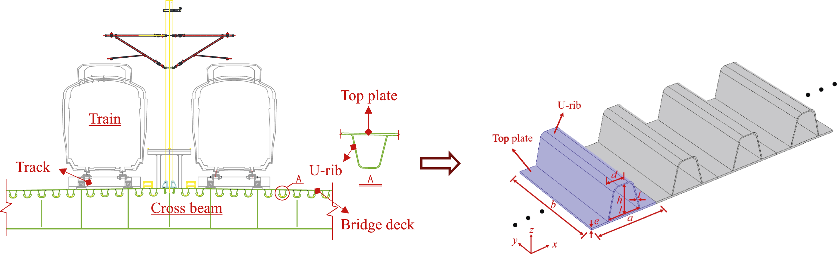
Model and calculation method
Description of a periodic U-rib stiffened plate
The right part of Figure 1 shows the outline of a periodic U-rib stiffened plate (PUSP) that is fabricated by welding the local resonator (i.e., U-rib) onto the baseplate (i.e., top plate) surface. The unit cell of the PUSP is highlighted in blue and is repeated infinitely along the x-direction, that is, the lateral direction of the bridge. Note that this paper deals with vibration attenuation along the lateral direction of the bridge.
The dimensions of the unit cell are given in Figure 1, where a is the lattice constant in the x-direction, b denotes the finite length in the y-direction (i.e., longitudinal direction of the bridge), e and t are the thicknesses of the top plate and U-rib, respectively, and l, d, and h represent the upper width, lower width, and height of the U-rib, respectively. The PUSPs are made from steel with a mass density of 7850 kg/m3, Poisson’s ratio of 0.3, and Young’s modulus of 210 GPa. The damping effect is neglected due to its low damping characteristics. The original PUSP parameters are listed as follows: b = 1000 mm, e = 16 mm, a = 600 mm, l = 300 mm, d = 180 mm, h = 280 mm, and t = 8 mm.
Finite element method analysis combined with Bloch theory
To investigate the PUSP FWBGs, the FEM was combined with Bloch theory to determine the dispersion relations and transmission spectra.18,25,26 For a unit cell of the U-rib stiffened plate as shown in Figure 2(a), the vibration equation based on FEM is expressed as Numerical calculation model: (a) a unit cell with a Bloch boundary condition and (b) calculation of the transmission spectrum.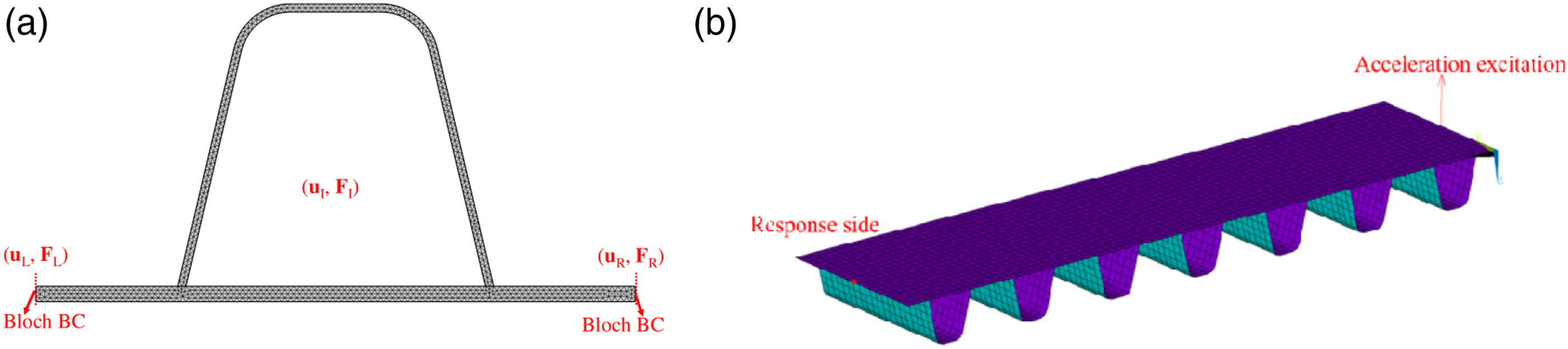


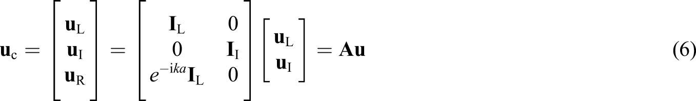
According to the Bloch theorem, the boundary conditions in the unit cell are given by


Substitute equation (6) into equation (1), and multiply both sides by

Expanding the right side of equation (7) and combining it with equation (5), we have

Herein we consider the free wave propagation, and thus

With regard to the calculation of PUSP transmission spectra, a finite structure composed of several unit cells along the x-direction is shown in Figure 2(b). Harmonic acceleration excitation along the z-direction is applied to the top plate surface at the right side, and propagation of flexural waves occurs along the x-direction. Thus, the average displacement response on the left side is obtained. The transmission spectrum is defined as follows

The band gap mechanism
Figure 3(a) shows the band structure of the bare top plate without a U-rib. It has two energy bands that, starting at a frequency of zero, correspond to the longitudinal wave (L) and flexural wave (B
x
) modes, respectively. In other words, the band structure consists of two basic modes (i.e., L0 and Bx0 modes) and their frequency multiplier modes (i.e., L
n
and B
xn
modes, where n = 1, 2, ...). Band structure diagrams: (a) the bare top plate without a U-rib and (b) the U-rib stiffened plate.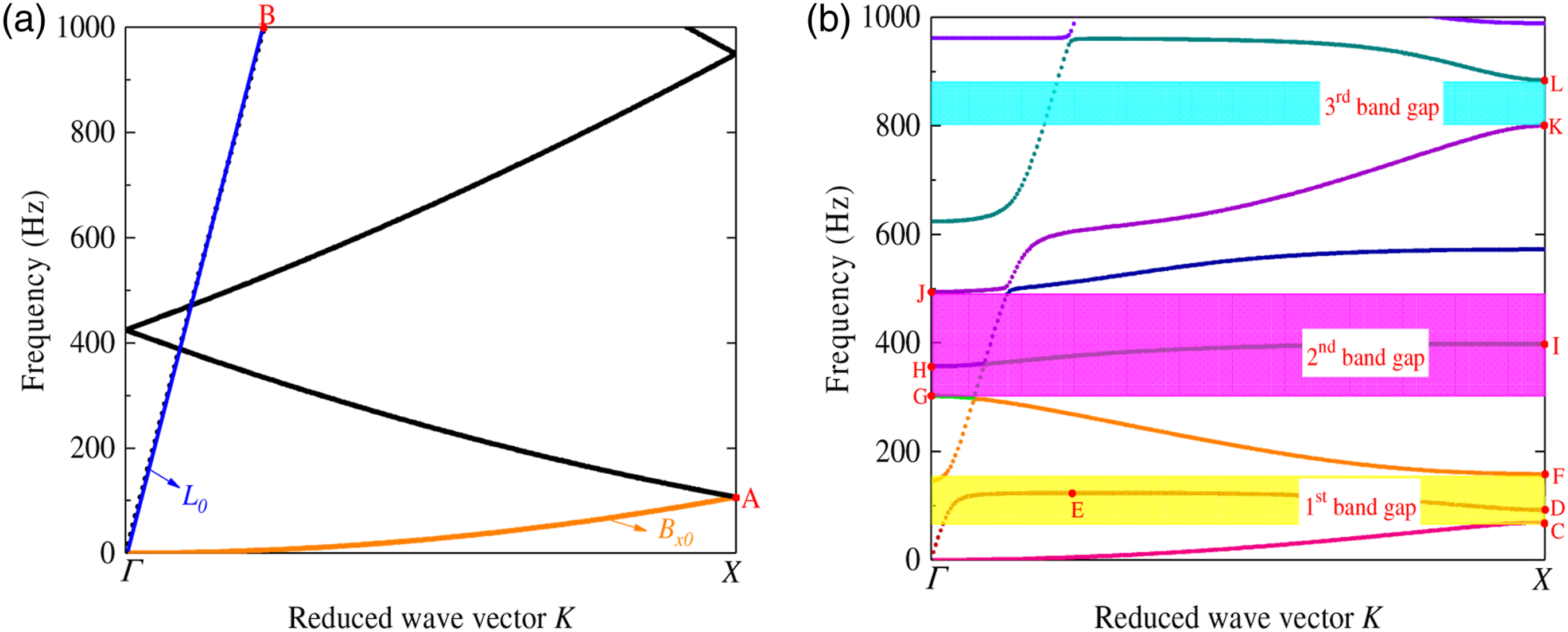
Figure 3(b) shows the PUSP band structure. Since several straight bands are present, different elastic wave field directions and sizes correspond to the same vibration mode due to local resonance. Since noise radiated from the bridge deck plate typically originates from flexural vibrations, attention is paid to flexural wave propagation properties and corresponding vibration band gaps. The PUSP has three kinds of flexural wave band gaps in the frequency range from 0 to 1000 Hz. These are 69–158 Hz, 302–494 Hz, and 800–884 Hz, as shown in Figure 3(b).
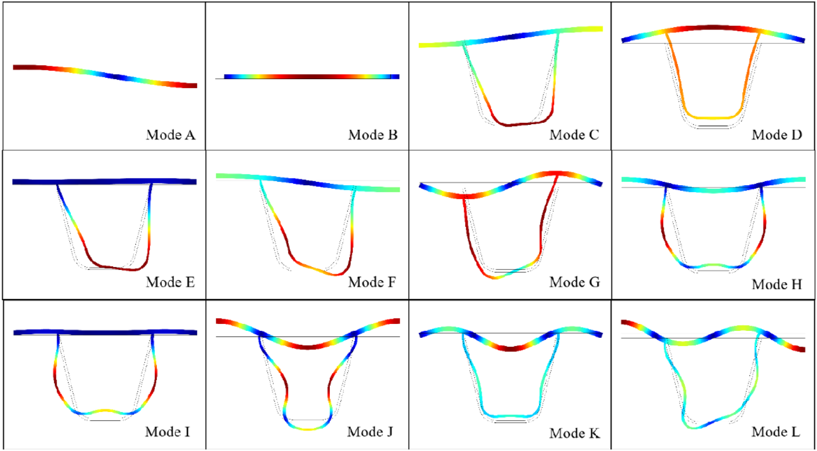
To investigate the PUSP FWBG formation mechanism intuitively, the unit cell displacement fields at the specific wave vectors labeled in Figures 3(a) and (b) are shown in Figure 4. From Figure 4, modes A and B are the eigenmode displacement fields of the bare top plate without a U-rib. Modes C through L correspond to the lower and upper edge eigenmodes of the first, second, and third flexural wave band gaps. They are described as follows: 1. Modes C, D, E, and F represent the first-order vibration modes of bending wave B
x
in the baseplate. The baseplate and U-rib exhibit same-phase or reverse-phase vibration about the structural centerline. Mode E is the resonance coupling mode of bending wave B
x
and the U-rib. In this mode, the baseplate is almost stationary and bending wave B
x
cannot propagate in the baseplate, while the U-rib vibrates. This result indicates that the effect of flexural wave on the top plate is weakened or offset by the effect of local resonance inside the U-ribs. This produces the so-called flat band structure. Therefore, the first band gap mechanism is the absence of a first-order vibration mode of bending wave B
x
in the baseplate. 2. Similarly, modes G, H, I, and J represent the second-order vibration modes of bending wave B
x
in the baseplate. The vibration modes of the baseplate and U-rib are the same as that in the first band gap. The second band gap forms because there is no second-order vibration mode of bending wave B
x
in the baseplate. 3. Modes K and L represent the third-order vibration modes of bending wave B
x
in the baseplate. The third band gap forms due to the lack of a third-order vibration mode of bending wave B
x
in the baseplate. Eigenmode displacement fields of modes A–L identified in Figure 3(a) and (b).
In conclusion, the PUSP band gap forms mainly due to a lack of bending vibration modes along the x-direction (B xn mode, where n = 1, 2, …) due to introduction of the U-rib. Specifically, when certain frequency is close to the natural frequency of the resonant element (i.e., the U-ribs), the local resonance mode of the element structure will be excited, and the flexural wave propagated in the baseplate will have a strong coupling effect with the local resonance mode of the structure. During this process, the energy will be exchanged to the resonant element and become localized, and the flexural wave cannot continue to propagate forward.
The unit cell with infinite periodicity is an ideal system that is used to analyze band gap characteristics, whereas the actual bridge structures used in civil engineering are finite structures. In an attempt to validate FWBG accuracy and attenuation in an infinite PUSP, the transmission spectrum of a system with seven unit cells along the x-direction and 1 m of length along the y-direction of the PUSP is processed as shown in Figure 5. By conducting unit cell number tests, it was found that the seven unit cells yielded similar results to further increased unit cell number but with much lower computational cost. Transmission spectra of flexural waves in the periodic U-rib stiffened plate.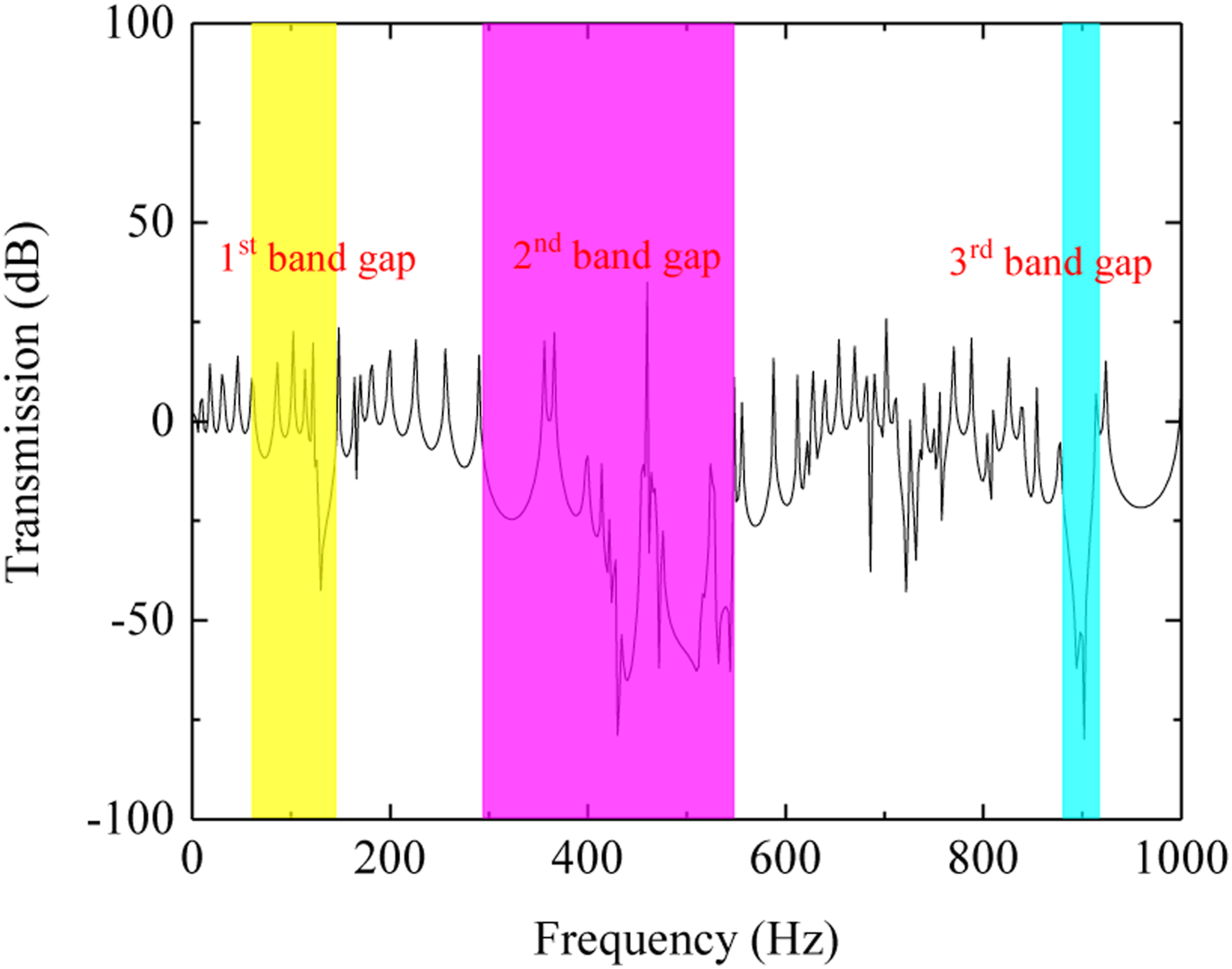
As shown in Figure 5, there are three attenuation zones between 0 and 1000 Hz. The location and width of the attenuated area in the transmission spectrum approximately match the FWBGs from the dispersion relation. It is noted that the second band gap has the largest attenuation effect of the three band gaps and that the frequencies that correspond to this band gap are within the dominant frequency band for steel bridge noise.1–3
Figure 6(a) shows that flexural wave propagation at 200 Hz located outside the band gap can propagate successfully without attenuation. In contrast, flexural wave propagation at 450 Hz located in the second band gap can barely propagate along the PUSP (Figure 6(b)). This demonstrates that the PUSP has a significant attenuation effect. Therefore, flexural wave propagation within a specific frequency range is forbidden and wave propagation attenuation can occur in the PUSP. Flexural wave propagation characteristics in the U-rib stiffened plate at specified frequencies (unit: m): (a) 200 Hz and (b) 450 Hz.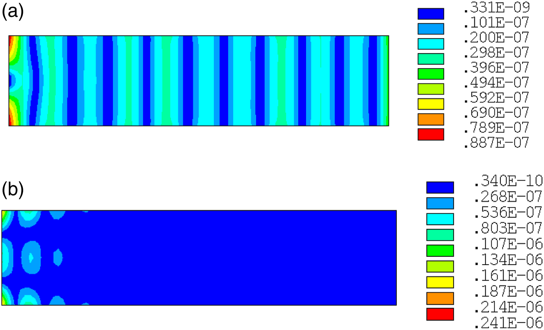
Experimental measurements
Experimental implementation
To demonstrate the existence of FWBGs in the PUSP further, the flexural vibration transmission experiments were performed on a 1:4 scaled PUSP, as shown in Figure 7. A flexible rope was used to hang the specimen, and the four sides of the specimen were unconstrained. The experimental sample used the materials discussed in the theoretical analysis in Section Model and calculation method. A force hammer was used at one end of the specimen to excite the system, and acceleration sensors were installed separately at the excitation point and the other end of the plate surface to monitor vibration acceleration. Experimental setup (unit: mm).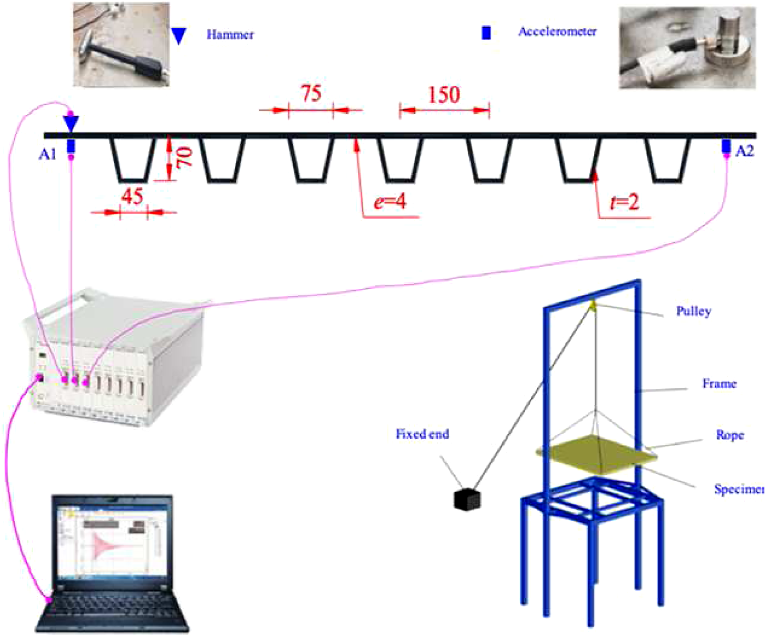
Comparison of measured and calculated results
The specimen band structure is obtained as shown in Figure 8(a) and contains three types of band gaps (266–609 Hz, 1205–1981 Hz, and 3307–3380 Hz) below 3500 Hz. The transmission spectra produced via the hammering test and using FEM are shown in Figure 8(b). In simulation, the boundary condition of the model is free on its four sides. The FE model was calibrated to achieve adequate correlation with experimental measurements. (a) Calculated band structure and (b) comparison of numerical and experimental flexural wave transmission spectra.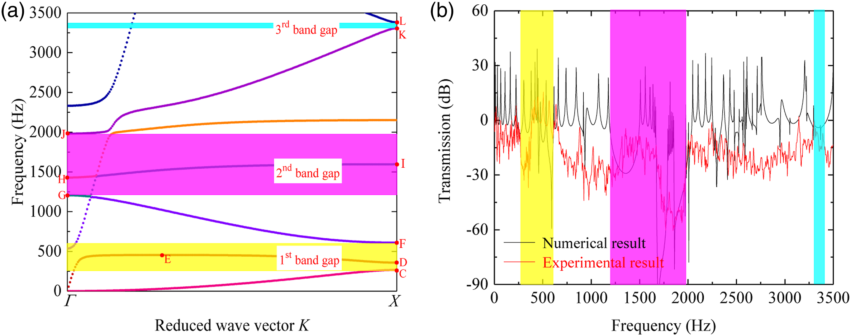
Two attenuation frequency ranges that correspond to the vibration attenuation region in the transmission spectrum are identified during the experiment. The experimentally measured third band gap is not as obvious as the numerical band gap given in Figure 8(a). Although some discrepancies between the numerical analysis and experimental results can be found in Figure 8(b), the frequency ranges of band gaps are similar between them, especially for the second band gap which is the dominant one. The possible reasons for the deviations between the simulated and measured results can be summarized as follows:
First, the experiment specimen includes a limited number of unit cells, unlike the simulated infinite periodic structure. Second, structural boundary conditions usually play non-negligible effect on the flexural wave propagation and vibration characteristics. Specifically, in the experiment, the specimen has a deflection caused by gravity that strengthens the plate stiffness. The actual stiffness distribution of the specimen is different from the FE model. Last, defects in the welds that connect the U-rib to the baseplate and the material damping effect are not considered in the calculation. Since the frequency range assessed in this paper is wide, it is not possible to attain a perfect coincide in every frequency between numerical and experimental results. This deviation phenomenon can also be found in other related references.18,25 Overall, the computational and experimental errors are acceptable.
The eigenmode displacement fields of the lower and upper edges of the three FWBGs in Figure 8(a) are presented in Figure 9. They are in line with the analysis results in Section The band gap mechanism. Therefore, it can be concluded that the numerical model and experiments used in this study are reliable and parametric analysis may be applied to them. Eigenmode displacement fields of modes C–L identified in Figure 8(a).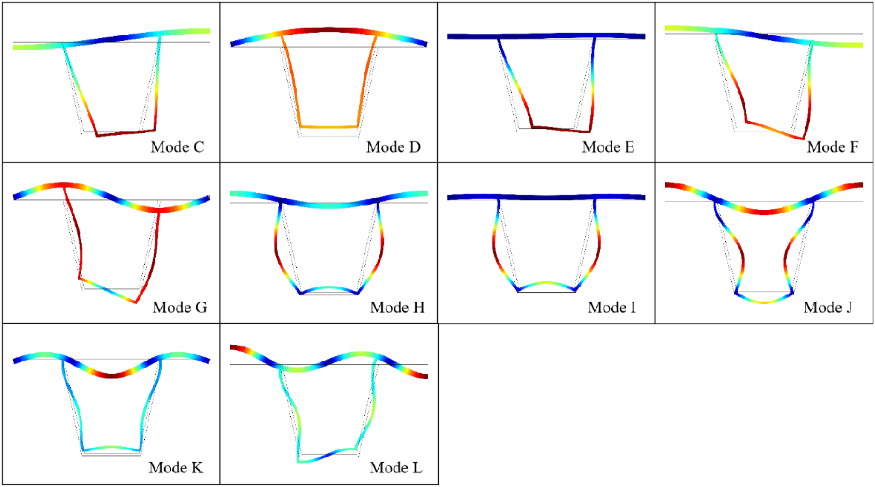
Parametric analysis and application
Band gap comparisons of different U-rib stiffened plates
To understand the influences of various geometric parameters on the FWBGs, the starting frequency, ending frequency, and frequency width were calculated.
First, the effect of the top plate thickness on the FWBG was studied. Four different top plate thicknesses ranging from 12 mm to 18 mm were considered because they are commonly used in real bridges. The other parameters remained unchanged. One can observe from Figure 10(a) that the top plate thickness has different effects on different band gaps. Because the stiffness of the top plate along the x-direction increases with the top plate thickness, the FWBGs move together to the high-frequency range and the third band gap moves to the high-frequency range in a more substantial manner. Note that both the stiffness and mass of the top plate increase with its thickness. The fact that the FWBGs move together to the high-frequency range is that the increased stiffness effect is more dominant than the increased mass effect. At the same time, due to changes in the top plate stiffness, the starting and ending frequencies of the band gaps move to high frequencies differently. This leads to some narrowing of the band gap. As a result, the FWBGs move to a higher frequency region and become narrower. The band gap frequencies vary with the (a) top plate thickness e; (b) U-rib thickness t; (c) U-rib spacing a; and (d) upper U-rib width l.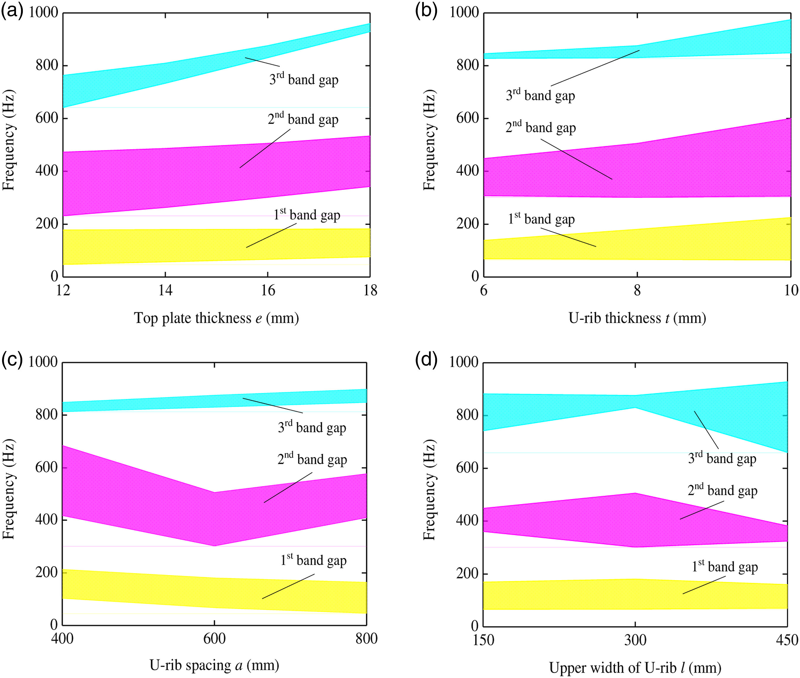
The dispersion relations of PUSPs with t = 6 mm to t = 10 mm are shown in Figure 10(b). The U-rib stiffness and mass increase with the U-rib thickness. The effect of the U-rib as a local resonator is amplified, and local resonance between the U-rib and the baseplate is enhanced. Changing the U-rib thickness causes the ending band gap frequencies to increase and the band gaps to widen.
Figure 10(c) and (d) show the effects of the U-rib spacing a and upper U-rib width l on the FWBGs. The influences of these parameters on the FWBGs are complex. Changing the U-rib spacing not only changes the stiffness of the structure but also changes the lattice constant. Therefore, varying the U-rib spacing changes the relationships that govern the band gap. When the upper U-rib width l changes, the position of the connection between the U-rib and baseplate and the degree of resonance coupling between the U-rib and baseplate both change. Since different band gaps correspond to different bending vibration modes, the influences on them from resonance coupling are not similar.
The change of U-rib spacing and upper U-rib width alters the intrinsic frequency of U-ribs, and it is found in this paper that the PUSP FWBG formation is closely related with the resonance coupling between the baseplate and U-ribs. The frequency position of the resonant band gap is determined by the natural frequency of the local resonance, which can be estimated according to the equivalent mass and equivalent stiffness of U-ribs. The width of the resonance band gap is mainly determined by the degree of localization of the local resonance mode and its coupling with the baseplate. From above analysis, changes in the U-rib spacing a and upper U-rib width l have substantial influences on the FWBGs. Thus, FWBG optimization can be performed using these two parameters.
Preliminary engineering application
The above parametric analysis shows that manual adjustment and active control of the band gap can be achieved by changing the geometric parameters of the PUSP. This method can be used to produce a band gap range that is in line with vibration and noise requirements.
For demonstration, Figure 11(a) and (b) show a new PUSP band structure and transmission spectrum obtained by changing the geometric parameters of the U-rib. For comparison, the transmission spectrum and band gap of the original PUSP are shown in Figure 11(a). After optimization, e = 12 mm, t = 6 mm, a = 600 mm, and l = 450 mm. The top plate and U-rib thicknesses decrease by 4 mm and 2 mm, respectively; and the upper U-rib width increases by 150 mm relative to the original PUSP. The optimized periodic U-rib stiffened plate (e = 12, t = 6, a = 600, l = 450; unit: mm): (a) flexural wave transmission spectrum and (b) band structure diagram.
It is clear that the band gaps of the new PUSP within the 1000 Hz frequency range are 53–80 Hz, 446–783 Hz, and 892–977 Hz. The second band gap changes significantly from 302–494 Hz to 446–783 Hz, that is, the band gap range becomes wider. In addition, vibration attenuation of the new PUSP in this band gap range is much more significant than that noted in the original system.
Conclusions
The major conclusions of this study are as follows: 1. The primary reason for band gap formation in the PUSPs is that flexural vibrations along the x-direction in the baseplate are absent due to the introduction of the U-rib (i.e., resonant element). There are three band gaps within 1000 Hz, that is, 69’158 Hz, 302–494 Hz, and 800–884 Hz. The second band gap plays a critical role in controlling vibration and noise because of its broad bandwidth and proximity to the dominant frequency band of steel bridge noise. 2. The flexural wave band gaps can be controlled artificially by adjusting various geometric parameters. Specifically, the second band gap varies substantially when the baseplate thickness is increased. Upon increasing the U-rib thickness, the second band gap ending frequency increases and the bandwidth becomes wider. Changing the U-rib spacing and upper U-rib width influences the FWBGs substantially, but no clear band gap change rule is identified since the PUSP FWBG formation is closely related with the resonance coupling between the baseplate and U-ribs. 3. Based on a preliminary numerical analysis, an optimized PUSP with parameters e = 12 mm, t = 6 mm, a = 600 mm, and l = 450 mm exhibits a wider band gap (446–783 Hz) and higher vibration attenuation than the original PUSP. Therefore, the PUSP FWBGs have high practical application value.
Footnotes
Declaration of conflicting interests
The author(s) declared no potential conflicts of interest with respect to the research, authorship, and/or publication of this article.
Funding
The author(s) disclosed receipt of the following financial support for the research, authorship, and/or publication of this article: The authors gratefully acknowledge financial support from the National Natural Science Foundation of China (Grant Nos. 51778534 and 51978580).