
Abstract
Mechanical vibration is mostly harmful, and it may not only generate noise but also affect the working life of the equipment. Lever, inerter, and grounded stiffness have good performance in the field of vibration control, but the dynamic vibration absorber simultaneously containing lever, inerter, and grounded stiffness is rarely studied. Based on the grounded dampertype dynamic vibration absorber, a dynamic vibration absorber with lever, inerter, and grounded stiffness is presented. And the optimal system parameters are analytically researched in detail. Firstly, the differential equation of motion is established according to Newton’s second law, and the analytical solution of the system is obtained. According to the amplitudefrequency curve of the system, it is obvious that there are two fixed points unrelated to the damping ratio. Meanwhile, the optimal frequency ratio of the dynamic vibration absorber is obtained based on the fixed-point theory. Under the premise of ensuring the system stability, the optimal grounded stiffness ratio is screened out, and the working range of inerter is further calculated. It is found that the inerter ratio has two working ranges when the coupling term values of magnification ratio and mass ratio are different. Furthermore, the approximate optimal damping ratio is derived by minimizing the maximum value of the amplitudefrequency curve. Using MATLAB, the numerical result is analyzed, and the correctness of analytical results is verified. Compared with other dynamic vibration absorbers under harmonic and random excitations, it is known that the model in this paper can evidently reduce the resonance amplitude and broaden the vibration band of the primary system. These results may provide a theoretical basis for the optimal design of similar dynamic vibration absorbers.
Keywords
Introduction
The dynamic vibration absorber (DVA) is one of the common devices in vibration control, which relies on attaching a free-to-vibration mass to the primary structure to suppress the system motion. It is widely used in engineering fields such as transportation, civil structures, and industrial machinery. The first DVA without damping was invented by Frahm. 1 However, this DVA only worked in a narrow applicable frequency range. Den Hartog and Ormondroyd 2 firstly used damping in the designing of a DVA to overcome the above defect. They found this type of DVA can effectively suppress the amplitude of the primary system and broaden the vibration frequency, which was widely known as Voigt type DVA. In addition, they also found that there were two fixed points on the amplitudefrequency response curve of the primary system which were independent of the damping ratio, so the fixed-point theory was proposed. Based on the fixed-point theory, the optimal frequency ratio and optimal damping ratio of Voigt type DVA were calculated by Hahnkamm 3 and Brock. 4 When damping existed in the primary system, a design method of the DVA was studied and proposed by Nishihara and Asami,5-7 and the accurate and optimal solution of the Voigt type DVA was also deduced. The application value of the results in practical engineering was verified by the fixed-point theory. The grounded damping dynamic vibration absorber was studied by Ren 8 and Liu 9 to improve the vibration control effect by optimizing the grounded damping. Viscoelastic materials were widely used in vibration control engineering and had damping properties and stiffness properties concurrently. Therefore, a three-element type DVA with better control performance was presented by Asami,10-11 and the designing parameters were optimized. Shen et al.12-14 studied the approximate analytical solutions and the parameters optimization of four kinds of semi-active onoff control DVAs. And they proposed a single-degree-of-freedom passive vibration isolation system with the same performance as the active vibration isolation system. A new quasi-zero-stiffness vibration isolation device was proposed by Li et al., 15 and the vibration isolation effect was studied. Yuan et al. 16 studied the influence of different controllers on the performance of a quasi-zero-stiffness hydraulic dynamic vibration absorber. Another quasi-zero-stiffness DVA was proposed by Chang et al., 17 which could effectively suppress the ultra-low frequency vibration of the primary system.
With the increasing requirements for vibration control in the field of high precision, many researchers tried to apply negative stiffness devices to the field of vibration isolation and achieved some remarkable results. Alabuzhev et al. 18 introduced the theory and application of vibration isolation with negative stiffness in their monograph. An undamped DVA with negative stiffness was proposed by Acar et al., 19 which could effectively reduce the amplitude of the primary system. Shen et al.20-22 applied negative stiffness elements to a variety of DVAs, and proved that reasonable negative stiffness would improve vibration damping performance. Particularly, it is found in the literature 22 that the DVA with positive grounded stiffness had the best control effect, when the coupling terms of magnification ratio and mass ratio reached a certain value.
The concept of inerter was introduced by Smith, 23 which was a two-terminal mechanical element that the force applied on the terminals was proportional to the relative acceleration between the two terminals. Lazar et al. 24 introduced an inerter into a multi-storey building and found that it could achieve an excellent level of vibration reduction. Chen et al. 25 studied the influence of an inerter on the frequency of a vibration isolation system. Hu et al.26,27 and Wang et al. 28 studied DVAs with inerters, which were optimized by using fixed-point theory and numerical algorithm. It was found that installing an inerter could improve the performance of DVA, but the inerter should be placed in a suitable position. Two types of DVA models with inerter and negative stiffness to restrain the transverse vibration of beams were proposed by Chen et al. 29 Marian et al. 30 studied the tuned mass damper-inerter (TMDI) and found that the TMDI is more effective to suppress vibrations close to the natural frequency, while it was more robust to detuning effects. Jangid 31 investigated the optimum parameters and performance of the tuned inerter damper (TID) for the base-isolated structure and evaluated the stochastic response under white-noise excitation. Djerouni et al. 32 proposed a double-mass tuned damper-inerter (DTMDI) and optimized the parameters of TMDI and DTMDI using a genetic algorithm. John et al. 33 presented a novel type of frictionless mechanical inerter device which used living-hinges to achieve the motion of the flywheel. Wang et al. 34 presented a semi-active inerter which was used for the vibration isolator. Tang et al. 35 studied the dynamic characteristics of skyhook semi-active inerter-based vibration isolator, which had lower absolute displacement peak and wider vibration isolation frequency band.
As a simple mechanical element with the function of amplifying force, a lever could be used to suppress vibration in systems. The lever was introduced into the vibration isolation system by Flannelly. 36 And a dynamic anti-resonance vibration isolator was designed, which amplified the inertial force generated by the mass to offset the spring force to achieve anti-resonance. It was found that when the same vibration isolation effect was obtained, the mass with an amplifying mechanism would be smallest. Xing et al. 37 applied the lever to the DVA with negative stiffness, and studied the optimal parameters. Sui et al. 38 introduced the amplifying mechanism, inerter, and grounded stiffness into Voigt type DVA, and it was found that the system would be unstable if the inerter was inappropriate. Yang et al. 39 optimized the design of lever-type tuned mass dampers, which were used to control the wake-induced vibrations of coupled twin-cable hangers.
According to the above-mentioned explanation, it is obvious that the lever, inerter, and grounded stiffness all have wide applications in vibration control engineering. This paper presents a DVA model simultaneously containing the above three components. The proposed model parameters are optimized by using the fixed-point theory. The numerical result shows that the calculation process of analytical solution is accurate. The obtained results are compared with other DVAs, and it is proved that the presented model in this paper shows better control performance, which provides a choice for the design of a new DVA.
The rest of this paper is organized by the following sections. The Model of DVA and Parameters Optimization section shows the optimal parameters of the primary system based on the fixed-point theory, and discusses the working range of inerter. In Section 3, the correctness of the analytical solution is verified by numerical simulation, and the presented model is compared with other DVAs under harmonic and random excitations. Finally, the conclusion is presented in Section 4.
The model of DVA and parameters optimization
The model presented in this paper is shown in Figure 1. It is a grounded dynamic vibration absorber containing an amplifying mechanism (a lever is taken as an example) and inerter. The primary system and subsystem are connected by a lever to form a complete system. m1 and m2 present the masses of the primary system and subsystem, respectively. k1 and k2 denote the stiffnesses of the primary system and subsystem, respectively. The grounded spring stiffness is k3, the subsystem damping coefficient is c, and the inerter coefficient is b. r1 and r2 denote the distances from the lever support point O to the hinge points M and N of the two sliding blocks, respectively. The amplitude and frequency of the exciting force are F0 and Mechanical model of dynamic vibration absorber.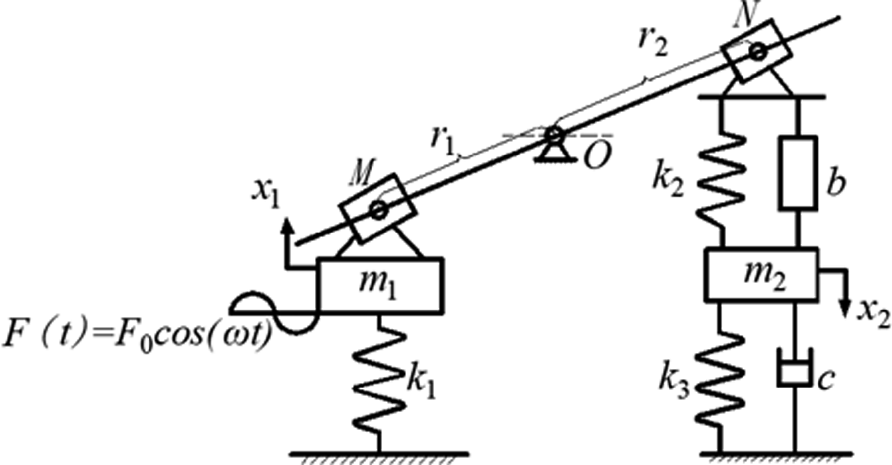
By ignoring the mass of the amplifying mechanism and the friction in the motion procedure, the dynamic equation of the system can be established by Newton’s second law as
Using the following parametric transformation

Equation (1) can be simplified to
The analytical solution
The steady-state solution of equation (2) has the following form


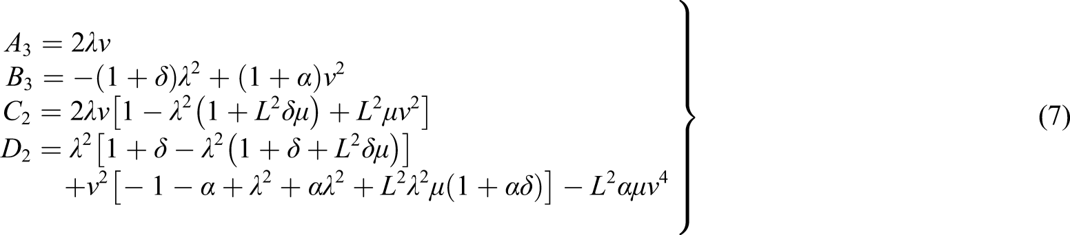
Introducing the parameters

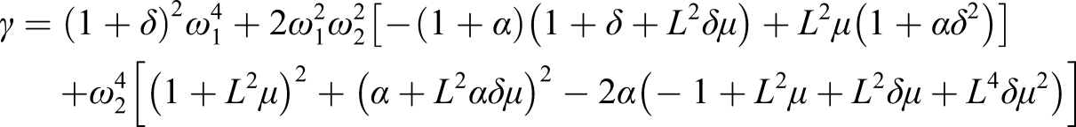
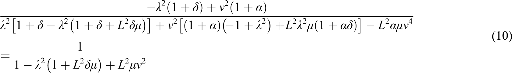
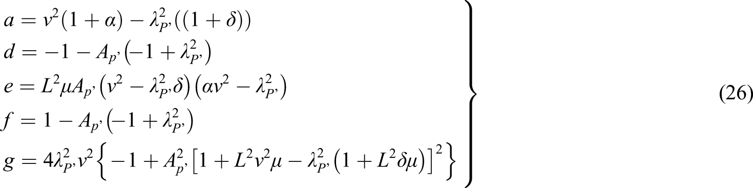
The natural frequency of the system can be obtained by setting the denominator of equation (6) equal to zero, so that one can get

Parameters’ optimization
According to the fixed-point theory, it is easily found that there are two fixed points on the normalized amplitudefrequency curve that have nothing to do with the damping ratio when considering equation (6). Some typical normalized amplitudefrequency curves for different damping ratios such as 0.2, 0.3, and 0.6 are given in Figure 2. It can be clearly seen that all the curves pass through two fixed points P and Q for different damping ratios. And the point Z is a stationary point that corresponds to zero frequency and is also independent of damping ratios. The normalized amplitude-frequency curves for different damping ratios.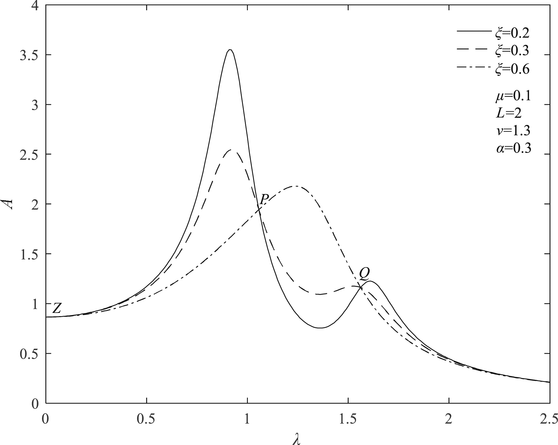
Since the two fixed points P and Q are unrelated to the damping ratio, the response values of the primary system are equal when the damping ratio approaches zero and infinity in equation (6). That is

Substituting equation (7) into equation (9), one can obtain
Considering meaningful situations and simplifying equation (9), one can get

Assuming that equation (11) has two real roots, that is,

The purpose of optimization is to minimize the maximum value of the amplitudefrequency curve, that is, the two fixed points should be adjusted to the same height, and the highest point of the amplitudefrequency curve exactly fall on the two fixed points.
Because the response values at

Then, equation (13) can be reorganized as

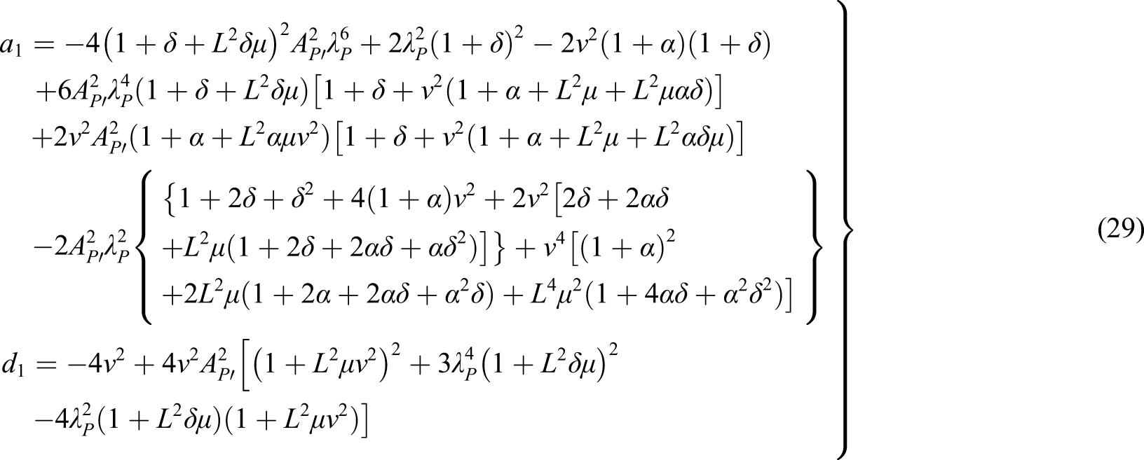
Combining equations (12) with (14), one can find

Solving equation (15), the optimal natural frequency ratio can be obtained as

The abscissas at the two fixed points can be obtained by substituting equation (16) into (10)


When the frequency ratio achieves the optimal value, the response at the two fixed points P and Q can be found
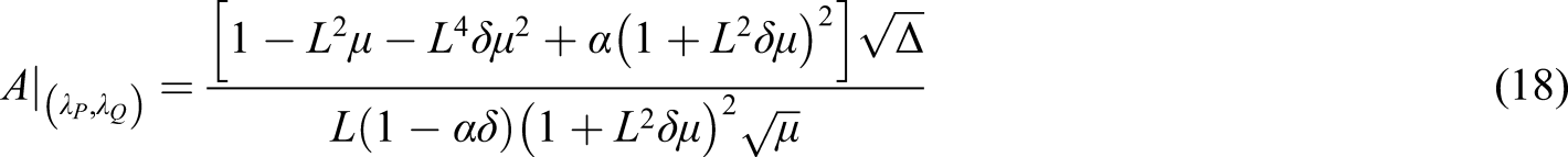
It can be known from equation (18) that the control performance of the system is only determined by the grounded stiffness ratio, when mass ratio μ, magnification ratio L, and inerter ratio

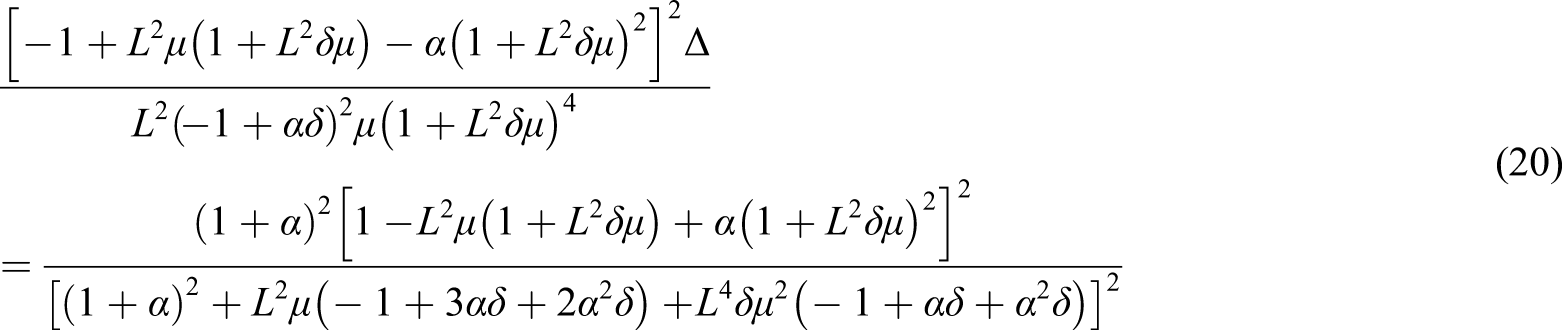
Solving equation (20), one can get all possible optimal grounded stiffness ratios


It has been pointed out that the above six alternative optimal solutions will make the system unstable when the inerter ratio is inappropriate.
38
Therefore, when selecting the appropriate stiffness ratio, it should be carried out under the premise of ensuring system stability. The above grounded stiffness ratios are substituted into equation (16), respectively. Then, setting it to be greater than zero to solve the inerter ratio

So far, the optimal frequency ratio and optimal grounded stiffness ratio are obtained. Simultaneously, the two fixed points P and Q have been adjusted to the same height. As the coordinates of the two fixed points P and Q are independent of the damping ratio, the two fixed points should become the highest point of the amplitudefrequency curve so as to achieve the optimal control performance. According to the extreme value condition, it could be achieved if the derivatives of the amplitudefrequency curve at the two fixed points are zero, that is

By solving equation (23), one can get the damping ratio when the two fixed points P and Q become the highest points of the amplitudefrequency curve. Then, the optimal damping ratio
In order to make the amplitudefrequency curve pass through point P levelly, we can assume that it passes through the adjacent point
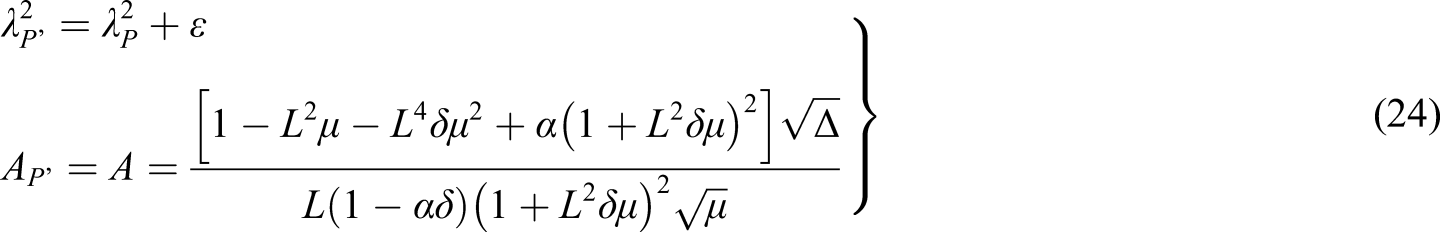
By substituting equations (24) into (6), one can get

After expanding equation (25), it can be written as

Equation (25) will assume the indeterminate with the form

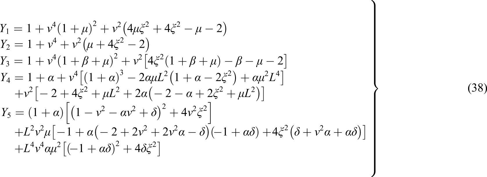
Therefore, we only need to find all the coefficients of the first-order term in the numerator and denominator of equation (27)
Substituting equations (16), (17a), (18), and (22) into equation (28) yields

Similarly, the damping ratio when the highest point of the amplitudefrequency curve is located at the point Q can also be obtained as

According to the above calculation, the approximate optimal damping ratio of the model is finally obtained as

So far, all the parameters of this model have been optimized.
The working range of inerter
Observing the optimization parameters and calculation process, the working range of the inerter should satisfy the following conditions at the same time: the natural frequencies of the system are positive, the lower part of the radical is positive, the denominator of each expression is not equal to zero, and the optimal frequency ratio

Therefore, inerter ratio
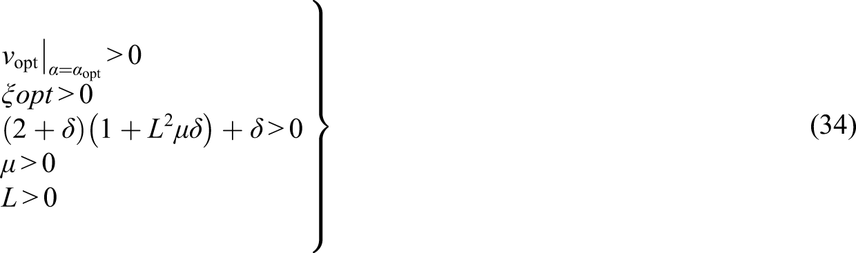
Solving equation (34), one can get the working ranges of the inerter as


The results show that the working range of the inerter is different when the coupling term of the magnification ratio and mass ratio are different values.
Analysis of results
Numerical simulation
The parameters of the system for two cases.
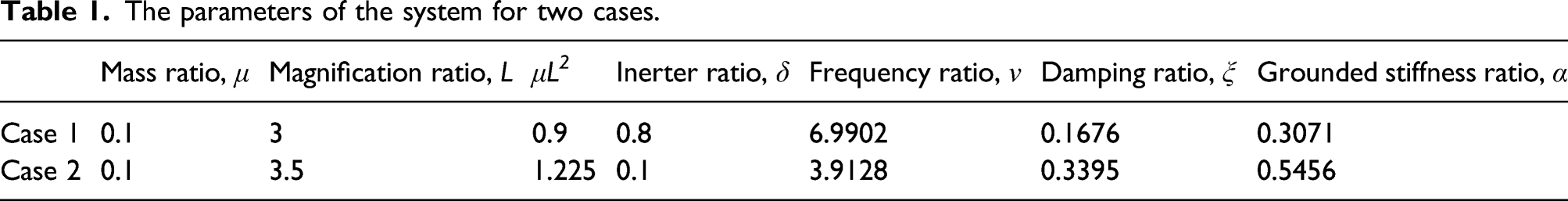
The numerical solution is presented by the fourth-order RungeKutta method. The analytical and numerical solution curves of the primary system for two cases are shown in Figure 3, where (a) denotes the analytical solution and (b) represents the numerical solution. The numerical and analytical solutions for two cases are completely consistent, which verifies the correctness and higher precision of the above solution process. Comparison between numerical simulation and analytical solution for two cases.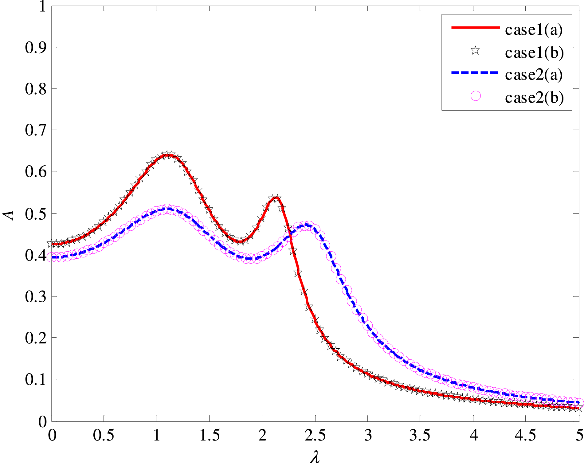
Analysis of the influence of system parameters on response characteristics
The influence of system parameters on optimal parameters
Taking the coupling term of the mass ratio and magnification ratio as the abscissa and the inerter ratio as the ordinate, the relationship between optimal parameters and system parameters μ, L, and δ are shown in Figure 4. Based on the figure, the system remains stable within the selected parameter range. The relationship between optimal parameters and system parameters.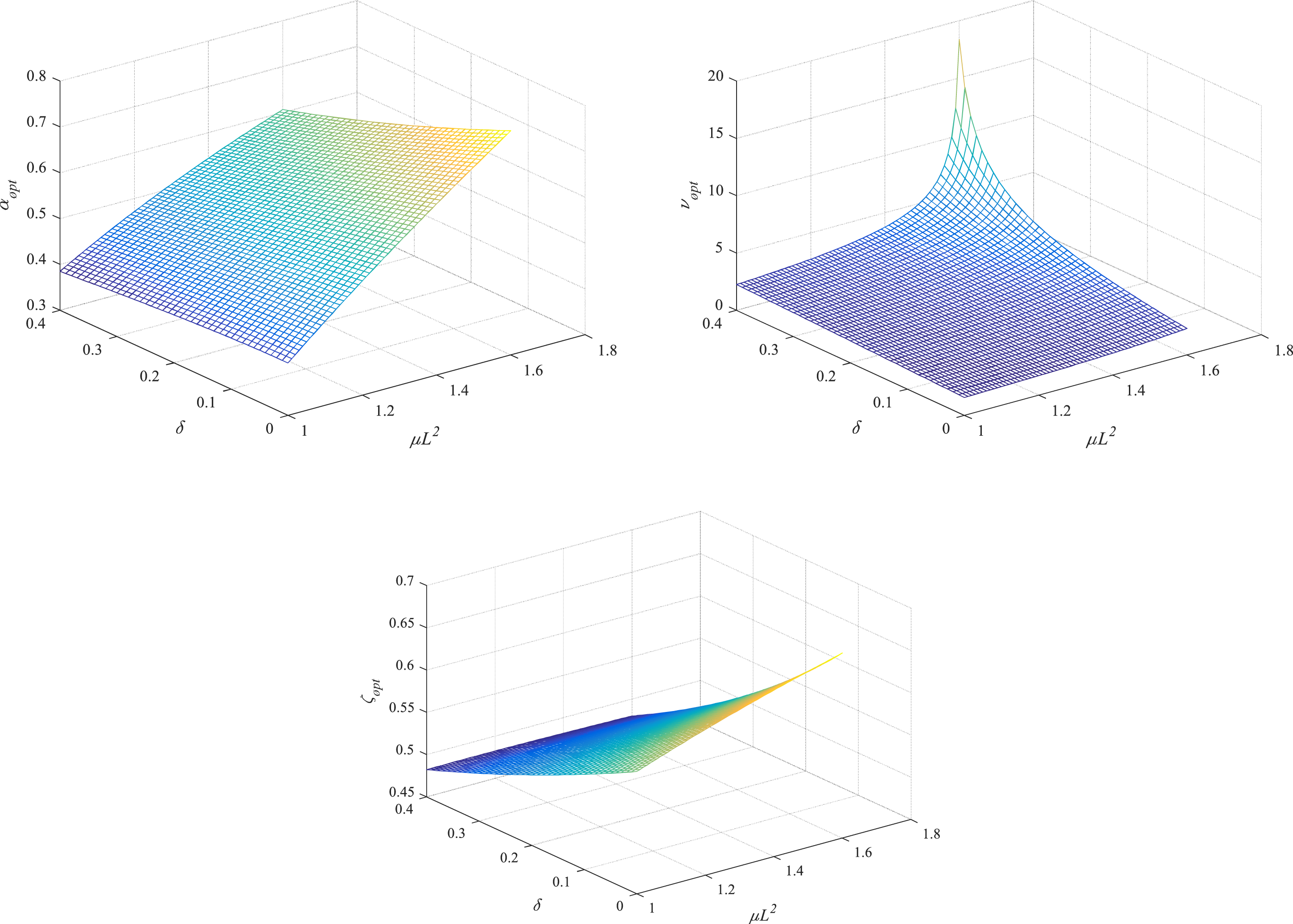
The influence of magnification ratio on the response of the primary system
The mass ratio The effect of the magnification ratio on the response of the primary system.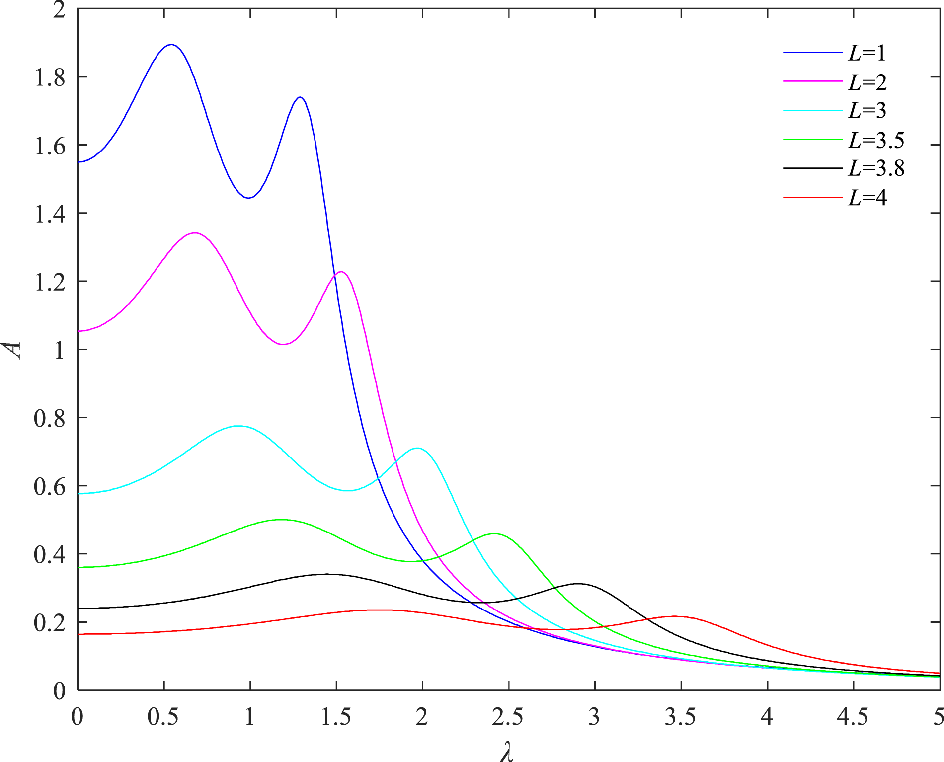
The influence of inerter ratio on the response of the primary system
The mass ratio The effect of the inerter ratio on the response of the primary system.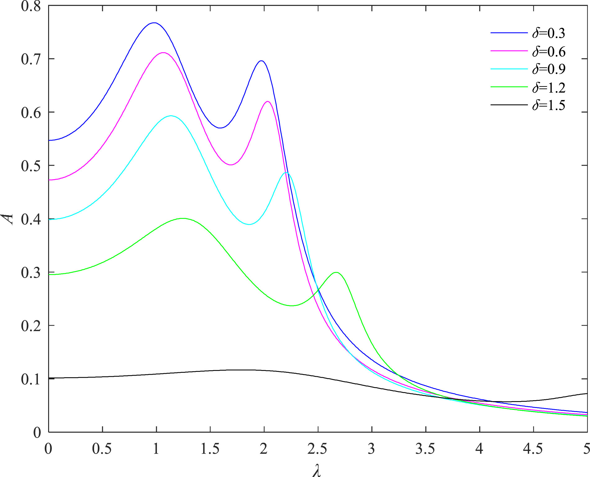
Comparison with other DVAs
In order to verify the control performance of the presented DVA for two cases in this paper (called as LB type DVA), this model is compared with the typical Voigt type DVA, the grounded damping type DVA,8-9 the grounded inerter type DVA,
30
and the grounded damping type DVA with lever and negative stiffness element in the literature
22
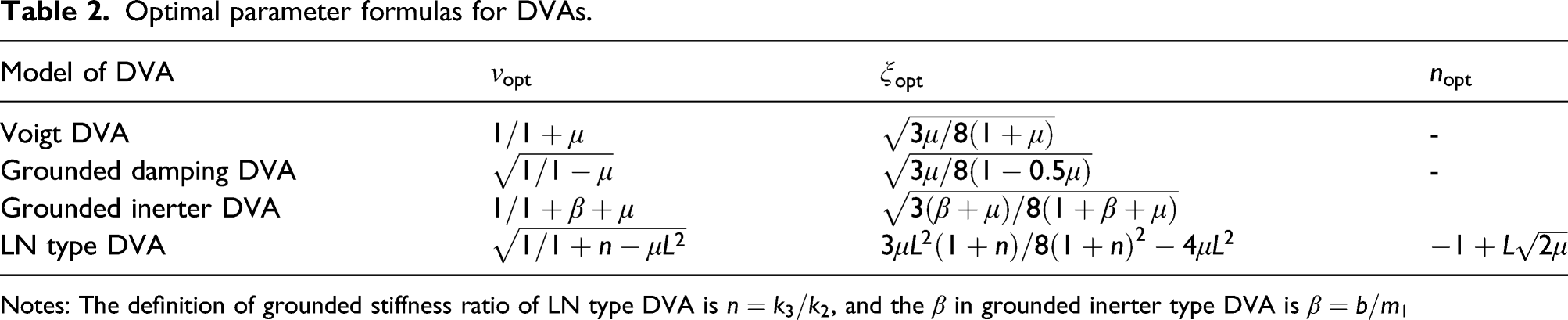
(called as LN type DVA). Four comparative vibration absorber models are shown in Figure 7. The optimal parameters formula for each model is given in Table 2. The models of three types of dynamic vibration absorbers: (a) Voigt type DVA, (b) grounded damping type DVA, (c) grounded inerter type DVA, and (d) LN type DVA. Optimal parameter formulas for DVAs. Notes: The definition of grounded stiffness ratio of LN type DVA is 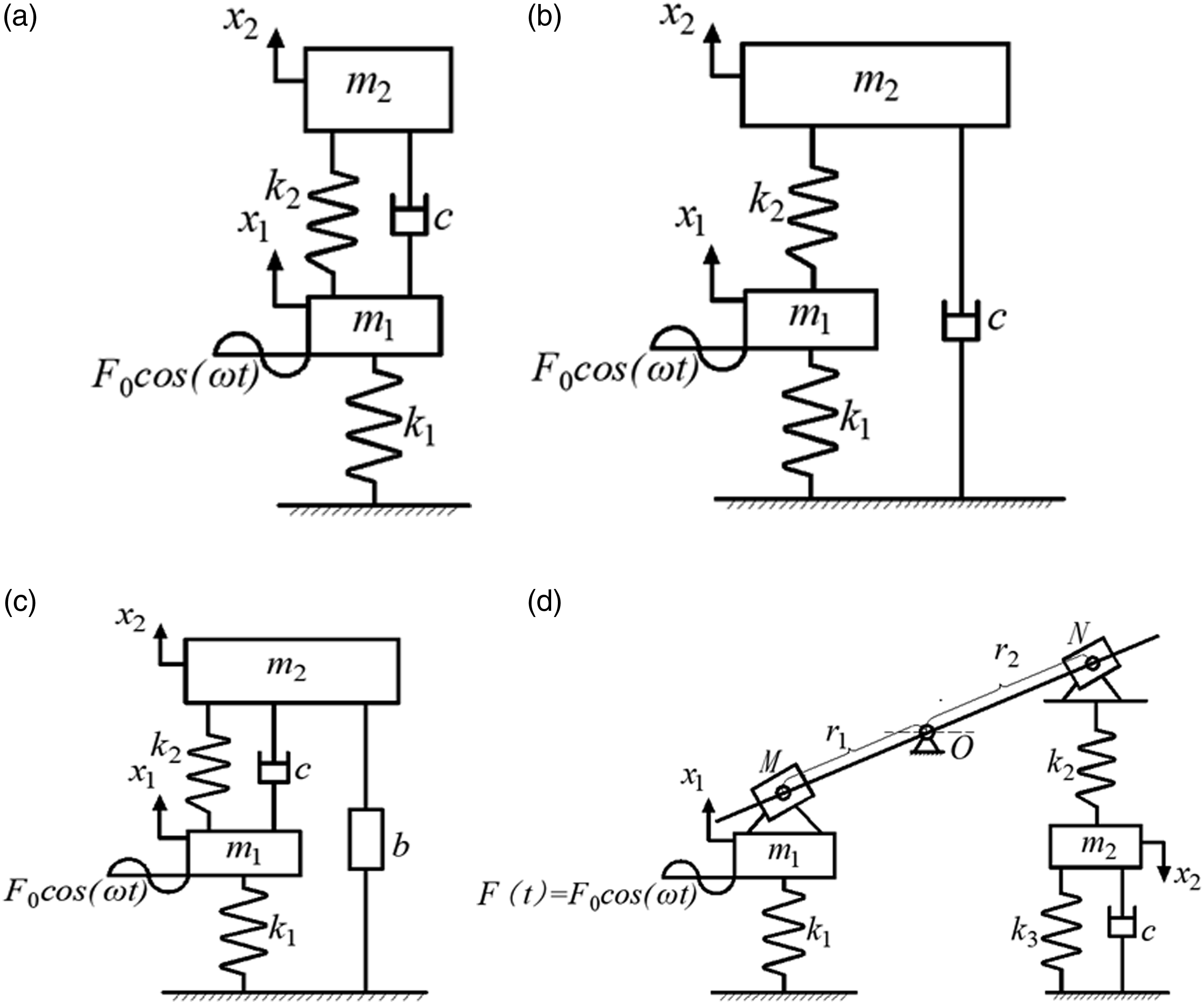
The response of the primary system to harmonic excitation
The mass ratio is selected as Comparison with other DVAs.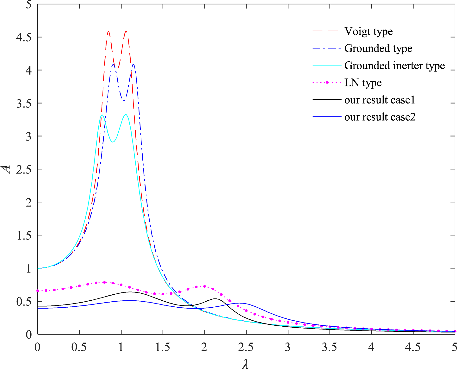
There is a conclusion from Figure 8 that the DVA for two cases in this paper and the LN type DVA can greatly reduce the resonance amplitude and broaden the vibration band of the primary system compared with the classic DVAs, that is, the Voigt type DVA, grounded damping type DVA, and grounded inerter type DVA. Compared with the LN type DVA, the resonance amplitude of the model in this paper is much lower after adding the inerter when the same mass ratio and amplification ratio are selected.
The response of the primary system under random excitation
In actual engineering, the source of external excitation is mostly random or with strong randomness. Therefore, it is important to study the response of the primary system under random excitation. Assuming the primary system is subjected to random excitation with zero mean and the power spectral as 
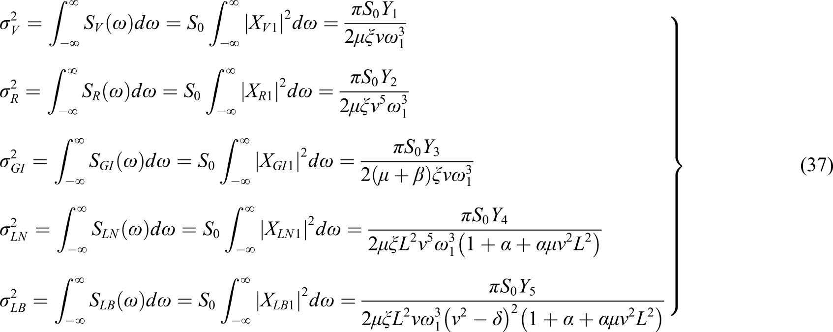
The parameters of the primary system are the same as in Section 3.3.1, and the mean squares of the primary systems of all the DVAs could be calculated as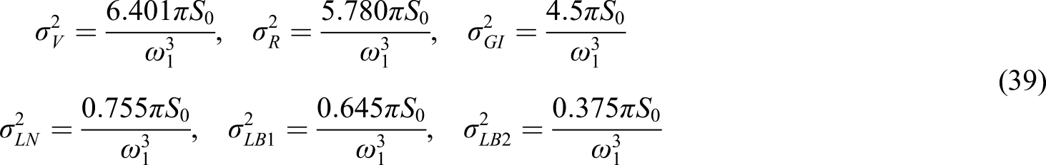
The variances and reduction ratios of the primary system.
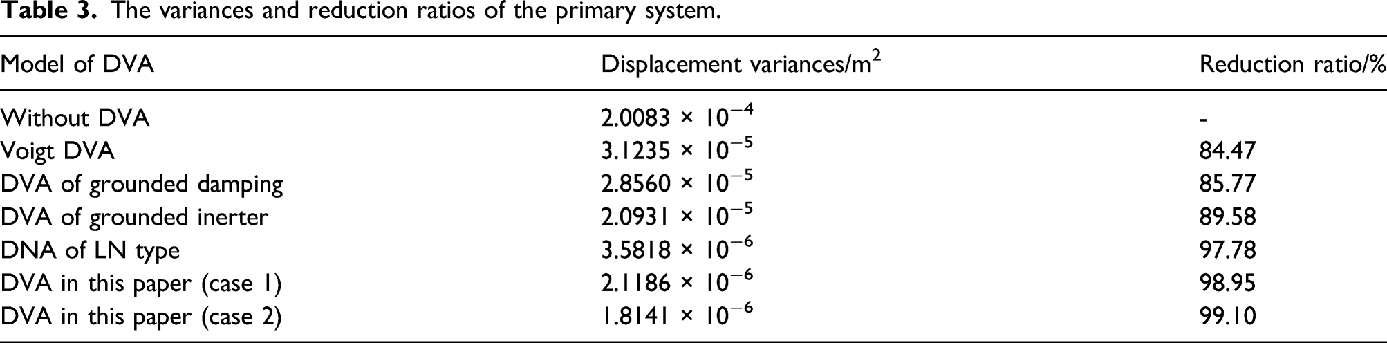
It can be seen from Table 3 that although the presented model was designed according to the H∞ optimization criterion, it still can greatly reduce the vibration energy of the primary system in the entire frequency range under random excitation. That means the presented model has better vibration damping performance than others. The primary system will have better vibration damping performance when the coupling terms μL 2 is in the range of 1 to 2.
Conclusions
A novel type of DVA with lever, inerter, and grounded stiffness is investigated. The parameters of this model are optimized based on fixed-point theory. And the optimal frequency ratio, optimal grounded stiffness ratio, approximate optimal damping ratio, and working range of inerter are obtained. The results show that the working range of the inerter is determined by the coupling term of magnification ratio and mass ratio. The vibration reduction effect is better when the coupling term is in the second range. Compared with other DVAs under harmonic and random excitations, the introduction of a reasonable grounded stiffness, inerter, and lever can greatly reduce the response amplitude and effectively broaden the vibration damping frequency of the primary system.
Footnotes
Declaration of conflicting interests
The author(s) declared no potential conflicts of interest with respect to the research, authorship, and/or publication of this article.
Funding
The author(s) disclosed receipt of the following financial support for the research, authorship, and/or publication of this article: This work was supported by the National Natural Science Foundation of China (Grant No. U1934201 and 11772206).