
Abstract
With the rapid development of aero-engine manufacturing technology, the dual-rotor system has been employed in part of turbofan engine in order to improve the working performance of aircraft more efficiently. In this study, taking the counter-rotation dual-rotor as the research object, the dynamic model of dual rotor-casing coupling system is established by the aid of MATLAB. The dynamic frequency curves are in good agreement with the results in references and calculated by FEM method, that shows the validity and feasibility of the model. The local rub-impact dynamic model of dual rotor-casing coupling system is established, and rubbing analysis is carried out using Newmark-β method. The effects of rotating speed and speed ratio on local rub-impact response are deeply discussed. The results show that with the increase of rotating speed, combined frequencies and frequency multiplication components are more significant. In addition, speed ratio has a great influence on the periodic motion of the system. With the increase of the absolute value of the speed ratio, the whirl radius of the outer rotor and the normal rubbing force increase dramatically.
Introduction
The dual rotor system is widely used in aeroengine. In order to reduce vibration amplitudes and improve the performance of the whole machine, such as reliability, stability, and so on, the research of dual rotor structure is deeply studied. In the dual rotor system, a special intershaft-bearing structure connects the inner rotor and outer rotor, that causes the coupling of the vibration behavior of the inner and outer rotors. 1 The dynamic characteristics of the dual rotor system become more complex compared with single rotor system.
With less variables and equations, the transfer matrix method is more efficient to solve rotor dynamic problems. Considering the gyroscopic moment, shear deformation, and bearing characteristics, Bansal et al. 2 established the analytical structure matrix of the dual rotor system by the transfer matrix method. Using the Muller quadratic interpolation method, they obtained the complex eigenvalues and corresponding modes and analyzed the stability of the dual rotor bearing system. Adopting the transfer matrix method to establish the motion equation of the multiaxial rotating machinery, Hibner et al.3–5 calculated the critical speed and nonlinear damping response of the system and discussed the stability of the squeeze film damper bearing through theoretical and experimental analyses.
The modal synthesis method is widely used in calculating the eigenvalue of the system by computing the eigenvalues of multiple substructures. By the aid of the modal synthesis method, Glasgow et al. 6 established the motion differential equation of the dual rotor system and calculated the critical speed and mode shape of the system. They found that the modal truncation number had a great influence on the accuracy of the positive and negative precession frequency of the system. Without considering the damping of the system, Li and Gunter7,8 analyzed the application of the substructure mode synthesis method in the calculation of the natural characteristics of the dual rotor system. Through discussing the influence of the modal truncation error on the dynamic characteristics of the system, they depicted the reasonable range of the modal truncation number.
Considering the gyroscopic effect and bearing damping, Childs 9 established a typical dynamic model of the dual rotor system and analyzed the inherent characteristics on the basis of research of the traditional Jeffcott rotor. Considering the gyroscopic moment, bending, and shear deformation of rotating shafts, Chiang et al.10,11 adopted finite element method to study the dynamic characteristics of single axis- and dual axis-bearing turbomachinery systems. They analyzed the inherent characteristics of the system and discussed the influence of speed ratio of high- to low-pressure rotor on the critical speed.
Some scholars had carried out the experimental research on the dual rotor system. Gupta et al.12,13 calculated the critical speed, mode shape, and unbalanced response of the dual rotor system through the transfer matrix method. The accuracy of the results was validated through comparing with the test results obtained by a set of dual rotor test equipment. The influence of the coupling support between the inner and outer rotors was studied by the numerical simulation and the experimental method. In addition, Shafei, 14 Rajan, 15 Hu, 16 and Shiau 17 had also conducted relevant research on dual rotor systems.
In aeroengine field, rotor–stator rubbing is one of the most frequent faults. 18 Many scholars had studied the single rotor-casing rub-impact and achieved abundant results.19–26 Considering the influence of coating deposited on the outer surface of disc and the inner surface of casing on rub-impact, Yang et al.27,28 established a dynamic model of aeroengine in the case of the coupling fault of mass unbalance and local rub-impact. Based on Lankarani–Nikravesh model and Runge–Kutta numerical algorithm, they deduced a new rubbing force model and solved the dynamic rubbing response of system. Finally, the validity of the dynamic model was verified by comparing with the experimental results.
Considering the influence of gyroscopic effect, Sun et al.29,30 adopted multiharmonic balance combined with the alternating frequency/time-domain technique (MHB-AFT) to obtain the nonlinear dynamic equation of an 8-DOF dual rotor with rub-impact fault. The complex nonlinear phenomena caused by rub impact, such as combined harmonic vibration, hysteresis, and resonance peak shift, were solved by the aid of arc-length continuation method. The stability of numerical solution was discussed using Floquet theory. In order to further understand the steady-state response characteristics of the dual rotor system under blade-casing rubbing, they discussed the effects of different control parameters such as mass eccentricity, intershaft bearing stiffness, and rotating speed on the dynamic characteristics of the system.
Regarding the rub-impact plate as an elastic diaphragm, Xu et al. 31 proposed a new finite element rubbing model. Considering the elastic deformation, contact penetration, and nonlinear spring damping support, the transient response of the system under rubbing condition was solved based on the wheel rim-elastic diaphragm rubbing force model. The rub-impact experiments were carried out on the dual rotor test-bed, and the experimental results were very consistent with those of the theoretical simulation.
Considering the coupling effect of the high- and low-pressure rotor through the intershaft bearing and the disc deflection caused by gyroscopic effect, Jia et al. 32 established a new axial–radial coupling dynamic rubbing model for the counter-rotation dual rotor system. The detailed expressions of the bearing coupling forces were given according to the two different forms of intershaft bearing.
Based on the rigid-flexible coupling multibody model, Han et al. 33 established the local rub-impact model of the dual rotor system using MSC. By using ADAMS software, they analyzed the nonlinear dynamic characteristics of the system. Considering the flexibility of the casing, Wang et al. 34 established a collision force model between a disk and a fixed stopper using the Lankarani–Nikravesh model. Using numerical integration method, they discussed the influence of speed ratio, initial clearance, the mass eccentricity, and the bearing stiffness between the shafts on the nonlinear characteristics of the system under rubbing condition.
Lu et al. 35 presented a review of proper orthogonal decomposition (POD) techniques applied to order reduction in a variety of research areas. The applications of POD method in high-dimensional nonlinear dynamic systems were prospected in detail in order to provide direct guidance for researchers in various fields of engineering. Taking into account the nonlinearities of all of the supporting rolling element bearings, Jin et al. 36 established a dynamic model of a complex dual rotor-bearing system of an aero-engine based on the finite element method with rigid disc, cylindrical beam element, and conical beam elements. The nonlinear vibration responses of the dual rotor-bearing system were studied in the case of different clearances of the intershaft bearing. Lu et al. 37 applied the POD method to the dimension reduction of dual rotor-bearing experiment rig for the first time. The dynamical characteristics of the reduced-order model were compared with the full order system and experimental results, which verified that the POD method presented higher computational efficiency and accuracy.
On the basis of above research studies, this study establishes the coupling dynamic model of dual rotor-bearing-casing system, and the inherent characteristics of the system are analyzed, the accuracy of which is validated by comparing with the results in references. Using this model, the effect of rotating speed, speed ratio, and mass unbalance on the rubbing responses is studied. The evolution rules of the axis trajectory, the periodic motion, and bifurcation behavior of the system along with the variation of speed ratio are studied. The difference of dynamic responses between considering the rub impact or not is analyzed, and the influences of rub impact on axis trajectory, time-domain response, and amplitude spectrum are pointed out.
Dual rotor-casing system
Modeling
Figure 1 is a schematic diagram of the dual rotor-casing coupling system of the aeroengine, which consists of a high-pressure rotor (outer rotor), a low-pressure rotor (inner rotor), a casing coupled with the high- and low-pressure rotor, and some supports. Only the transverse and bending vibrations of the rotors are considered, while the translation along and torsional vibration around z-axis are ignored. Schematic of a dual rotor-casing coupling system.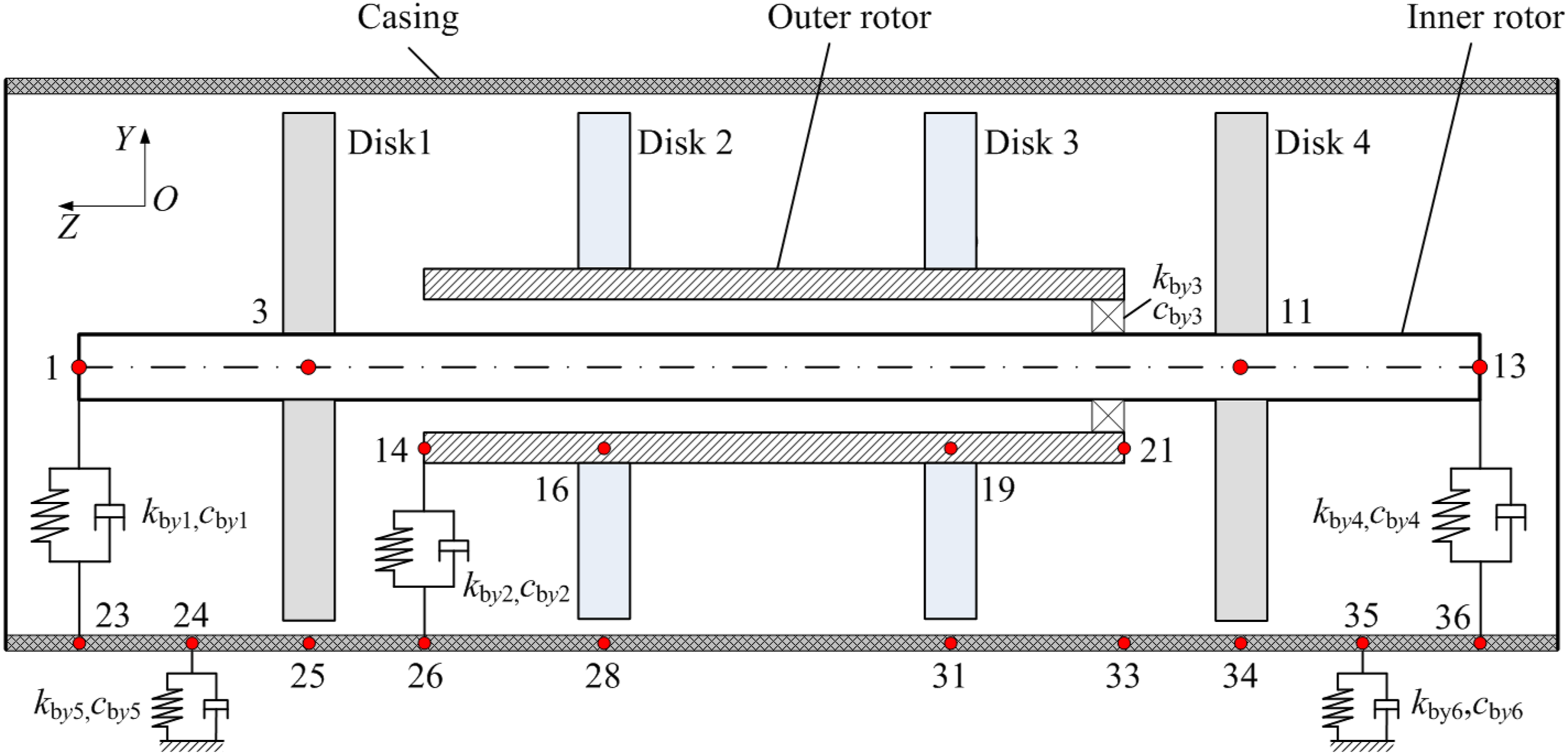
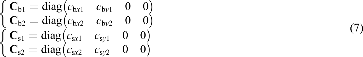
Timoshenko beams with constant cross-section are adopted to establish the model of the two rotors and the casing. The linear spring-damping model is used to simulate the casing-foundation, the inner rotor-casing, and outer rotor-casing supports. kbx1, kby1, kbx4, and kby4 are the support stiffness of the inner rotor-casing supports at the left and right ends in x- and y-directions, respectively. cbx1, cby1, cbx4, and cby4 are the damping of the inner rotor-casing supports at the left and right ends in x- and y-directions, respectively. kbx2, kby2, cbx2, and cby2 are the stiffness and damping of outer rotor-casing supports at the left end in x- and y-directions, respectively. kbx3, kby3, cbx3, and cby3 are the stiffness and damping of inner–outer rotor intershaft bearing in x- and y-directions. kbx5, kby5, kbx6, kby6, cbx5, cby5, cbx6, and cby6 are the stiffness and damping of casing-foundation supports at the left and right ends in x- and y-directions, respectively.
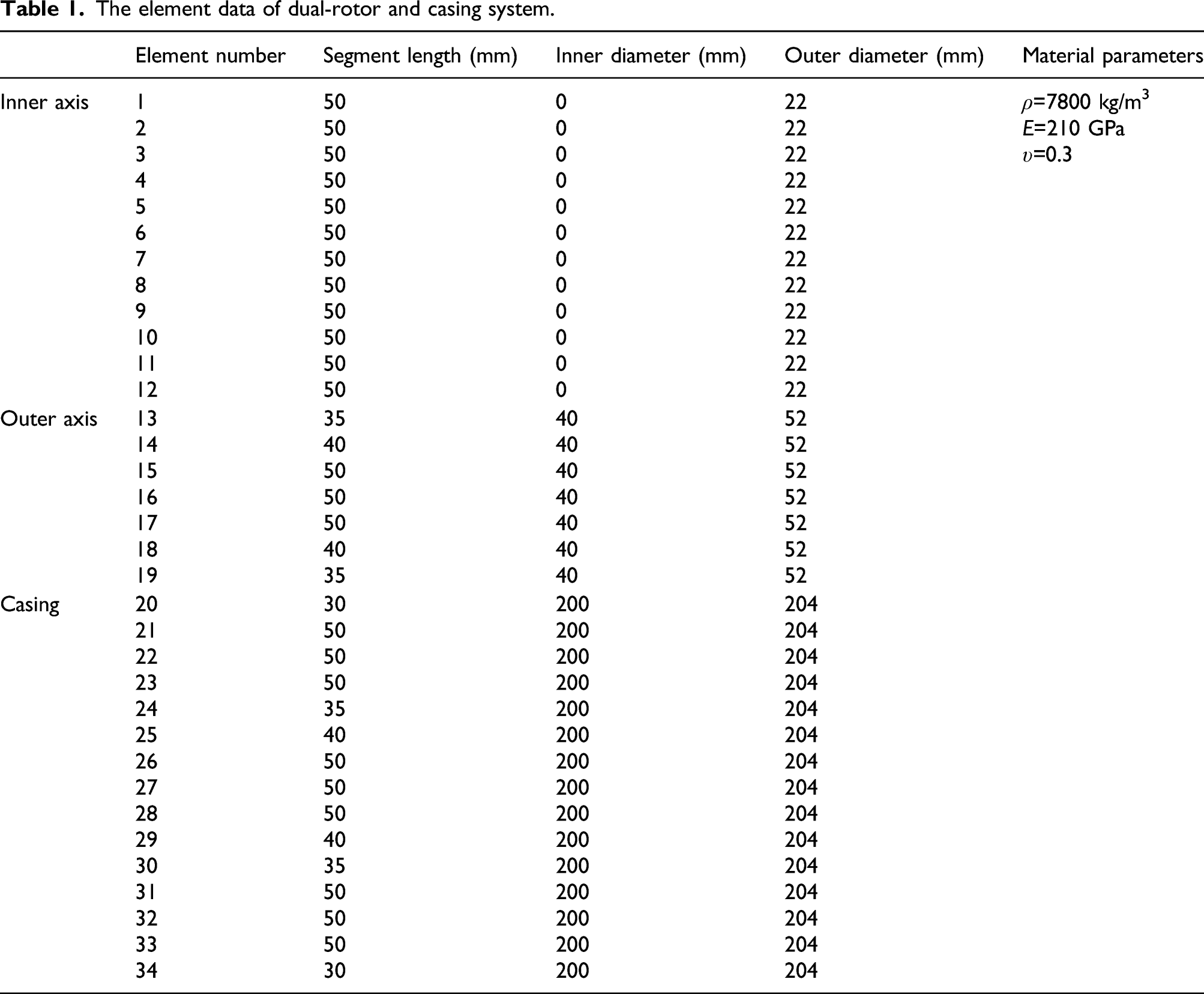
The element data of dual-rotor and casing system.
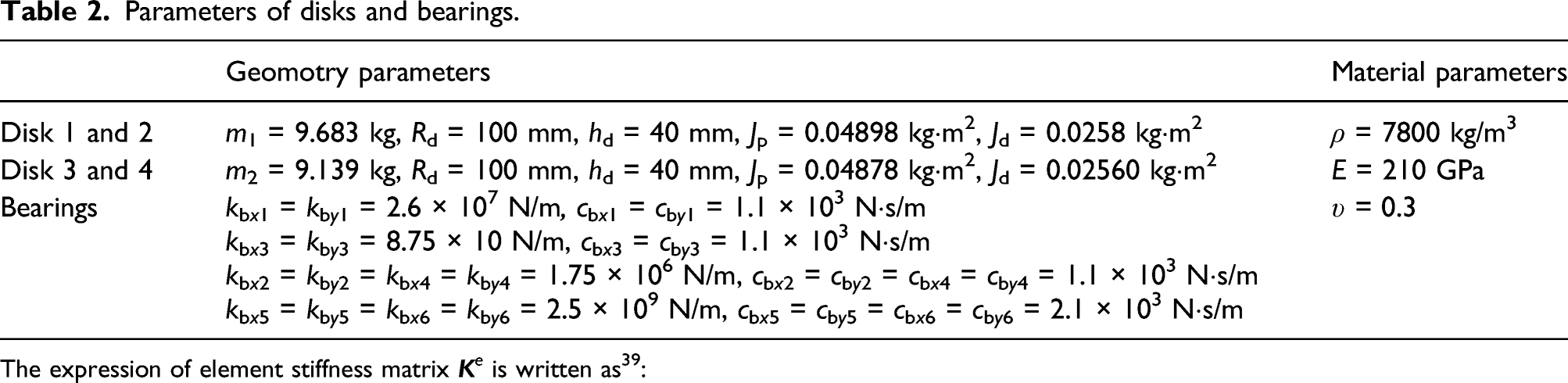
Parameters of disks and bearings.
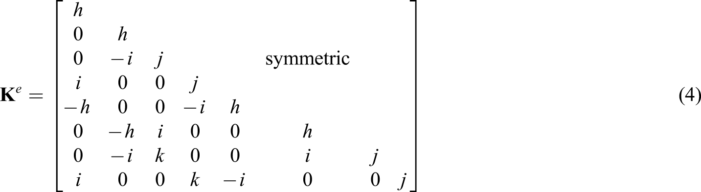
The expression of element stiffness matrix
The equations of motions
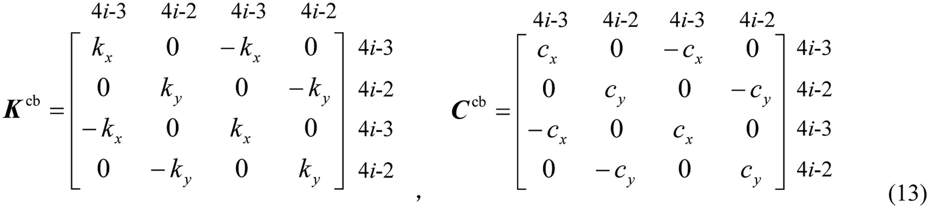
Dual rotor-casing matrix
Based on the idea of finite element method, the dual rotor-casing coupling system is modeled using MATLAB software. The two nodes spatial beam element is adopted to establish the model of the rotating shafts. For ordinary spatial beam element, each node has six degrees of freedom, which are translation along and rotation around the x-, y-, and z-directions, respectively. The element is shown in Figure 2, where x
A
, y
A
, z
A
, x
B
, y
B
, and z
B
are translations along x-, y-, and z-directions while θ
Ax
, θ
Ay
, θ
Az
, θ
Bx
, θ
By
, and θ
Bz
are rotations around x-, y- and z-directions for nodes A and B, respectively. Finite element model of shaft unit.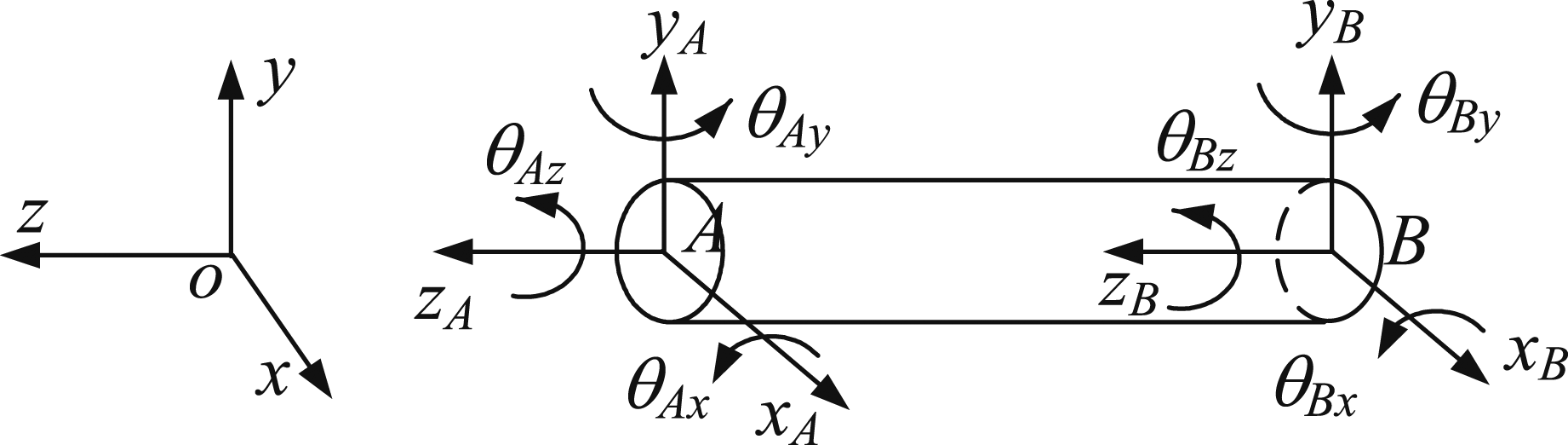
Without considering the translation along and rotation around the z- direction, the degree of freedom of the beam element is

The formula of element mass matrix 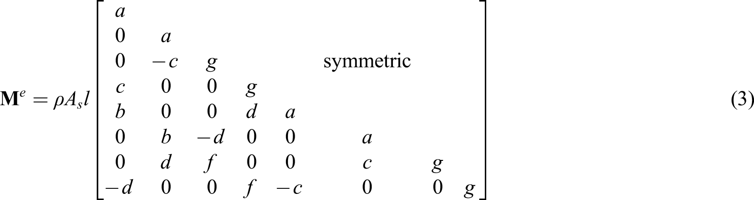
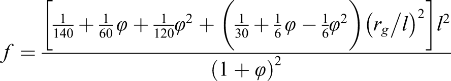
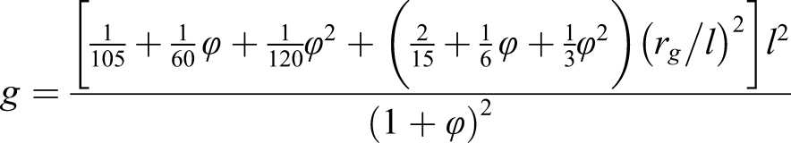
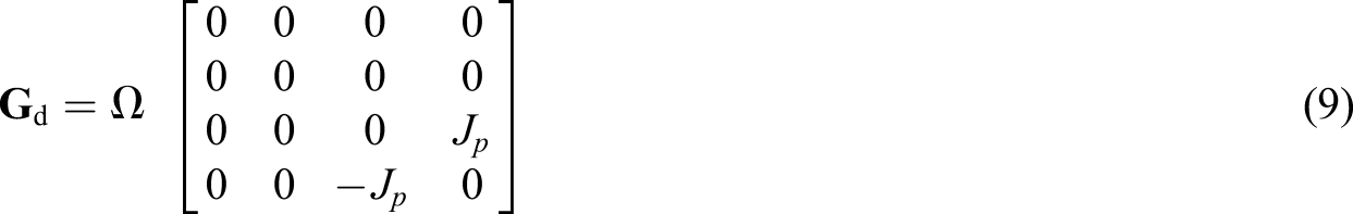
The formula of element gyroscopic matrix 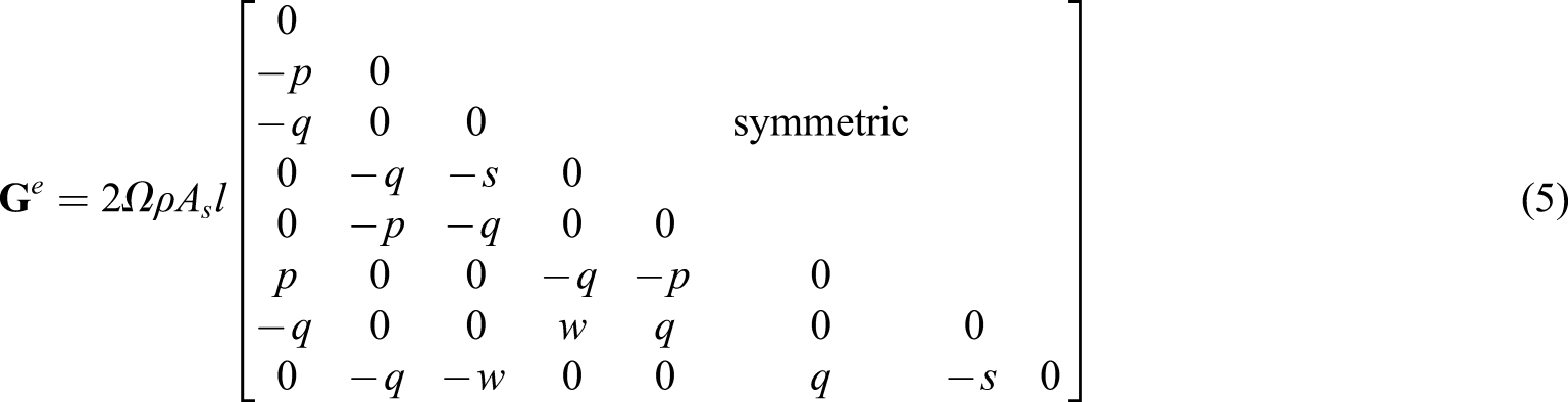
The linear spring-damping model is chosen for describing the dynamic behavior of the bearing. The element stiffness matrix and damping matrix of rotor-casing and casing-foundation supports are denoted by 
The lumped mass model is used for the disk. The specific expressions of the element mass matrix 
Matrix assembling of dual rotor-casing system
The general differential equations of motion for dual rotor-casing system are given by
39


The assembling of stiffness matrix of the dual rotor-casing coupling system Schematic diagram of assembled stiffness matrix for dual rotor-casing coupling system.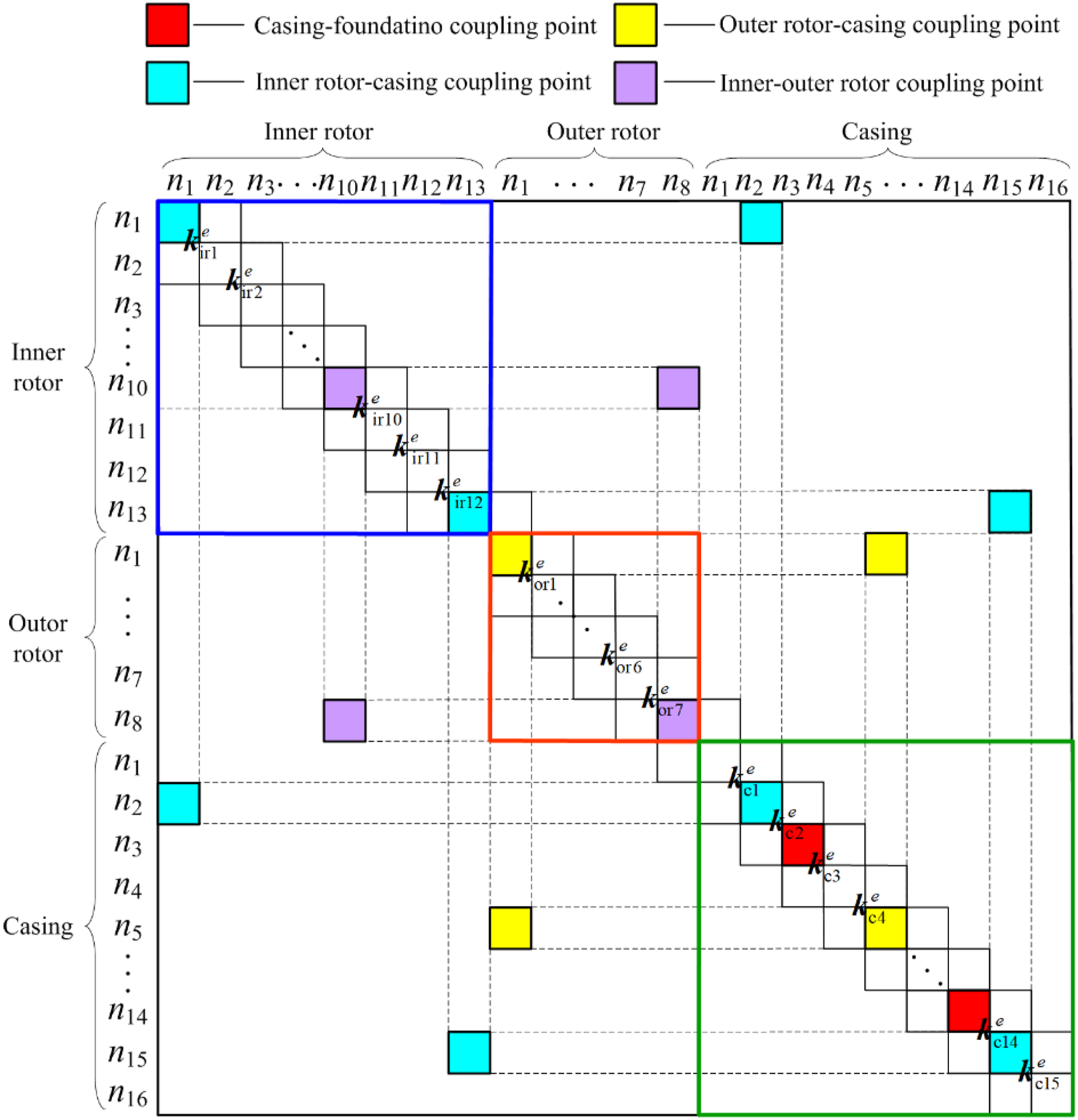
Assuming that the intershaft bearing is located at the i-th node of the inner rotor and the j-th node of the outer rotor. The expressions of the stiffness matrix 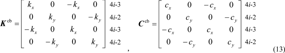
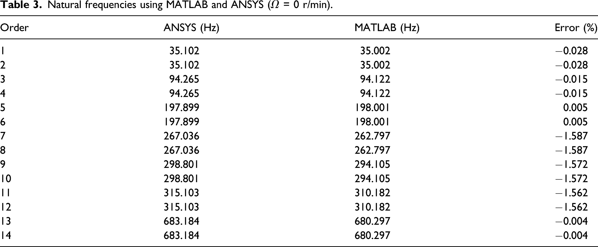
Model verification
Natural frequencies using MATLAB and ANSYS (Ω = 0 r/min).
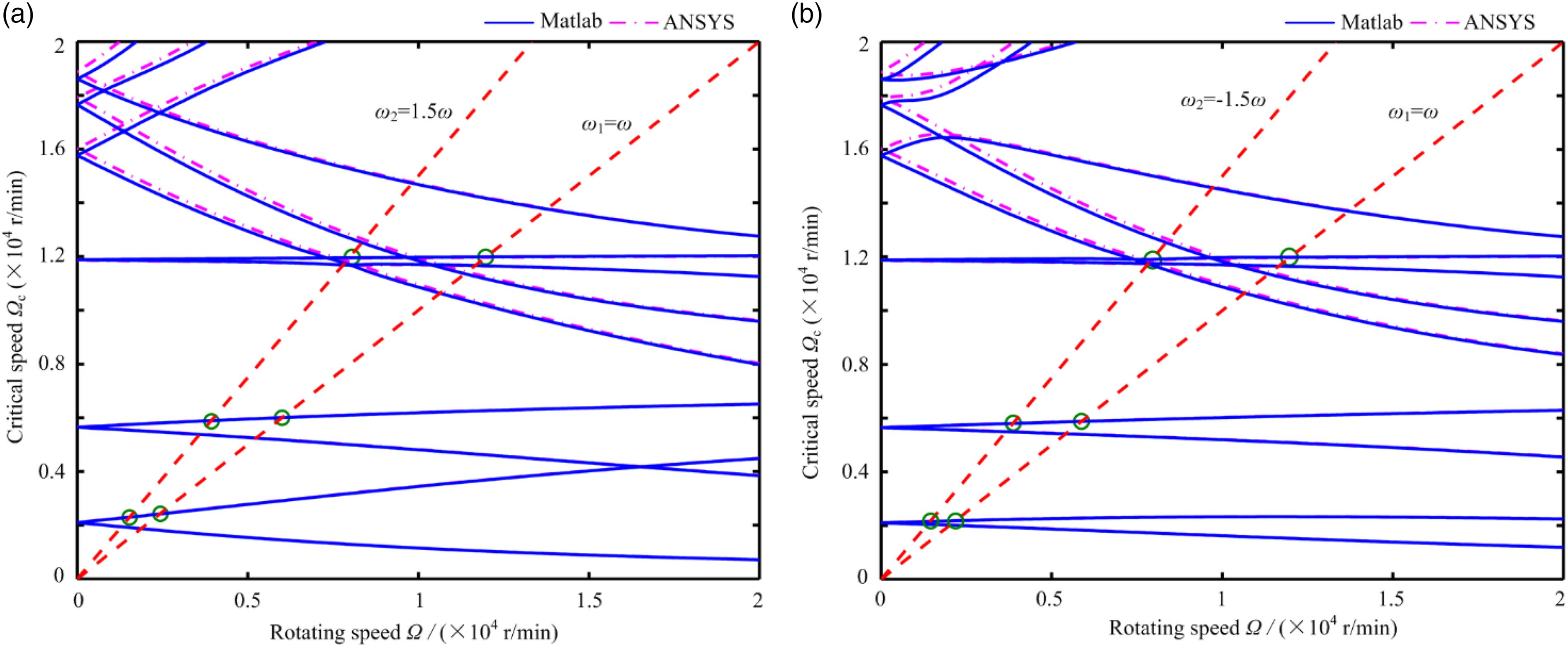
Figures 4(a),(b) are Campbell diagrams of the dual rotor-casing system under the co-rotation and counter-rotation conditions. It can be found that: (1) The dynamic frequency lines calculated by MATLAB are basically consistent with those computed by ANSYS, and the first three order forward and backward whirl frequencies are in good agreement, which shows the validity and feasibility of the model established in this article. (2) With the increase of the rotating speed, the counter-rotation weakens the influence of the gyroscope torque more significantly. In Figure 4(b), the distinctions of the forward and backward precession frequencies for each order under counter-rotation condition are obviously smaller than those under co-rotation, that is the reason why the counter-rotation dual rotor system is more widely used in the aeroengine. Campbell diagram of dual rotor-casing system:
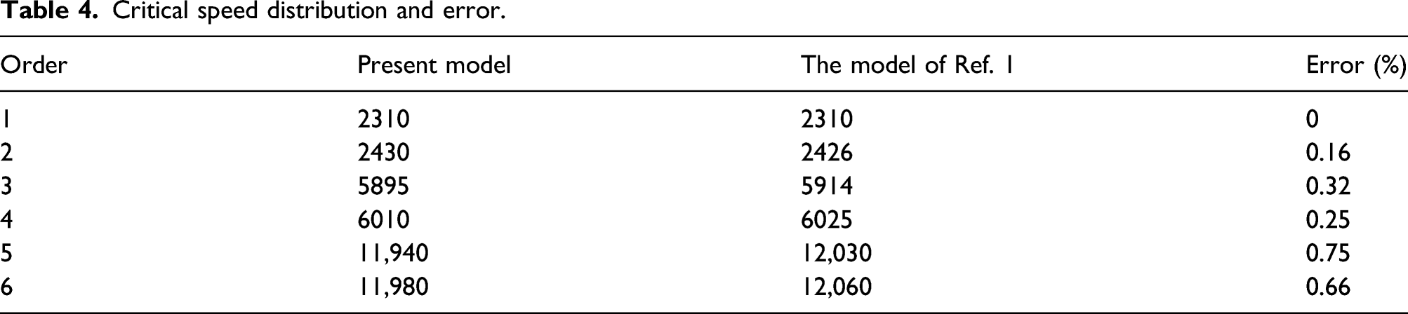
The critical speed diagram of the dual rotor under co-rotation is shown in Figure 5. The solid line and dotted line in the diagram represent the critical speeds under the excitation applied on the low-pressure rotor and on the high-pressure rotor, respectively. The intersection points of the curves with the dash-dotted line, implying the condition that η = 1.5, numbered as 1, 2, 3, 4, 5, and 6, are the critical speeds of the dual rotor-casing system during the acceleration process. The results agree well with those in Ref.,
1
and the maximum error is only 0.75% (see Table 4). Critical speed diagram using the model of Ref.
1
Critical speed distribution and error.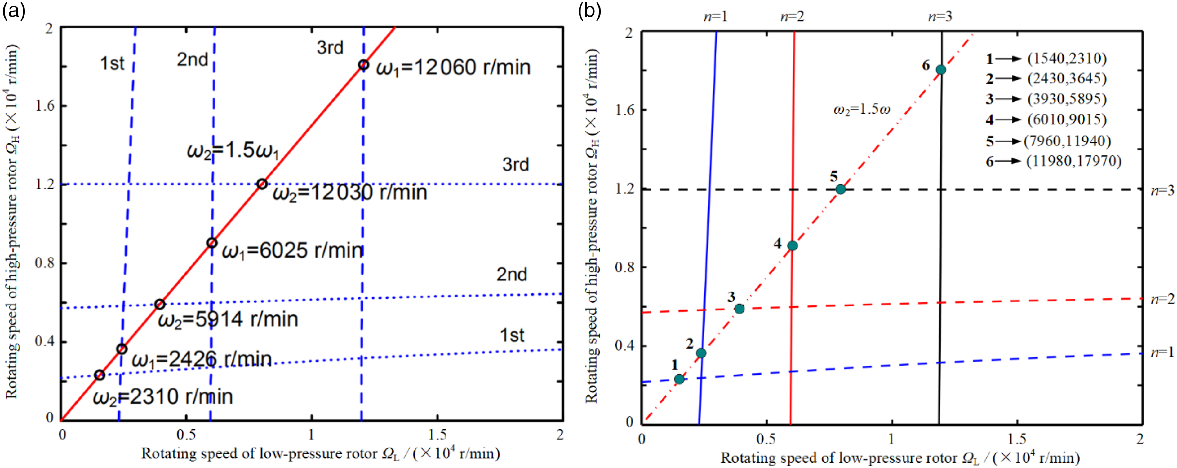
In order to further validate the accuracy of the present model, the transient displacements of the center of Disk 4 are studied and compared with those in Ref.
1
under the exponential law Ω = 10,000 [1−exp (−1.05 t)] rpm and the linear law Ω = Transient displacements of the center of Disk 4 using the model of Ref.
1
under the linear law 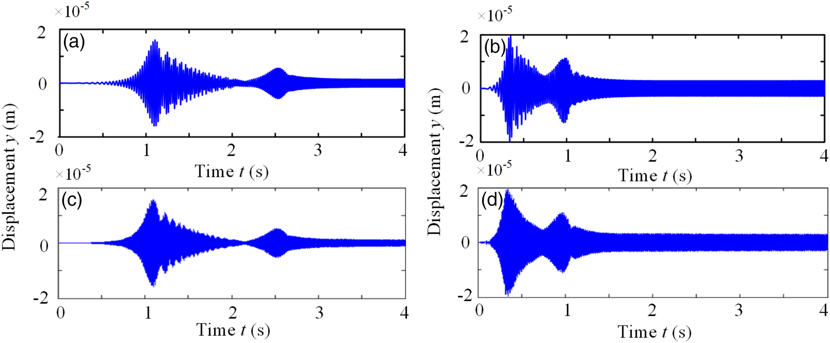
Rubbing analysis of dual rotor-casing system
Newmark-β method is adopted to solve the response of dual rotor-casing rubbing. With the characteristics of high efficiency and numerical stability, the differential form of Newmark-β integration method is
1

By substituting equation (15) into equation (10), we can get
Equation (16) can be simplified as
When the Newmark integral parameters meet the following conditions, the result of the equation will be unconditionally stable
Local rubbing force model
Figure 7 is a simplified local-rubbing schematic of dual rotor-casing system. When the system is in a static state, the rotor center is located at Od, and the casing center Oc coincides with the coordinate origin O. Rd and Rc are radius of the disk and inner-wall of the casing, respectively. The static parallel misalignment e between the two centers is preset before rubbing. For calculation convenience, the condition that xm = ym is used. The minimum clearance c between the rotor and the casing is expressed as Local-rubbing schematic of dual rotor-casing system.
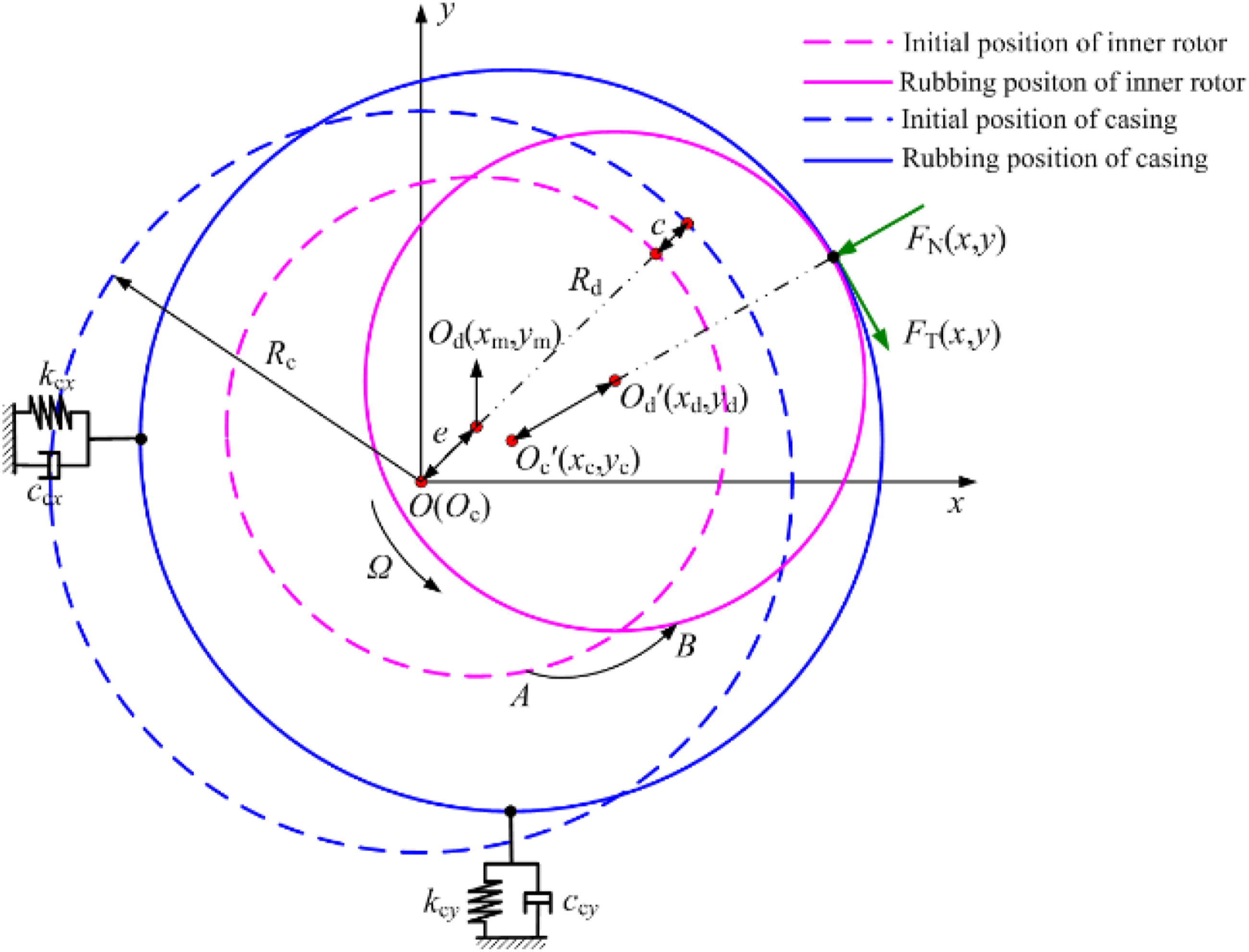
In the actual working process, due to the existence of installation error, rub impact, and other fault factors, the rotor center and casing center deviate from the original position, located at Od’ and Oc’, respectively. In this case, the radial relative displacement ξ is given by
When ξ < e + c, there is no rubbing; when ξ ≥ e + c, rubbing phenomenon occurs. Setting δc as the penetration depth between rotor and casing, then
Normal and tangential rubbing forces can be written as
Effect of rotating speed on rubbing response
Node 3 on the inner rotor (at the location of left disk) and the node 25 on the casing are set as the rub-impact points. The specific simulation parameters are as follows: the unbalance magnitude of four disks fu = 156 × 10−6 kg m, speed ratio η = ω2/ω1 = −1.2, initial clearance c = 1×10⁻⁴ m, rubbing stiffness kr = 8 × 10⁶ N/m, the static parallel misalignment e = 8 × 10⁻⁵ m, friction coefficient μ = 0.3, and model damping ratio ξ1 = ξ2 = 0.08.
Figure 8 is a three-dimensional spectrum of rub-impact response of the center of disk 1 at different speeds. Here, the operating speed range is 800∼5800 r/min. While the rotating speed range is 800∼2000 r/min, the number of times that rubbing occurs is relatively fewer. The spectrum mainly shows the corresponding rotating frequency of inner and outer rotors, denoted by f1 and f2, respectively. When the rotating speed Ω = 1700 r/min, amplitude amplification phenomenon occurs on the spectrum line corresponding to the outer rotor, this is because the rotating frequency of the outer rotor arouses the first natural frequency of the system. When the rotating speed reaches the range of 2000∼4000 r/min, besides rotating frequencies, frequency multiplication, frequency division, and the combination frequency of the rotating frequencies appear, such as f2 − f1, 1/2f2, 2f1 − f2, 2f1, f1 + f2, and 2f2. When the rotating speed of inner rotor Ω=2300 r/min, the first natural frequency of the system is excited and obvious amplitude amplification phenomenon occurs (point B in Figure 8). When the rotating speed reaches the range of 4000∼5800 r/min, the rubbing between the rotor and the casing becomes more vigorous, and some high frequency components and combined frequency appear. The amplitudes are increasing, and the frequency multiplication components are much more significant. The second-order natural frequencies of the system are excited by the inner and outer rotors (points C and D in Figure 8), and the amplitude amplification phenomenon is more highlighted under the corresponding speed. Three-dimensional spectrum of inner rotor rubbing under different rotating speeds.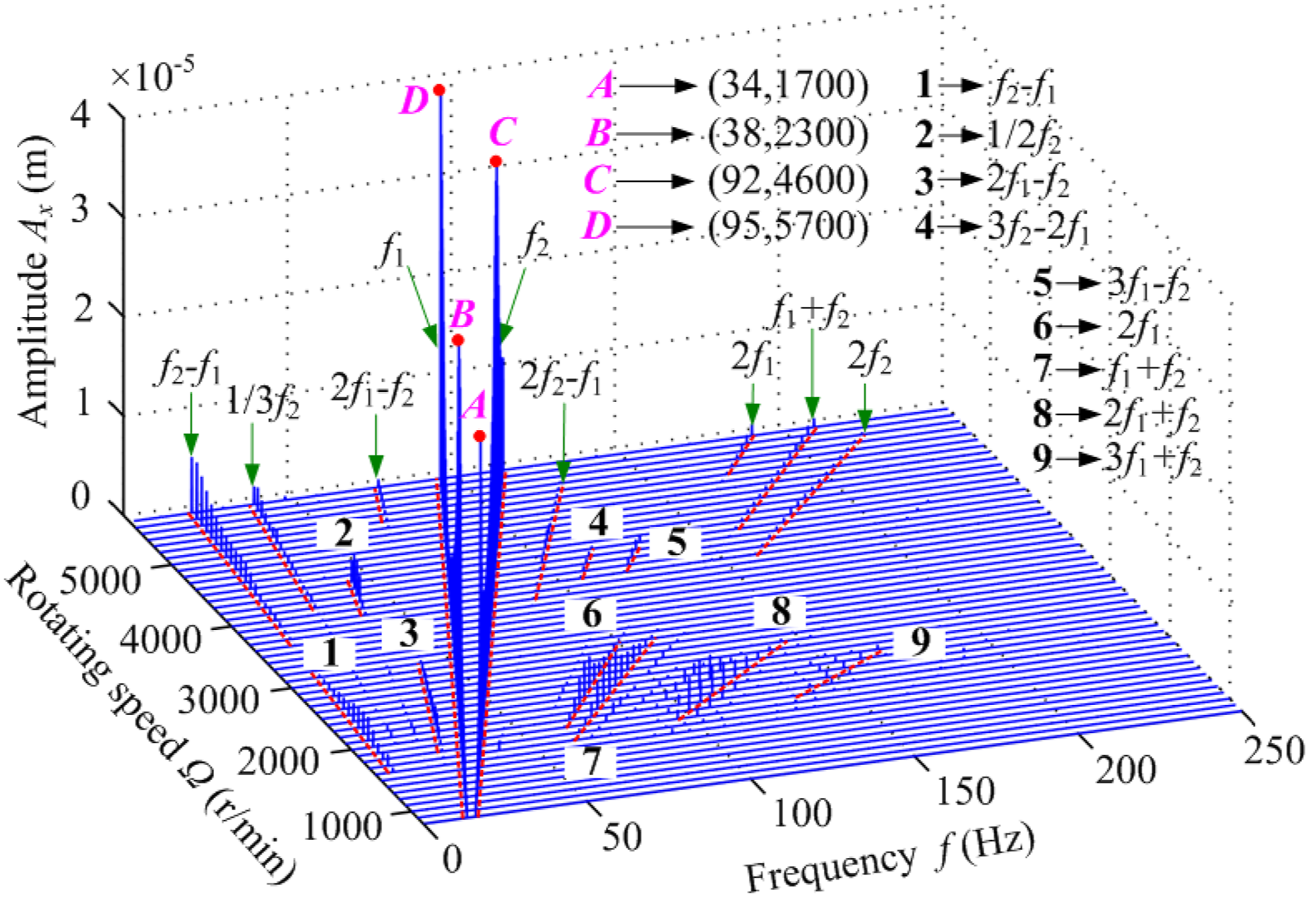
Effect of speed ratio on rubbing response
Figure 9 is a three-dimensional spectrum of rub-impact response under different speed ratios. It can be seen from the figure that the spectrum lines present a capital “N” shape, and the high-frequency component in the spectrum is not prominent. There are mainly five spectral lines, corresponding to the frequencies of f2 − f1, f1, f2, 2f1, and f1 + f2. Under the condition that η = −1, the rotating speeds of inner and outer rotors are in the same value, resulting in the amplitude superposition at the corresponding spectral lines, so that the amplitude at point B in the figure is significantly higher than those of other places. Furthermore, amplitude amplifications occur at points A and C. This is because the combined frequency f2 − f1 excites the first natural frequency of the system and resonance occurs at point A. What is more, the rotating frequency of outer rotor f2 excites the second natural frequency of the system at point C. With the increase of the absolute value of the speed ratio η, amplitude variations corresponding to the rotating frequency of inner rotor are not notable, while those corresponding to outer rotor appear an increasing trend. It can be found that the factors which cause the resonance of the system are rather complicated. On the one hand, both of the inner and outer rotor rotating frequencies can excite the natural frequencies of the system. Due to the effect of speed ratio, the excitations of natural frequencies by outer rotor are prior to those by inner rotor (point C in the figure); on the other hand, under the fixed speed condition, different values of speed ratio arouse the resonance of the system at different combination frequencies. Here, the resonance peaks are not only limited to the rotating frequencies of the inner and outer rotors but also located at combined frequency points (point A in the figure). Three-dimensional spectrum of inner rotor rubbing under different speed ratios.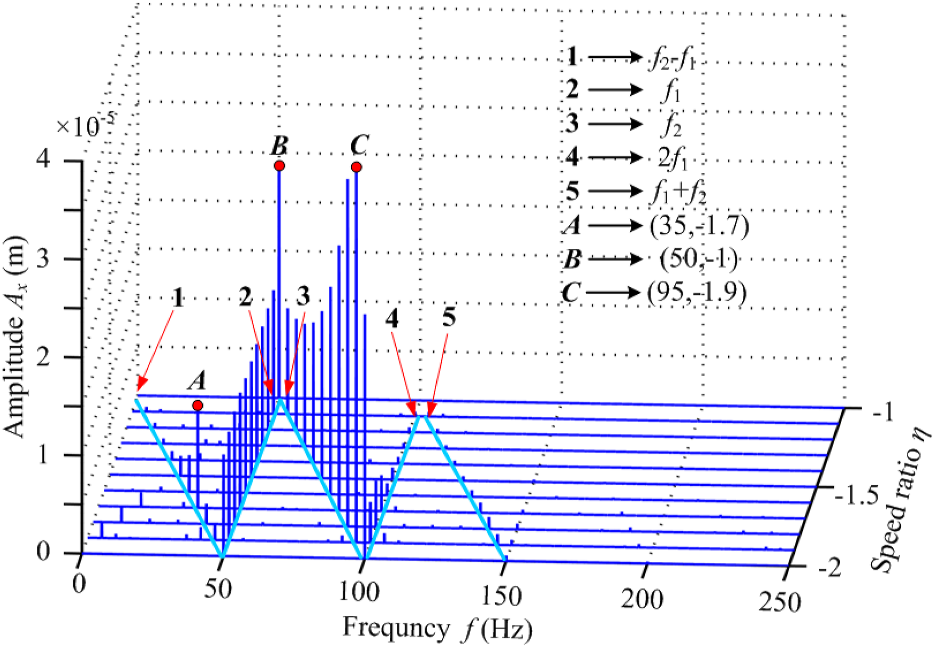
The influence of unbalanced force on the response of dual rotor system can be intuitively reflected by axis orbit diagram under co-rotation and counter-rotation conditions. The rotating speed is set as Ω = 2300 r/min, and Figures 10, 11 show the axis orbit diagram of node 3 on the inner rotor under counter-rotation and co-rotation conditions, respectively. It can be seen that the axis orbit under counter-rotation condition is simpler and more regular than under co-rotating condition. Most of the axis orbits under counter-rotation condition appear “petal” shape, and the number of “petals” is different under different speed ratios; while axis orbits under co-rotating condition appear the shape of big circle covering small circle. By comparing with the former, the axis orbits are much more complex. At the condition that η = 1 or η = −1, the axis orbits under counter-rotation condition present the shape of inclined ellipses, while those under co-rotation condition present the shape of circles. At the condition that η = 1.5 or η = −1.5, there are “sudden changes” in the axis orbits of the inner rotor, at this time, period-2 motion occurs in both cases. Rotor orbit of counter-rotation dual-rotor under different speed ratios. Rotor orbit of co-rotation dual-rotor under different speed ratios.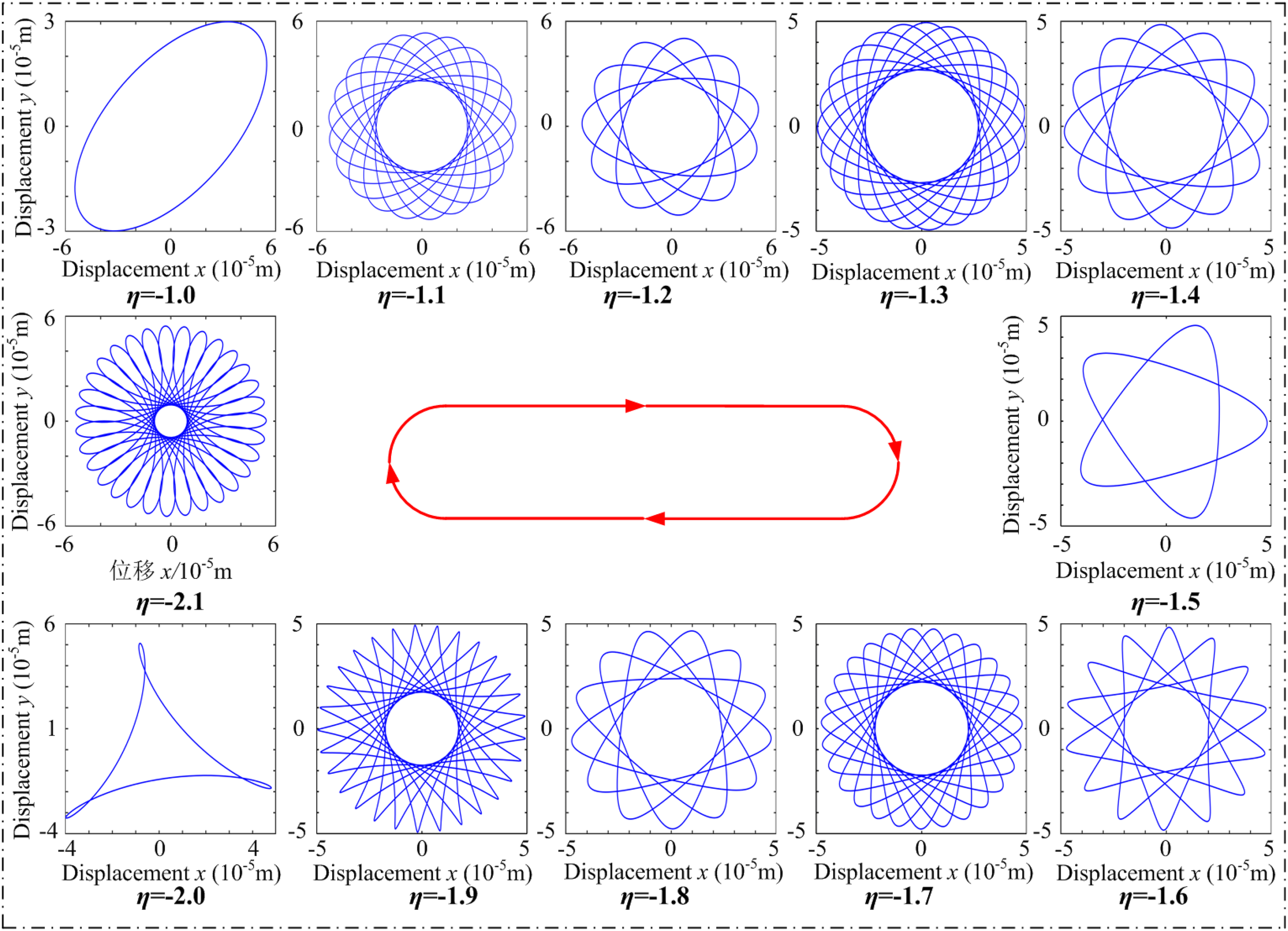
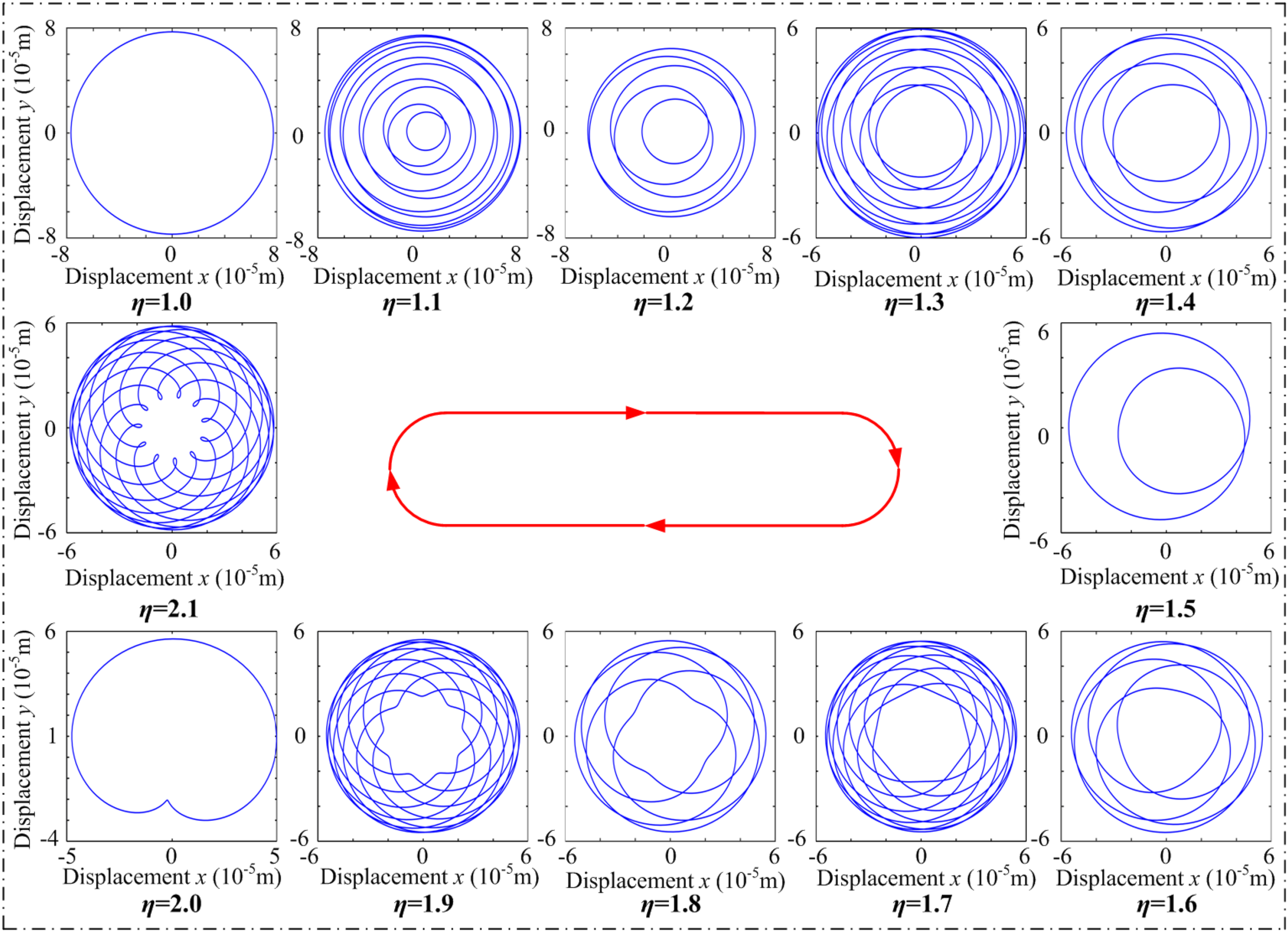
In addition, the axis orbits at the condition that 10η is odd are obviously more complex than those at the condition that 10η is even. The inner and outer rotors under counter-rotation condition rotate at reverse directions, that weakens the gyroscopic effect and reduces the amplitude of the unbalanced response, so that the counter-rotation dual rotor system is more stable than the co-rotation dual rotor system. It can also be seen from the comparison of the two figures. Therefore, most scholars focus on the dynamic characteristics of the counter-rotating dual rotor system.
Figure 12 is a bifurcation diagram of the displacement of the inner rotor under different speed ratios with rubbing fault. The region (−2, −1) is selected as the speed ratio range, and the interval is set as −0.02. The rotating speed is Ω = 3000 r/min. Different from the traditional single rotor system, the response mainly carries out period-2, period-5, and period-10 motions when only one digit after the decimal point of the speed ratio is considered, such as −1.5, −1.7, and −1.9. When the speed ratios are integers, such as η = −1 and η = −2 in the diagram, the response carries out single period motion. When two decimals are considered, the response appears multi-period motions. It shows that the speed ratio has a great influence on the periodic motion of the response. Bifurcation diagram of inner rotor under different speed ratios.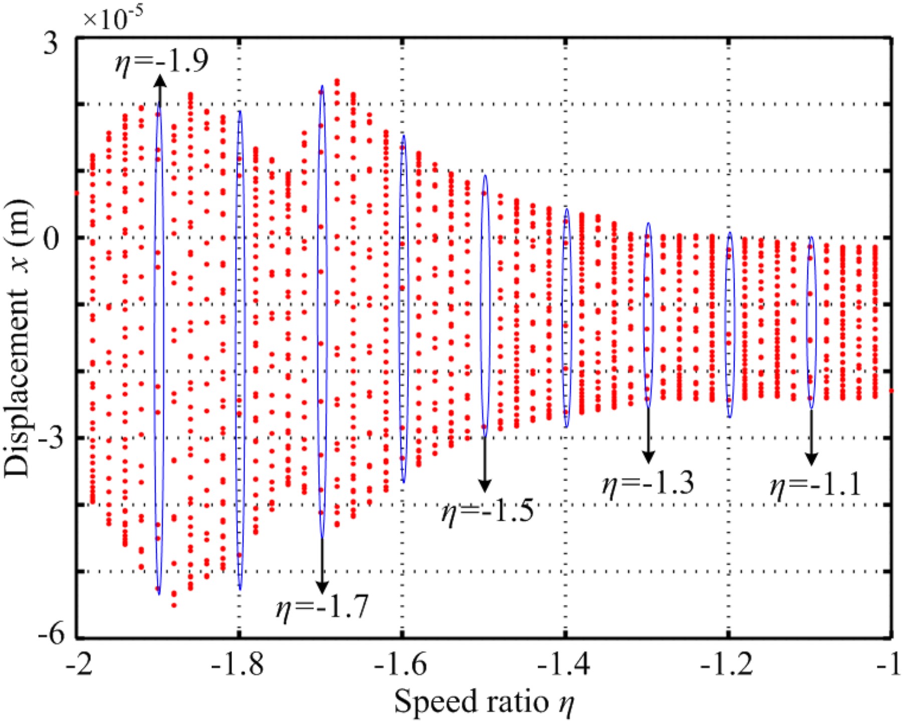
The two characteristic speed ratios η = −1.5 and η = −1.7 corresponding to period 2 and period 10 motions are selected to study the rubbing responses. Figure 13 shows the rubbing responses of node 3 on inner rotor and node 25 on the casing (η = −1.5). It can be seen that the rubbing level is relatively lower. The wave clipping phenomenon of the inner rotor is not significant, also there is almost no change at response amplitude of the casing before and after rub impact, that can be proved by the axis orbit diagram. During the rubbing process, the rotating frequency of inner rotor f1 and outer rotor f2 and the frequency component of f2 − f1 are mainly excited. There are many high frequency components in the response of the casing, but the amplitudes are very small. It can be seen from the spectrum in Figure 13(b) that the influence of the rotating frequency of outer rotor f2 on the response of the casing is much larger than that of inner rotor f1. System rubbing responses with η = −1.5: 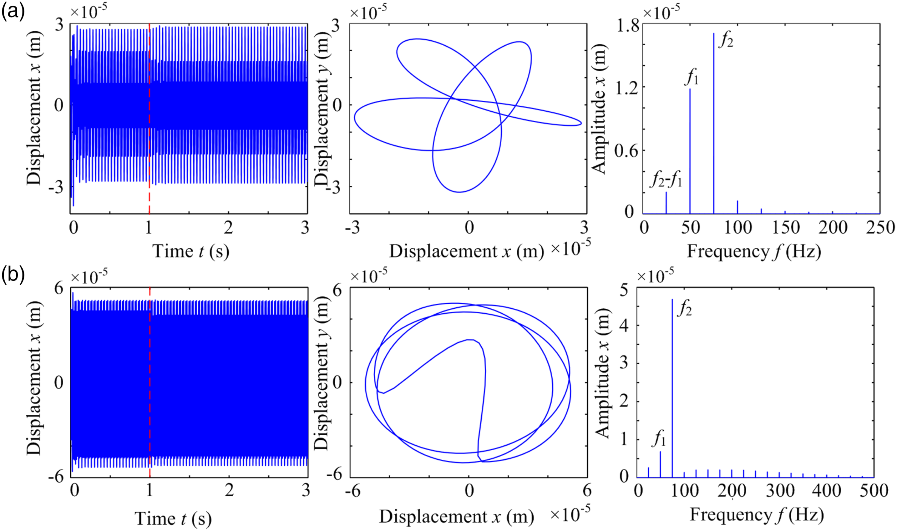
Figure 14 shows the rub-impact response of the inner rotor and the casing (η = −1.7). Wave clipping phenomenon occurs after rubbing, that is also reflected in the axis orbit diagrams. The amplitude amplification phenomenon appears at combined frequency f2 − f1=35 Hz, which is close to the first natural frequency of the system. A lot of combined frequencies are excited on the frequency spectrum of the inner rotor, such as 2f1 − f2, f2 − f1 and f1 + f2. System rubbing responses with η = −1.7: 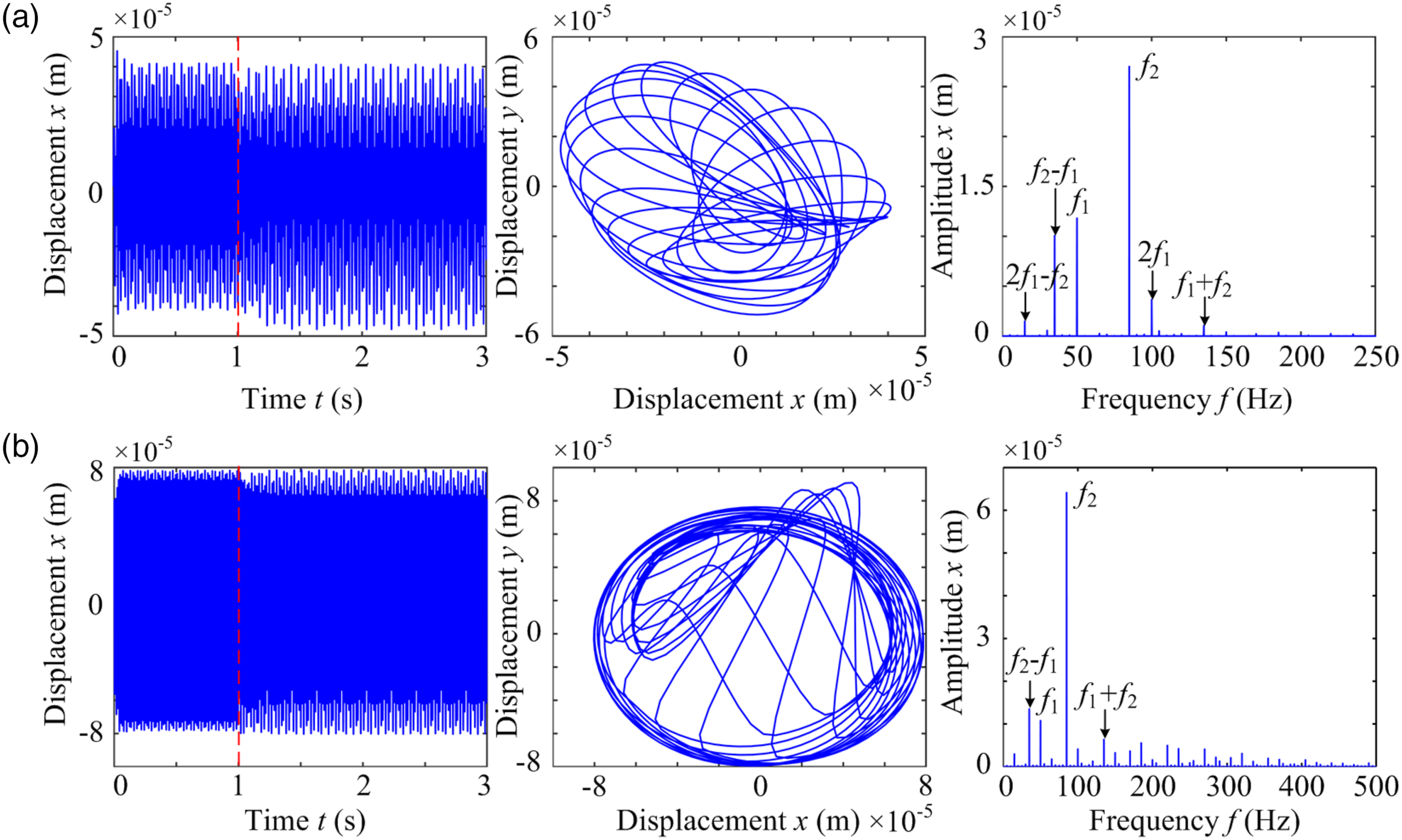
Figure 15 shows the normal rubbing forces under different speed ratios. The response presents period-2 motion, period-10 motion, and period-10 motion at the condition that η = −1.5, η = −1.7, and η = −1.9, respectively. With the increase of the absolute value of the speed ratio, the whirl radius of the outer rotor and the normal rubbing forces increase dramatically. Normal rubbing force of casing node 25 under different speed ratios: 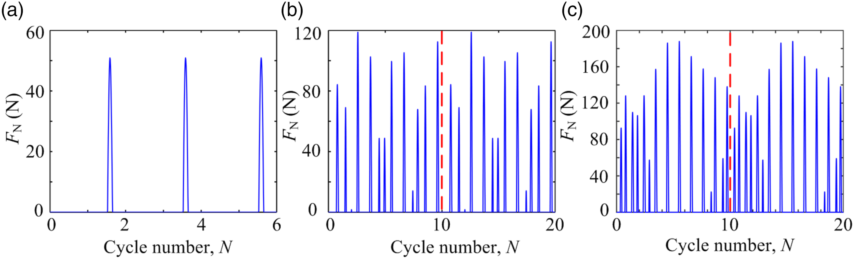
Effect of mass unbalance on rubbing response
The impact of mass unbalance magnitudes on the rubbing response is discussed in this section. The specific simulation parameters are as follows: the rotating speed Ω 2300 rpm, speed ratio η = ω2/ω1 = −1.2, initial clearance c = 1 × 10⁻⁴ m, rubbing stiffness kr = 8 × 10⁶ N/m, the static parallel misalignment e = 8 × 10⁻⁵ m, friction coefficient μ = 0.3, and model damping ratio ξ1 = ξ2 = 0.08.
Figures 16, 17 show the rubbing response of node 3 on the inner rotor under the condition that mass unbalance magnitude fu = 200 × 10−6 kg m and fu = 550 × 10−6 kg m, respectively. It can be seen from the figure that the whirl trajectory values and response amplitudes of the inner rotor increase with the growth of mass unbalance magnitude. When the rubbing occurs, the wave clipping phenomenon of the inner rotor becomes more significant under higher value of mass unbalance magnitude. Due to the coupling effect of the inner rotor, outer rotor, and the casing, the axis orbit of the inner rotor becomes more complicated, and the spectrum amplitude is larger with the increase of the mass unbalance magnitude. The response frequency components mainly concentrate on the rotating frequency of the inner rotor f1, the outer rotor f2, combined frequency f2 − f1, and multiple rotating frequencies. System rubbing responses with fu = 200 × 10−6 kg m: System rubbing responses with fu = 550 × 10−6 kg m: 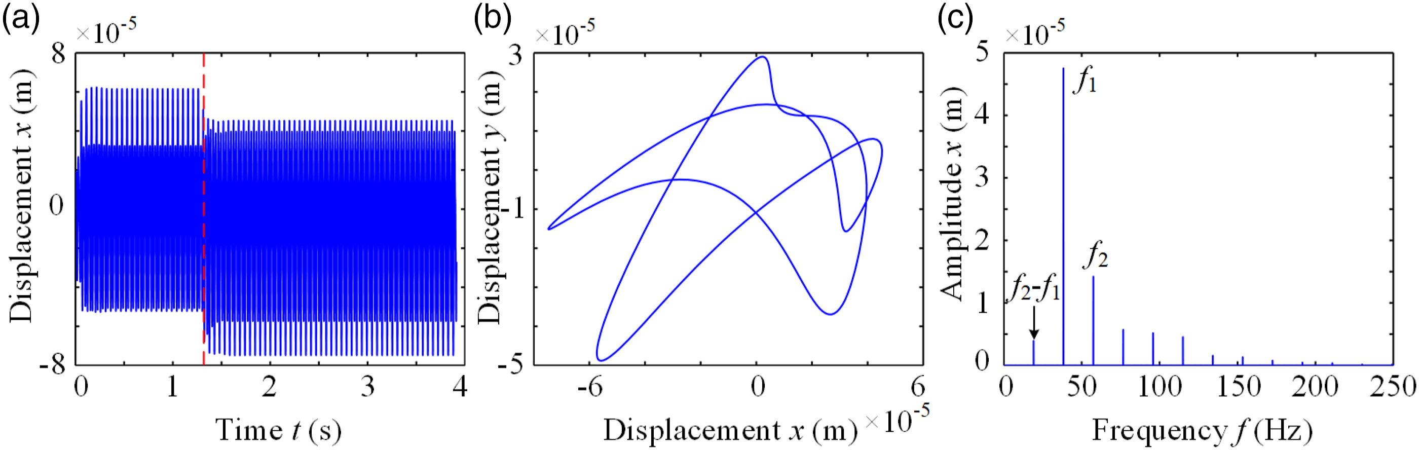
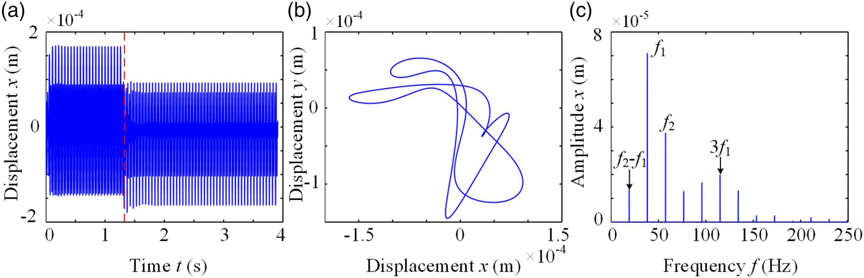
Figure 18 shows the response of node 3 on the inner rotor under the condition that mass unbalance magnitude fu = 550 × 10−6 kg m without considering the impact of rubbing. The response of the inner rotor presents cyclostationary state during the time-domain history under the condition that no rubbing occurs [see Figure 18(a)]. In the rotor orbit as shown in Figure 18(b), the order of magnitude is the same as that in Figure 17(b), but in a more regular form. The frequency components are concentrated on the rotating frequency of the inner rotor f1 and the outer rotor f2, without any combined frequencies or multiple frequency components [see Figure 18(c)]. System responses with fu = 200 × 10−6 kg m neglecting the rubbing impact: 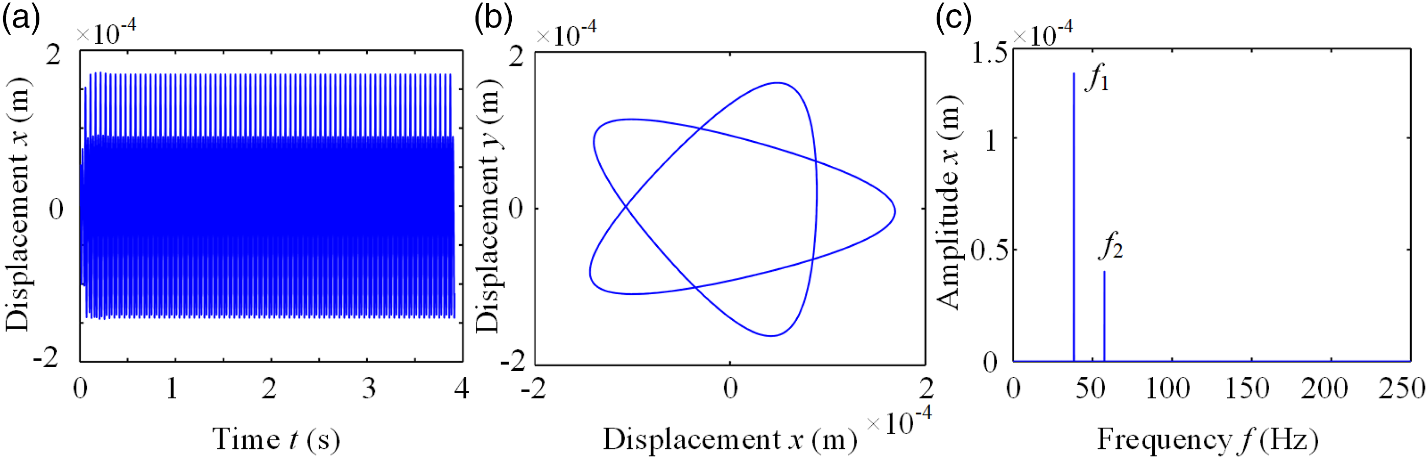
Conclusion
The model of dual rotor-casing coupling system is established, and then the local rubbing response is analyzed in this article. The effects of rotating speed and speed ratio on rub-impact response are studied. Some detailed conclusions are listed as follows: (1) The dynamic frequency curves computed by the model in this article are in good agreement with the results in references and calculated by FEM method, that shows the validity and feasibility of the model established in this article. (2) The counter-rotation weakens the influence of the gyroscope torque, that is the reason why the counter-rotation dual rotor system is more widely used in the aeroengine. (3) As the rotating speed increases, the rubbing between the rotor and the casing becomes more vigorous, and some high frequency components and combined frequency appear. Meanwhile, the frequency multiplication components are more significant. (4) Speed ratio has a great influence on the periodic motion of the system. In addition, with the increase of the absolute value of the speed ratio, the whirl radius of the outer rotor and the normal rubbing force increase dramatically.
Footnotes
Declaration of conflicting interests
The author(s) declared no potential conflicts of interest with respect to the research, authorship, and/or publication of this article.
Funding
The author(s) disclosed receipt of the following financial support for the research, authorship, and/or publication of this article: This project is supported by the National defense basic scientific research funding project (Grant No. JCKY2018414C015, Mr Honggen Zhou) and the National Natural Science Foundation of China (Grant No. 51605204, Mr Honggen Zhou).
Data availability statement
The data used to support the findings of this study are available from the corresponding author upon request.