
Abstract
Simple and light-weighted quasi-zero stiffness (QZS) isolators can be designed based on nonlinear and negative stiffness generated by the snap-through effect of bistable structures. Traditionally, the snap-through force of the bistable structure is limited which makes the weight which can be isolated based on this mechanism very low. This paper investigates increasing loading capacity of this kind of isolator by using an optimized and varying sectional profile. Numerical models were derived for the bistable structures with variable sectional distributions. Optimized sections’ alignment of the bistable beam was derived based on the numerical model which was consequently validated by experimental results. Influences of the bistable beams with a variable section on nonlinear stiffness characteristics and performance of the isolator were at last investigated with the harmonic balance method.
Introduction and background
In recent years, isolators with quasi-zero stiffness (QZS) have attracted great research attention as this kind of isolator can efficiently reduce the dynamic responses of the system from low-frequency excitations, which often makes them desirable in a wide range of engineering practices. 1 Traditionally, these kinds of isolators are composed of elements with different and often nonlinear stiffness characteristics. These elements are designed so that overall stiffness of the system was close to zero when imposed with the gravity load of the isolating mass. 2 Researchers are continuously exploring new and better mechanisms to achieve the QZS, including the folded pendulum or X-pendulum,3–5 magnetic ant-springs,2,6,7 anti-springs based on geometric nonlinearity,8–15 Euler buckling beams,16,17 and the bistable structures. 18
In addition to the requirement of the stiffness and loading capacity, there are often limitations on overall weight of the isolator, especially when the isolator is used in aerospace engineering. In these cases, isolators based on bistable and multistable structures are often advantageous as these structures can provide nonlinear and negative stiffness with a unitary structure. 18 A curved beam which is axially restrained at the two ends is probably the simplest bistable structure which has two opposing stable positions around the chord of the curved beam. Qiu et al. 19 derived mechanical model for the double-curved bistable beams. Chen et al. 20 investigated using the bistable beams in parallel to design actuators with multistable positions. Shaw et al. 18 investigated using bistable plates to generate negative stiffness which allows to design QZS isolators.
QZS isolators based on bistable structure require no hinges or pre-stressed springs, which often allow these isolators to be very light-weighted.19,20 On the other hand, QZS isolators based on the bistable structure often have limited loading capacity and initial stiffness. This is mainly due to the fact that in order to exhibit a bistable behavior, large extreme strains are expected in the bistable structure which limits heights of the bistable beam and correspondingly its initial stiffness and peak strength.21,22 Strengths and stiffness of the bistable beams can be increased by using variable cross-sections in these structures. Assuming rigid middle sections of a bistable beam, Haghpanah et al. 21 deduced solutions for bistable beams with a thinner section in the two ends and found that strengths of the beam were significantly increased. Zhang et al. 23 deduced a more widely suited solution for the bistable beam and performed an optimization in terms of its peak strength. With similar extreme strains, bistable beams with variable sections were found to have by most 120% larger snap-through forces, 145% initial stiffness, and 230% negative stiffness compared with the beams with similar cross-sections which are all very desirable for QZS dampers. Bistable beams with variable cross-sections also have richer mechanical behavior in terms of the negative stiffness and displacement corresponding to maximum and minimal strengths which allow engineers to design QZS isolators for different scenarios. However, there currently lack systematic investigations regarding the optimized sectional alignment for QZS isolators with bistable beams with variable sections. A design method is also required.
This paper investigates QZS isolators with bistable beams with variable cross-sections. Relations between the geometric parameter of the beam and initial stiffness, loading capacity and static deformation of the isolator were developed based on a theoretical solution. Influences of the nonlinear stiffness of the bistable beams on transmissivity of the isolation system were investigated using the harmonic balance method. Also, tests were performed for the bistable beams based on the proposed methodology for validation.
Mechanical model of beams with variable cross-section
Force–displacement response and maximum strain
Calculating force–displacement relation of the bistable structures can be difficult due to its significant geometric nonlinearity and many possible stable positions and deformation modes. Additionally, increasing performance of the bistable beams based on the variable section profile requires calculating detailed behavior of the beam with high accuracy and efficiency. For the bistable beams with a rigid middle branch and two ends with reduced sections, Haghpanah et al. 21 proposed an explicit approximate method. However, the method can only be used for a bistable beam with an overwhelmingly strong middle branch. In this study, the chained constrained beam model proposed by Ma et al. 24 is applied with some modifications for considering extreme strains in the beam.
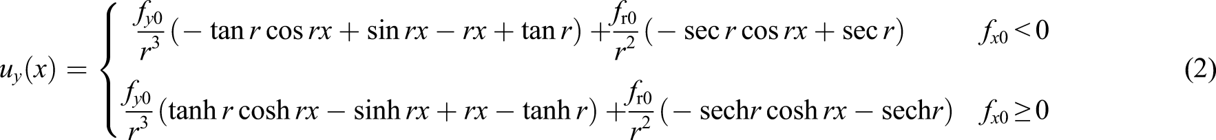
For a cantilever Euler beam shown in Figure 1, the differential equation of the beam considering large deformation can be written as equation (1). The analytical solution to the equation can be given in equation (2) Cantilever beam in large deformation.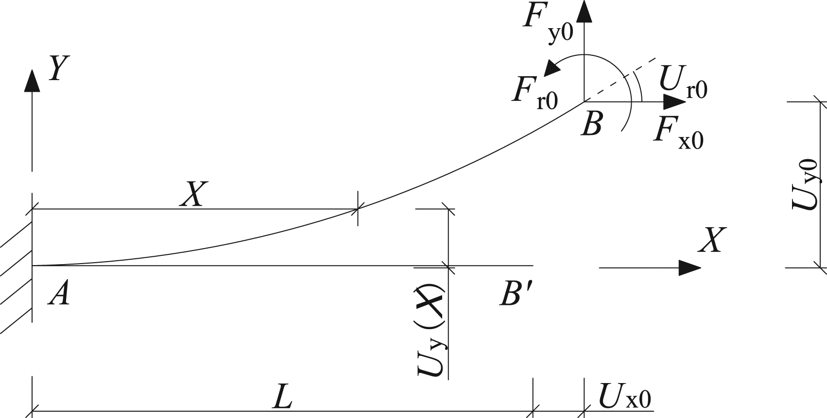


Mechanical behavior of bistable beams with variable section
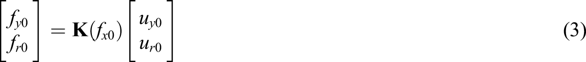
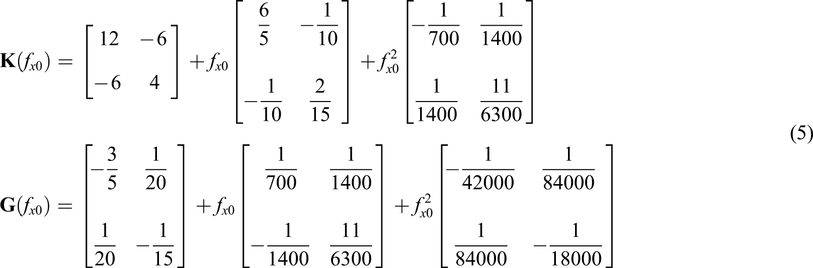
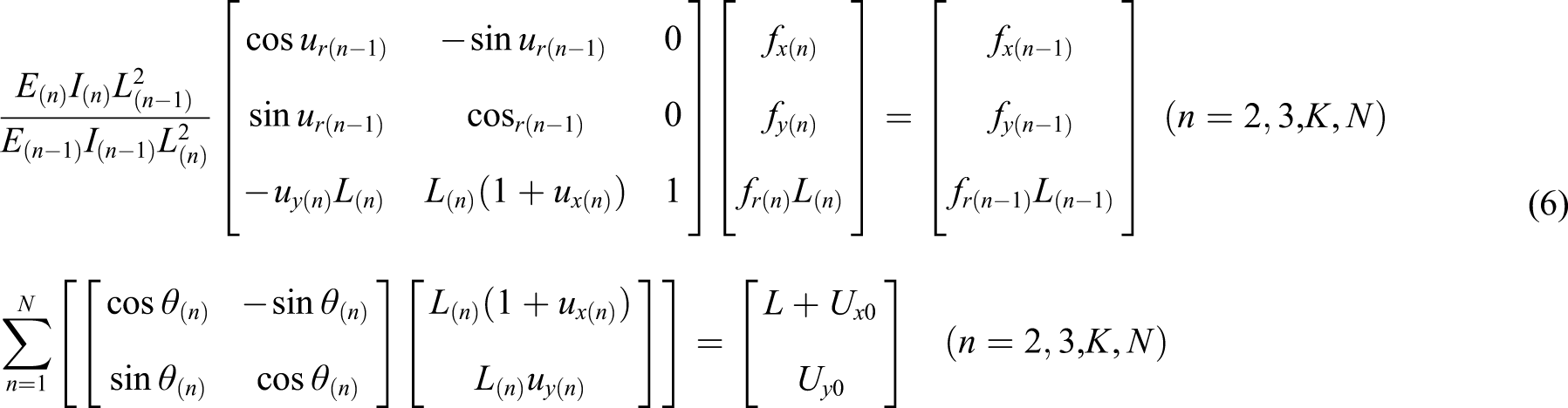
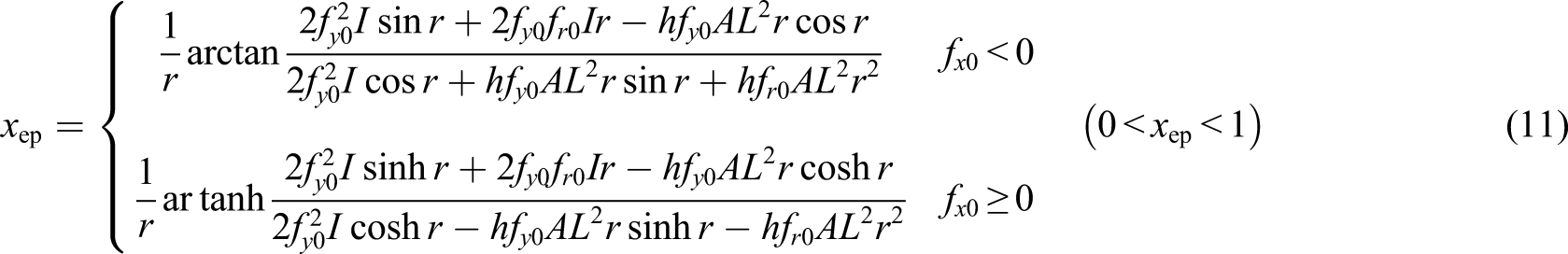
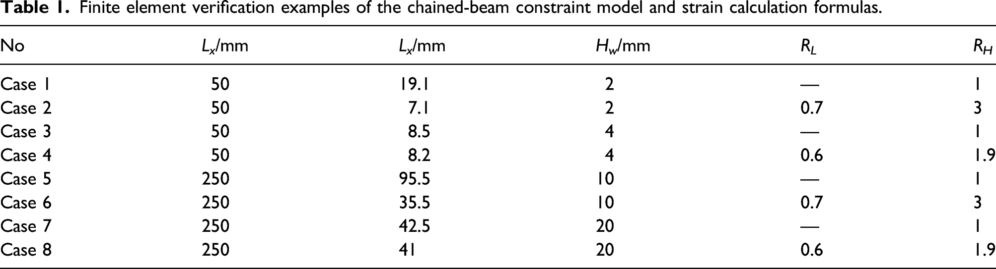
Using the numerical solution, mechanical behavior of bistable beams with variable sections was investigated and compared with beams with uniform sections. In addition to results calculated based on equations (3) to (11), results were calculated from 2-dimensional beam-column element (BE2) from ABAQUS. Four different cases were calculated with two of them having uniform section and the other two with variable section alignment (Figure 2 and Table 1). With similar width and span, the inclined angle and thickness of these beams were different so that the maximum extreme strain of the bistable beams was approximately similar as shown in Figure 3. Geometric details of these cases are summarized in Table 1 (Case 1 to 4), and their force–displacement curves are given in Figure 3. Bistable beam with a variable section. Finite element verification examples of the chained-beam constraint model and strain calculation formulas. Force–displacement curves and extreme strains calculated from the deduced equations (CBCM) compared with the FE models.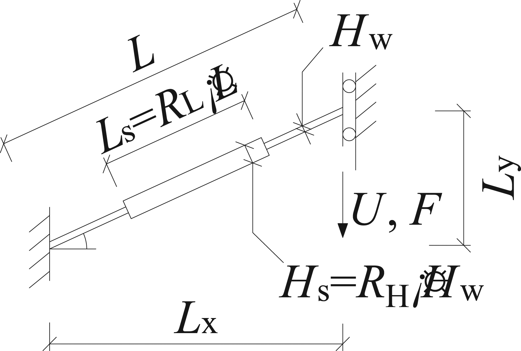
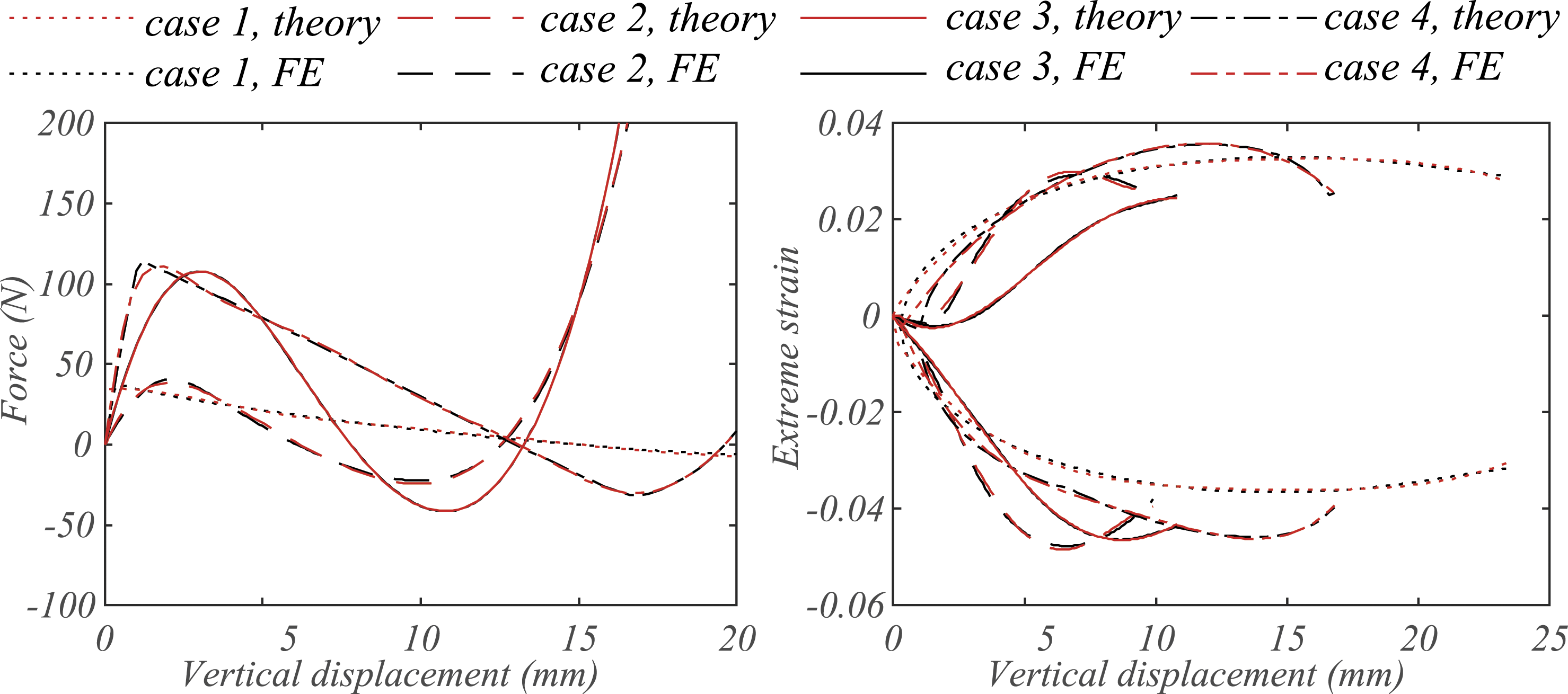
From the figure, it can be seen that bistable beams with variable sections have very different behavior compared with that of uniform sections. Subjected to limitations of the extreme strain, the peak strength in the positive direction were similar for beams with similar thickness. However, with the augmented middle branch and a reduced inclined angle, the displacement corresponding to the peak strength was increased while negative stiffness increased significantly. Also, the curves are slightly different in shape. This is due to the fact that the bistable beams with uniform sections are buckled at the snap-through phenomenon. For QZS isolators based on the bistable beam, the loading capacity comes from both the bistable beam and the linear spring which aims to counter the negative stiffness. Consequently, both increasing negative stiffness and delaying the snap-through phenomenon increase the loading capacity of the isolator, as shown in Figure 4. Performance of the isolator based on bistable beams with variable sections.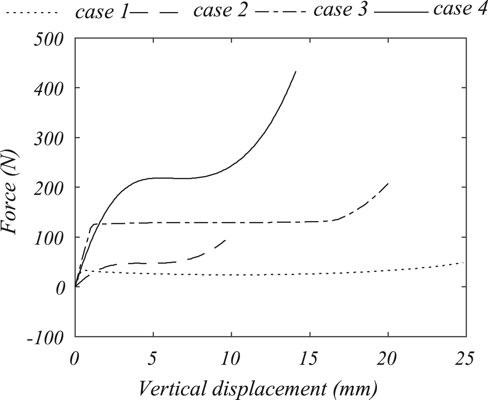
Another interesting feature of the bistable beam is that the beam can be scaled up, while with its stiffness and extreme strain remain the same. This is clear from equations (2) and (6). In the equation, f
x
, f
y
, f
r
are normalized by EI. Influences of the scale-up also cancel out in equation (6). Figure 5 shows the force–displacement and strain–displacement curves of bistable beams in scale as summarized by Case 5 to 8 in Table 1. The force–displacement curves increased to scale, while the strain curves remained similar. Influences of enlarging on performance of the bistable beams.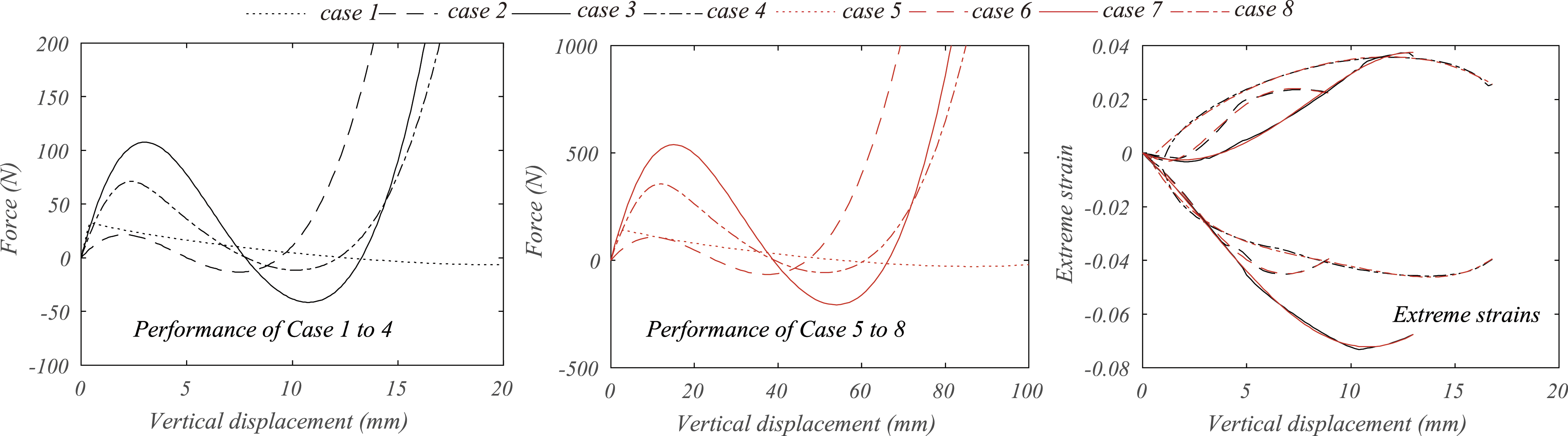
Optimized behavior of the isolator
A systematic parametric study was performed using the mechanical model to investigate the optimized parameters for bistable beams with variable sections used for QZS isolators. The study was based on a bistable beam with a horizontal length, L
x
, of 50 mm and a width, W, of 50 mm with a limiting extreme strain of 0.03 and a Young’s modulus, E, of 1000 MPa. However, as shown in the previous section, the beam can be scaled up with the investigated parameter. A different value of W and E also changes the force–displacement curves of the bistable beams proportionally as these two values change the stiffness of all sections along the beam proportionally. The figures were given corresponding to different values of R
H
and R
L
. (Figure 2) Thickness of the bistable beam, H
w
, was set to be proportional of its horizontal span, L
x
. The final results are calculated with consideration of the linear spring to comprehend the negative stiffness generated by the bistable beam which is required for the QZS isolator. The results are given in Figures 6–9 explicitly in terms of the optimized L
y
corresponding to the design limitations, loading capacity of the isolator corresponding to the optimized L
y
, and total mass of the bistable beams. The results therefore can be used to design QZS isolators. Optimized geometric parameter and performance of a bistable beam with H
w
= 0.02L
x
for a QZS isolator. Optimized geometric parameter and performance of a bistable beam with H
w
= 0.03L
x
for a QZS isolator. Optimized geometric parameter and performance of a bistable beam with H
w
= 0.04L
x
for a QZS isolator. Optimized geometric parameter and performance of a bistable beam with H
w
= 0.05L
x
for a QZS isolator.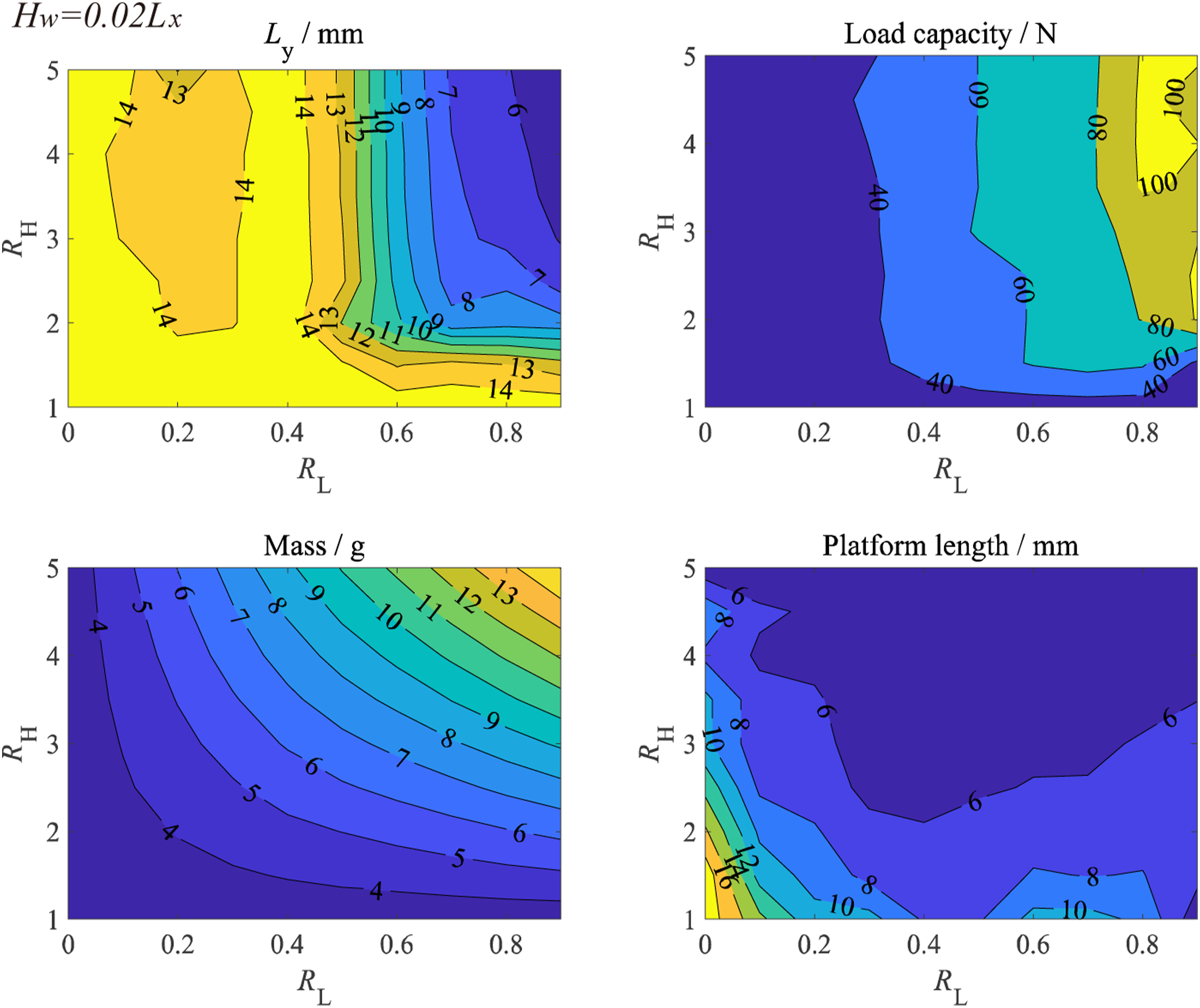
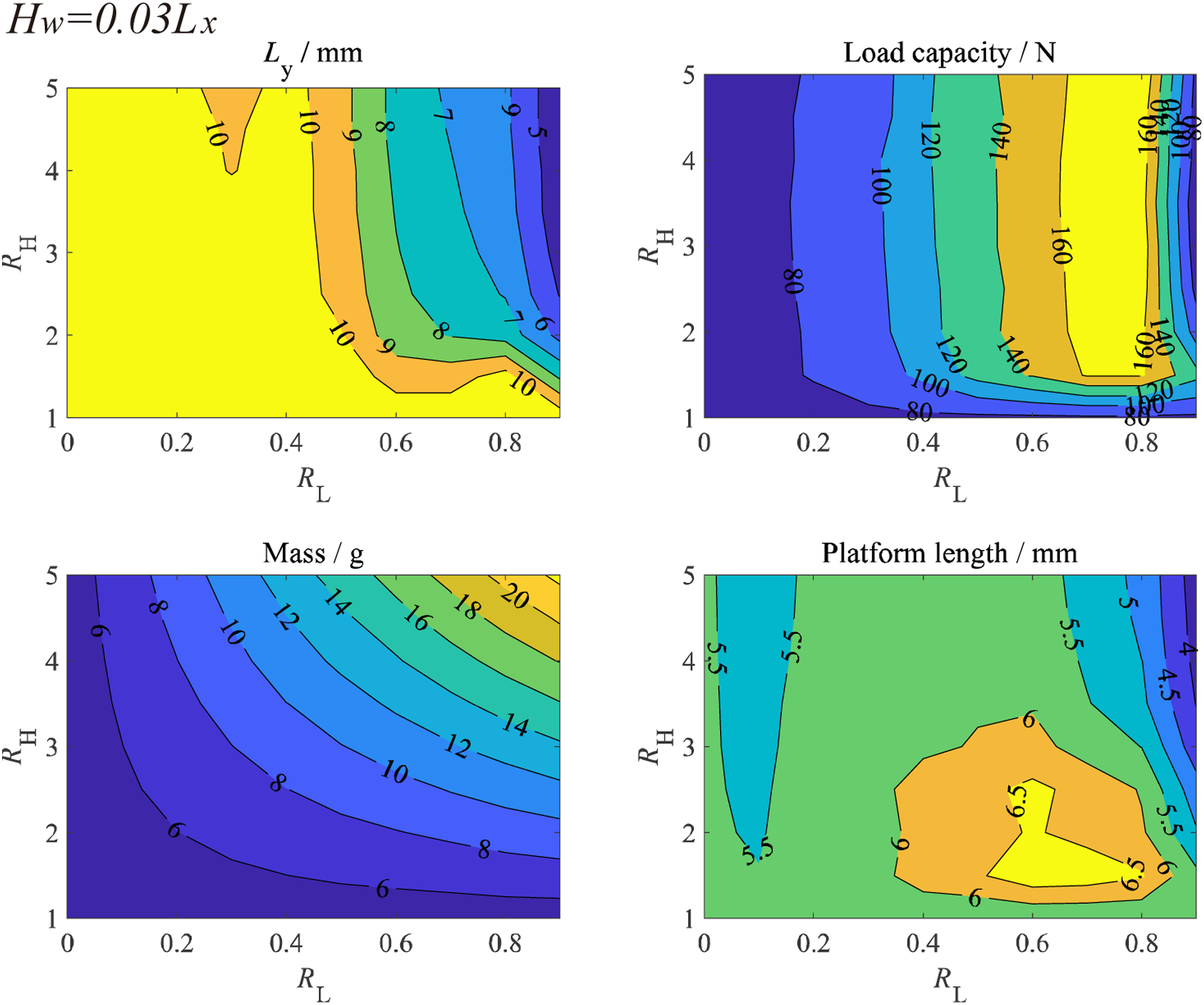
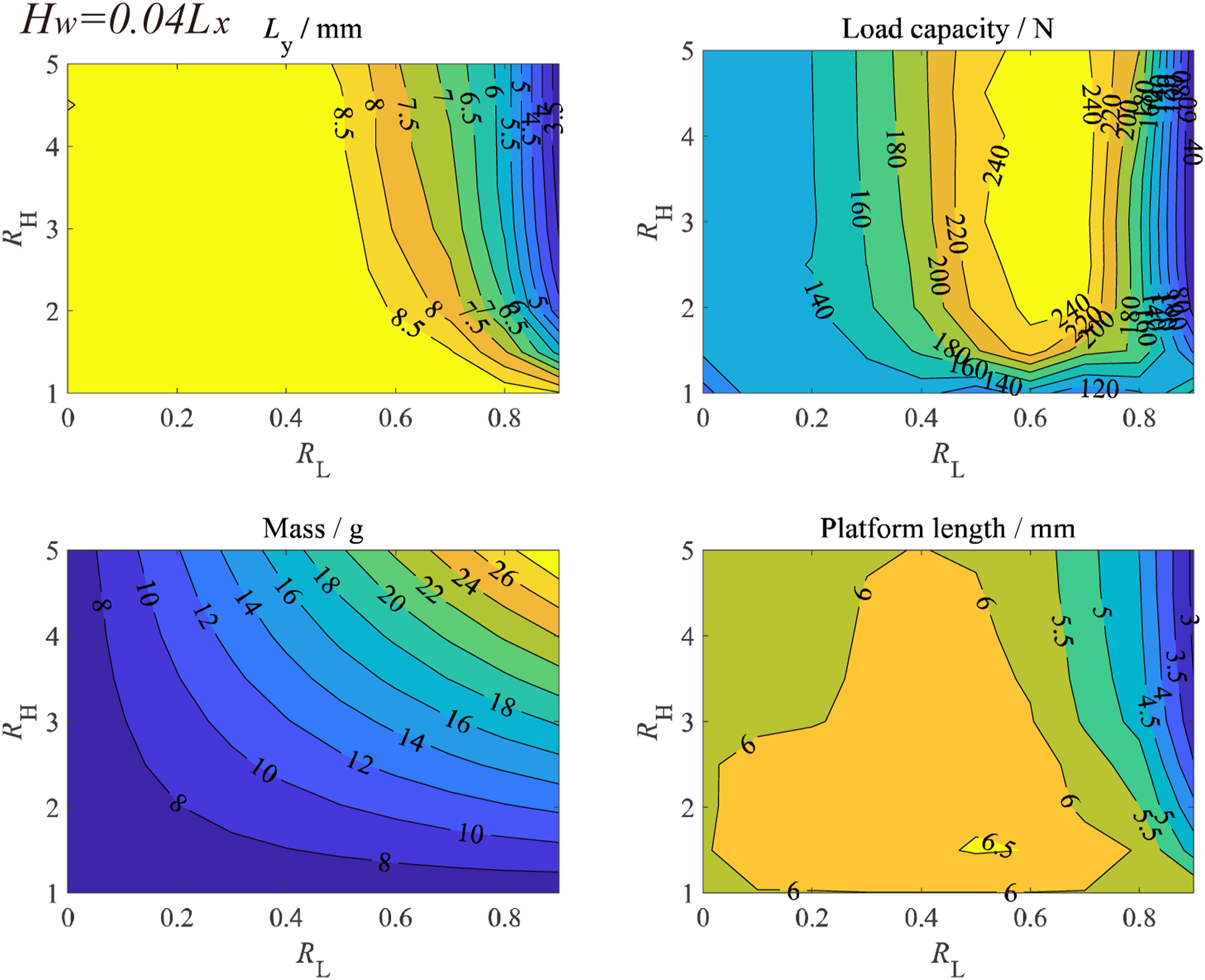
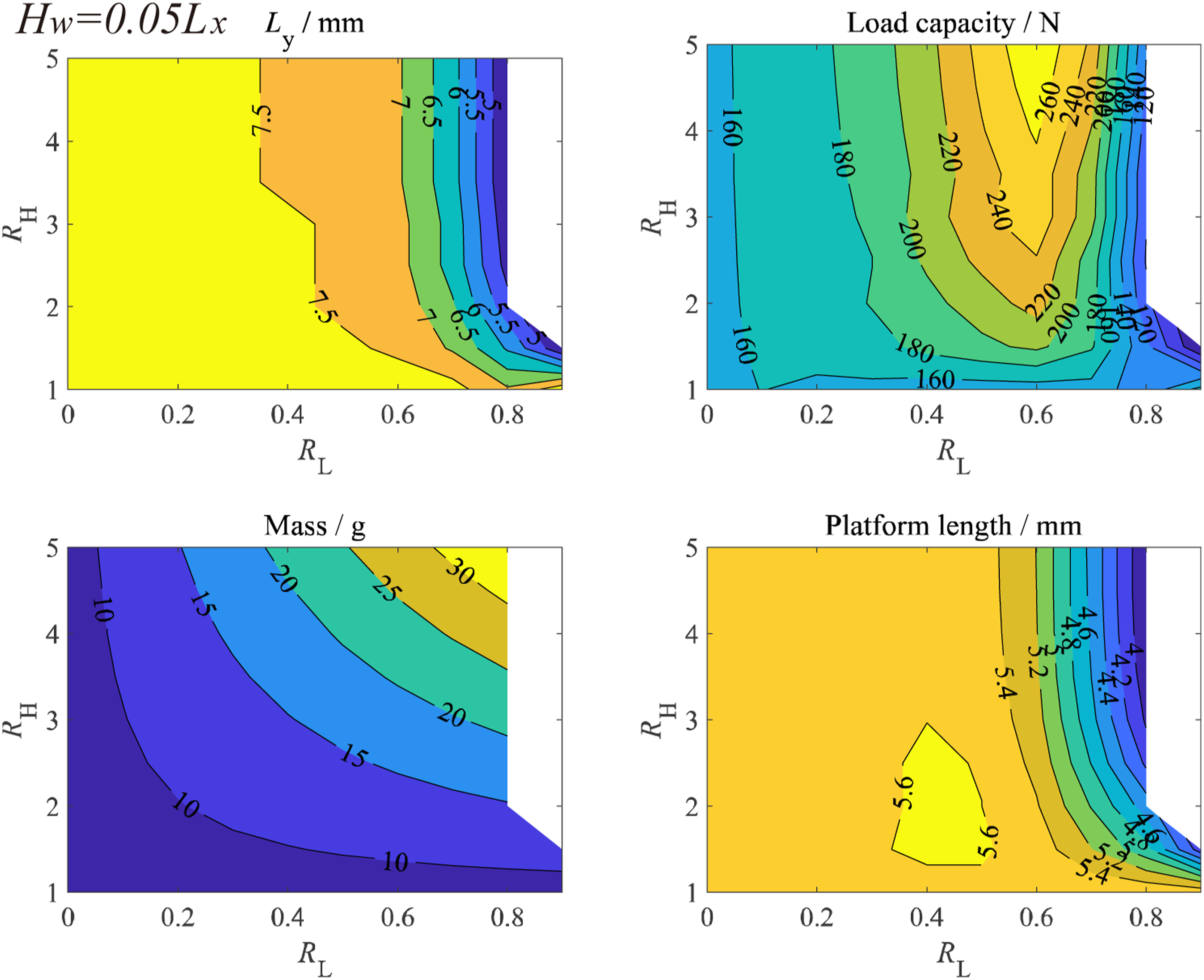
As the figures show, making sections of the bistable beams’ variable significantly increased its loading-carrying capacity. Depending on the R L , R H , and H w , the loading capacity of the beam can be increased by 130%. The optimized RH, RL, and Lx clearly depend on H w . With an increased thickness of the beam, the optimized R L to generate maximum loading capacity reduces significantly due to stricter limitation in terms of the extreme strain. On the other hand, increase of R H was found to be extremely efficient when R H is relatively low, while relatively inefficient when R H is larger than a threshold value.
In addition to the loading capacity, the range of the displacement at which the QZS system can retain the QZS is an important parameter to be considered which is related with the chaotic motion of the isolation system. The figures also show influences of the investigated parameters on lengths of the plateau region of the force–displacement curve of the bistable beam. The length was calculated as the region in which the supporting force was within 80%–120% of the weight to be isolated. The length was observed to reduce significantly with the increase of R L . On the other hand, the decrease was not monotonic, and a peak value was generally observed when the value of R L was slightly less than the value to generate the maximum loading capacity. The results indicate that the increase of the loading capacity by using a variable section in the bistable beam comes at a cost of reducing the range of displacement in which stiffness of the isolator is at an extreme low value.
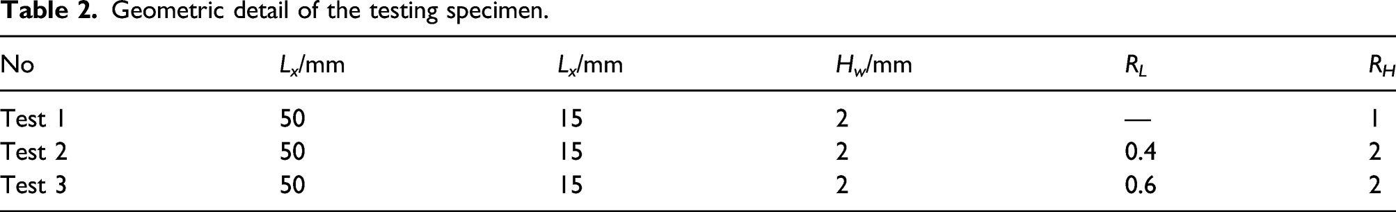
Experimental validation
Tests were performed to validate results derived from the parametric study. Three beams with uniform and variable sections were designed based on results shown in Figure 10 and composed through 3D printing using nylon material. Detailed geometry of the test specimens is summarized in Table 2. Figure 10 also shows the force–displacement curve of the specimens compared with the numerical results. As the figure shows, the model could capture behavior of the specimens well. The maximum error was generally less than 20% in terms of the peak strength. However, relatively large error was observed after repeated loading cycles. This is probably related with the loosening of the horizontal restraints with the cyclic load. Experimental validation of the bistable beam with a variable section. Geometric detail of the testing specimen.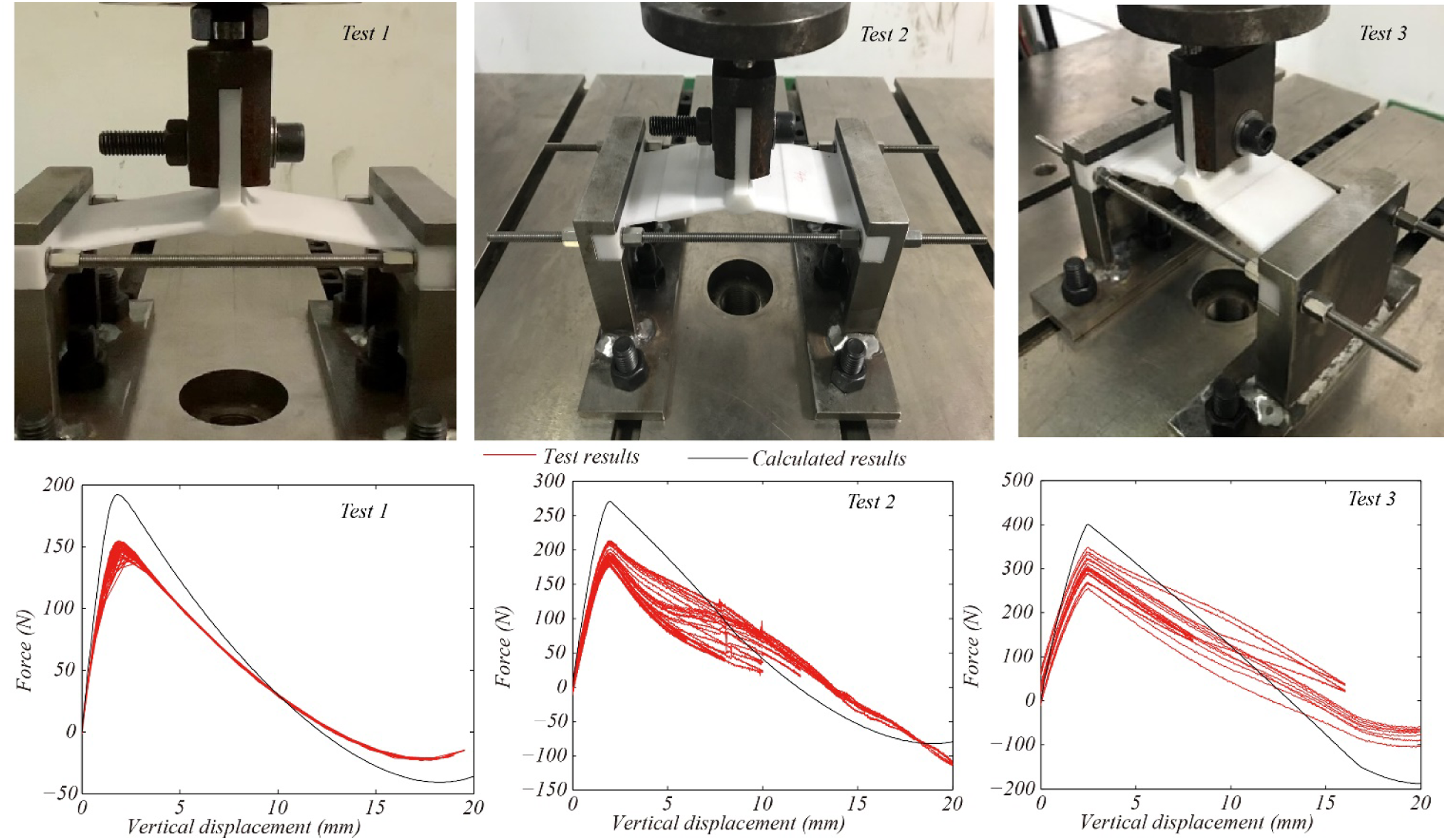
Dynamic response of the CBB isolators subjected to harmonic excitation
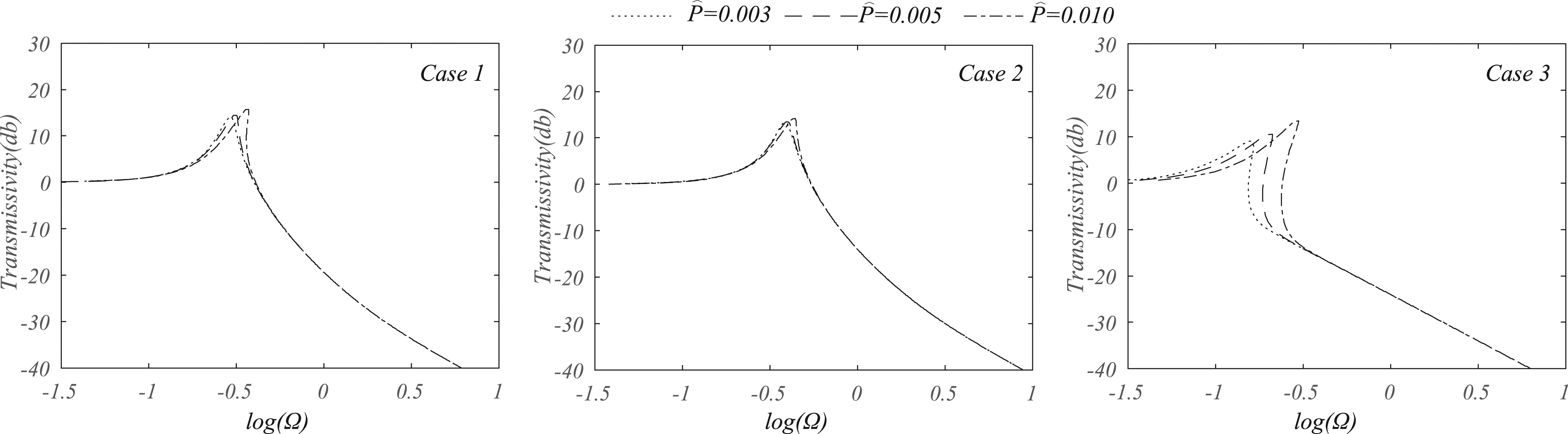
From Figures 6–9, it can be seen that using a bistable beam with a variable section can significantly increase loading capacity of the beam. However, the increase comes at a cost of narrowing the plateau of the force–displacement curve of the isolator as shown in Figure 11. Its influence on performance of the isolator is investigated with the harmonic balance method. Force–displacement curves of the isolator and its dimensionless form.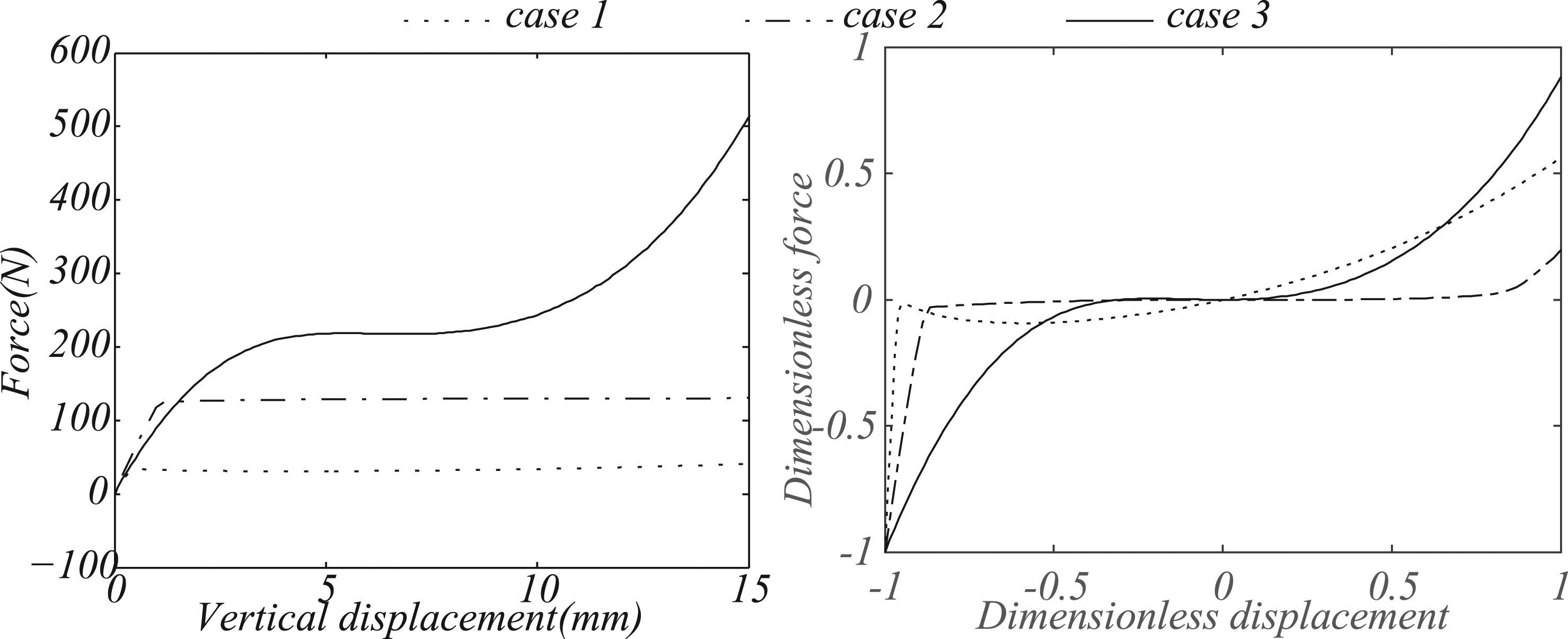
For a QZS isolator, its governing equation can be written as equation (12). Displacement transmissivity of the isolator subjected to different excitations.

Summary and conclusions
This paper aims to increase loading capacity of QZS isolators based on the bistable beam by using a variable section along length of the beam. A numerical model was derived for the beam, and parametric studies were performed based on the model to investigate optimized sectional alignment of bistable beams to increase loading capacity of the isolator which was consequently validated with tests. At last, performance of the isolator was finally investigated with the harmonic balance method. Using a bistable beam with a variable section significantly increased the loading capacity of QZS isolators. The numerical results show that with an optimized design, the weight of the isolator which can be isolated can be increased by more than 3 times with a similar extreme strain. Mechanical performance of the isolator based on the bistable beam with a variable section was validated by cyclic tests. The results show that the numerical model derived can accurately predict static behavior of the isolator. Despite increasing the loading capacity of the isolator, using the bistable beam with a variable section decreases the range of the deformation of the isolator corresponding to the very low stiffness. Its impact on performance of the QZS isolator is investigated with the method of harmonic balance.
Footnotes
Declaration of conflicting interests
The author(s) declared no potential conflicts of interest with respect to the research, authorship, and/or publication of this article.
Funding
The author(s) disclosed receipt of the following financial support for the research, authorship, and/or publication of this article: This work was financially supported by the National Key R&D Program of China (Grant No.2020YFB03502), Natural Science Foundation of Jiangsu Province (BK20190365), National Science Fund for Distinguished Young Scholars (51625803), Program of Chang Jiang Scholars of Ministry of Education. The authors wish to express their gratitude for these financial supports.