
Abstract
Several factors could affect the function of the electromagnet control system when a high-speed maglev train runs over a bridge. To enhance the robustness of the electromagnet control system to the high-speed maglev train running over the bridge, a fuzzy active control rule is introduced into the currently used proportional–integral–derivative (PID) control system. Numerical analyses are then conducted with a high-speed maglev train passing through a series of simply supported beams. The numerical results with the fuzzy PID active control are compared with the maglev train–bridge system with the equivalent linearized electromagnetic forces. The comparative results show that the introduction of the fuzzy PID control system has improved the comfort of the maglev train and that the overall dynamic response of the bridge is reduced. There is an obvious time delay for the maximum dynamic response of the bridge to the high speed of the train.
Keywords
Introduction
Maglev transport is a type of transporting mode with electromagnetic forces as the main feature. With high speed, low energy consumption, strong climbing ability, and high comfort, 1 it has great advantages during planning the transportation lines between cities with medium or long distance. During operation, the electromagnet controllers installed inside the maglev trains can actively adjust the running state of the trains by controlling the current according to the actual gap between the trains and the track. In vacuum or low vacuum environment, the ideal speed of a maglev train has a speed ability exceeding 1000 km/h, much higher than that of the existing high-speed wheel-rail trains. The dynamic studies on the traditional coupled high-speed wheel-rail train–bridge system have shown that the high-frequency excitation caused by the high-speed moving train could make the dynamic response of the bridge more intense. 2 Therefore, it is of great importance to study the dynamic characteristics of the maglev train–bridge coupling system in high-speed running state.
Actually, the maglev train–bridge dynamic system or the maglev train-guideway system is an open-loop unstable system. 3 A controller should be adopted to ensure the safety of the moving train. Therefore, the earliest version of the interaction of the maglev train and the bridge/guiderway,4–6 which used the linear lumped spring-damper or the constant force model to represent the electromagnetic force, is less rational. Wang and Nagurka 3 employed a linear quadratic optimal control strategy supplemented with integral action and preview. With this model, the nonzero steady-state gap error of the linear quadratic optimal control due to constant disturbances can be circumvented. Based on the concept of the decentralized hierarchical control, Shi et al. 7 employed a linear feedback control rule taking the maglev gap change, the acceleration, and velocity of the magnetic suspension block as the input variables. Han et al., 8 Kim et al., 9 and Wang et al. 10 adopted a five-state feedback linear control law, which added the maglev gap velocity and the position of the magnetic suspension block into the input variables compared with the controller in Shi et al. 7 Lee et al. 11 calculated and analyzed the influences of the train type, the train speed, the track irregularity, the bridge span, and the damping ratio on the dynamic performances of a low-speed maglev train–track beam system by establishing a linear quadratic Gaussian controller (LQG). An observer with Gaussian white noise assumption of the external disturbance and sensor noise was designed. Yau 12 established a neural network-proportional integral (Neuro-PI) controller to achieve the control of the maximum dynamic responses of a maglev train on an elastic track beam. In this model, the neural network method was used to determine the feedback gains of the PI controller. A linear PI controller was also used in Ju et al. 13 Wang et al. 14 employed a PD controller to describe the control behavior for a maglev train moving on a bridge. Yang and Yau 15 calculated and analyzed the dynamic responses of a maglev train–track beam-foundation coupling system by taking the maglev vehicle as a two-dimensional rigid beam, and adopting the PID controller as the electromagnet control system. The classical PID controller is used to provide a stable control of the magnetic gap under trains as a basic form of electromagnet control method in the following studies in Moazen et al. 16 and Wang et al. 17 for the maglev train–bridge system.
In the above studies about the couple vibration of the maglev vehicle–bridge dynamic system, different linear controllers were developed to model the interaction electromagnetic force between the maglev vehicle and the bridge. With them, the maglev vehicle–bridge dynamic system is close-loop stable under small disturbances. However, various factors, such as the exceeded track irregularity, the large deformation of the bridge, the deformation incompatibility at multi-span bridge joints, and the strong vibration of the bridge caused by external loads such winds and earthquakes, could affect the linear control effects and further the dynamic responses of the maglev train and the bridge. Adopting nonlinear controller is an important trend in the near future to consider the complex environment for the high-speed maglev train moving on bridges. Recently, Schmid et al. 18 integrated a nonlinear model predictive control to deal with the irregularities of the guideway. At every sampling interval, the optimal control was solved. A long enough prediction horizon was required to ensure the stability. Li et al. 19 built a nonlinear controller based on the full state feedback way. The feedback coefficients were determined through the particle swarm optimization method. Also, on-time optimization should be executed during the analysis.
The timely optimization on the controller is a good way to handle the nonlinear behavior of the dynamic system, but it actually increases the complexity and reliability of the system. This study introduces the classical PID control regulation, and the gains of the controller can be well adjusted through fuzzy rule to cover the possible instability due to the complex factors during the maglev trains running on the flexible bridge with high speed. Fuzzy PID control does not require complex optimization accompanied by the time advance. After the fuzzy PID electromagnet active control system with stable control ability is designed, a coupled high-speed maglev train–bridge analysis model is established. Meanwhile, the dynamic responses of a maglev train passing through a three-span simply supported beam under the active control of fuzzy PID is analyzed and compared with the conventional equivalent linearized spring-damped maglev system, with the aim to study the influences of the fuzzy PID active control system on the dynamics responses of the high-speed maglev train and the bridge.
Dynamic analysis method of coupled maglev train–bridge system
Electromagnetic force model
Maglev vehicles could be suspended by the electromagnetic forces provided by the electromagnetic interaction between the magnetic suspension blocks fixed on the magnetic frames and the magnetic track. Suppose that the magnetic suspension blocks are independent of each other, and that the electromagnetic control systems of the magnetic suspension blocks do not interfere with each other, the magnetic suspension blocks have no mechanical damping and elastic stiffness, and could vibrate driven by the electromagnetic force and the suspension force transformed from the vehicle body. The dynamic equilibrium equation for a magnetic suspension block can be expressed as


The electromagnetic force is a typical active control system, which could be controlled by controlling the current


Fuzzy PID control
For a basic PID control, the current

To improve the robustness of the control system as well as the control effect under the influences of various factors such as irregularity of the track, the bridge deformation, the deformation incompatibility at multi-span bridge joints, and the high speed, the fuzzy rule is introduced in the PID maglev control system. That is, to realize the real-time adjustment of PID control parameters K I , K P , and K D by fuzzy logic reasoning through the real-time monitoring of the dynamic performance of the magnetic suspension blocks (deviation of maglev gap and variation of the deviation).
Whether the fuzzy control system has good control effects lies mainly in the reasonable selection and establishment of the quantization factor, the scale factor, the membership function, and the fuzzy inference matrix. Conventional fuzzy control system usually maps the basic domain of the input quantity to the fuzzy domain through the quantization factor. The fuzzy domain of the input is divided into several intervals. Through the membership function and the fuzzy inference matrix, the fuzzy values of the output corresponding to the fuzzy values of the input are obtained. Finally, the real-time adjustment of the output could be realized by defuzzifying the output by the proportion factor. The overlapping area of the membership functions of each fuzzy domain affects the fuzzy control effect to some extent. Too large overlapping area could make the responses of the control system insensitive, while too small overlapping area could lower the robustness of the control system. Therefore, to achieve the better control effects of the designed PID control system, in the process of fuzzification of the accurate values, the track irregularity is considered. The basic domain of the deviation of the maglev gap and the variation of the deviation is calculated first by a basic PID control system considering the track irregularity. Their probability distributions are obtained. Then, the probability distributions are divided into several intervals with equal probability based on the number of the set fuzzy domains. In this way, the input variable is divided into multiple domains with equal probability. And they are then mapped into all the fuzzy domains to achieve the objective of converting the basic domain of the input variable into the fuzzy domain. Meanwhile, as the focus of the fuzzy control system, establishment of the fuzzy inference matrix is usually a fuzzy language representation based on experiences accumulated by the expert system and operators. By comparing several interference matrixes formulated, the fuzzy inference matrix established in Liu 22 is adopted.
Dynamic coupled model of maglev train–bridge system
Different from the traditional wheel-rail train–bridge coupling system, a maglev train mainly causes the vibration of the bridge with the electromagnetic force generated by the electromagnetic control system as the external excitation. In the coupling model, the maglev train and the bridge are considered as two subsystems. They interact with each other through the electromagnetic force generated by the electromagnetic control system. The dynamic coupling equations for the two subsystems are shown in the following equations (6a) and (6b)


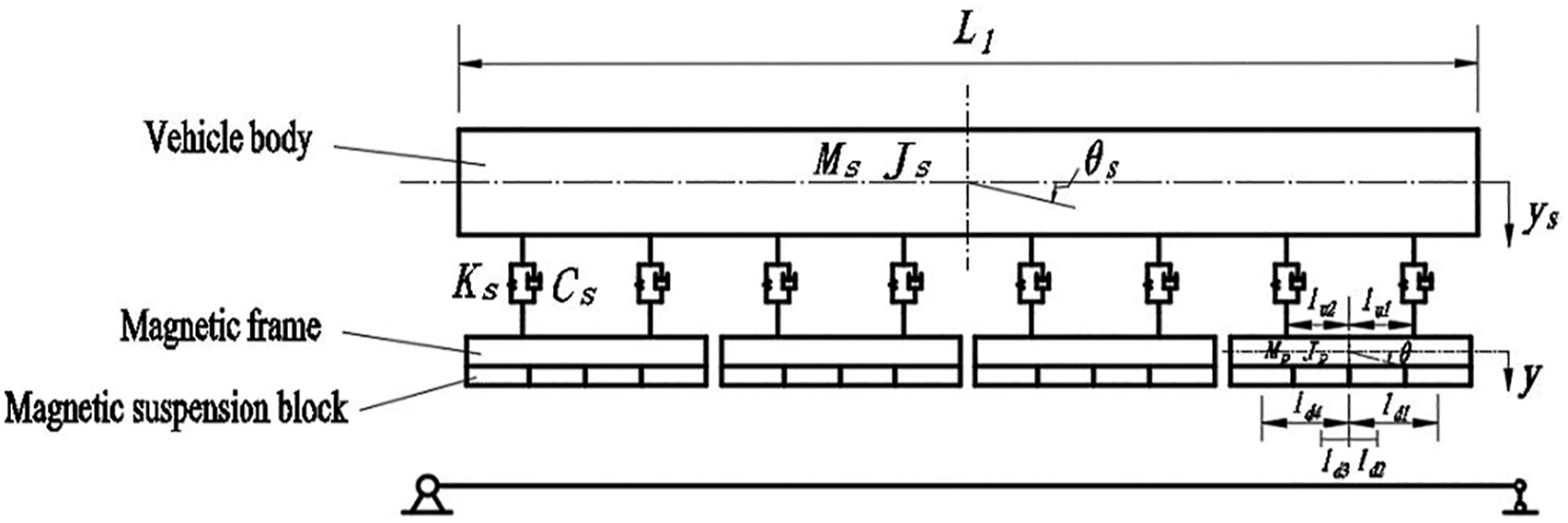
A maglev train consists of several maglev vehicles. The model of a maglev vehicle is shown as in Figure 1. It consists of the vehicle body and several maglev frames. The vertical and nodding movements of the vehicle body and the maglev frames are considered in this study to consider the vertical vibration of the high-speed maglev train–bridge system. The vehicle body and the maglev frames are connected by equally spaced linear spring-damping systems. And the magnetic suspension blocks are regarded as distributed on the respective magnetic frames with equal space. Dynamic equilibrium equation of the vehicle body is not affected by the maglev control system, can be referred to the Wang et al.
23
According to the D’Alembert’s principle of dynamics, the dynamic equilibrium equations for a single maglev frame at the static equilibrium position are established as follows: Vertical movement of maglev frame 2. Nodding movement of maglev frame Simplified model of maglev vehicle.


Solution of system
From the dynamic equation of the magnetic suspension block (equation (1)), the maglev gap is determined jointly by the electromagnetic force and the secondary suspension force (provided by the spring-damping systems between the vehicle body and the maglev frame). Meanwhile, the maglev gap determines the magnitude of the electromagnetic force in return. In the initial state, the influences of the secondary suspension force on the performance of the electromagnetic force control system cannot be considered since the dynamic responses of the vehicle cannot be accurately determined. Therefore, in the initial state, it is assumed that the electromagnetic force on the magnetic suspension block relates only to the maglev gap formed by the irregularity of the magnetic rail, that is, the term
The dynamic responses of the maglev vehicle subsystem in equation (6a) are obtained by solving the vehicle motion state-space equation. Let

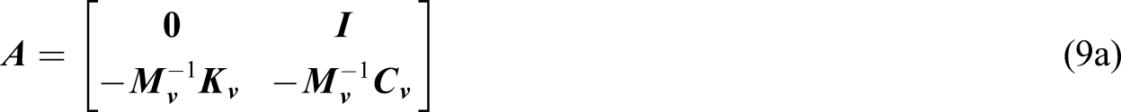
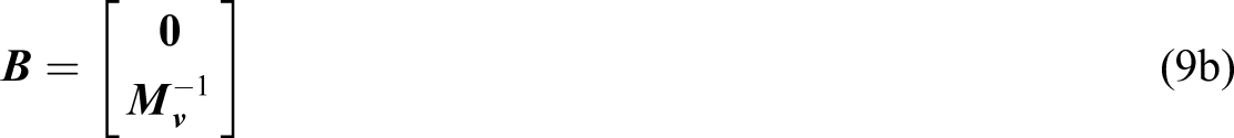
Put the maglev vehicle dynamic equilibrium equation further into matrix, and the coefficient matrix A20*20 and the input matrix B20*16 could be obtained as follows

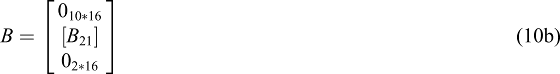
The sub-matrixes are shown in the following equations (11), (13), and (15)
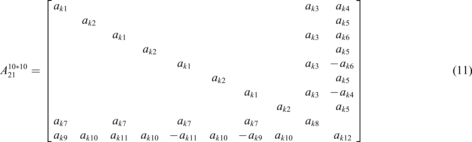
The corresponding matrix elements are


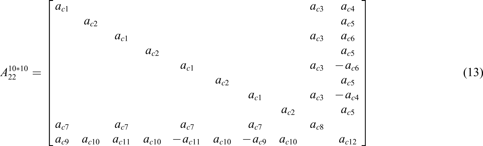
The corresponding matrix elements are


The corresponding matrix elements are
To analyze the influences of the secondary suspension on the maglev control force and the influences of the electromagnetic force on the dynamic response of the bridge, the electromagnetic force acting between the magnetic suspension block and the bridge u = {Fi}16*1 and the dynamic response of the magnetic vehicle body {X
v
}1*10 are simultaneously output in the output term of the state-space equation. Let the output vector

It could be deduced the output matrix C26*20 and the transmit matrix D26*16 as follows


Under the premise of the stable control of a single magnetic suspension block, the electromagnetic forces of different magnetic suspension blocks under different time steps are obtained by cyclic calculation, which are then substituted into the state-space equation (equations (8) and (17)) to calculate and extract the dynamic response of the vehicle. Meanwhile, the electromagnetic force of different magnetic suspension block at different time step is applied in the bridge model established by ANSYS in the form of concentrated force to calculate the dynamic response of the bridge. 24 Repeat the calculation until the difference in the electromagnetic force between two calculation results does not exceed the limit value, then it could be considered that the results converged.
Dynamic response analysis of high-speed maglev train–bridge system
Analysis parameters
Parameters of maglev vehicle and simply supported beam.
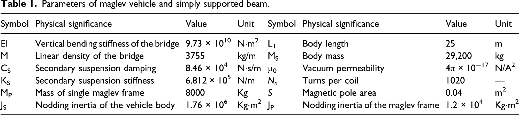
Considering the influences of the track irregularity on the high-speed maglev train–bridge dynamic system, the orbital irregularity spectrum of the maglev line discussed in Tsunashima and Abe
26
is adopted as the target spectrum, and the typical trigonometric series method (equation (19)) is used to obtain the irregularity sample of the magnetic track
Effects of fuzzy PID control
To study the influences of the introduced fuzzy PID control system on the dynamic effects of high-speed maglev train–bridge coupling system, operation of single maglev vehicle on a multi-span simply supported beam is analyzed as the object. By referring to Wang et al., 23 the electromagnetic force between the maglev vehicle and the track is simultaneously simplified to a series of equally spaced linear spring-damping models for comparison background. In this equivalent linear simplified model, the equivalent magnetic gap spring stiffness is 1.18 × 10⁸ N/m and the equivalent magnetic gap damping is 2.15 × 10⁶ N·s/m. Wang et al. 23 compared the influences of different spans of the simply supported beam, among which the three-span simply supported beam is most representative. Three-span simply supported beam is also selected for this analysis with fuzzy PID control system. The middle span of the third span (the last span) is taken as the representative to analyze dynamic response of the bridge.
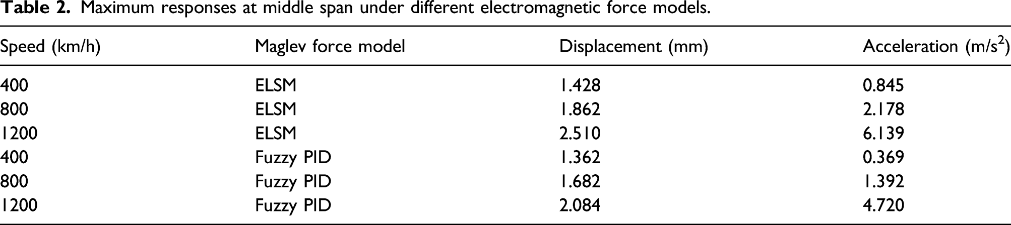
Figures 2 and 3 show the vertical deformation and acceleration time history in the middle of the third span in different electromagnetic force models (the fuzzy PID control model and the equivalent linear simplified model, ELSM for short) when the maglev vehicle runs at 400 km/h, 800 km/h, and 1200 m/h. In these figures, the horizontal coordinate indicates the mileage of the head of the maglev train. 50∼75 m is the process of the maglev train going on the third span, while 75∼100 m is the process of the train exiting this span. The lines represent the dynamic responses under fuzzy PID control, while the dotted lines represent the dynamic responses under ELSM (it is same in Figures 4–6). From the results, as the speed of the maglev train increases, the deflection and acceleration of the simply supported beam increase generally. With the increase of the speed, the maximum dynamic responses under both electromagnetic force models showed time delay phenomenon. When running at 400 km/h, the vertical deflection of the mid-span reaches the maximum as the vehicle travels to 75 m. At this moment, the maglev train is completely on the third span simply supported beam. But for 1200 km/h, the vertical deflection of the mid-span reaches the maximum when the vehicle drives to 80.33 m. At this moment, the maglev train is exiting the bridge. The reason for the time delay phenomenon is that the speed of the bridge vibration developing to the maximum is lower than the heading speed of the maglev train, making the vibration could not develop fully when the maglev train passes at a high speed. When the speed of the maglev is 400 km/h, the dynamic responses of the simply supported beam under fuzzy PID control differs little from the equivalent linear model. With the increase of the maglev train speed, the difference of the dynamic responses of the simply supported beam becomes larger between the two electromagnetic force models. For the third span, when the vehicle speed reaches 800 km/h, the mid-span deflection (1.68 mm) of the simply supported beam under fuzzy PID control increases about 21% compared with that under ELSM (1.39 mm). Figures 4 and 5 show the vertical deformation and acceleration time history in the middle of the second span in different electromagnetic force models when the maglev train runs with the speeds of 400 km/h, 800 km/h, and 1200 m/h. In these figures, the horizontal coordinate also indicates the mileage of the head of the maglev train. 25∼50 m is the process of the maglev train going on the second span, while 50∼75 m is the process of the train leave this span. For the second span simply supported beam, when the speed reaches 800 km/h, the mid-span deflection (1.67 mm) under fuzzy PID control lowers about 10% compared with that under ELSM (1.86 mm). Vertical displacement in the middle of the third span under different electromagnetic force models. Vertical acceleration in the middle of the third span under different electromagnetic force models. Vertical displacement in the middle of the second span under different electromagnetic force models. Vertical acceleration in the middle of the second span under different electromagnetic force models. Vertical acceleration of vehicle body under different electromagnetic force models.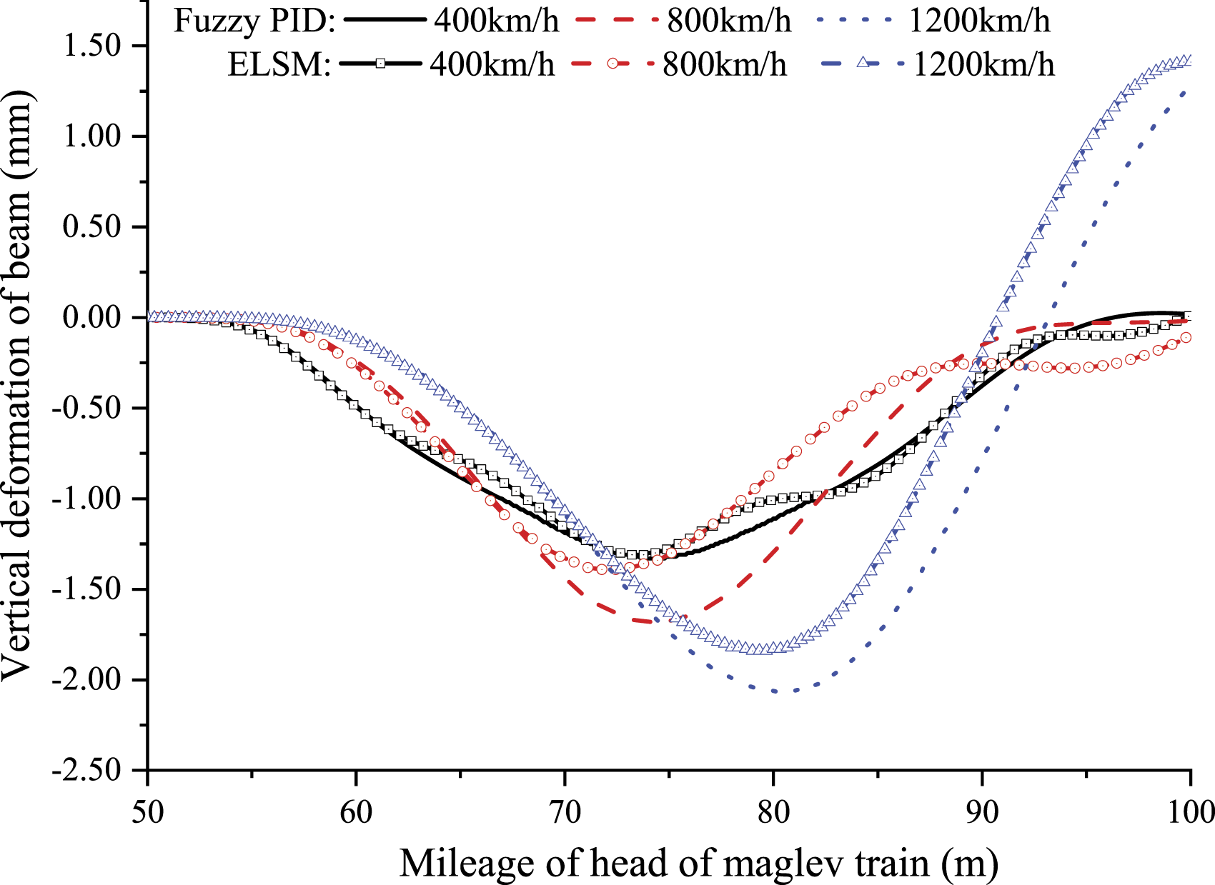
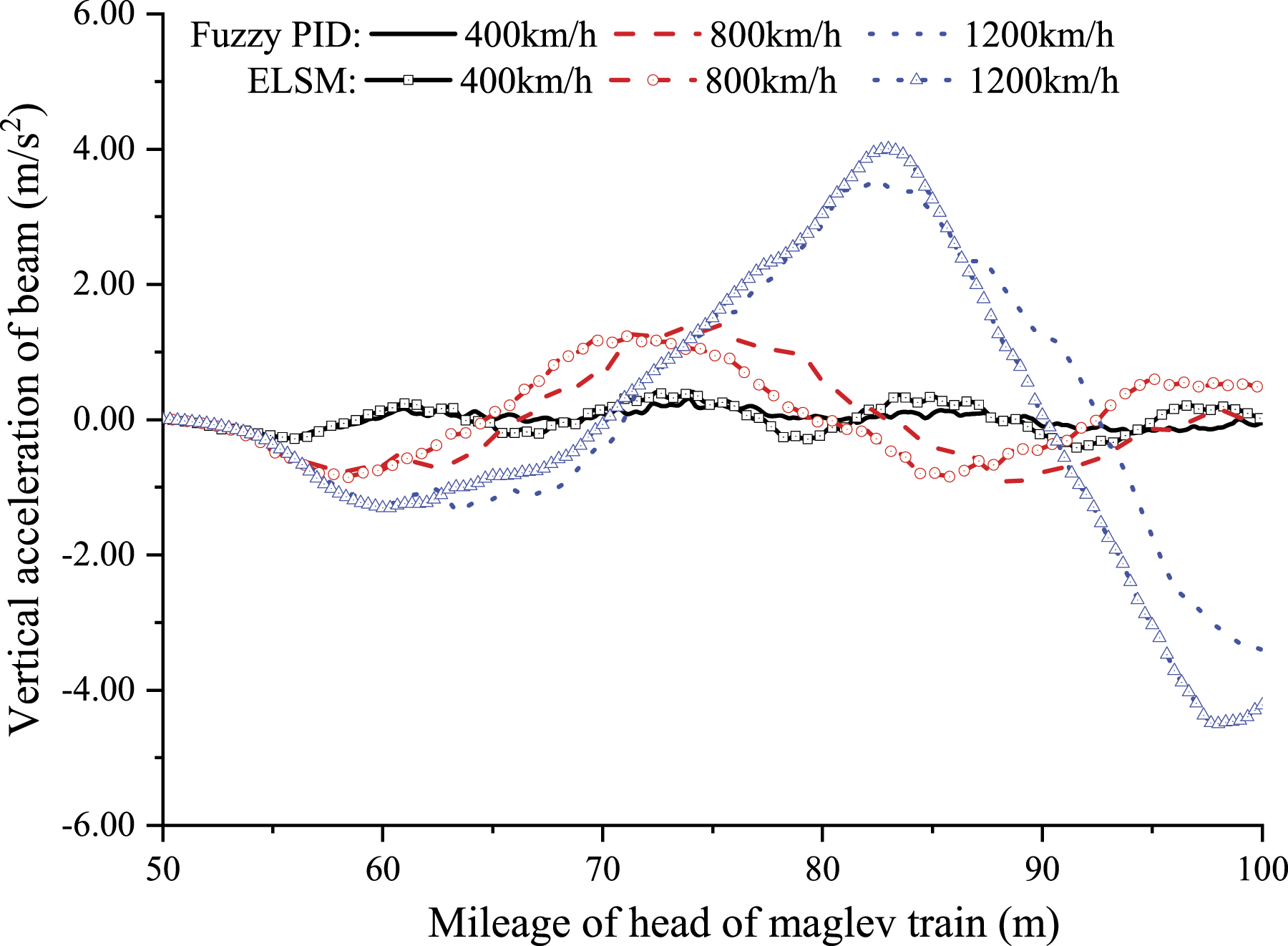
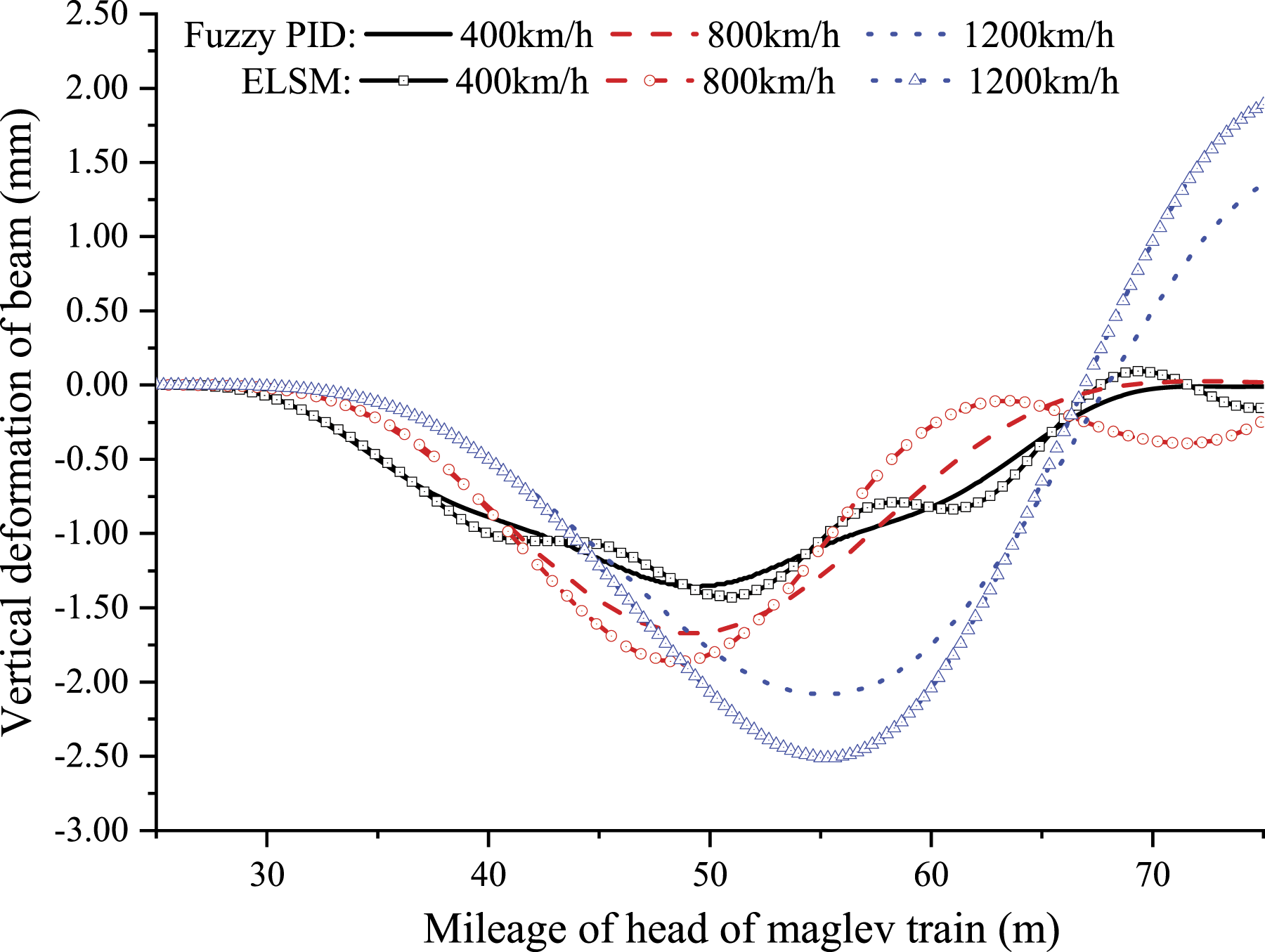
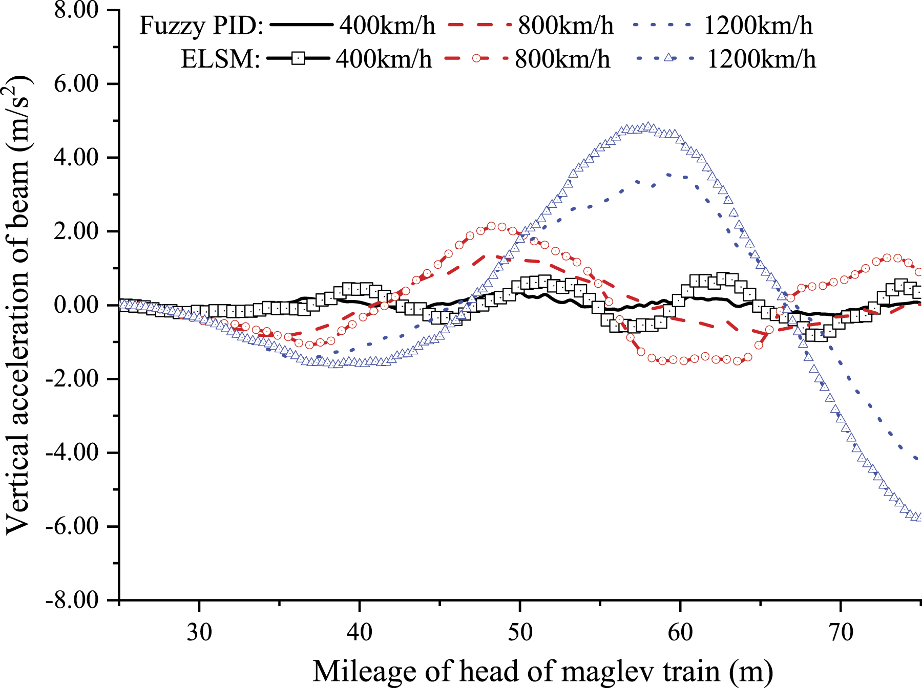
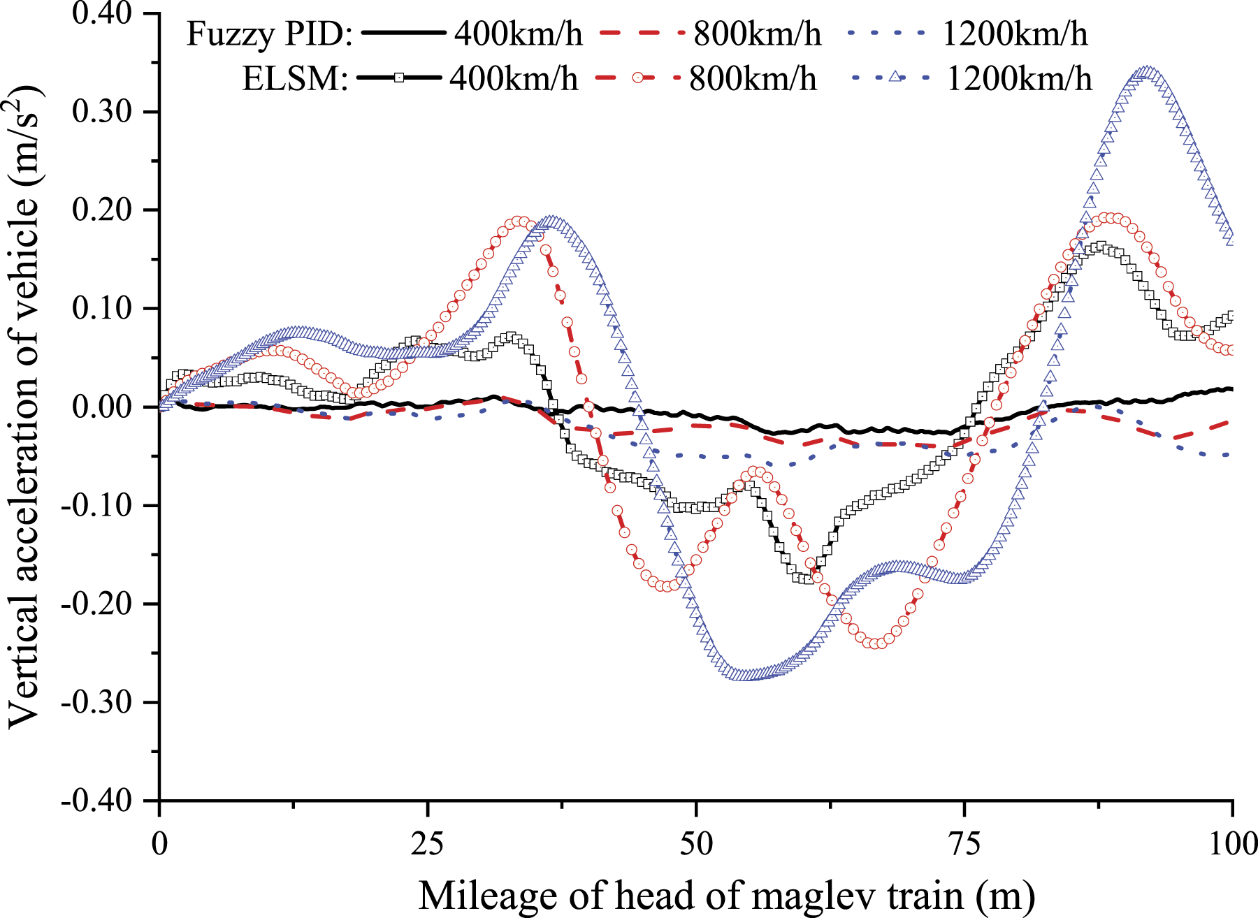
Figure 6 shows the vertical acceleration time history of the vehicle body under different electromagnetic force models when the maglev vehicle runs with the speeds of 400 km/h, 800 km/h, and 1200 m/h. As the speed increases, the dynamic response of the vehicle body also shows an increasing trend. At different speeds, the introduction of fuzzy PID control system has improved the running performance of the train. Under the ELSM, the maximum acceleration of the vehicle body increases obviously with the increase of the speed, while the increase of the speed under the fuzzy PID control has limited effects on the maximum vertical acceleration of the vehicle body.
Maximum responses at middle span under different electromagnetic force models.
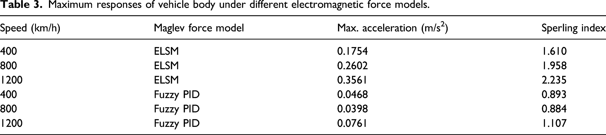
The time history of the vertical acceleration of the vehicle body under fuzzy PID control is shown in Figure 7. From which, it can be clearly observed that as the speed increases, the vibration of the vehicle body is intensified. In addition, although the speed is different, when the running mileage of the maglev train reaches about 60 m, the vehicle body vibrates most severely. At this moment, the maglev train runs into the third span bridge. By comparing the irregularity sample of the magnetic track, such result is caused by irregular magnetic track. From the dynamic results of the vehicle body in Table 3, it can be found that as the speed increases, the dynamic responses of the vehicle body are intensified generally. However, the presence of the maglev control system makes the dynamic responses of the vehicle body small all the time, far below ELSM. According to the critical standard of vehicle comfort index in Design Code for High-speed Railway
27
in China, the fuzzy PID maglev control system adopted in this analysis has better control performance, and the maglev vehicle comfort index (Sperling index in Table 3) is superior. Comparing Figures 6 and 7, the vertical acceleration time history of the vehicle body under ELSM is smoother than that of the vehicle body under the fuzzy PID control system. Because the gains in fuzzy PID are adjusted under each time step, the electromagnetic force does not change continuously, thus making the vertical acceleration time history curve of the vehicle body exhibit fluctuation to a certain degree. Vertical acceleration of vehicle body under fuzzy proportional–integral–derivative control. Maximum responses of vehicle body under different electromagnetic force models.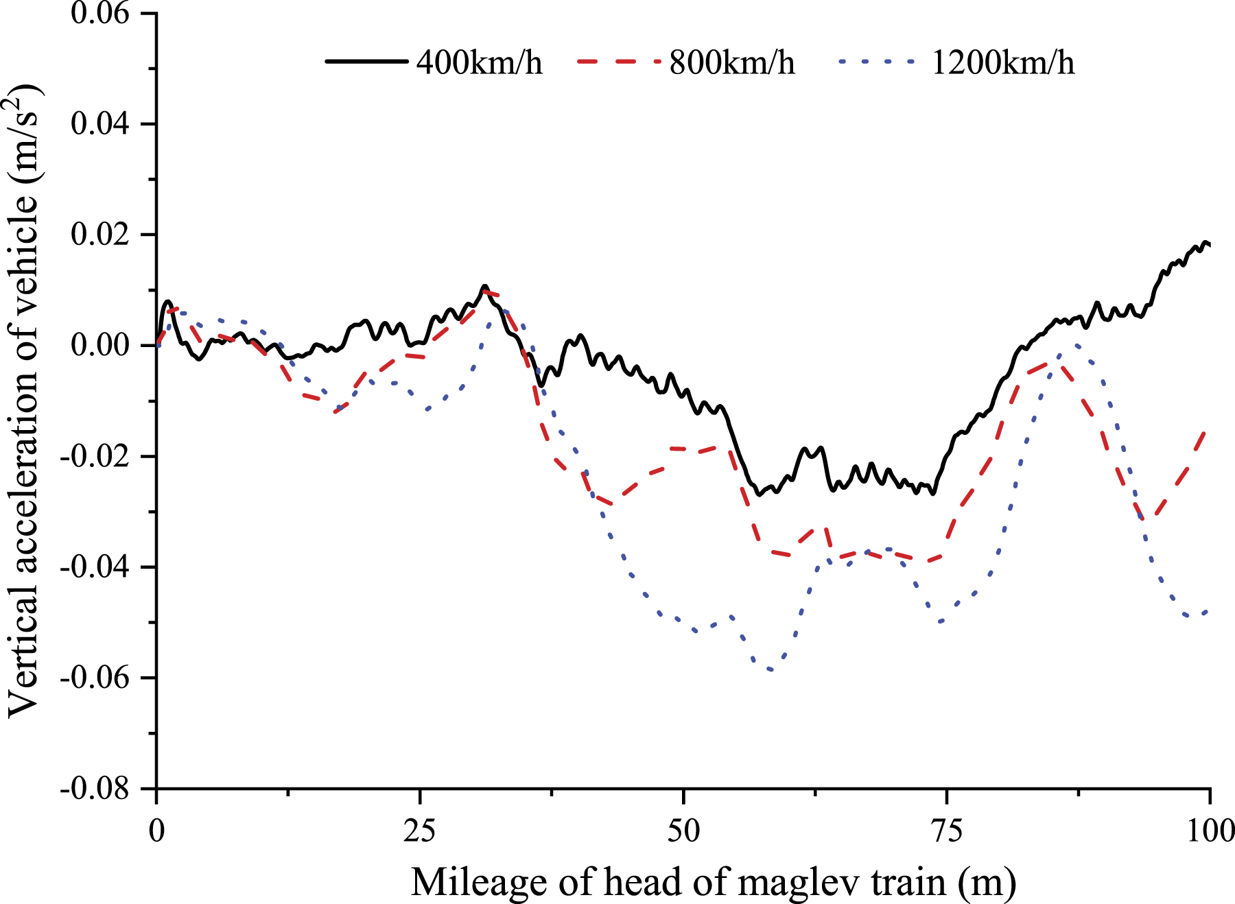
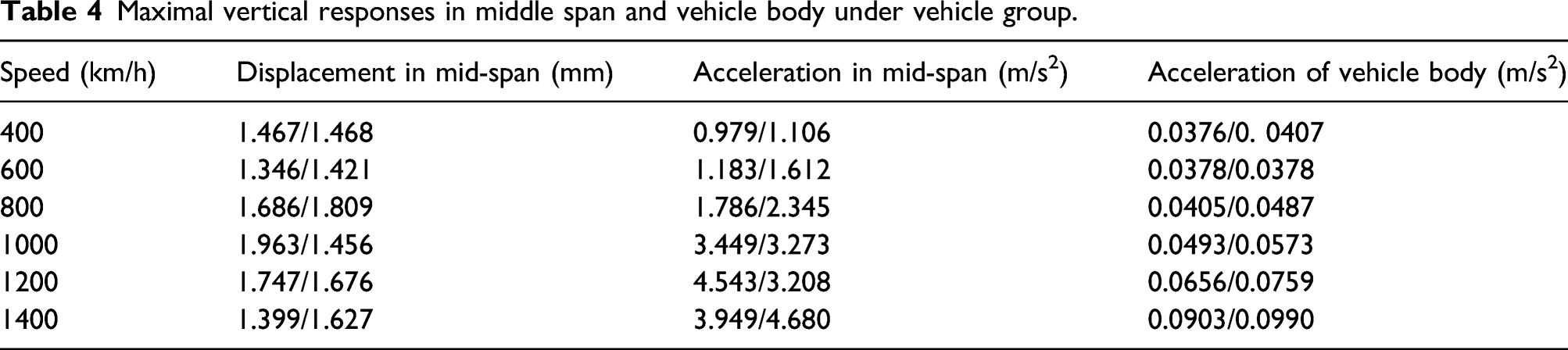
Influences of multiple vehicle grouping
Maximal vertical responses in middle span and vehicle body under vehicle group.
Conclusion
For the maglev trains moving on the bridge with high speed, many factors may lead to exceeded disturbance to the train. Nonlinear electromagnetic controller is a necessary trend in the coupled dynamic analysis for the high-speed maglev train–bridge system. Based on the classical PID control regulation, the conventional fuzzy PID is introduced to establish the coupled dynamic system of the high-speed maglev train–bridge. The gains can be adjusted through fuzzy rule according to the timely disturbance. The nonlinear electromagnetic controller can thus be reflected. Under the premise of the designed electromagnetic control system, the dynamic responses of the maglev train passing through a series of simply supported beam at different high speeds and in different vehicle groups are studies and compared with that of the equivalent linear spring-damping control system. Main conclusions are listed as follows: The introduction of fuzzy PID control system has improved greatly the ride comfort of the maglev train moving on the bridge with high speed. Generally, the Sperling index is superior due to the adequate electromagnetic control. The reduction of the dynamic response of the vehicle body lowers the fluctuation of the electromagnetic force acting on the bridge in turn, resulting in the decrease of the dynamic responses of the bridge to some degree. Since the gains in fuzzy PID are adjusted at each time step, the electromagnetic force does not change continuously, thus making the acceleration time history of the vehicle body fluctuate with a certain degree. For a single maglev vehicle, the dynamic responses of the vehicle body and the bridge increases gradually with the increase of the train speed. The maximum dynamic response has obvious time delay with the increase of the speed of the train. The reason for the time delay phenomenon is that the vibration could not develop fully when the high-speed maglev train passes on. With the increase of the number of vehicles grouped in a train, the dynamic response of the vehicle body increases also gradually. The maximum responses of the bridge increase generally with the increase of the maglev train speed. For some special train speed (around 1000 and 1200 km/h here), vibration elimination phenomenon occurs, leading the maximum responses of the bridge under four vehicles group even lower than that under two vehicles group.
Footnotes
Declaration of conflicting interests
The author(s) declared no potential conflicts of interest with respect to the research, authorship and/or publication of this article.
Funding
The author(s) disclosed receipt of the following financial support for the research, authorship, and/or publication of this article: This work was supported by National Natural Science Foundation of China [51878579, 51525840] and Major Science and Technology Project of China Railway Construction Co., Ltd. [2018-A01].