
Abstract
Lean combustion technique and annular geometries are preferred in aero-engines and gas turbines, which however may lead to azimuthal combustion instabilities. Active control can be used to stabilize combustion instabilities. Due to its easy use, linear feedback controllers embedded with linear flame response models under weak perturbation amplitude are typically preferred. However, flame responses to oncoming disturbances are typically nonlinear; such controllers are not guaranteed to stabilize. Model-based control strategies generally focus on axisymmetric cases, even though symmetry breaking of azimuthal thermoacoustic modes often occurs in annular combustors. This work uses an improved thermoacoustic model to simulate combustion instabilities within annular combustors, providing a platform on which control strategies development can be performed. The improved model takes into account the nonlinear flame response and the symmetry breaking of azimuthal modes. Single-input single-output control strategies targeting on these nonlinear instabilities are developed in this work. Such controllers can achieve stability for linear and nonlinear fluctuations as well as in symmetric and non-axisymmetric cases. The controllers adopt the
Introduction
In order to reduce
In order to achieve uniform temperature distribution at the turbine inlet and combustion chamber geometry compactness, modern gas turbine combustion chambers usually have an annular geometry with multiple azimuthally arranged burners. 9 The largest size of the annular combustor is often the circumference, and the lowest acoustic resonance frequency is then associated with modes in the azimuthal direction. Annular combustors often suffer from azimuthal thermoacoustic instability, 10 and its model-based control is then more challenging than that for longitudinal modes because of the high complexity of its physical process and the modeling of annular combustors.
The design of traditional linear feedback controllers for annular combustion chambers is typically based on the OLTF corresponding to small and linear perturbations. 11 However, such feedback controllers are always activated from within nonlinear limit cycle oscillations since the dynamics of real unstable combustors become dominated by nonlinear mechanisms once perturbation amplitudes grow sufficiently, during which the linear OLTF will be invalid. So the effectiveness of these controllers is not guaranteed. 7 There has been no systematic research work to solve this problem until now.
When the flame response inside multiple burners is different, the rotating symmetry of azimuthal mode will be broken, 12 and such mode is defined as the non-axisymmetric case in this study. The case that the flame responses inside multiple burners are identical is considered axisymmetric. The design of the controller is a big challenge when the azimuthal mode of the annular combustor exhibits axial asymmetry. A multiple-input-multiple-output feedback controller has been designed for modal annular combustors with different burner types. 11 In practice, it would be highly desirable to reduce the number of feedback loops and sensors/actuators as far as possible. When considering nonlinear flame responses, the form of symmetry breaking becomes more complicated. It is thus much more attractive to develop a single-input single-output (SISO) controller to effectively suppress the unstable mode exhibiting asymmetry in annular combustors.
This work improves the annular combustor model developed by Bauerheim et al. 13 The modified model takes into account the effects of flame nonlinearity, bulk fluid flow, and viscothermal damping inside the burners which are ignored in the original model for the sake of simplicity. The model combustor utilizes a pressure transducer as the controller sensor, and a valve on the fuel feed line which can modulate the fuel flow rate of all burners simultaneously and equally is used as the actuator.
In this work,
The rest of this paper is arranged as follows. The next section describes the annular combustor model used in this work, including the principle of the network reduction methodology and nonlinear flame transfer function (NFTF). Analysis of the azimuthal thermoacoustic modes is carried for both the axisymmetric and the non-axisymmetric cases in the “Analysis of the unstable azimuthal thermoacoustic mode” section. The “Feedback control of azimuthal combustion instabilities” section presents the design processes of
Combustor model
Description of the network model
A thermoacoustic network model for PBC (plenum+burners+chamber) configuration 13 is used to develop model-based feedback controller strategies. This work improves the previous model by taking into account the flame nonlinear response, bulk fluid flow, and thermal viscosity inside the burners.
The model of the annular combustor is shown schematically in Figure 1(a). The two ends of the burners are, respectively, connected to the annular plenum and chamber. Closed-end boundary conditions are used here at the inlet of the plenum and the outlet of the chamber. The half-perimeter and cross-sectional area of the cavities are represented by
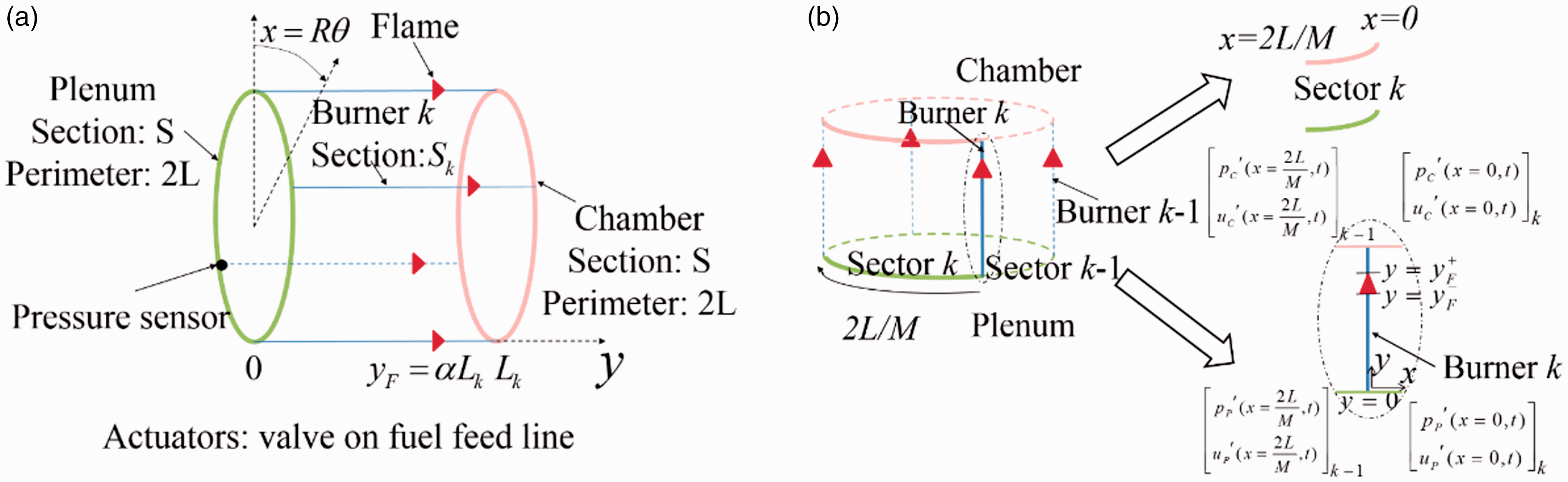
Schematic diagram of (a) the PBC configuration and (b) annular network reduction. Source: taken from Bauerheim et al. 13
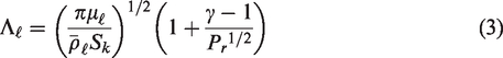
The model developed in Bauerheim et al. 13 did not account for the bulk fluid flow and any damping mechanisms. According to mass conservation equation and equation (3), these assumptions are acceptable for annular cavities since their sections are relatively large. However, the cross-section area of the burners can be very small in some real combustors, thus the thermal viscosity and bulk fluid flow inside the burners should be considered.
Following the approach given in Bauerheim et al.,
13
the full configuration is split into M sectors (Figure 1(b)). Then, for each individual sector, the acoustic problem is separated into three parts:
Propagation in the annular cavities (plenum and chamber) can be described by a 4 × 4 rotation matrix Propagation in the kth burner without passing through the flame:
The cross-section area of the burners is much smaller than that of the annular cavities (including the plenum and the chamber). It should be noted that the viscothermal damping effect should be accounted for if the burner channel radius is smaller than 5 cm for room temperature.
5
Therefore, the bulk fluid flow and viscothermal damping effects inside the burners are taken into consideration. The pressure perturbation


The acoustic propagation relation in the upstream and downstream regions of the flame inside the kth burner can be described by a 2 × 2 matrix 3. Coupling between the plenum and the chamber via the burners:
As shown in Figure 1(b), an H-shaped junction is used to link the acoustic states of the input (corresponding to the end of the sector k−1) and the output (located at the beginning of the sector k). This relation can be expressed as

The 1D Euler equations (continuity, momentum, and energy equation) in the kth burner have the form
1


The subscripts
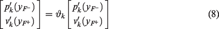
The detailed derivation process of the jump condition and the exact form of
The transfer matrix of the kth sector is
The NFTF
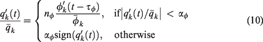
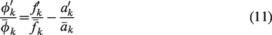
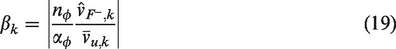
In this work, the flame nonlinear response is considered through a gain/time delay flame model with saturation bounds. The mean heat release per unit area for the burner k is denoted by
The definition of
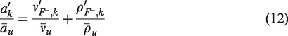
The mass flow of air immediately before the flame location inside the kth burner can be linearized to obtain
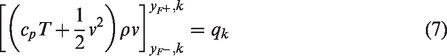
The mean heat release rate per unit area of the kth flame is given by
24
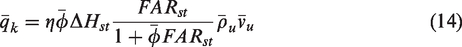
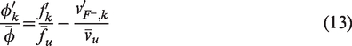
In equation (14),

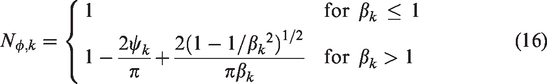
In equation (16),
To avoid unrealistic unstable modes at high frequencies, the NFTF, equation (15), may be filtered by a first-order low-pass filter23,25

Analysis of the unstable azimuthal thermoacoustic mode
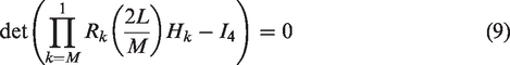
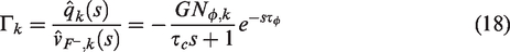
By inserting equation (18) into equation (9), a dispersion relation of azimuthal thermoacoustic modes is obtained. Note that
Axisymmetric case of the unstable azimuthal thermoacoustic mode
One assumes that flames’ parameters and responses in each burner are the same. If the oscillation develops gradually from a weak disturbance, the fractional velocity perturbation at the location immediately upstream the flame inside each burner
One then solves equation (9) and gets the value of
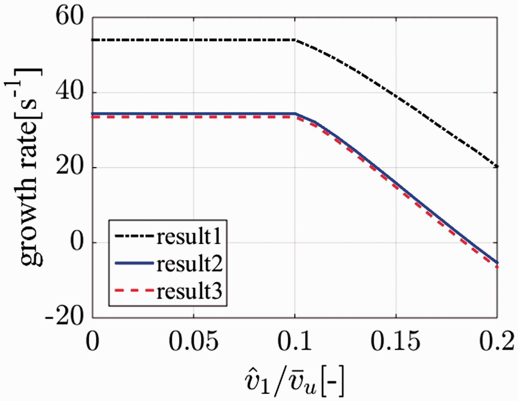
Evolutions of the growth rate of the first mode with
It is found that only the first mode is unstable, as shown in Figure 3.
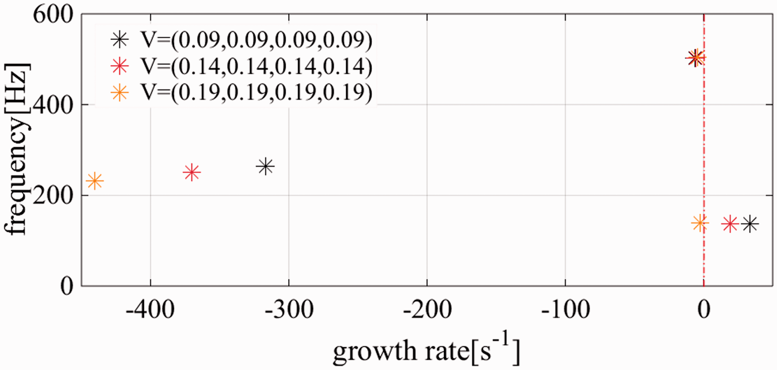
Frequencies and growth rates of the first three modes for three axisymmetric cases.
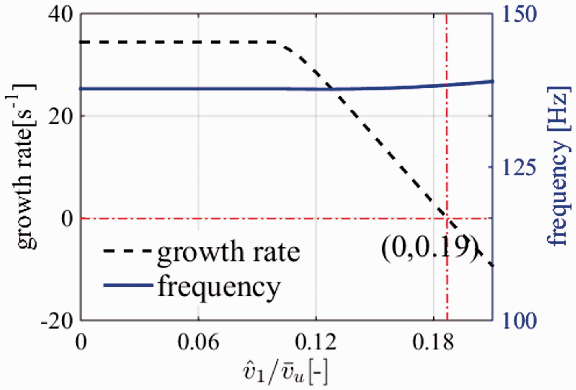
Evolutions of the eigenfrequency and corresponding growth rate of the first mode with
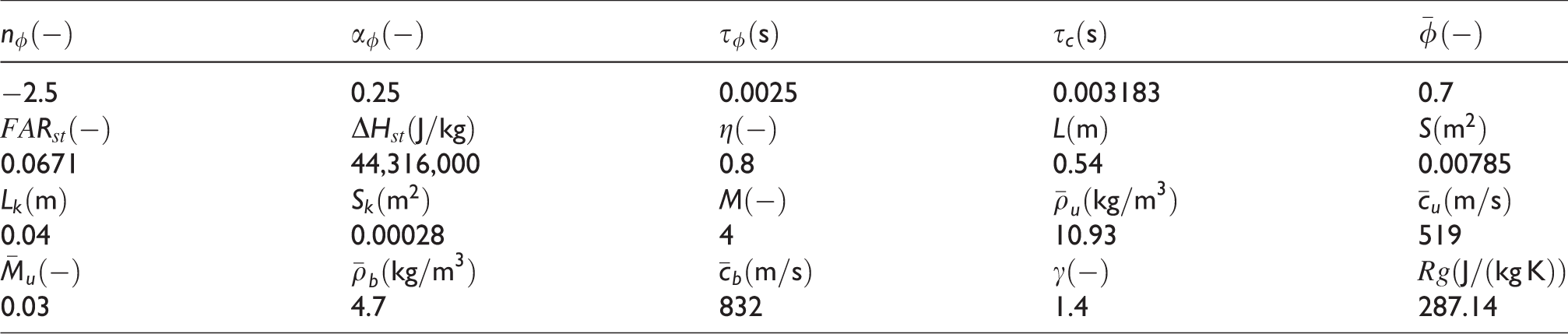
Parameters used in the frequency domain analysis for both the axisymmetric and the non-axisymmetric cases.
Symmetry breaking of the unstable azimuthal thermoacoustic mode
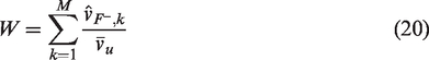
Thermoacoustic oscillations have a low amplitude initially during which the linearity of the flame response plays a leading role. Unstable mode will grow in perturbation amplitude until nonlinear effects become sufficiently important to achieve a limit cycle. At the nonlinear stage, if acoustic systems inside different burners are not identical due to some random factors (e.g. a large intensity disturbance occurs somewhere inside the annular combustor), the azimuthal mode will be strongly affected by this symmetry modification (for the saturation model, the difference of velocity disturbance immediately before each flame will not lead to the symmetry breaking when the heat release disturbances are in the linear response stage). The sum of the fractional velocity perturbations immediately before M flames is denoted as W which can be considered as an indicator of the oscillation development stage, expressed as
Taking
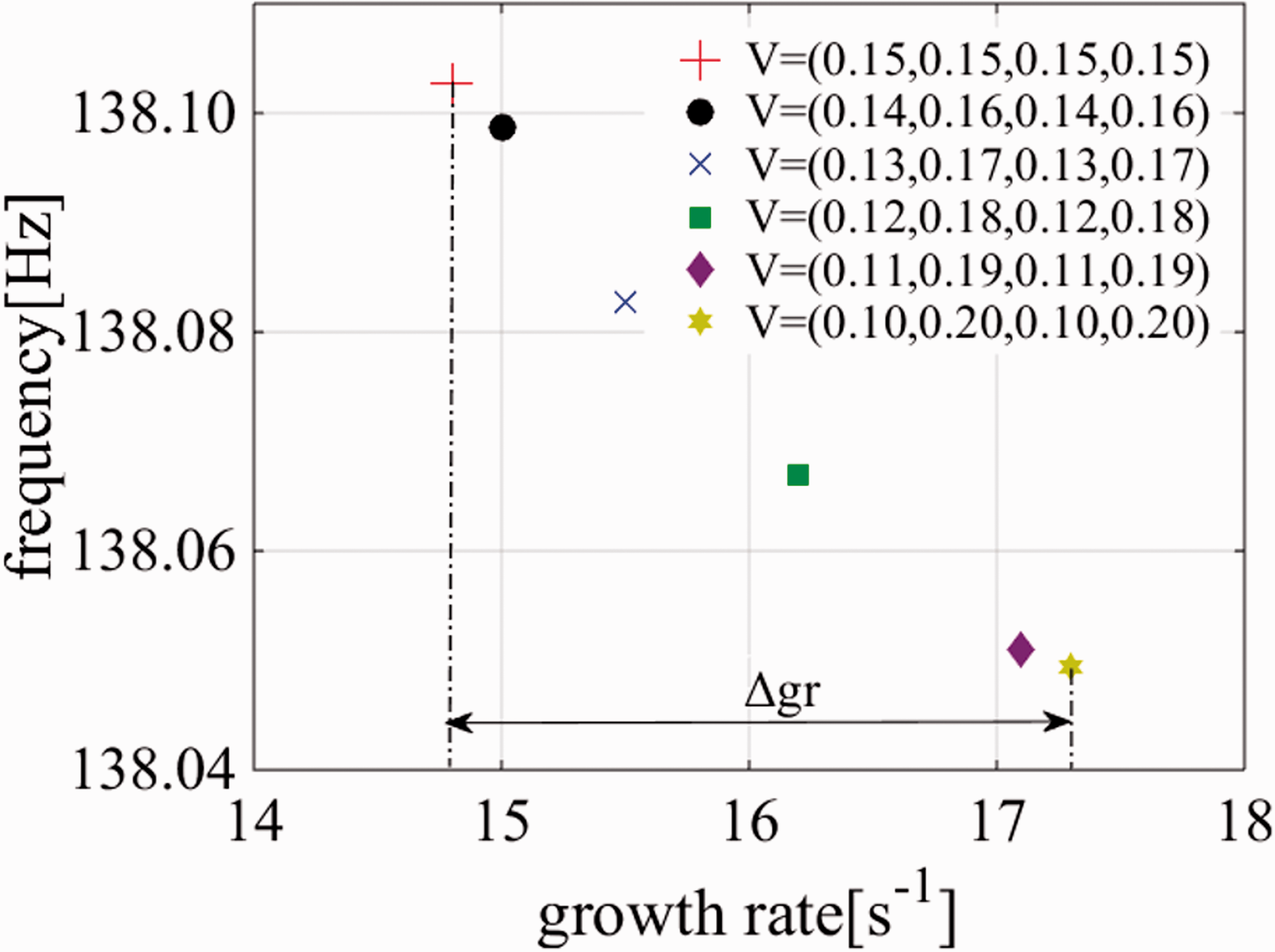
Modal frequencies and corresponding growth rates of the unstable mode of axisymmetry and non-axisymmetric cases for a fixed value of
Feedback control of azimuthal combustion instabilities
OLTF for control purposes
The OLTF for control purposes is from the voltage signal 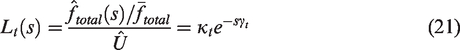
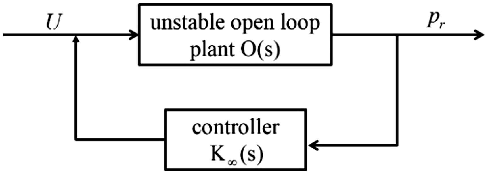
Block diagram of the feedback control system.
The NFTFs have the form expressed as equation (17) when the controller is turned on. Substituting equation (17) into equation (13) in Bauerheim et al.
13
and after a series of derivations, the following expression can be obtained

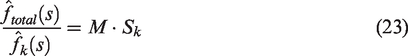
Combing equations (21) to (23) then gives the modal OLTF 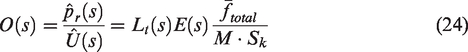
Due to the flame nonlinear response and the symmetry breaking of the azimuthal thermoacoustic modes,
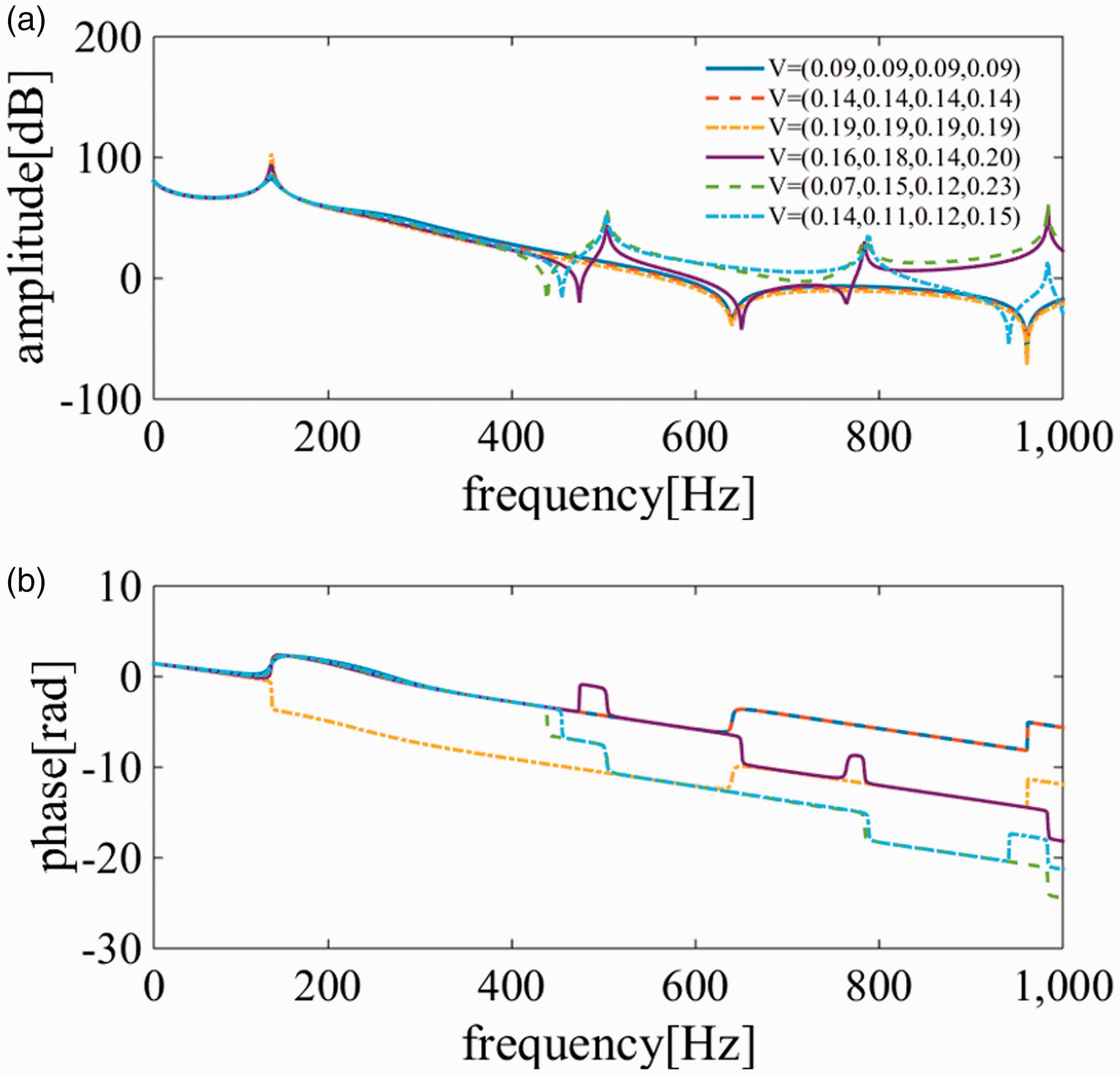
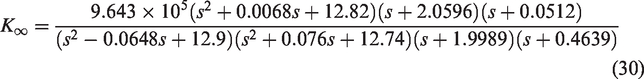
Bode plot of the
By assuming each mode to be described as a second-order transfer function, the stability of the system can be assessed by checking the phase change across the peaks.
3
A 180° phase increasing across a peak indicates an unstable conjugate pair of poles while a 180° phase decrease indicates a stable conjugate pair of poles.
11
From Figure 7, the plant of
loop-shaping and the
metric
loop-shaping
The The OLTF A stabilizing controller If
metric
The difference between two open-loop plants can be measured by the 
The
Controller design
Due to the flame nonlinearities introduced by the NFTF, the OLTF varies with the fractional velocity perturbations immediately before the M flames
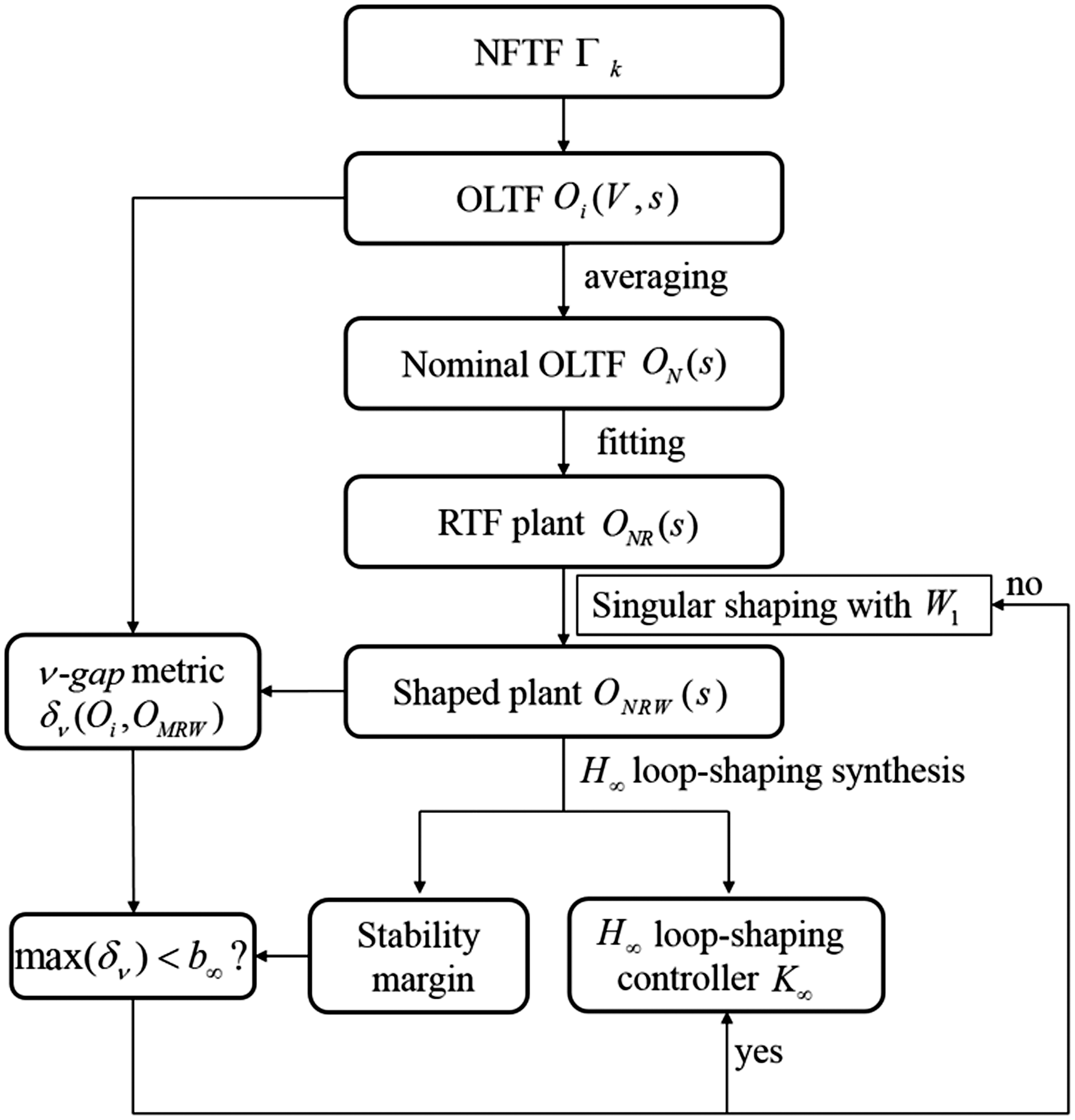
Block diagram of the feedback controller design process. NFTF: nonlinear flame transfer function; OLTF: open-loop transfer function; RTF: rational transfer function.
From Figure 4, flame nonlinearity acts when
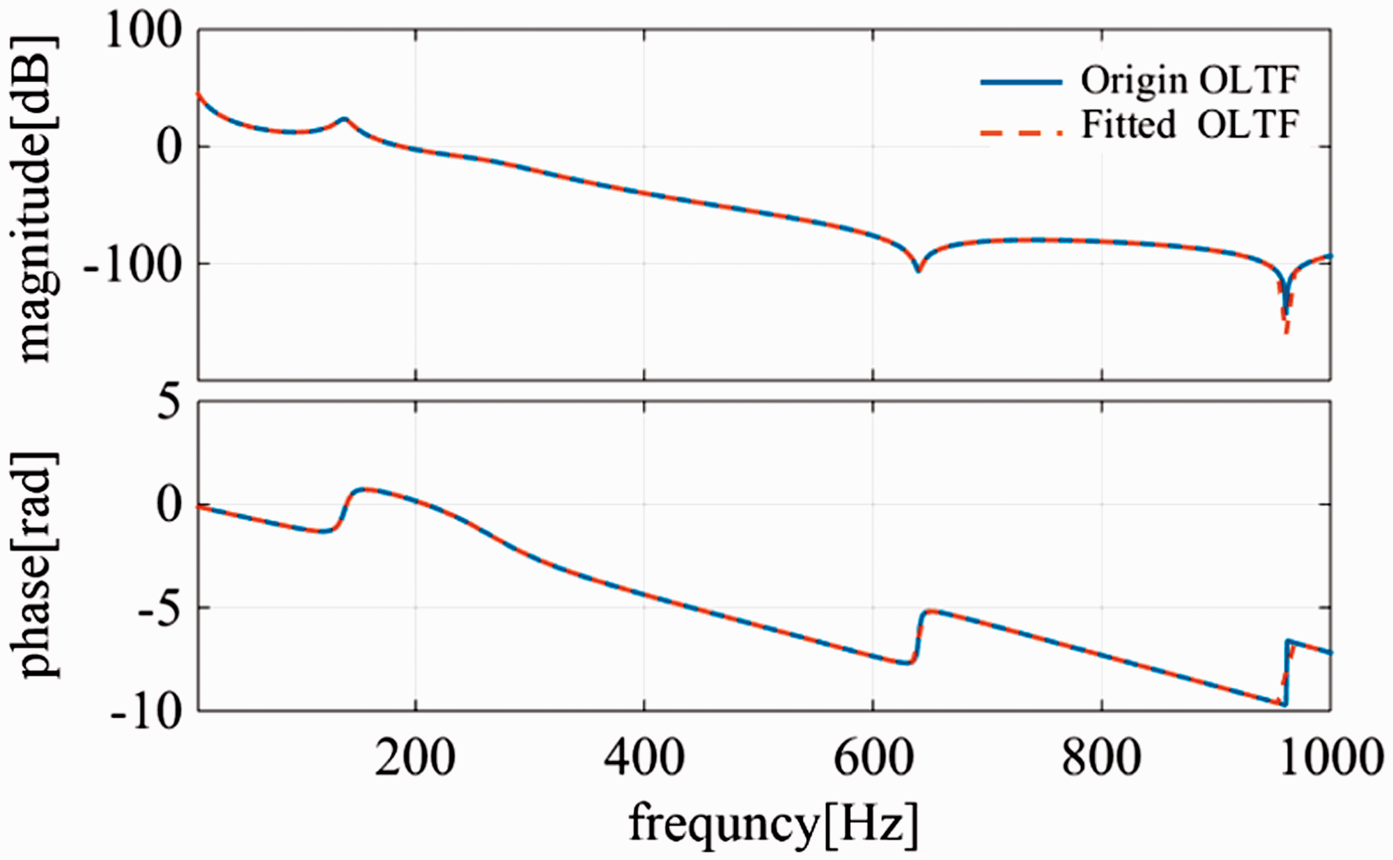
Comparison between the original OLTF and fitted OLTF (high-order fitting). OLTF: open-loop transfer function.
The
The fractional velocity perturbations
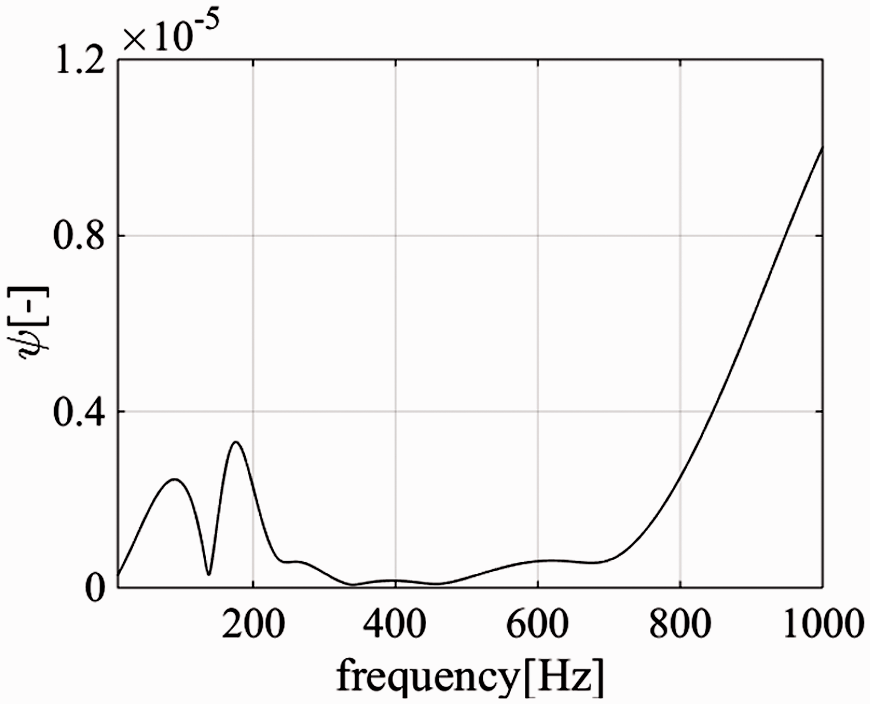
Plot of
The selection of the compensator governs the 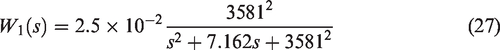
After shaping the singular value of the fitted nominal plant
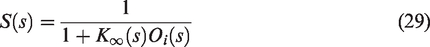
The closed-loop transfer function has the form as equation (28). If any isolated closed-loop pole locates in the right half plane, the system is unstable. On the contrary, the system is stable when there is no isolated closed-loop pole located in the right half plane.
11
Then same open-loop plants 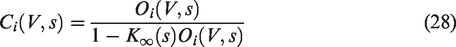
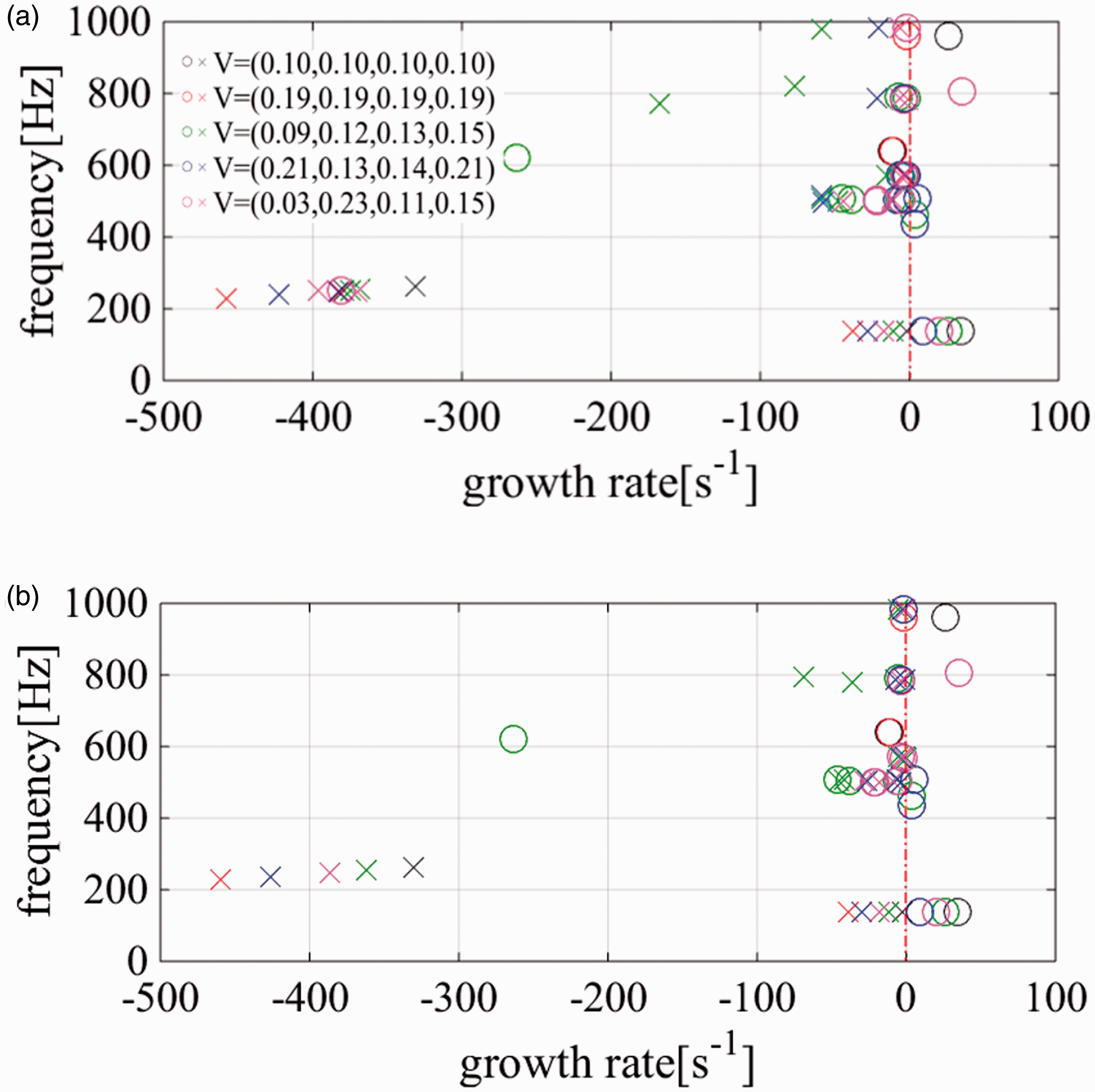
Pole-zero plot of the closed-loop transfer function for five typical cases of V. (a) High-order controller and (b) low-order controller. The circle represents the zeros and the cross represents the poles.
When the heat release rate oscillations grow sufficiently large, limit cycle oscillations are established and the corresponding OLTF seems to be stable even without feedback control. Under this condition, sensitivity transfer functions could be used to measure the performance of the controller
7
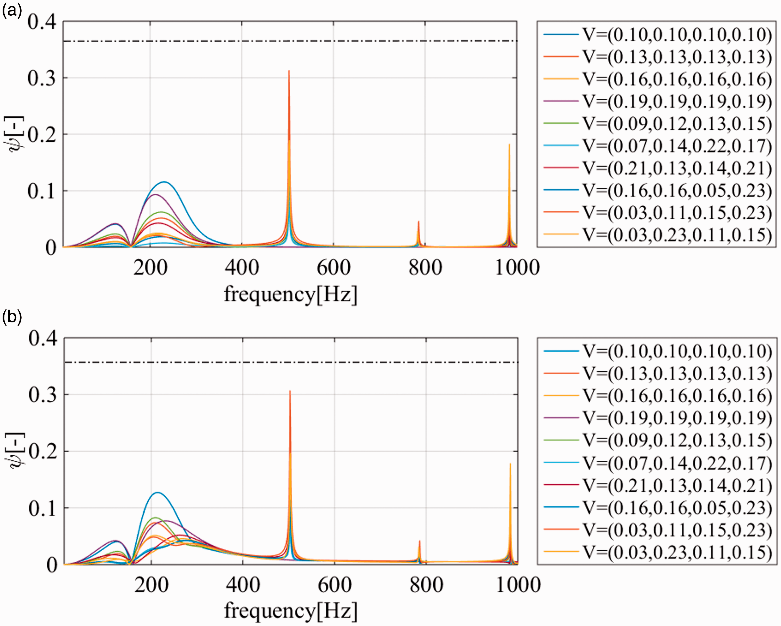
When the sensitivity function is smaller than 1, the feedback controller can attenuate the disturbances. The limit cycle oscillation states are not unique due to the consideration of symmetry breaking. Figure 13(a) shows plots of
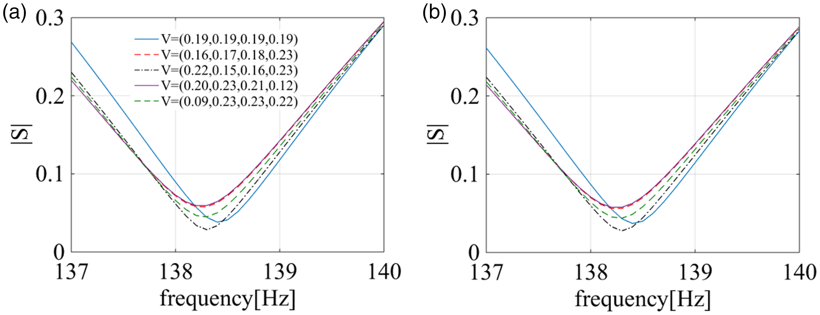
Plots of
Low-order
controller design method
A
A four order RTF is used to fit the original plant. As shown in Figure 14, the low-order RTF is well fitted at the low-frequency range and has larger deviations at high frequencies than the high-order fitted RTF. Same as high-order controller design procedure, 10,000 OLTFs
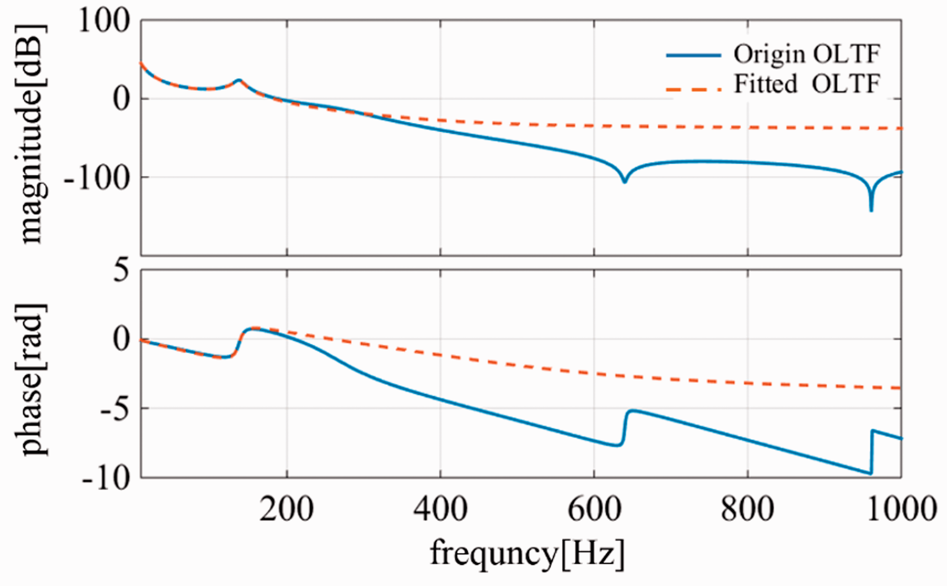
Comparison between the original OLTF and fitted OLTF (low-order fitting). OLTF: open-loop transfer function.
The same weights as equation (27) are used to reshape the low-order fitted nominal plant. The final controller has an order of 6 in the denominator and 4 in the numerator
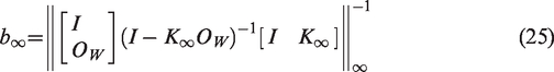
The robust stability margin
Conclusions
In this work, a theoretical annular combustion chamber model is improved by taking into account the effects of the flame nonlinearity, the bulk fluid flow, and the viscothermal wall damping mechanisms inside the burners which are ignored in the original model for the sake of simplicity. This improved model is used to predict the azimuthal combustion instability and develop the corresponding model-based active control strategies for the annular combustors. A pressure transducer mounted on the plenum is used as the sensor and a valve on the fuel feed line as the actuator.
The nonlinear response of the flame to the flow disturbances is modeled using a simple gain/time delay model with saturation bounds. The NFTF may vary depending on the flow disturbance levels, and the NFTF within each burner may therefore be different since the flow state in each burner can be different. It is obvious that the OLTF of the controlled system is not unique, and one of them is selected and then fitted to obtain a nominal OLTF (RTF) for controller design.
The distances between all the possible OLTFs and the nominal OLTF are measured using the
Footnotes
Declaration of conflicting interests
The author(s) declared no potential conflicts of interest with respect to the research, authorship, and/or publication of this article.
Funding
The author(s) disclosed receipt of the following financial support for the research, authorship and/or publication of this article: This research was supported by the National Natural Science Foundation of China (Grant no. 51806006).