
Abstract
Experimental measurement of transmission error and vibration of a gear pair with crown modification are developed. With the help of high-precision optical encoder, effects of gear misalignment on unloaded and lightly loaded dynamic transmission error, which are relative to gear rattle, are investigated. The gear mesh misalignment is introduced by eccentric sleeve assembled on the output shaft. Effects of modification and misalignment on the dynamic transmission error, are studied at different load and driving velocity conditions. The experimental results show that, with the increase of the crown amplitude, the peak-to-peak values of dynamic transmission error are decreasing dramatically. Impact deformation or elastic deformation is a very important part of the dynamic transmission error although they are unloaded or lightly loaded. The components in harmonics of meshing frequency will change distinctly comparing cases at low input shaft velocity without and with misalignment, but different phenomena are detected while increasing the input shaft velocity. Finally, the relation between transmission error and gear box vibration is illustrated, and spectrum kurtosis is introduced to reveal gear rattle.
Introduction
Gear noise is normally divided into two parts as gear whine and gear rattle. Lightly loaded gears have been introduced to exhibit nonlinear behaviors when the surfaces of the gear teeth loose contact and later collide. Rattle can be excited by external speed fluctuations or internal gear excitation such as transmission error.
An overview of transmission error measurement techniques and corresponding demodulation methods are presented in Sweeney and Randall. 1 The four major factors that affect the loaded dynamic transmission error (DTE) are: (a) tooth geometry errors, (b) elastic deformation, (c) imperfect mounting, and (d) less common factors (such as geometric variations due to temperature and high-speed operation; inappropriate lubrication, and high-speed dynamic instability). Two measurement methods are used, which are angular accelerometer based and rotary encoder based. In order to measure the transmission error in gears, the techniques based on the use of optical encoders have been applied in the experiments of gear rattle or impact.2–9
Henriksson and Pang5,6 measured the DTE and noise of a truck gear box. The coupling and correlation between noise and DTE are investigated. Their study emphasized the need to consider transmission error as gear noise excitation while designing quiet gears. By using the optical encoders based technique, Russo et al. 10 and Rocca and Russo 11 investigated the influences of the lubricant and center distance of gear pairs through measuring the relative teeth motion. In order to discriminate the different behaviors regarding the gear rattle phenomena, an index, “gear rattle index”, have been proposed in their analyses.
Ottewill et al.12–14 evaluated the influence of gear eccentricities and small tooth profile errors on the dynamic behavior of a slow running and unlubricated spur gear pair. In their papers, through harmonic analyses and substitutions into the theoretical model, they proposed an identification methodology, starting from an experimental acquisition under constant speed, which deduced the accordance with experimental results. But in the case of misalignment between the gear and shaft center, agreement was less good, which needed further study to understand the effect of misalignment on the DTE, especially for gear impact pattern. In the existing references, most work focused on analytical studying of the gear mesh misalignment’s effect on load distribution and contact or bending stresses. For gear mesh misalignment, it may result in shift of the load distribution to a gear pair that results in the increase of contact and bending stresses, moving the peak bending stresses to the edge of the face width (namely partial contact), and might also increase gear noise. 15 Toshio et al. 16 studied the effect of misalignment on gear vibration experimentally, and the relation between the characteristics of helical gear vibration and the parallelism of the axes have been investigated and frequency analyses of gear vibration signals were carried out by measuring the acceleration level. The gear vibration in the rotational direction and the bearing vibration of a helical gear with different lead errors were measured by Park and Lee. 17 They found that the gear vibration was significantly influenced by the direction of the lead error. The gears without the lead error had less vibration than those with the lead error, and proper lead modification could reduce the gear vibration.
The main work of present research is to study the unloaded or lightly loaded gear transmission error experimentally, which is relative to gear rattle. Firstly, a test rig is set up with different kinds of crown modified spur gears. The gear mesh misalignment is introduced by eccentric sleeve assembled on the output shaft. Effects of modification and misalignment on the DTE are studied at different load and driving velocity conditions. The relation of transmission error and gear box vibration is also studied, and the spectrum kurtosis is introduced to reveal the gear rattle.
Experiment measurement
Test rig
The experimental test rig comprised of a pair of spur gear is shown in Figure 1. The design data of the tested gears are presented in Table 1. The gears used in this experiment are precision grounded to satisfy DIN Grade 6 standard. Once having been manufactured, the maximum profile error, the maximum tooth to tooth error, the maximum tooth alignment error, and the maximum total composite profile error are determined. In order to investigate the effect of misalignment on the lightly loaded gears’ transmission error and gear rattle, three cases of gear crown modification were adopted as listed in Table 1. The crown modification is along tooth width direction, as shown in Figure 1(c). Symbols δ and b are the crown amplitude and tooth width, respectively.
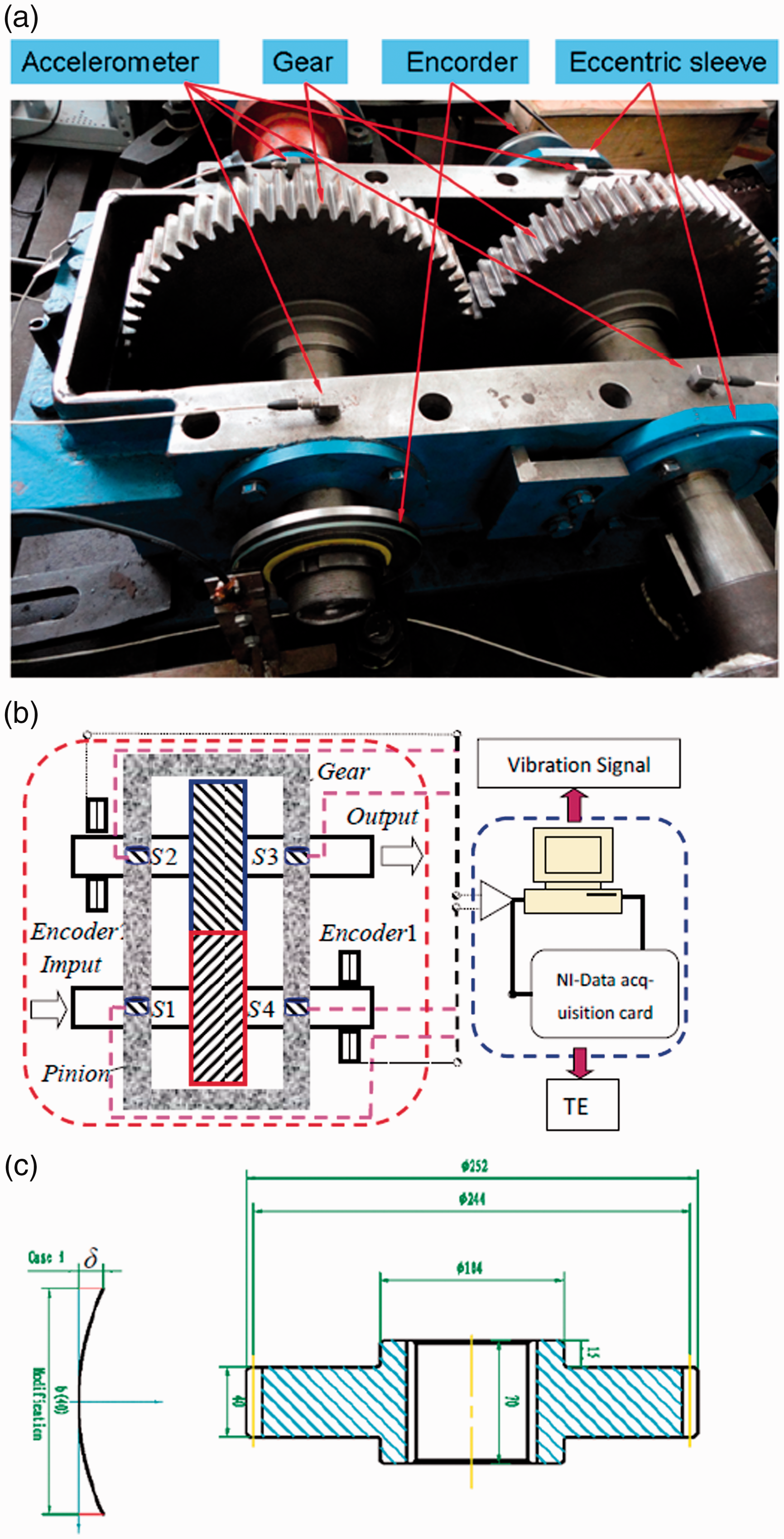
Test rig of gear transmission system: (a) 1:1 meshing gear pair; (b) illustration of the data acquisition of vibration and transmission error; (c) the shape of modified gears.
Design data of gears.
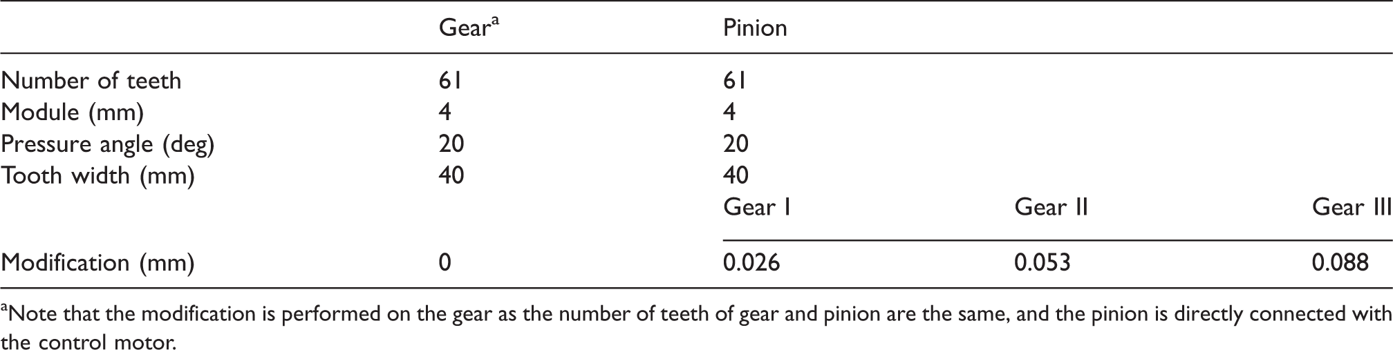
aNote that the modification is performed on the gear as the number of teeth of gear and pinion are the same, and the pinion is directly connected with the control motor.
The gearbox is powered by an electrical motor, which is capable to speed up to 3000 r/min. The torque breaking the gearbox is applied by a magnetic brake. Two analog output encoders (Mercury 1000: fundamental counts per revolution (CPR) are 16,384) have been fixed to the end of two shafts. A data acquisition board (NI.PCI 6132 4 I/O channels, 2.5M), installed in a personal computer and programmed in NI.LabView environment, performs a buffered reading of the signals from the two encoders. As the maximum limit speed of encoder is 1318 r/min, the measurement is performed from 50 to 1200 r/min approximately. Additionally, the center distances of gears can be adjusted by the eccentric sleeve installed on the output shaft as shown in Figure 1(a). Gear mesh misalignment can also be achieved.
Measurement method
Two encoders’ original output is standard analog sine/cosine output, as illustrated in Figure 2. When the assembly errors of hubs with encoders are neglected, one can use the intersect point with time axis to scale the difference of rotation angle positions. Namely, in the interval 
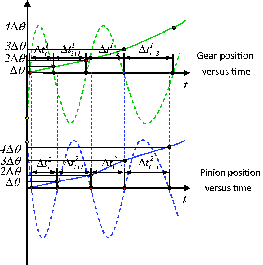
Illustration of gear and pinion position versus time.
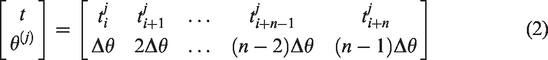
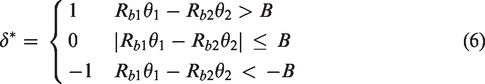
Then the rotation angle of gear and pinion versus time are described as
As mentioned above, the main precision of the measurement is determined by the fundamental CPR and calculation method at intersected point. And the first one is prior determined by the encoder. To overcome this issue, the interpolation method is performed after obtaining the original data. Among interpolation techniques, piecewise cubic hermite interpolation has the most efficiency as it tackles original signals with high fluctuations and less smoothness. 18
The transmission error of a gear drive is defined as the difference between the position where the output shaft of a gear drive would be when the gear sets are perfect, without errors or deflections, and the actual position of the output shaft.
19
According to the definition, the loaded transmission error (LTE) can be represented as

Here, R is the ratio of the number of teeth in the output gear to that in the input gear.
Experiment investigation
In these sections, the effects of assembly error, load and velocity on the DTE especially for gear rattle are investigated experimentally.
Effect of velocity on the gear rattle
At first, the gear pairs are assembled with standard center distance, we applied none load on the output shaft, and the gear’s velocity is 199.5 r/min approximately. A comparison of the DTE of the three gear pairs, Gear I to Gear III, is shown in Figure 3. In these figures, the original DTE is denoted by red line and DTE that filtered out the shaft frequency component is denoted by blue line. The DTE are almost sinusoidal, but the PPV are much different. With the increase of the crown amplitude, the PPV are found to decrease dramatically, as shown in Figure 5. The main focus of this study is the meshing frequency and the impact deformation component transmission error, and so the shaft frequency component can be disregarded in this subsection. Although there is no load applied to the gear set, the first two harmonics of transmission errors are still visible above the noise floor as shown in Figure 4, which are different from the results given by Wright 20 and Hotait Kahraman, 21 where the first harmonic of transmission error is not visible above the noise floor under no-load condition. The main reasons for this phenomenon may be: (1) although no load is applied, the viscous load abducted by bearing and friction still exists, and the effect decreases with the increase of the driven velocity as found in the test. (2) Additionally, the geometry errors made by manufacturing imperfections are inevitable and the most important factors which influence gear meshing pattern. These geometry errors may also cause the fluctuation for the first harmonic component of transmission error. (3) Elastic deformation 1 is inevitable due to the existence of impact backlash when there is no load applied. While reducing the input velocity to 100.8 approximately, the impact parts are prominent as shown in Figure 5. When the two cases are present, there is less change in the second harmonic component of transmission error virtually. But the first harmonic component increases dramatically from 5.064 × 10⁻⁶ rad to 2.668 × 10⁻⁵ rad for Gear I.
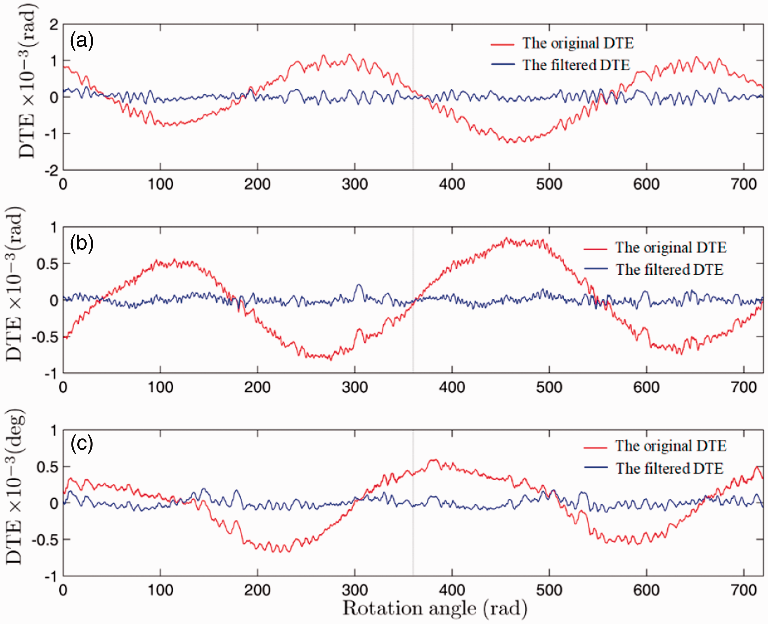
The original DTE is denoted by red line in gear transmission system: (a) Gear I, (b) Gear II, (c) Gear III verse rotation angle within two revolutions. DTE that filtered out the shaft frequency component are denoted by blue line. No load is applied and the velocity of pinion is approximately at 199.5 r/min and the gear pairs are assembled with standard center distance.
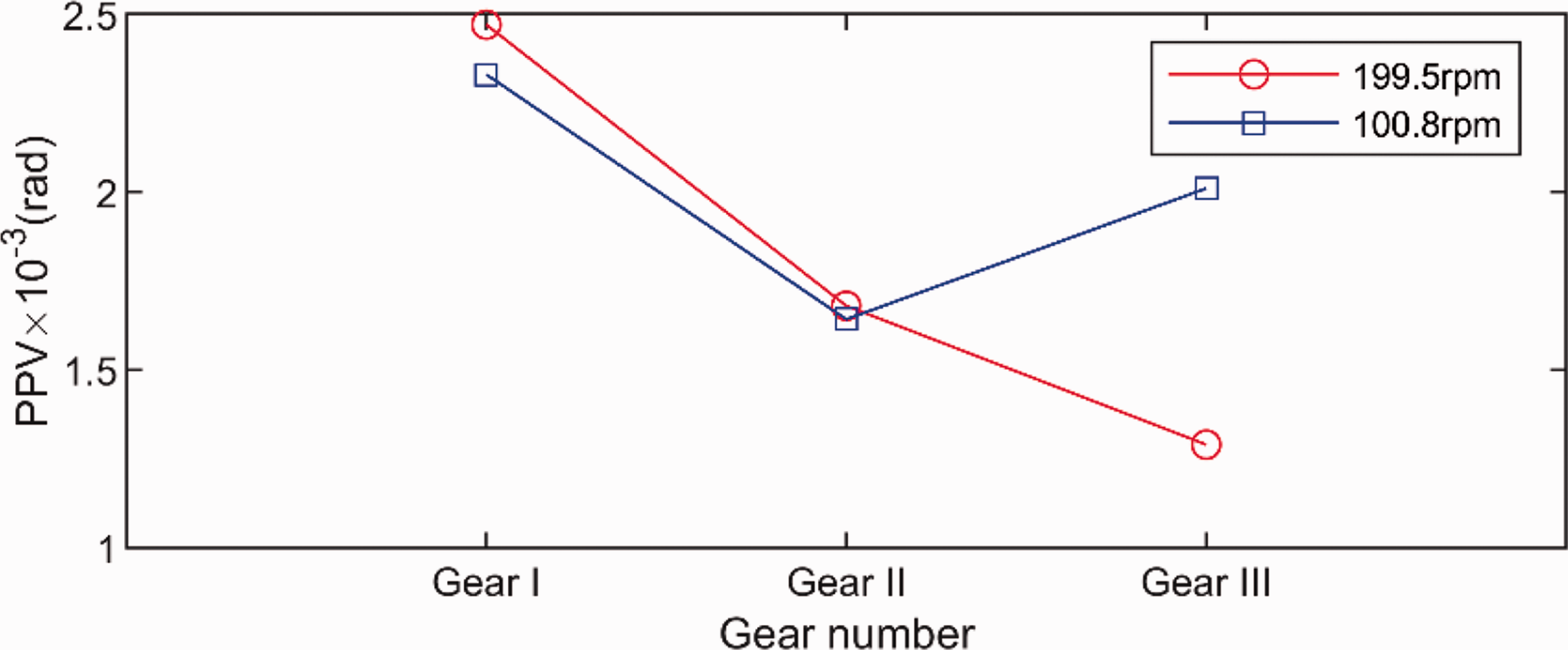
The PPV of DTE of Gear I, Gear II, and Gear III under different velocities.
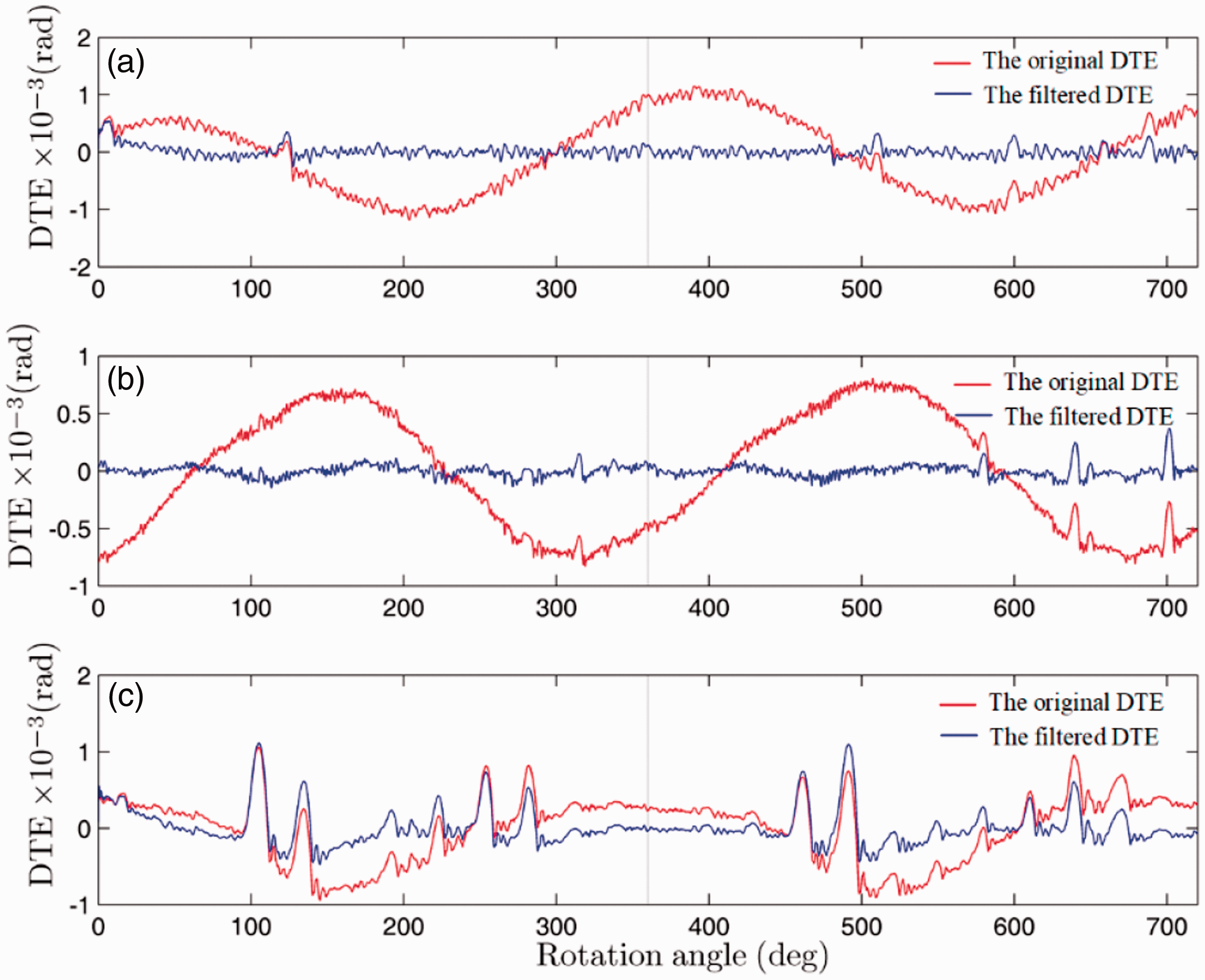
The original DTE is denoted by red line in gear transmission system: (a) Gear I, (b) Gear II, (c) Gear III verse rotation angle within two revolutions. DTE that filtered out the shaft frequency component are denoted by blue line. No load is applied and the velocity of pinion is approximately at 100.8 r/min and the gear pairs are assembled with standard center distance.
To analyze this elastic deformation, the impact of meshing gear teeth can be approximated by two spatial curved surface parts
22
when the gear’s crown modification is considered. The principal radii of curvature of the part i(i = p,g) are 
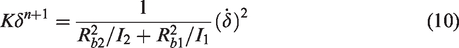
The dynamic equation of gear meshing impact can be written as
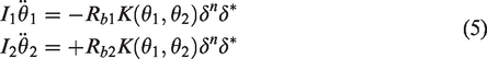

Note that, in this paper, we focus on the maximum effect of the impact on transmission error and energy disappearance or impact damping, but the influence of meshing friction is not included. So we can simplify the dynamic equation (5), and consider the interval when two gears mesh are together. Then

Multiplying 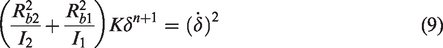
Or
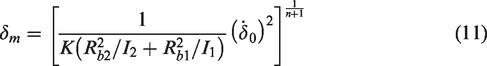
By using the Runge–Kutta numerical method with event-driven schemes,
24
the numerical results of DTE are shown in Figure 6 with no load and input velocity at 200 r/min. The gear parameters are the same as that in the test rig. In Figure 6(a), the red “>” points indicate the two meshing gear tooth impact at the moment; meanwhile, the initial impact velocity
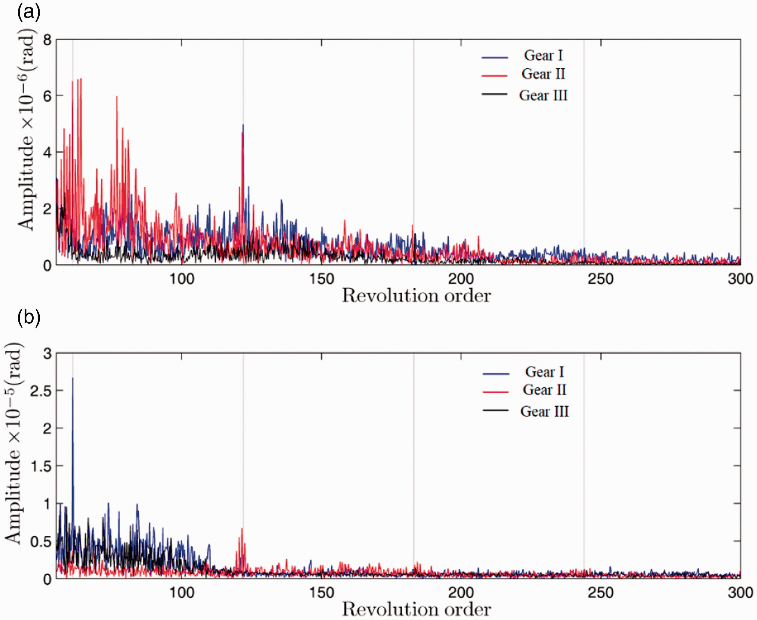
Spectrum of DTE for Gear I, Gear II, and Gear III are denoted by blue line, red line, and black line, respectively. With input velocity (a) 199.5 r/min and (b) 100.8 r/min, the revolution order is determined by comparison with the input shaft velocity.
Although the impact is the feasible interpretation for the knicks presented in the experimental transmission error, from the experimental viewpoint, it is a key problem for our future research to obtain the impact velocity or the corresponding deformation.
Effect of gear misalignment
In this section, we will focus on the effect of gear misalignment on the gear rattle, and the comparison of DTE, spectrum, and corresponding previous third harmonics components of transmission error are illustrated subjected to different modification parameters, respectively. To begin the analysis, the input shaft velocity and load are set to be 50 r/min and 30 Nm, and the gear pair is assembled with the standard center distance. The DTE (a), spectrum (b), and harmonic amplitudes (c) for Gear II are indicated by the black line in Figure 7. Then by adjusting the eccentric sleeve, the gear misalignment is introduced, as shown in Figure 8, and the experimental results indicated by the red line are shown in Figure 7. It shows that the peak-to-peak value of DTE increases in some sort. However, the components of harmonics of meshing frequency change distinctly; in Figure 7(a) the comparison of the first three harmonic components is illustrated. When increasing the input shaft velocity to 1200 r/min, the same conclusions are obtained as shown in Figure 9. In addition, Gear III is tested with the same conditions as above, and similar phenomena are detected and detailed experimental curves are not shown in this paper. But detailed relations of DTE and gear set vibration are analyzed in the following subsection.
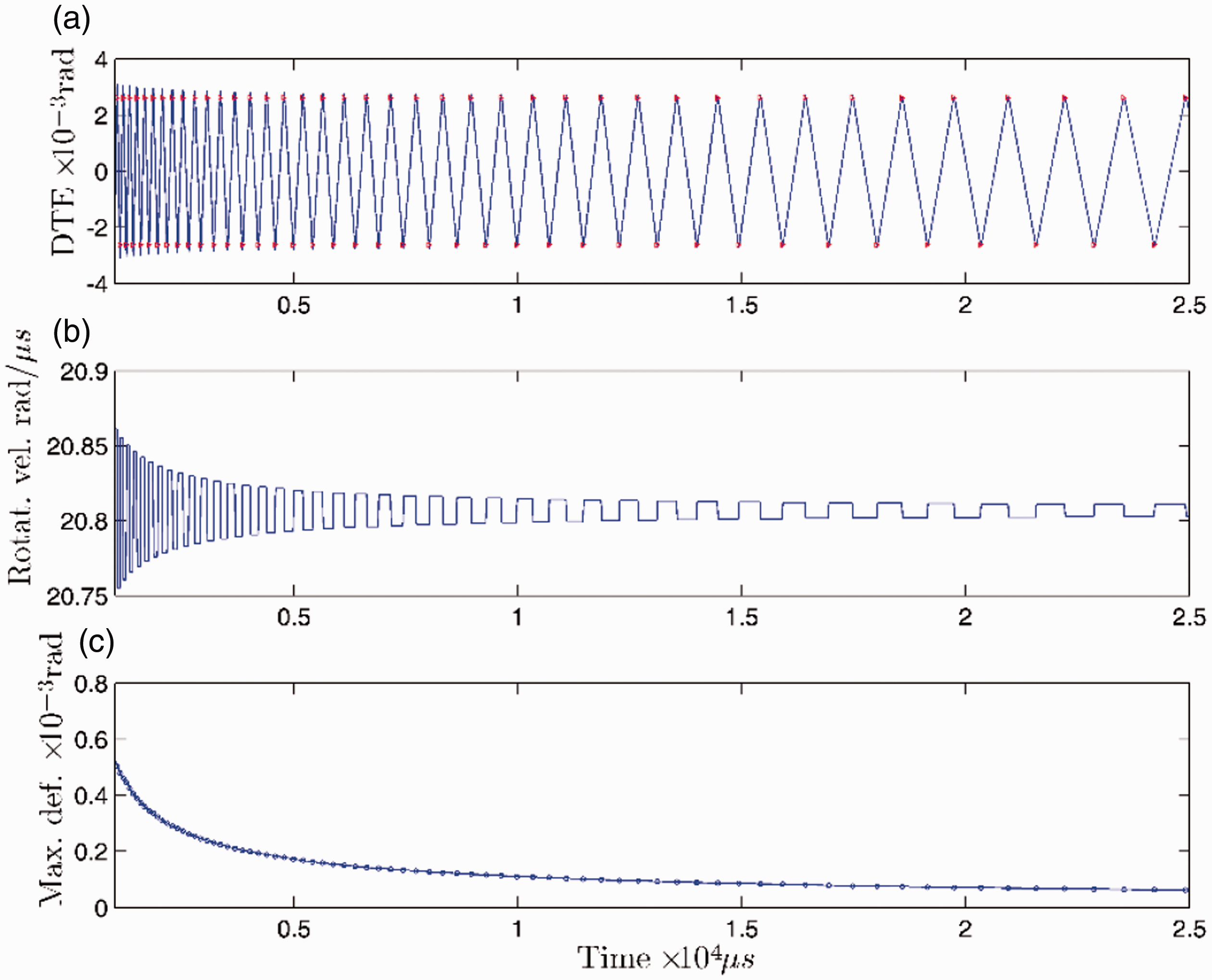
Numerical results of DTE: (a) with the same initial conditions as experiment, no load applied and input shaft velocity approximately at 200 r/min; (b) varying rotation velocity of pinion; (c) the maximum deformation (Max. def.) deduced by the impact.
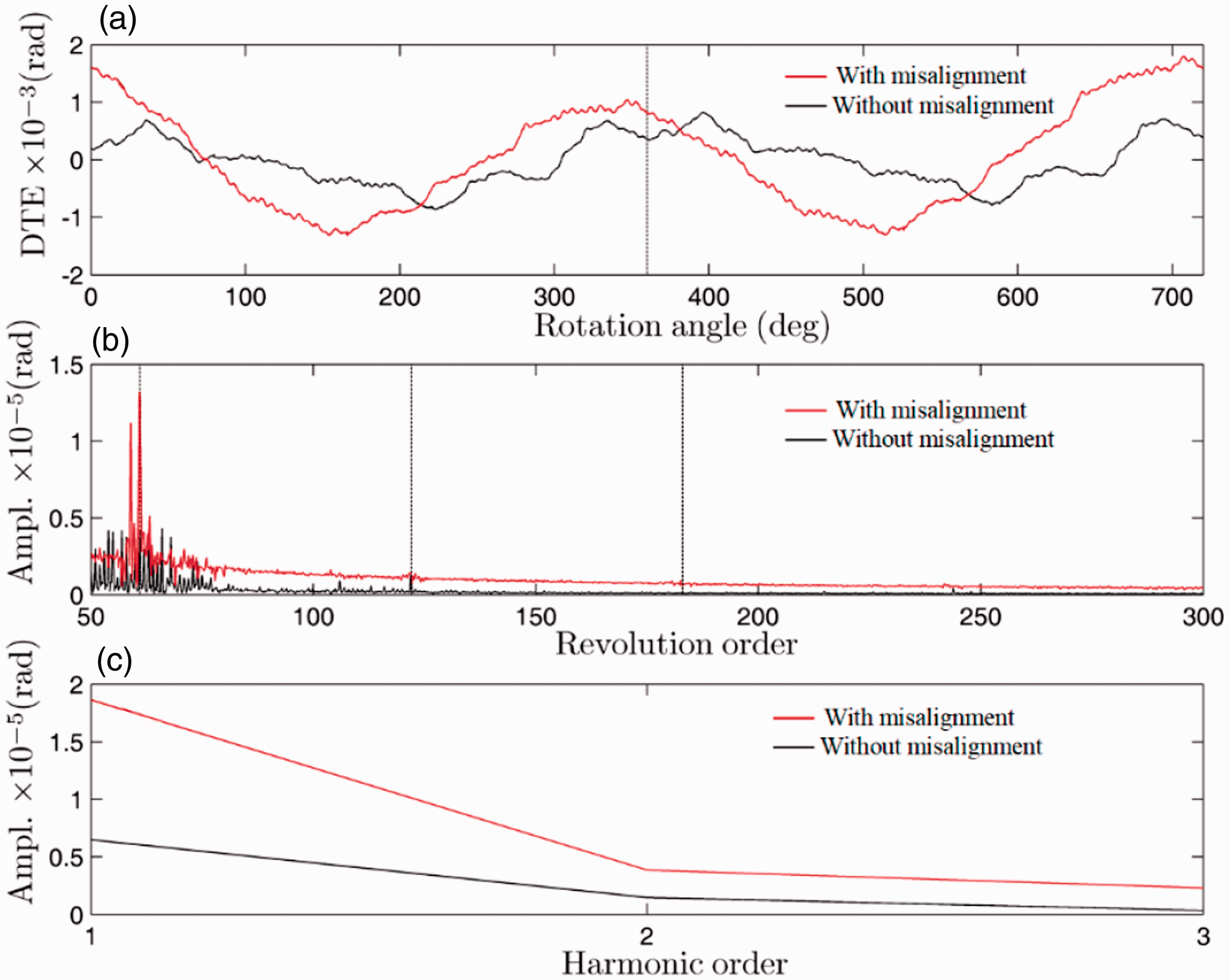
(a) DTE, (b) spectrum, and (c) harmonic amplitudes for Gear II with and without misalignment are denoted by red and black lines, respectively. Input velocity is at 50 r/min and the load applied is 30 Nm.
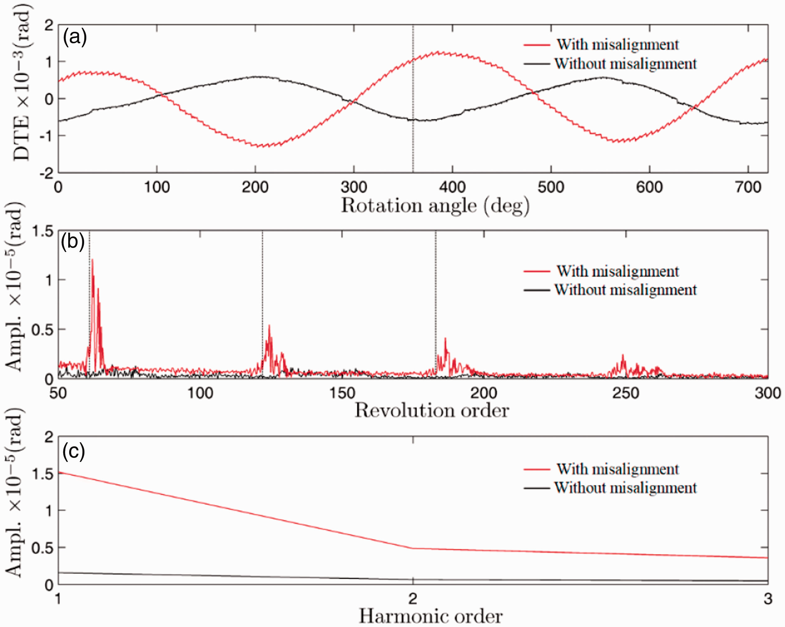
(a) DTE, (b) spectrum, and (c) harmonic amplitudes for Gear II with and without misalignment are denoted by red and black lines, respectively. Input velocity is at 1200 r/min and the load applied is 30 Nm.
Effect on vibration
In the first of analysis, Gear III is assembled with misalignment. To get the DTE and vibration accelerometer signals, no load is set on the rig and the input shaft velocity changes from 50 to 1150 with step 100. The first three fundamental tooth meshing frequency components and shaft frequency component of DTE for Gear III are shown in Figure 10(a) and (b), respectively. In Figure 10(a), the first three components are denoted by black, red, and blue lines, respectively. These curves show that the shaft frequency increases linearly in accordance with input velocity, but the first fundamental tooth meshing frequency component rises to the highest at 150 r/min and then fluctuates with the increase of the input shaft. They are coincident with gear rattle noise when input shaft velocity is below 200 r/min approximately. But when we turn out to vibration signal, the waterfall spectrums and corresponding enveloping spectrum are illustrated in Figure 11(c) and (d), respectively. The differences of the tooth meshing frequency components (as shown in Figure 11(e)) are not obvious. To understand these, one must be clear that, firstly, the vibration from contact or impact area must be transferred through gears, shaft bearings, and cases until reaching the accelerometer. Consequently, the broadband vibration may be modified considerably by transfer function between the gear teeth and accelerometers. 25 Secondly, the transmission error and vibration signal are scaled by angle displacement (rad) and acceleration g, respectively. Finally, there is much noise included in the vibration signal, which is determined by the accelerometer and measurement circumstance. Consequently, we add 30 Nm torque to the output shaft, and the experimental results are shown in Figure 12. As can be seen, the first three fundamental tooth meshing frequency components increase distinctly, as shown in Figure 12(a), and still the first tooth meshing frequency is the major part. It is interesting to note that the shaft frequency components have different trend when load 30 Nm torque is applied. Those within 0.90 × 10⁻³ rad to 1.20 × 10⁻³ rad are shown in Figure 12(b). As for the vibration signal, the first tooth meshing frequency component with 30 Nm load is much higher than that without unload as shown in Figure 11(c) to (f). This means that without drag load, the gear impacts each other with impact frequency; the lighter load makes the gear tooth meshing each other, and the impact still occurs due to the gear manufacturing error or misalignment. To understand these, spectrum kurtosis26,27 is adopted in our analysis to estimate the gear impact. As the value of kurtosis is sensitive to the dramatic change of signal structure such as impulses, it can be used to estimate strong or weak impact parts in the gear vibration signal. The spectrum kurtosis for the cases without and with drag load is illustrated in Figure 13, denoted by blue line and black dashed line respectively. The Figure 13 shows that the impact occurs.
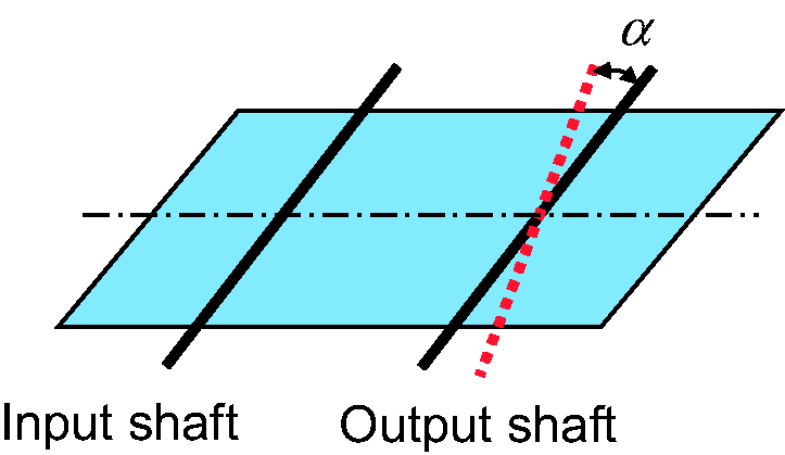
Angle misalignment of the gear transmission system.
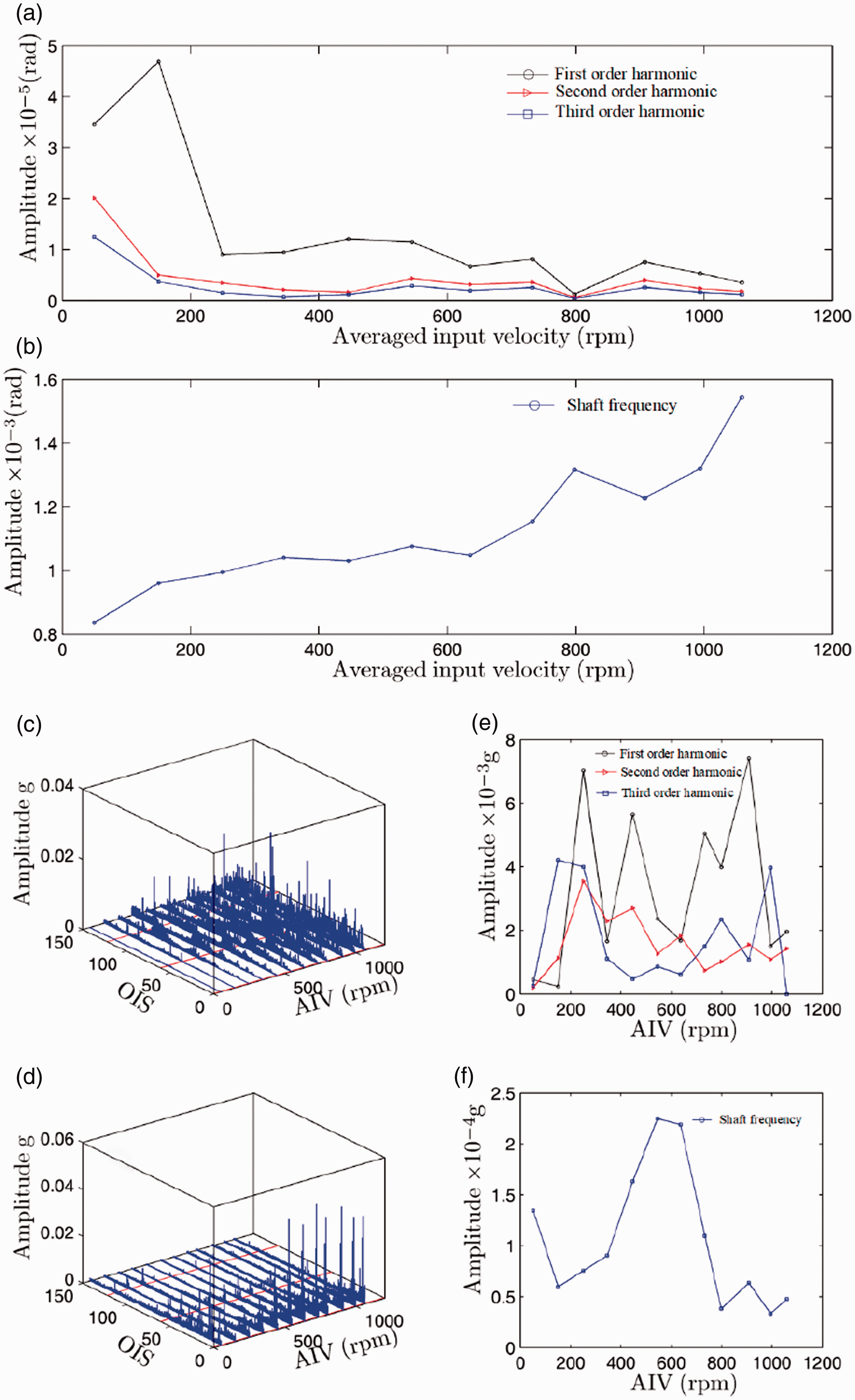
First three fundamental tooth meshing frequency components (a) and shaft frequency component (b) of DTE for Gear III with load 00 Nm. (c) and (d) Corresponding vibration spectrums and enveloping spectrum of averaged vibration signal from the four accelerometers S1–S4. (e) and (f) First three fundamental tooth meshing frequency components and shaft frequency component of the vibration signal.
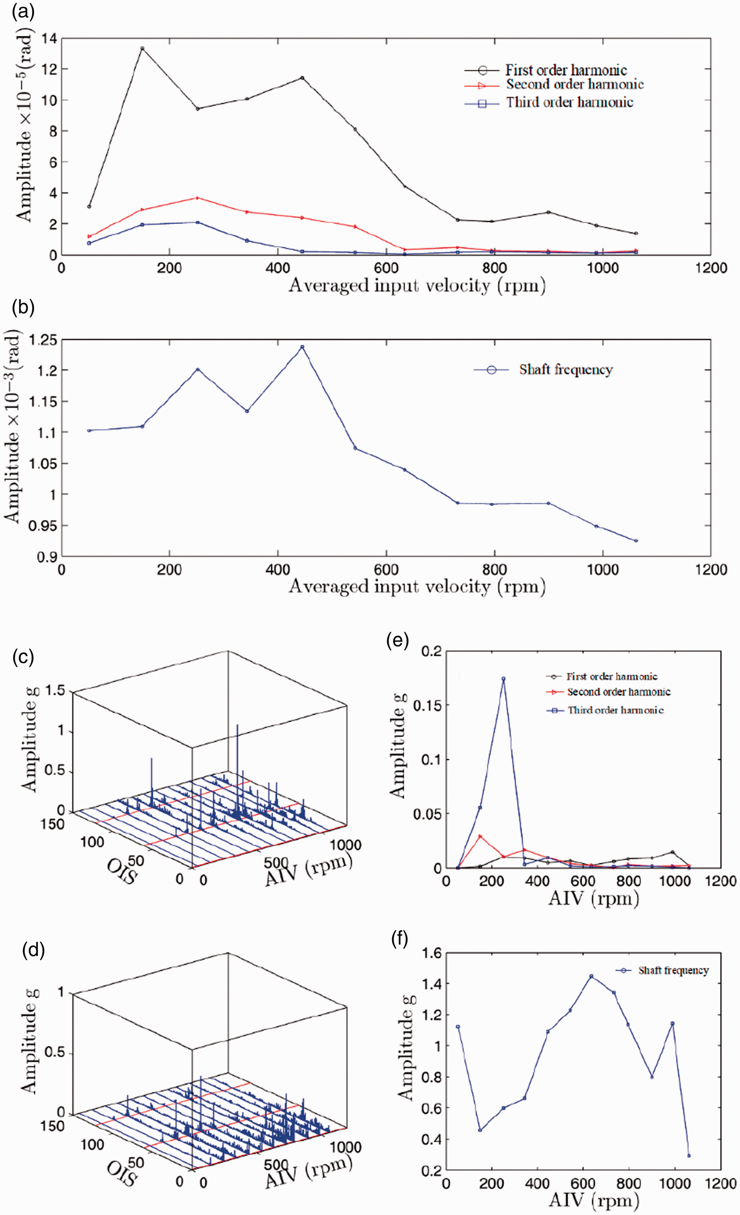
First three fundamental tooth meshing frequency components (a) and shaft frequency component (b) of DTE for Gear III with load 30 Nm. (c) and (d) Corresponding vibration spectrums and enveloping spectrum of averaged vibration signal from the four accelerometers S1–S4. (e) and (f) First three fundamental tooth meshing frequency components and shaft frequency component of the vibration signal.
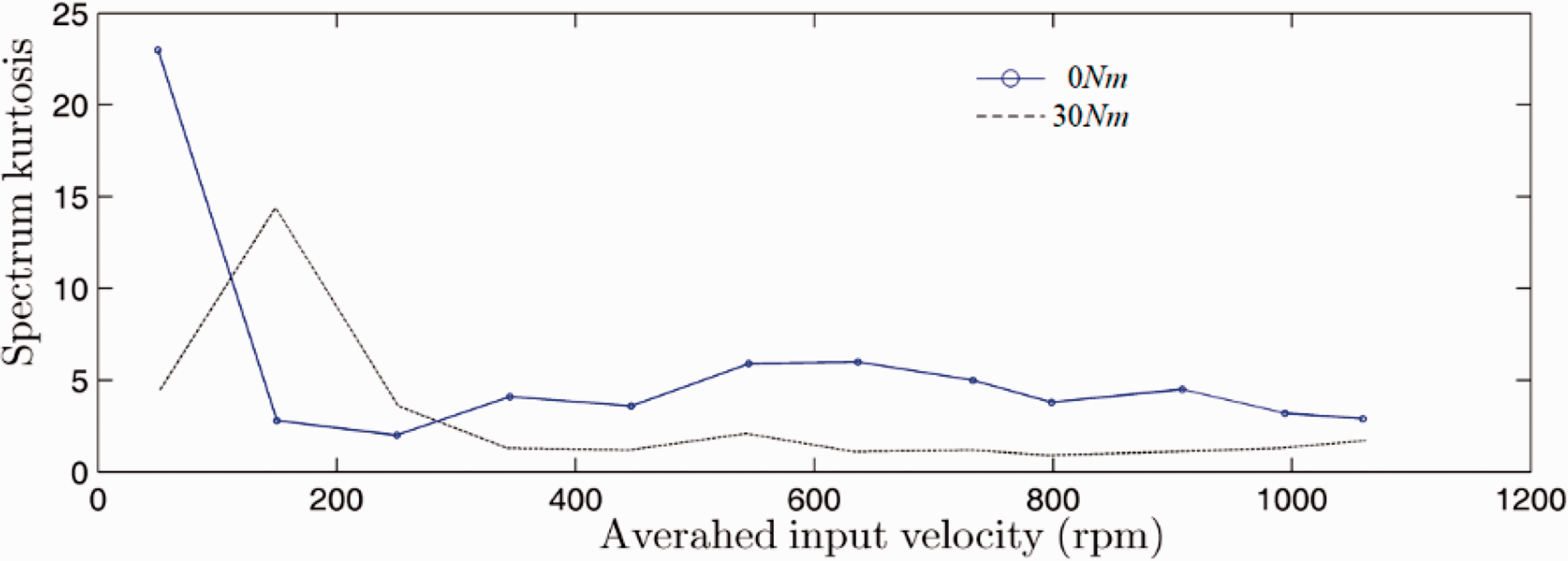
Spectrum kurtosis of the vibration signal with zero and 30 Nm torque denoted by blue line and black dashed line.
Conclusions
How misalignment affects the gear dynamic transmission characteristic are intractability problems for designers. In this paper, effects of gear misalignment on unload and lightly loaded DTE, which is relative to gear rattle, are investigated. Measurement of transmission error, with the help of high-precision optical encoder, and vibration of a gear pair with three kinds of crown modifications are performed. The experimental tests show that:
With the increase of the crown amplitude, the PPV of DTE decreases dramatically when assembly error exists. Theoretical analysis and experimental results indicate that impact deformation or elastic deformation is very important part of the DTE, although they are unloaded or lightly loaded; The components at harmonics of meshing frequency will change distinctly when compared between cases at low input shaft velocity without and with misalignment, but different phenomena are detected while increasing the input shaft velocity. The relation of transmission error and gear box vibration is illustrated, and the spectrum kurtosis is introduced to reveal the gear rattle.
Footnotes
Declaration of conflicting interests
The author(s) declared no potential conflicts of interest with respect to the research, authorship, and/or publication of this article.
Funding
The author(s) received no financial support for the research, authorship, and/or publication of this article.