
Abstract
The manufacturing/assembly error of machine parts is a key factor that influences the performance and economy of mechanical systems. To achieve high assembly precision and performance on the basis of low manufacturing accuracy and cost, this study primarily optimizes the assembly error of machine parts. First, the small displacement torsor is used to characterize the small deformation between the mating surfaces of parts. Subsequently, to realize the combination of small displacement torsor and tolerance, the small displacement torsor with manufacturing error and assembly deformation is mapped to the tolerance domain. Second, based on the relationship between small displacement torsor and tolerance, an assembly error optimization model is established on the basis of the conventional tolerance-cost model, considering the emergence of manufacturing error and assembly deformation. Third, aiming at the high-pressure rotor for aeroengines, the error optimization design of assembly is carried out developed with the assembly accuracy requirement as the constraint condition, and the total costs of the manufacturing and assembly processes as the objective. The optimization results indicate that the manufacturing error range of each mating surface after optimization changes, from small to large, under the premise of ensuring the product’s performance, which verifies that the difficulty in processing parts is reduced, and that the efficiency of parts processing is also improved. Meanwhile, the relative manufacturing cost after optimization is reduced by 6.79%, which reflects the economic requirements to a certain extent. The content of this article provides the necessary design basis and reference for the realization of high assembly accuracy of mechanical systems, under low cost requirements from the design perspective.
Keywords
Introduction
Owing to the complexity trend of mechanical equipment, and the growing significance of the service environment limitation, the requirements for the general performance of mechanical systems are steadily increasing. Presently, the performance impact analysis of mechanical equipment primarily focuses on the factors affecting the product design and manufacturing stage, and less on the impact of the assembly process on product performance. 1 In industrial production, the workload of the product in the assembly process accounts for approximately 45% of the entire production cycle, and the proportion of the assembly process cost in the total cost can reach 20%–30% or even higher. 2 Therefore, the effective guarantee of mechanical product assembly is one of the best ways to determine the performance of the entire machine.
With the continuous advancements of the market economy and computer technology, several users and enterprises have steadily increased the stringent requirements on the performance of mechanical products. There are several factors affecting the assembly performance of products, which include the design tolerance and manufacturing error of machine parts, as well as the deformation of parts under load in the assembly process. 3 Presently, the influencing factors of product assembly performance are primarily defined by the mathematical expression of geometric elements in their tolerance domain, while the assembly deformation between mating parts is less involved. 4 Cao et al. 5 analyzed the relationship between product function and part tolerance, and effectively constructed the 3D tolerance mathematical model via the Jacobian Torsor theory. Mansuy et al. 6 established the tolerance model of parts with a regular cross-section shape, according to the relationship between geometric variation features and the tolerance domain. Homri et al. 7 utilized the modal decomposition method to analyze the surface profiles of various geometric shapes, and adopted a unified error model to express the size and geometric errors. Liu et al. 8 established the mathematical models of dimensional tolerance, orientation tolerance, geometric tolerance, which promoted the further development of the tolerance modeling theory. Zhou et al. 9 established the mathematical expression of geometric error variation under multi tolerance coupling by adopting the SDT theory, and realized the construction of tolerance model. Rahman et al. 10 applied the homogeneous coordinate transformation theory and multi-body kinematics to the machining center, and then constructed a 3D tolerance mathematical model including the thermal deformation deviation of the part surface. Liu et al. 11 analyzed the deformation of flexible bodies in the assembly process, and then constructed the covariance model of the geometry using mixed polynomials. Ghie et al. 12 constructed the error accumulation model in the assembly process of flexible parts, and elaborated the relationship between product function and multiple influencing factors. Makris et al. 13 analyzed the manufacturing error and deformation of mating parts, and established the precision model for product assembly processes. Marziale and Polini 14 primarily used the homogeneous coordinate transformation to build the geometric tolerance model in the assembly process of parts.
In the manufacturing process of mechanical products, the tolerance analysis of parts is the key to improving product quality and reduce cost. Presently, tolerance analysis primarily considers the tolerance elements of rigid parts as the basic point for simulating the product assembly process, and considers the deformation of flexible parts less. Singh et al. 15 proposed a tolerance analysis method based on computer-aided tolerance analysis, which can help designers to evaluate assembly quality. Hashemian and Imani 16 calculated the influence of flexible parts deformation on assembly deviation via the finite element method. Roy and Li 17 transformed the tolerance information of part surface into design variables, and then realize the tolerance analysis of part surface via the linear programming method. Walter et al. 18 discussed the mathematical formula of tolerance analysis, and combined the concept of quantifier to simulate the effect of geometric deviation on mechanism behavior. Corrado and Polini 19 proposed a novel idea to study the influence of shape error and part deformation on superposition results, based on the latest development of rigid flexible body tolerance analysis. Cao et al. 20 obtained the relationship between tolerance and product function by analyzing the product function under different parts tolerance, and then constructed an effective 3D mathematical model of surface tolerance, using the Jacobian screw theory. Korbi et al. 21 studied the relationship between input and output in the tolerance design of flexible bodies by adopting a statistical theory and numerical analysis method; accordingly, they proposed a tolerance analysis theory, considering the deformation of flexible bodies. Benichou and Anselmetti 22 took the non-rigid body as the object to carry out the tolerance analysis, which considered the thermal deformation and other factors in the assembly process.
It is the objective of designers and enterprises to achieve high assembly accuracy and performance, under the conditions of low cost and manufacturing accuracy. Therefore, on the premise of satisfying the requirements of product performance, it is particularly important to develop a tolerance optimization design method to achieve the lowest possible cost. Presently, the tolerance optimization of parts is primarily based on the conventional tolerance-cost optimization model, which mainly includes the exponential, 23 power exponential, 24 polynomial, 25 and composite26,27 models. Because the existing models seldom consider the relationship between the deformation of parts and the cost of the product assembly process, a certain gap exists between the optimization results and the actual case. Sanz-Lobera et al. 28 proposed a processing cost-tolerance relationship model for processing equipment, considering their processing capacity. Jeang 29 considered the mutual coupling of processing, testing, and loss costs as the objective function; in addition, they considered the technical and functional requirements of the entire machine as the constraint conditions to build the optimization model of parts tolerance. Cheng and Tsai 30 combined the processing capability of equipment with the life cycle cost function of products to build the tolerance-cost optimization model. Singh et al. 31 established the mathematical model of tolerance based on the minimum machining cost, and obtained the reasonable tolerance value via the Lagrange multiplier method. Geetha et al. 32 established a tolerance optimization model, including tolerance and quality loss costs to address the tolerance optimization problems of mating parts. Zhang et al. 33 established the functional relationship between product functional characteristics and manufacturing cost/design parameters/tolerance via the robust design method and cost tolerance mathematical model. Liu et al. 34 established a tolerance optimization mathematical model for complex assembly with multiple assembly features, which incurs minimum manufacturing cost and quality loss as the objective function. Forouraghi 35 performed a correlation analysis on the assembly tolerance optimization model, and solved the mathematical model by adopted the multi-objective particle swarm optimization method, and finally obtained the optimal tolerance allocation combination. Cao et al. 36 aimed at realizing the corresponding relationship between tolerance and cost in the process of parts processing; accordingly, a tolerance optimization model for different working conditions was constructed by adopting the fuzzy mathematics theory. Zeng et al. 37 obtained and statistically analyzed the data of machining surface tolerance and machining process cost, and then realized the purpose of surface tolerance optimization by adopting an advanced algorithm. Zhang and Mo 38 analyzed the relationship between the manufacturing cost in the process of parts processing, including the quality loss cost in the service process. In addition, they finally completed the optimal design of tolerance, using the grey theory and particle swarm optimization algorithm.
In summary, the current research on surface tolerance modeling and optimization design primarily considers the design tolerance and manufacturing error of parts, while the deformation of parts in the assembly process is less involved, which makes the tolerance model and tolerance optimization design results have a certain gap with the actual situations, and will have a certain impact on the accuracy and performance of the mechanical system.
This study focuses on the error optimization design of parts to achieve high assembly accuracy and performance of mechanical systems, in terms of high manufacturing accuracy and low cost. First, the small displacement torsor including manufacturing error and deformation is mapped to the tolerance domain to realize the combination of small displacement torsor and tolerance. Second, the assembly error optimization model, considering the manufacturing error and deformation of parts, is determined based on the relationship between small displacement torsor and tolerance. Third, taking the high-pressure rotor of an aeroengine as the object, the error of each mating surface of the rotor system is optimized to verify the practicability of the optimization model, which provides the required design basis for ensuring the high assembly accuracy of the mechanical system under the requirements of low cost or manufacturing accuracy from the design perspective.
Error optimization design considering manufacturing error and assembly deformation of parts
Among the several factors that affect the assembly accuracy of mechanical equipment, the dimension and geometric tolerance of parts surface has always been a common concern in the production process. 39 The assembly precision of products increases with the reduction in the tolerance range of parts; however, the reduction in the tolerance range will trigger an increase in cost. In addition, processing conditions and technical level, which also limit the accuracy level, cannot be improved indefinitely. Hence, the tolerance of the part surface is not the sole factor that affects the assembly accuracy, and the requirements of high assembly accuracy cannot be satisfied solely by improving the tolerance requirements periodically. Therefore, on the basis of ensuring the design tolerance requirements, we should also consider the influence of manufacturing error and assembly deformation of parts; such that the high-precision and low-cost assembly of products are ensured, based on the requirements of low tolerance.
In the design and manufacturing processes of parts, the conventional tolerance-cost model has always been an important basis for tolerance design and optimization. Based on the conventional tolerance-cost model, the assembly error optimization model, considering manufacturing error and assembly deformation of parts, is the key to implementing high-precision and low-cost assembly. To achieve the objective of high-precision and low-cost manufacturing, this section establishes an error optimization model by mapping the small displacement torsor of different mating surfaces of the assembly to the tolerance region, which comprehensively considers the manufacturing error and assembly deformation of parts.
Mapping from small displacement torsor to tolerance
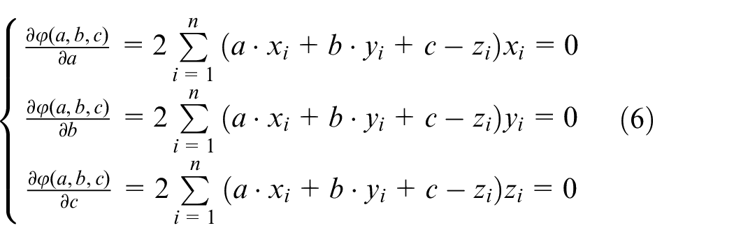
In the assembly process of parts, each matting surface will produce different degrees of small deformation, owing to manufacturing error and assembly load, which can be characterized by small displacement torsor. 40 Existing optimization models are based on the tolerance-cost model, which does not include the deformation factors of parts. Therefore, only by completing the mapping from small displacement torsor to tolerance. The small displacement torsor and tolerance can be better combined to realize the comprehensive design of assembly error, and finally meet the requirements of product precision and assembly function.
The small displacement torsor theory
The small displacement torsor (SDT) theory was proposed based on the metrology by Bourdet and Clement. 41 Its primary idea is to adopt the geometry of points to represent the ideal space surface, and then consider the change in space geometry within a certain tolerance range as the change behavior of some points. With the deepening of theoretical research, relevant scholars have described the mutual pose relationship between different surfaces based on the SDT theory, and the mutual relationship between different geometric elements was characterized via mathematical methods; subsequently, the change region of each geometry was obtained within the allowable range. 42
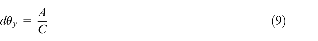
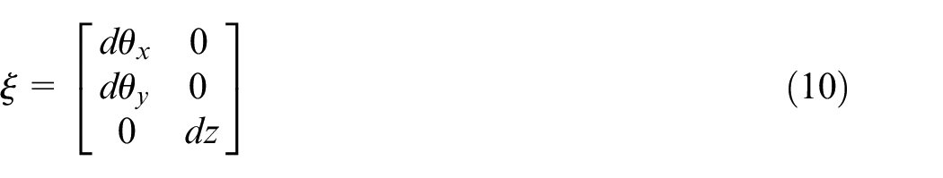
In space, the small deformation triggered by the motion of the object can be expressed by the small displacement torsor, which then forms the geometric feature change matrix represented by the spinor parameter. In the assembly process of product, the small deformation of each mating surface can be effectively expressed by the translation vector d =[dx dy dz]
T
and rotation vector θ
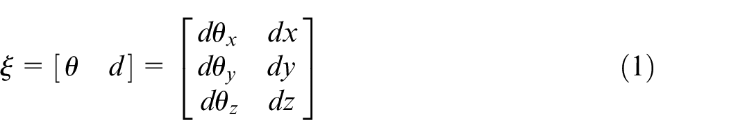
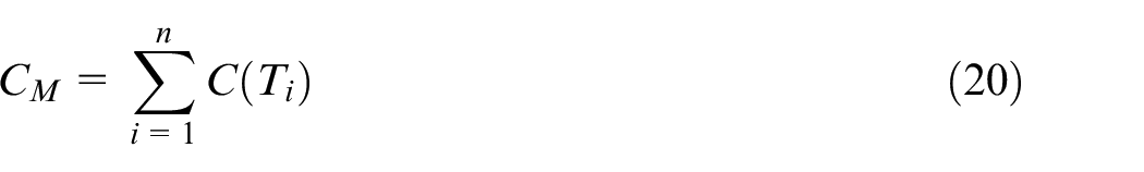
where dθx, dθy, and dθz represent the rotation of the matching features along the three x, y, and z coordinate directions, respectively. In addition, dx, dy, dz represent the translation of the matching features along the x, y, and z coordinate directions, respectively.
Acquisition of fitting deformation surface and pose spinor parameters
The effective fitting of mating deformation surface is premised to obtain small displacement torsor parameters. 43 In this study, the actual assembly is analyzed by the finite element method to obtain the deformation information and point cloud data of each node of the mating surface, and then the corresponding fitting deformation surface is obtained via the fitting operation algorithm. Finally, the pose spinor parameters of the geometric features are obtained by fitting the relationship between the deformation surface and the datum plane.
Acquisition of fitting deformation surface
According to the GPS, different geometric features correspond to different fitting operation algorithms. For the plane geometric features, this study primarily adopts the least square fitting algorithm,
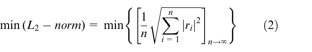
where i, n, and ri represent a series of discrete points in space, number of points constituting the actual elements, and difference between the ideal and actual elements, respectively.
It is assumed that the deformation plane under load is expressed as follows:

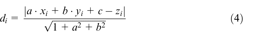
It is assumed that there are any deformation points (xi, yi, zi) in the space, i∈(1, 2, 3…, n). Hence, the distance between the deformation point and the plane is defined as:
According to the least square fitting method, the sum of squares of the differences between the ideal plane and actual deformation elements is expressed as follows:
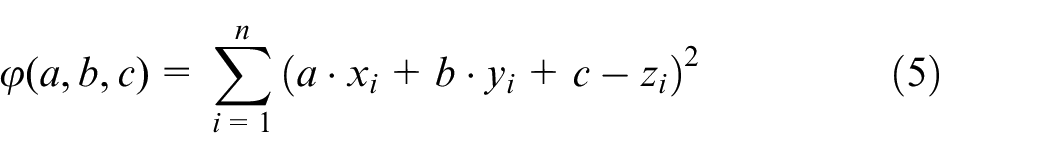
Equation (5) is processed by the least square method, and the following relation expression is obtained:
The equation (6) is expressed in a matrix form:
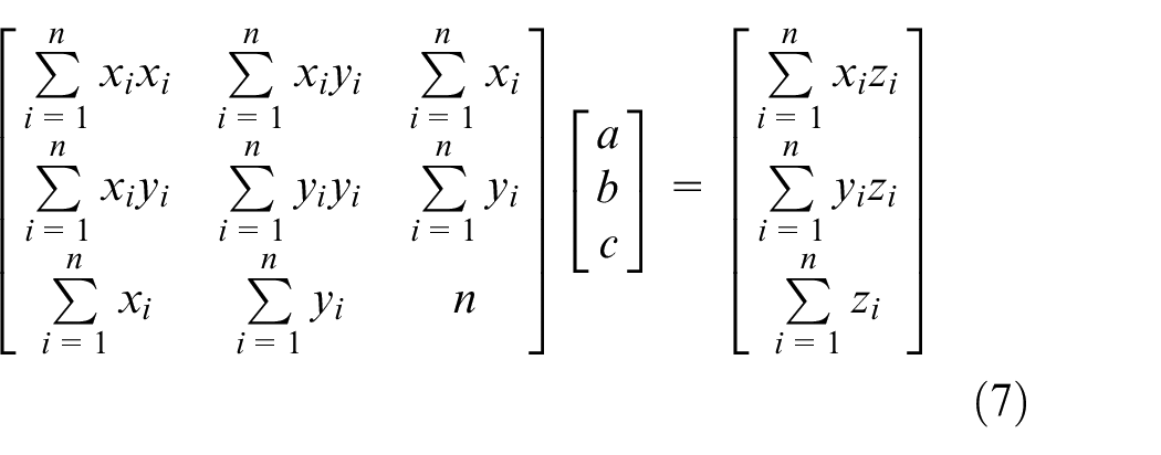
By solving equation (7), the unknown parameters (a, b, c) characterizing the plane equation are obtained, which are brought into the plane equation, then the fitting deformation plane of the part is obtained.
Solution of pose spinor parameters
On the basis of obtaining the fitting deformation surface, the relative rotation angle between the fitting deformation surface and the datum plane is adopted as the attitude spinor parameter, and the relative distance between the center point of the fitting deformation surface and the datum plane is taken as the position spinor parameter. Figure 1 illustrates the method for obtaining the pose rotation parameters.
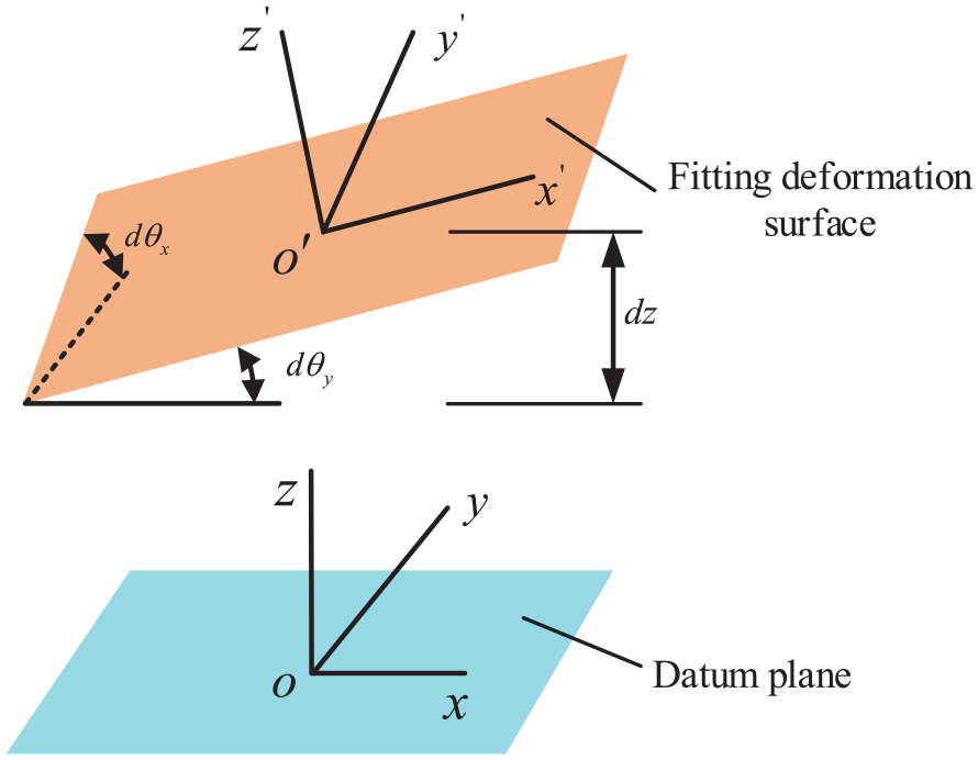
Solution of pose torsor parameters.
According to Figure 1, the fitting deformation surface is equivalent to rotating a certain angles (
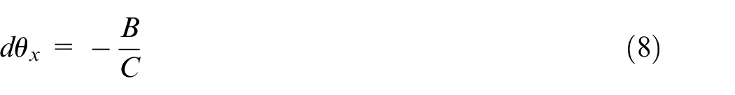
Hence, the pose screw of plane geometric features, including manufacturing error and assembly deformation, can be obtained by substituting them into equation (1),
Mapping from small displacement torsor to tolerance
This study mainly analyzes the mapping process, from small displacement torsor to tolerance, for the circular mating surface of a revolving body structure, in which the revolving body’s height is L and the circle radius is r, as depicted in Figure 2.
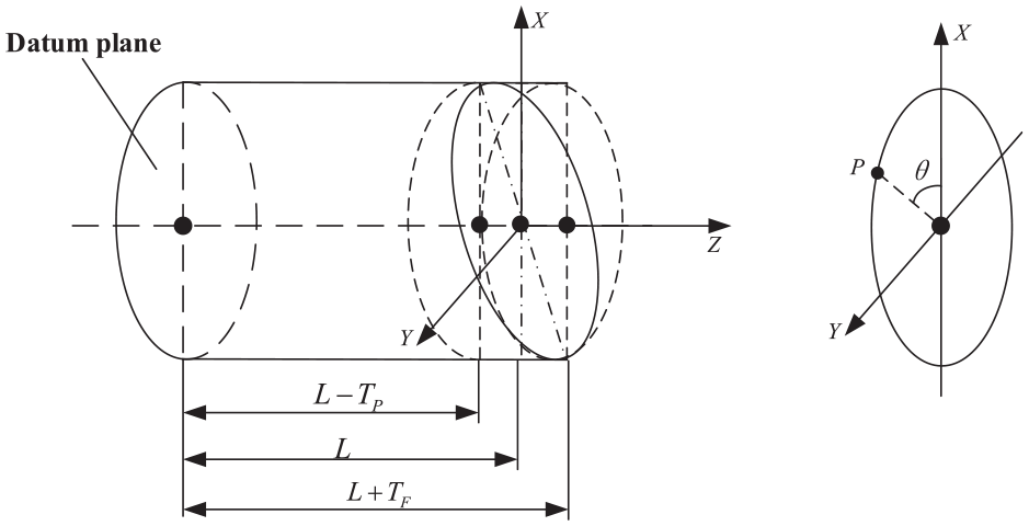
Schematic diagram of dimensional tolerance for circular plane.
According to Figure 2, for the mating end face of the circular feature, there is an extreme point on the circumference. Assuming that there is a point P on the circumference, and the angle between that point and the positive direction of the X axis is θ, then the coordinates of any point P on the circumference can be expressed as (rcosθ, rsinθ, 0). Therefore, the pose torsors generated by the point P on the circumference can be expressed by equation (11):
where
It can be observed from Figure 1 that the left and right boundaries of the tolerance region of circular surface dimensions are two different planes,
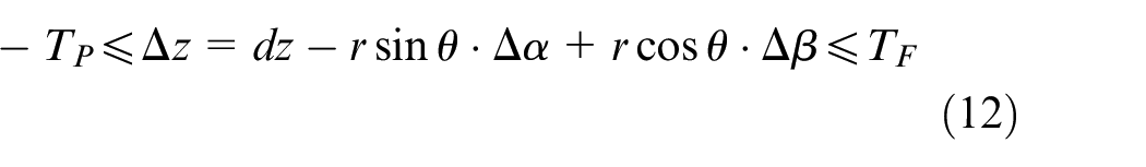
It can be deduced from equation (12) that θ is a free parameter; hence, the extremum on the circumference can be obtained by deriving
For the maximum value
For the minimum value
The tolerance T of the small displacement torsor mapping is obtained via the extremum analysis method,

Its boundary is expressed as:

For the upper boundary of the surface:

For the lower boundary of the surface:

Construction of error optimization model considering manufacturing error and assembly deformation of parts
The conventional tolerance optimization model is primarily based on the tolerance range given in the design stage; however, there are manufacturing errors and assembly deformation in the manufacturing and assembly processes of parts. Therefore, on the basis of meeting the requirements of design tolerance, an assembly error optimization model considering manufacturing errors and assembly deformation of parts is established, which will help to analyze the accuracy characteristics, and then achieve the objective of low cost and high accuracy.
In the machining process, the processing equipment, resource occupation, and manpower increase with the improvement in machining accuracy. In addition, the relationship between manufacturing error and cost is approximately in an inverse proportion. Presently, the exponential, power exponential, negative square, polynomial, and composite models are the main tolerance-cost models adopted by designers.
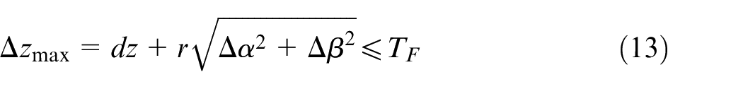
According to the related literature, 44 for the plane geometric features, the relationship model between tolerance and cost is expressed as:
In the assembly dimension chain of parts, if the processing cost of parts under the manufacturing error
Equation (19) is a cost model commonly used by enterprises and designers, which is obtained according to the relationship between different machining accuracy and cost obtained by enterprises in the manufacturing process.
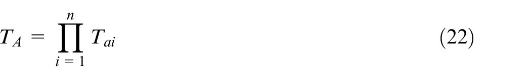
The total cost

Presently, the research on the tolerance-cost model primarily focuses on the machining error of parts, and there is no deformation-cost model reflecting the assembly process. The assembly accuracy is obtained by accumulating the manufacturing and assembly errors of the matching parts. Suppose that
The small displacement torsor
To calculate the machining and assembly costs of parts, it is necessary to transform
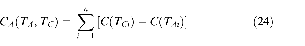
According to the above analysis, if the error is reduced from
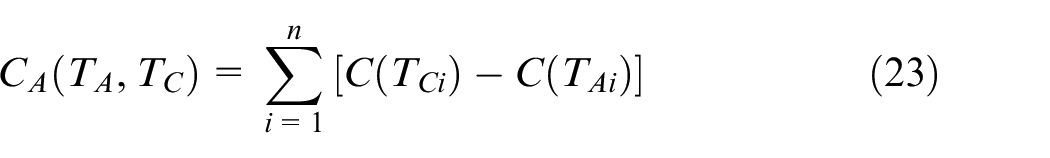
Based on the costs,
High performance and low cost must be considered in the product design and manufacturing processes. Mechanical products primarily focus on the total cost of parts in processing and assembly. Therefore, the assembly error optimization model is established with the constraint of the assembly function and economic machining accuracy, as well as the objective of reducing the total cost, which can provide an effective reference for product design with low cost and high accuracy requirements.
According to the above analysis, the error optimization model of assembly is expressed as:
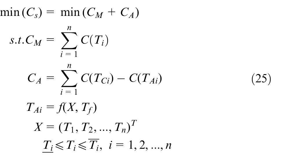
where
Case analysis
Example introduction
In this study, the high-pressure rotor of an aeroengine is taken as the analysis object, which is assembled by the key parts, such as the front shaft, multi stage disk, turbine disk, and rear shaft through different mating surfaces, as illustrated in Figure 3. This study primarily optimizes the manufacturing error of the mating surface for the high-pressure compressor rotor system, which lays the foundation for achieving high assembly accuracy under the low manufacturing cost.
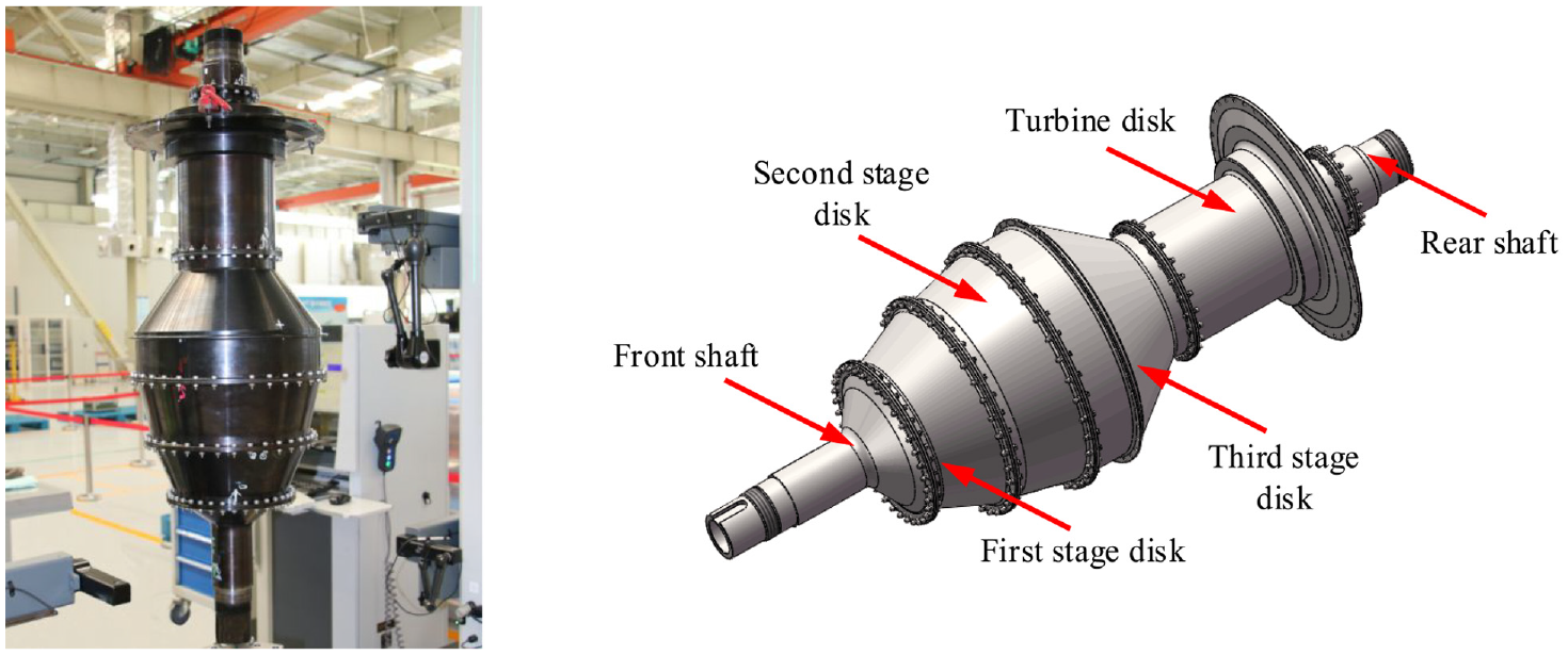
High-pressure rotor of an aeroengine.
As illustrated in Figure 3, the rotor system of a high-pressure compressor is assembled by multiple parts. In addition to manufacturing errors in each mating end face, certain deformations exist owing to assembly load, which ultimately affects the assembly performance of the entire machine. Therefore, the construction of the error optimization model, including manufacturing error and assembly deformation, to achieve error optimization has an important reference value for improving the parts design and system performance.
Manufacturing error measurement of mating surface for rotor system
According to the engineering application, in the assembly process of high pressure compressor rotor systems, the runout error of the mating end face of each part is a major factor that affect the assembly accuracy and performance. In this study, the IMAP4 integrated measurement and assembly platform is used to measure the end jumps at each mating surface for the rotor system. The IMAP4 integrated measurement and assembly platform is illustrated in Figure 4.
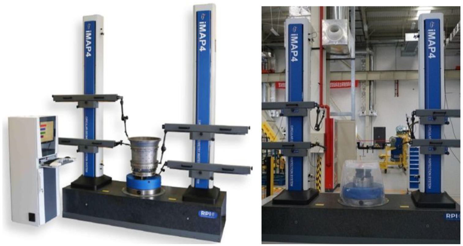
Integrated measurement and assembly platform.
The IMAP4 platform is used to measure the end jumps on the mating surfaces of the rotor system, from the front shaft to the rear shaft. In the test process, the lower end face of the parts is taken as the benchmark, and the manufacturing error of the upper end face is measured by leveling the turntable. The test method is illustrated in Figure 5.
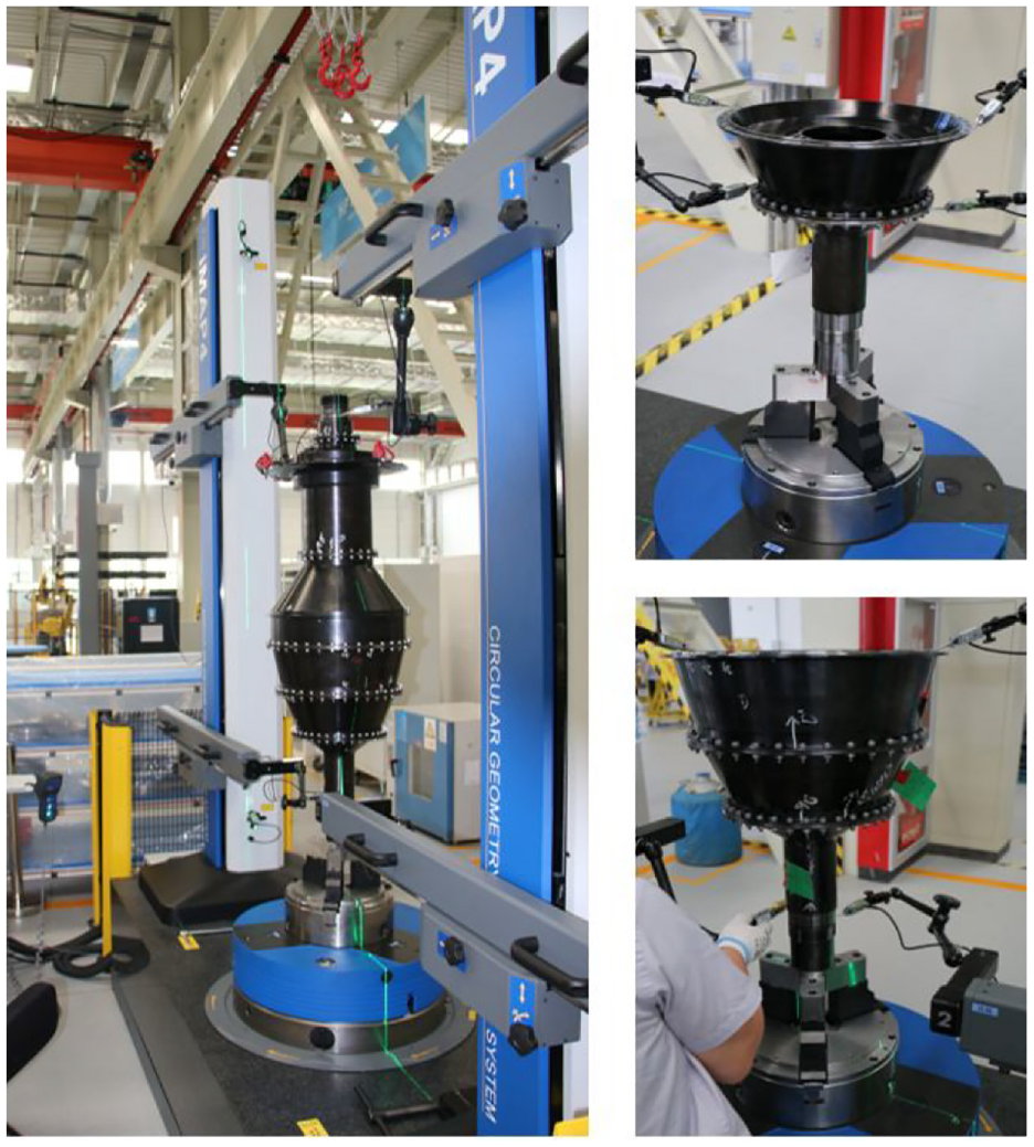
Measurement of end jump for high pressure compressor rotor (HPCR).
To reflect the consistency of data and the effectiveness of the test method, two groups of data were measured for each mating surface, according to different measuring diameters D. The test data of each end face are presented in Figure 6.
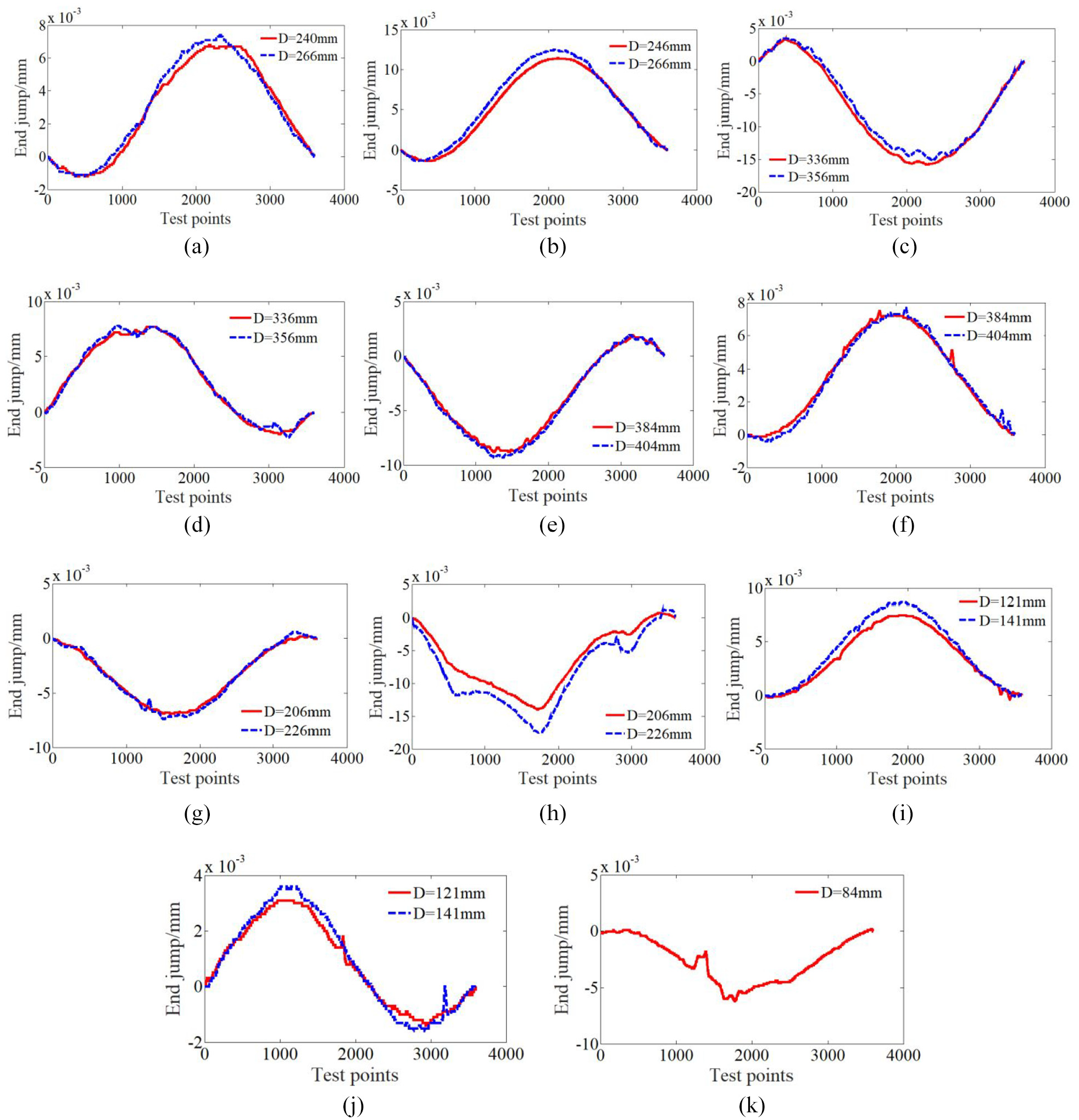
End jump of different mating surfaces for high pressure compressor rotor: (a) upper end face of front shaft, (b) lower end face of first stage disk, (c) upper end face of first stage disk, (d) lower end face of second stage disk, (e) upper end face of second stage disk, (f) lower end face of third stage disk, (g) upper end face of third stage disk, (h) lower end face of turbine disk, (i) upper end face of turbine disk, (j) lower end face of rear shaft, and (k) upper end face of rear shaft.
Acquisition of pose torsor of mating surface including manufacturing error and deformation of parts
According to the above analysis, the current error optimization model primarily considers the manufacturing error of parts; however, it does not pay the same level of attention to the deformation of parts under load, which causes the error optimization results to differ from the actual results. Therefore, the key to error optimization is to effectively obtain the true pose torsor of each mating surface, and then construct the error optimization model, considering the manufacturing error and deformation, using the mapping relationship between torsor parameters and tolerances.
This part considers the high pressure compressor rotor as the object, adopts the numerical analysis method to perform the mechanical analysis of the rotor system, and then extracts the node deformation information of each mating surface, from the front to the rear shaft. Accordingly, the least square fitting algorithm is used to obtain the fitting deformation surface and pose torsor parameters of each end face, which provides the data basis for constructing the error optimization model.
Owing to the space limitation, this section only provides the process for obtaining the pose torsor of the mating surface between the front shaft and the primary disk. For the assembly of the front shaft and the first stage disk, the upper end face of the front axle and the lower end face of the first stage disk are the mating surfaces. The fitting deformation surface of the mating end face is obtained via the numerical analysis method and the least square fitting algorithm, as presented in Figure 7.
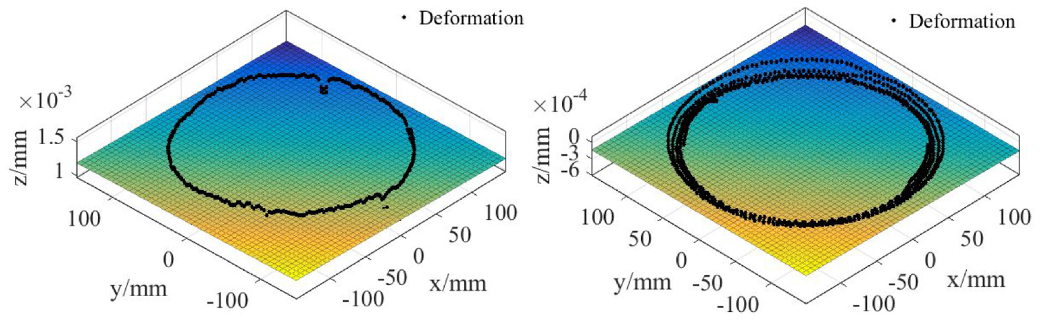
Fitting deformation surface of the mating surface for front shaft and first stage disk: (a) upper end face of the front shaft and (b) lower end face of the first stage disk.
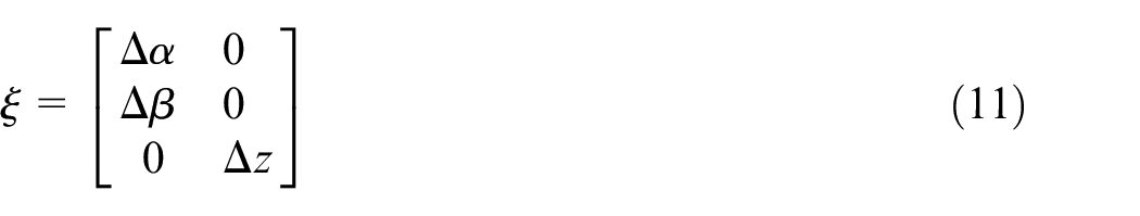
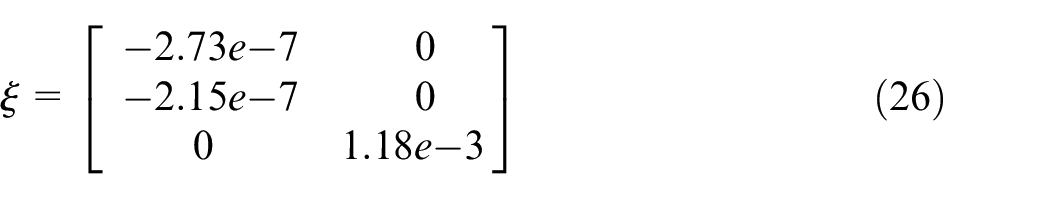
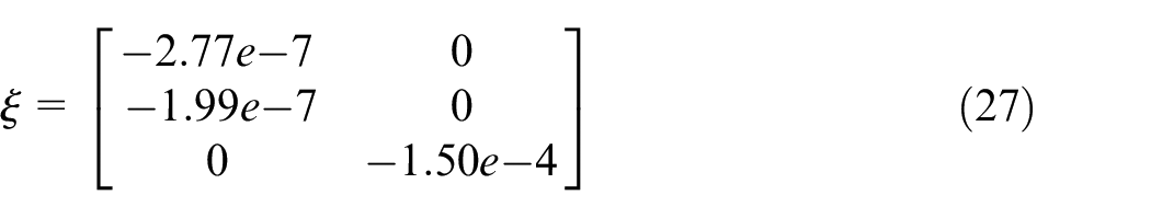
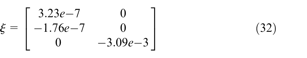
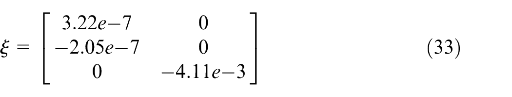
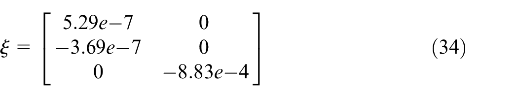
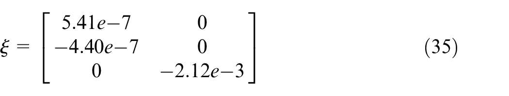
On the basis of obtaining the fitting deformation surface of each mating surface, the pose spins of the upper end face for the front shaft and the lower end face for the primary disk are obtained via the position relationship between the fitting surface and the reference plane, respectively, as expressed in equations (26) and (27).
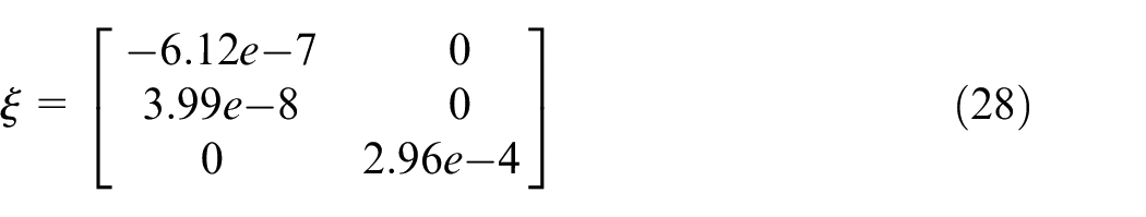
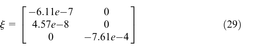
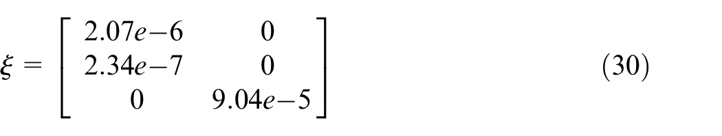
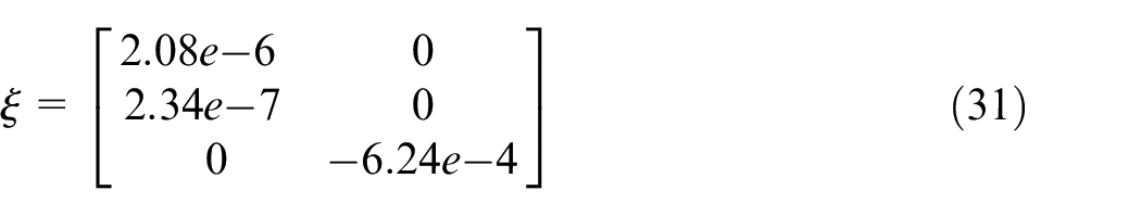
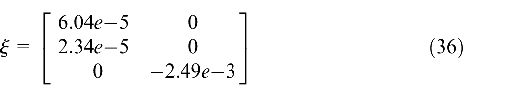
The pose spins of the upper end face of the first stage disk, the lower/upper end face of the second stage disk, the lower/upper end face of the third stage disk, the lower/upper end face of the turbine disk, and the lower/upper end face of the rear shaft can be obtained by adopting the same method, as expressed in equations (28)–(36).
Error optimization considering manufacturing error and assembly deformation of parts
This section takes the high-pressure rotor system of an aero-engine as the object, primarily studies the error optimization design method of the assembly with assembly accuracy as the constraint condition, and considers the total costs of the manufacturing and assembly processes as the objective, such that the unnecessary cost loss can be avoided on the premise of ensuring the assembly accuracy of products.
The cost of the high-pressure rotor system primarily comprises parts processing and assembly costs. Because the high-pressure rotor is a precision component with high-speed rotation, on the premise of satisfying the design dimension requirements of parts, it is necessary to ensure the manufacturing error of parts and the deformation triggered by load during assembly.
It is assumed that the manufacturing error of the mating surfaces for the front shaft, multi-stage disk, turbine disk, and rear shaft of the high-pressure rotor system is
where i represents different mating faces (there are 11 mating faces from the front shaft to the rear shaft);
It can be observed from the second chapter that the pose screw parameters of the upper face of the front shaft, lower/upper face of the first stage disk, lower/upper face of the second stage disk, lower/upper face of the third stage disk, lower/upper face of the turbine disk, and lower/upper face of the rear shaft under load are obtained from equations (26) to (36).
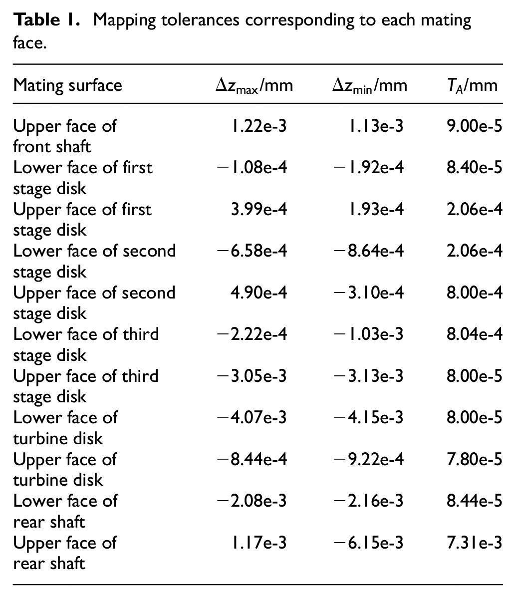
On the basis of obtaining the pose screw parameters of each mating surface, the maximum and minimum values of each pose spinor parameter can be obtained according to equations (13) and (14), and then the tolerance
Mapping tolerances corresponding to each mating face.
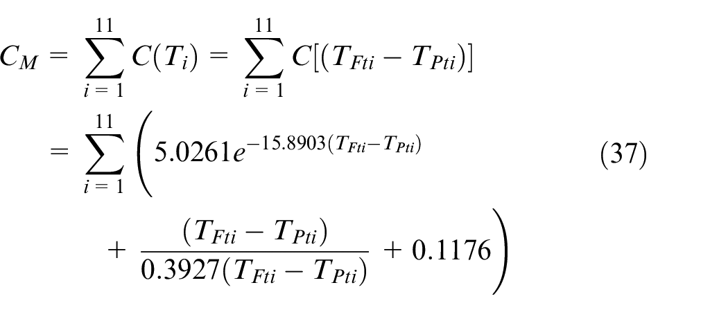
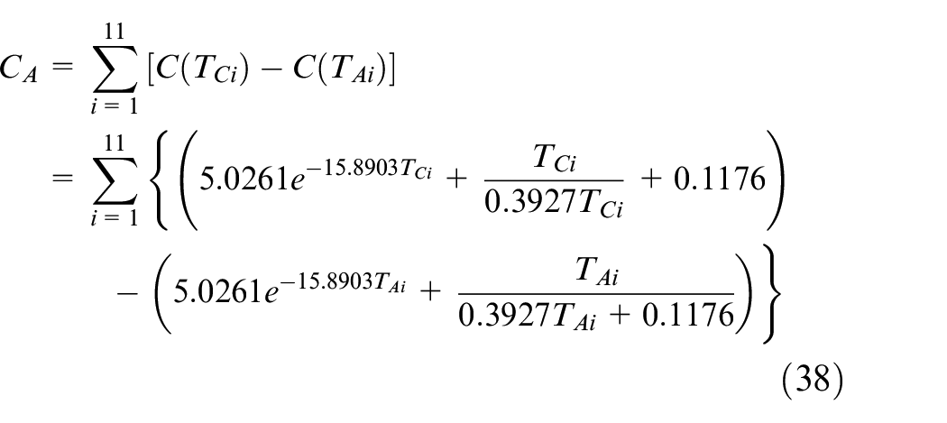
According to the mapping relationship between the small displacement torsor and tolerance, the assembly process cost of the rotor system can be obtained by equation (38),
Based on the above analysis, the error optimization model of the entire assembly process for the high pressure compressor rotor system is constructed, as expressed in equation (39):
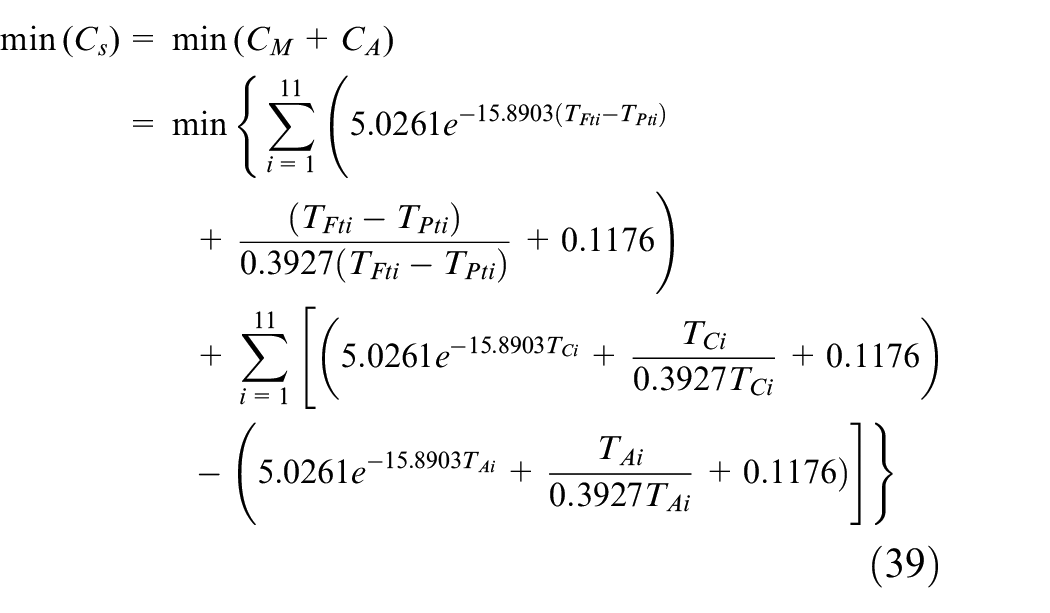
The constraint conditions are defined as follows:
where
To verify the practicability and effectiveness of the optimization model, the manufacturing error obtained from the test is introduced into the optimization model. Because the manufacturing error of parts is controllable, this section only optimizes the manufacturing error, and the obtained results are presented in Table 2.
Comparison of optimization results.
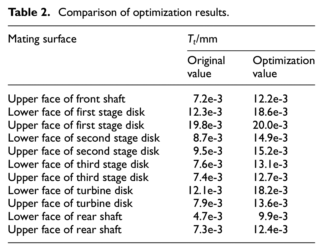
It can be observed from Table 2 that under the premise of meeting the requirements of processing accuracy and assembly function of parts, the manufacturing error of each mating surface after optimization changes from small to large, and the expansion of the error range implies a reduction in the processing difficulty of parts, which also indicates an improvement in the parts processing efficiency from another perspective. Simultaneously, the relative manufacturing cost after optimization is reduced by 6.79%, which satisfies the economic requirements to a certain extent.
Conclusion
A major objective for improving the competitive advantage of products is to achieve the high assembly accuracy and performance of mechanical systems based on low manufacturing accuracy and cost of parts. This study primary adopted the mathematical method to obtain the pose screw parameters of the mating surface, which include the manufacturing error and deformation of the parts, and then developed an assembly error optimization model by mapping the small displacement screw to the tolerance. Furthermore, this study realized the manufacturing error optimization design of the mating face. The conclusions drawn from this study are presented as follows:
The least square fitting algorithm is adopted to obtain the pose screw parameters of the matching surface, which include the manufacturing error and deformation of the parts. The mapping between the small displacement screw and the tolerance domain is completed via the extreme value analysis method; accordingly, the combination of the small displacement screw and the tolerance is realized;
Based on the mapping relationship between small displacement screw and tolerance, an assembly error optimization model, considering the manufacturing error and deformation factors, is established based on the conventional tolerance-cost model, which is closer to the actual assembly process.
Taking the assembly accuracy requirement as the constraint condition, and the total costs of the manufacturing and assembly processes as the objective, the manufacturing error optimization of each mating surface of the high pressure rotor system is realized. The results obtained indicate that the manufacturing error range of each mating surface after optimization changes from small to large, which indicates a reduction in the difficulty of parts processing, and an improvement in the efficiency of parts processing. Simultaneously, the relative manufacturing cost after optimization is reduced by 6.79%, which satisfies the economic requirements to a certain extent.
An error optimization method, considering the manufacturing error and deformation of parts, are proposed in this study. Although we have conducted studies on the error optimization, this method is mainly suitable for cylindrical parts. In future research, we will further expand the application scope of this method, such as the assembly process of rectangular parts and ring parts, to develop a more general error optimization model and method, which then provides the necessary design basis for realizing a high assembly accuracy of mechanical systems, under the condition of low cost and manufacturing accuracy from the design perspective.
Footnotes
Declaration of conflicting interests
The author(s) declared no potential conflicts of interest with respect to the research, authorship, and/or publication of this article.
Funding
The author(s) disclosed receipt of the following financial support for the research, authorship, and/or publication of this article: This work was supported by the National Natural Science Foundation of China (No. 51875081, 52005081); Major Special Basic Research Projects (2017-VII-0010).