
Abstract
Face gear dynamics is addressed by many scholars, and vibration suppression of face gear drives is always one of study focuses of face gear dynamics. However, vibration active control solutions of face gear drives are still yet to be constructed. Thus, in the study, a web active control solution of face gear drives, in which face gear web structures are employed to achieve static transmission error active control, is proposed, and a web circumference deformation calculation solution is constructed, as well as a four-degrees of freedom dynamic model of face gear drives is established, and two version control methods of static transmission error are presented. Furthermore, an example case of face gear drives associated with the proposed web active control solution is simulated. The results indicate that effects of the proposed web active control solution on dynamic behaviors of face gear drives are significant, and the fidelity of the proposed web active control solution could be accepted. These contributions would benefit to improve face gear vibrations and engineering applications of face gear drives.
Keywords
Introduction
A face gear drive is a kind of intersection gear drives and is recommended to be employed in first-stage gear drives of helicopter main gear boxes by Litvin et al.;1–6 according to their study achievements, namely, insensitive characteristics of manufacture and alignment errors of face gear drives versus spiral bevel gear drives. Therefore, face gear dynamics is focused by many scholars, due to the operating conditions of first-stage gear drives in helicopter main gear boxes. There are many lectures discussing the dynamic behaviors of face gear drives in the past few years. Hu et al. 7 assessed the effects of mesh stiffness on dynamic responses of face gear drives. Wang et al. 8 discussed the linear face gear dynamic behaviors. Jin et al. 9 established a non-linear dynamic model of face gear drives. Yang et al.10,11 evaluated the vibration and bifurcation characteristics of face gear drives. Li et al. 12 investigated the influences of frictions on dynamic behaviors of face gear drives. Zhang et al. 13 studied the nature frequencies of split face gear drive systems. Based on face gear dynamic behavior investigations, vibration suppression of face gear drives would be addressed by researchers gradually. Gear vibration suppression solutions could be divided into two catalogs: one is a passive solution and the other is an active solution. Active solutions, namely, vibration active control, are better than passive solutions, due to operating condition adaptabilities. Li et al.14–18 employed additional torque generated by piezoelectric actuators on wheels and additional bending displacement limit devices on shafts to develop vibration active control of gear drives, respectively. Li et al. 19 also used similar solutions to discuss the effects of vibration active control on dynamic behaviors of spur gear drives. Mohamed et al. 20 employed an adaptive neuro-fuzzy inference system controller to suppress a low-speed planetary gearbox rotational vibration acceleration levels actively. According to limited published issues, active control solutions could be divided into two types: one is to reduce vibration sources and the other is to suppress vibrations on transfer paths. Solutions of vibration suppressions on sources are better than those on transfer paths, due to ultimate source reductions. However, the existed vibration active control solutions for gear vibration sources are focused on additional torques, not on gear wheel body structures, which could be employed to suppress static transmission errors (STE). Thus, in the study, a vibration active control solution, based on web circumferential deformation changes, of face gear drives is proposed, a web circumferential deformation calculation solution is constructed, a four degrees of freedom (DOF) face gear dynamic model is formulated, and two version active control methods of STE are presented. Furthermore, dynamic behaviors of an example case of face gear drives associated with the proposed web active control solution are simulated. The results indicate that STE of face gear drives could be controlled easily by more web layers and less actuators per layer, and suppressions of dynamic mesh forces and dynamic behaviors of face gear drives could be achieved by the presented first STE active control method, obviously. Meanwhile, changes of dynamic behaviors and spectrum distribution forms of dynamic mesh forces of face gear drives could be accomplished by the proposed second STE active control method. According to the limited results in this issue, the fidelity of the proposed web active control solution of face gear drives could be accepted. These contributions would be helpful to reduce vibrations of face gear drives and improve engineering applications of face gear drives in the future.
Construction web active control solutions
Web structures associated with active control
Based on a viewpoint, namely, the rotation of the wheel body being an important factor on flexibilities of gear teeth, 21 namely, mesh stiffness and STE being affected by gear wheel body flexibility sharply, a vibration active control solution associated with face gear web structures, as shown in Figure 1, is proposed.
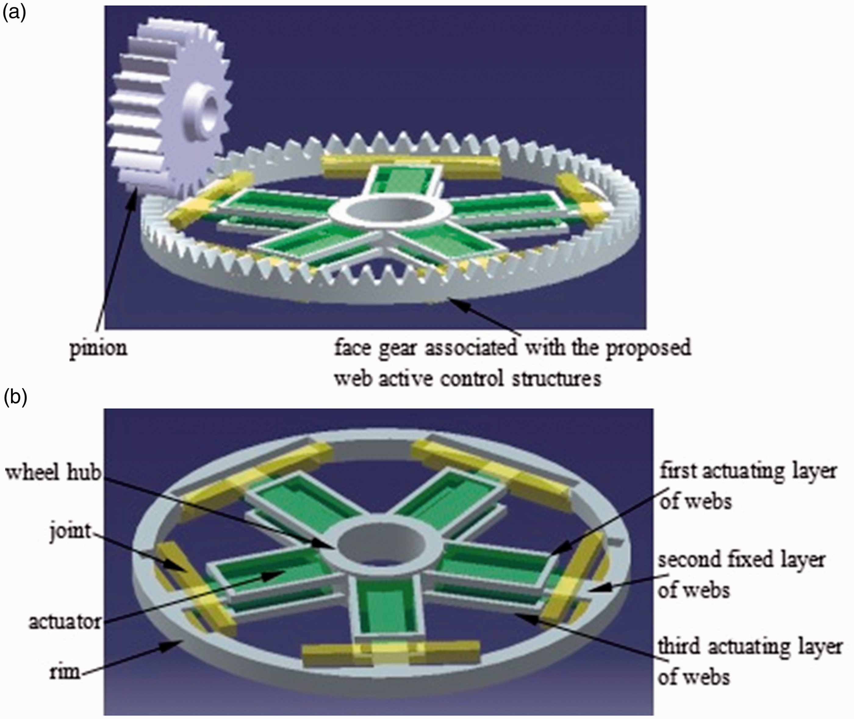
The proposed vibration active control solution. (a) A face gear drive associated with web active control structures; (b) the local view of web active control structures.
As illustrated in Figure 1, a face gear web could be divided into two version layers: one is an actuating layer, such as the first and the third layers, namely, the layer associated with actuators and not contacted with rims at initial states, and the other is a fixed layer, such as the second layer, meaning, the layer without actuators and contacted with rims at initial states.
Wheel body rotation deformation calculation solutions
According to Zhu and E
21
and Liang et al.,
22
traditional rotation deformations of wheel bodies of face gear drives, namely, web circumferential deformations of face gear drives without the proposed web active control structures, could be written in
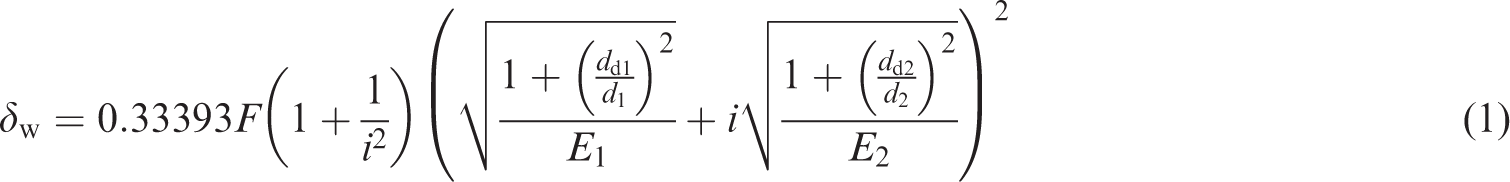
Due to extra web circumferential deformations caused by the proposed face gear web structure associated active control, the calculation solution of rotation deformations of wheel bodies of face gear drives associated with the web active control structure should be modified via the adjustment of symbol dd2. In order to assess adjustments of symbol dd2, a sketch of web structures associated with active control is given in Figure 2.
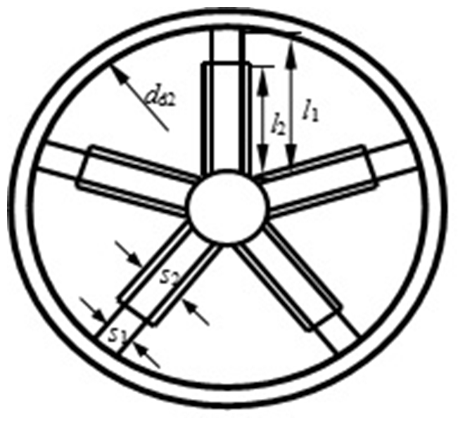
A sketch of the proposed web active control structure.
As shown in Figures 1 and 2, according to material mathematics, rim circumferential deformations could be expressed as
23

According to cantilever beam deflection calculation solutions in material mechanics, extra web circumferential deformations of fixed layers and actuating layers could be derived by


According to relationships between web layers, as shown in Figure 3, the circumferential deformation caused by web layers can be deduced as

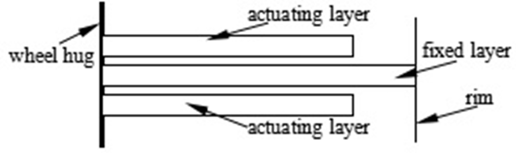
Relationships between web layers.
As given in Figures 2 and 3, symbol ϕv, namely, rotation deformations of wheel bodies of face gear drives associated with the proposed web active control solution, could be equal to

Thus, according to equations (2) and (6), a symbol dv, namely, an equivalent web internal diameter, in which extra web circumferential deformations caused by the proposed face gear web structure associated active control are considered, could be deduced as
Introducing equation (7) into equation (1) to alter symbol dd2, the rotation deformation of wheel bodies of face gear drives associated with the proposed web active control solution could be determined.
Dynamic model
In order to assess the effects of web active control on torsion-bending coupled dynamic behaviors of face gear drives, lumped-mass method was employed and under the condition of neglected frictions, a four DOFs, namely, two torsion DOFs and two bending DOFs coupled, dynamic model of face gear drives, as shown in Figure 4, are established, and the proposed web active control is introduced into the dynamic model by STE, which changes are caused by tooth deformations 24 and rotation deformations of wheel bodies of face gear drives associated with the proposed web active control solution.
A four DOF dynamic model of face gear drives.
As illustrated in Figure 4, θ is a torsion DOF, s is a bending DOF, T is a torsion, k is a bending stiffness, c is a bending damping, subscripts f and p express face gears and pinions, respectively, km is a mesh stiffness of face gear drives, cm is a mesh damping of face gear drives, γ is a shaft angle of face gear drives, and e is a STE, which could be defined as

Based on Figure 4, the mathematic equations of the dynamic model could be derived by

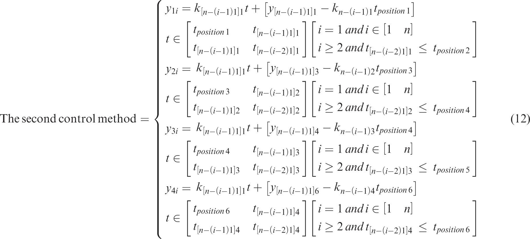
Two version control methods of STE
In order to accomplish STE control and according to STE forms, two version STE control methods are presented. One is STE key point control, and the seven key points include an engagement ponit, four single-double-tooth-mesh-alternating points, a pitch point, and a mesh-out point, and the STE control could be expressed as
Simulation and analysis
Impact analyses of the proposed active control solution on STE
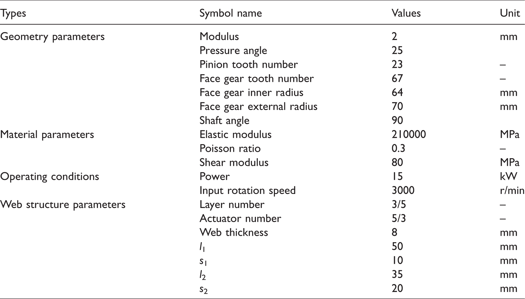
In order to assess the effects of the proposed web active control on dynamic behaviors of face gear drives, parameters of an example case of face gear drives associated with web active control structures are listed in Table 1.
Parameters of an example case of face gear drives.
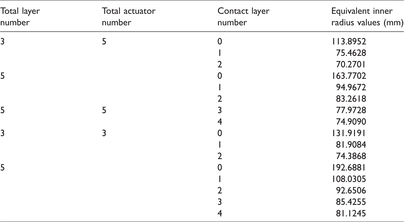
According to equation (7), the equivalent inner radius of the example case of face gear drives could be obtained, as listed in Table 2.
Equivalent inner radius of the example case of face gear drives.
Thus, according to equation (8) and the first control method, namely, STE key point control, when the total layer number is taken as 3 and the total actuator number is given as 5, the STEs of the example case with the different contact layer numbers are simulated as shown in Figure 5(a).
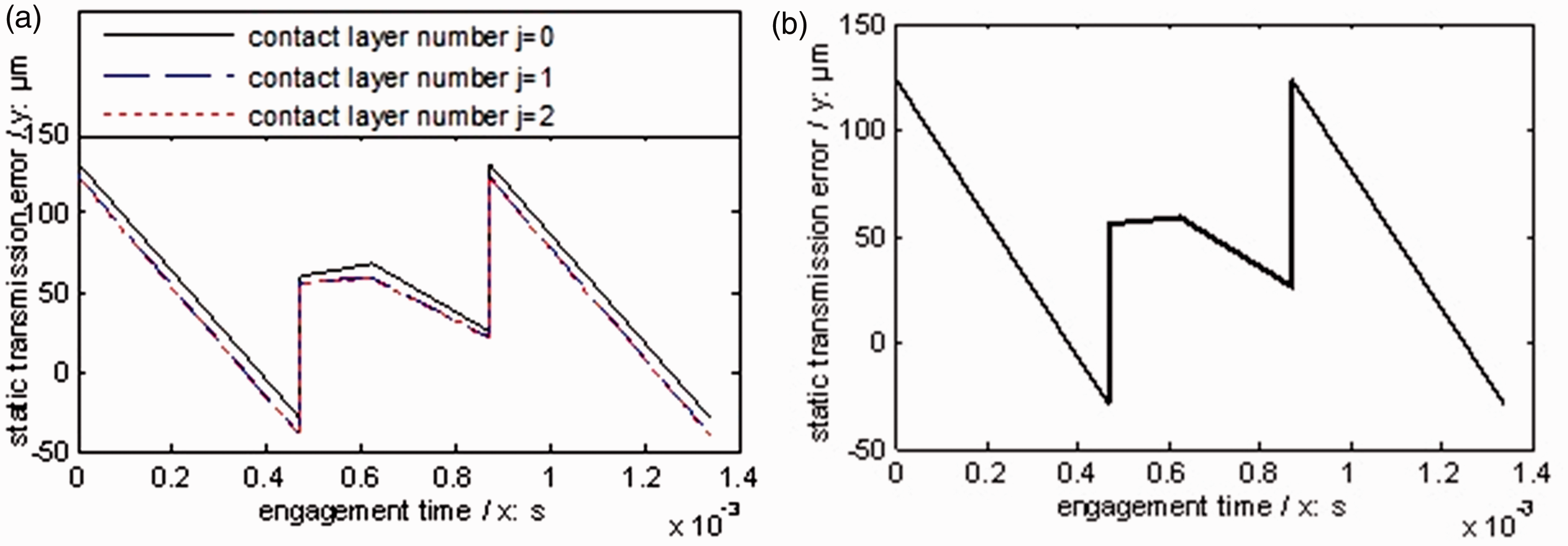
STE simulations of the example case with three layers and five actuators. (a) STEs with the different contact layer numbers; (b) STE with the first control method.
In Figure 5(a), STE key point amplitudes would be changed with the increase of contact layer numbers, and through controlling the contact layer numbers, a placid STE curve versus the STEs as given in Figure 5(a) could be gained, as shown in Figure 5(b).
According to STE simulation procession associated with the first active control method, as shown in Figure 5, the STEs after the control by the first version method and associated with the different total layer numbers and total actuator numbers and the STE without any active control are simulated, as shown in Figure 6.
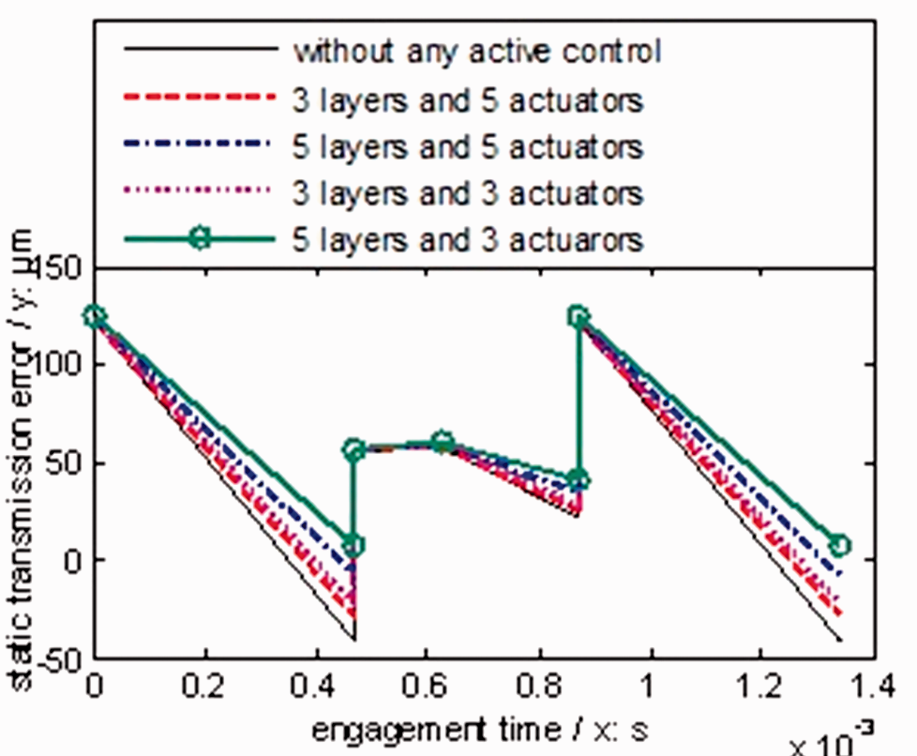
STE comparisons of the example case after the first control method.
In the case of Figure 6, after the first active control, the STE associated with the five contact layers and the three actuators per layer is most placid among the STE simulations, and the STE waves with the same contact layer numbers and the different actuator numbers per layer are less than those with the same actuator numbers per layer and the different contact layer numbers. Thus, the increase of total layer numbers of webs and the reduction of total actuator numbers per layer would make STE of face gear drives more gentle, and the STE associated with the proposed active control is more sensitive to total layer numbers of webs than actuator numbers per layer.
Influence analyses of the proposed active control solution on dynamic behaviors
According to Figure 6 and in order to assess the effects of the proposed web active control solution on dynamic behaviors of the example case of face gear drives better, the web structure associated with the five layers and three actuators of the example case of face gear drives is determined to be employed. The STE simulations associated with the web structure of the five layers and three actuators of the example case of face gear drives are given in Figure 7.
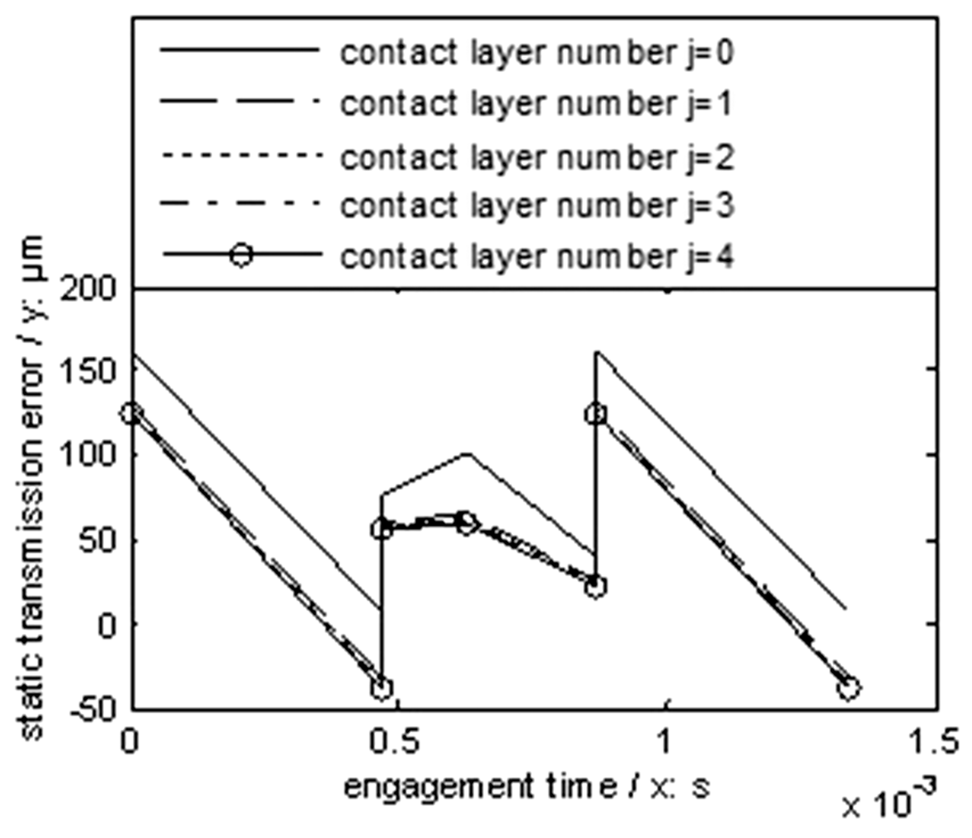
STE simulations of the example case with five layers and three actuators.
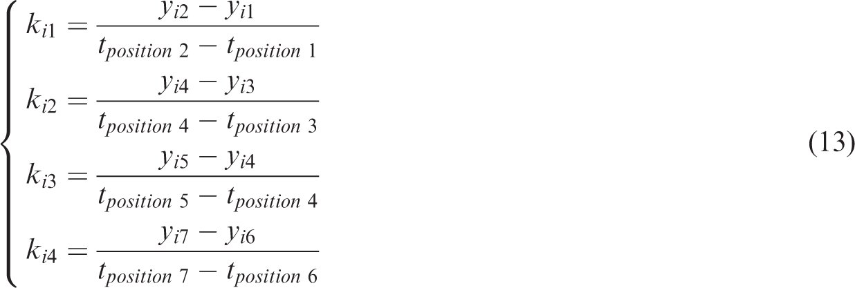
According to Figure 7, the STE difference between without contact layer and only one layer contacted is most obvious among the STE differences. Meanwhile, based on the presented two version STE control methods, namely, equations (12) and (13), the STEs of the example case after the control could be formulated, as shown in Figure 8.
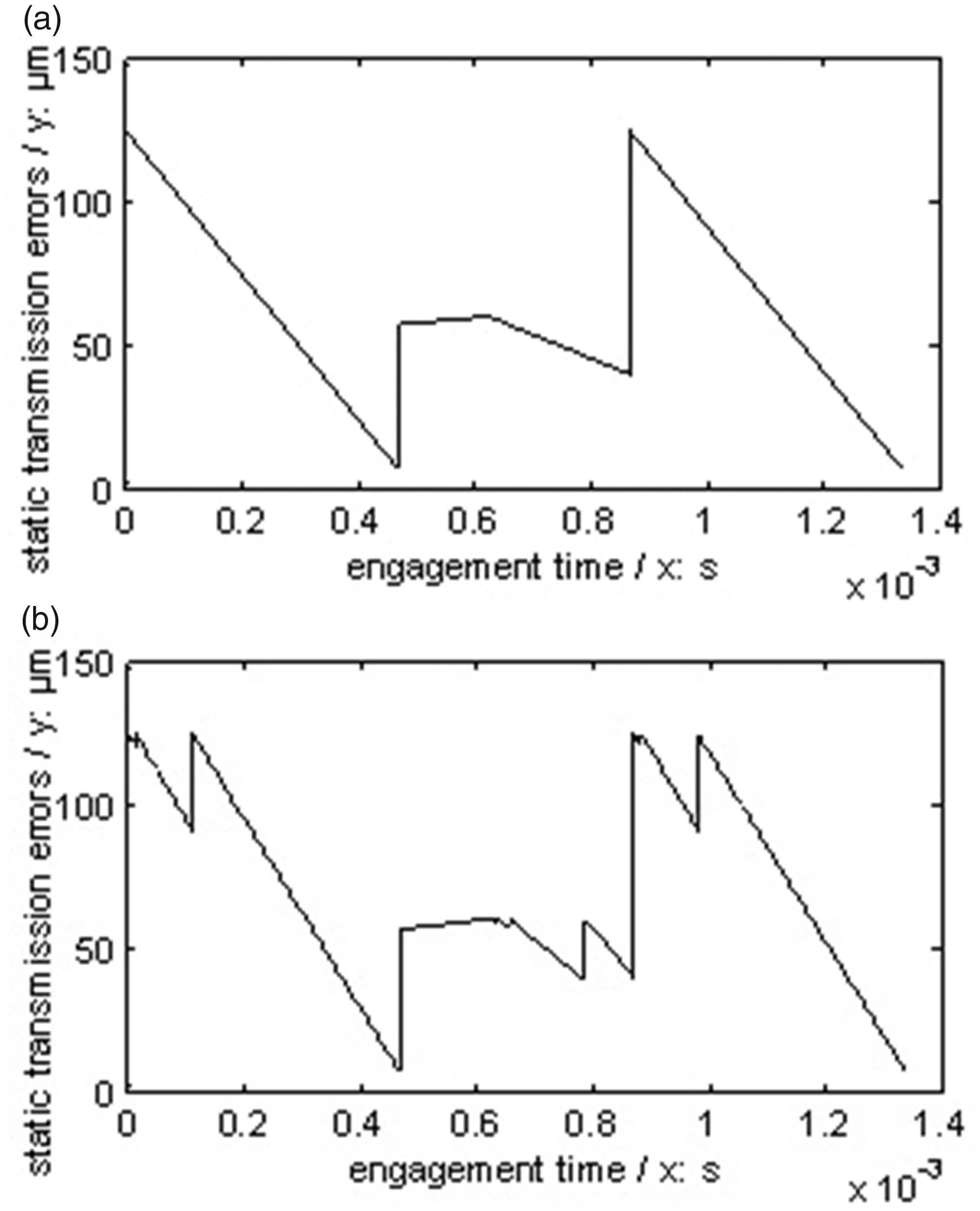
STE simulations after two version active control methods. (a) The first active control method and (b) the second active control method.
In Figure 8, the STE wave after the first active control method, namely, key point control method, is less than that after the second active control method, meaning, procession control method.
Introducing the two version STEs as shown in Figure 8, and the STE without any active control, as shown in Figure 6, into the dynamic model, namely, equation (9), the dynamic behaviors and the dynamic mesh forces of the example case are simulated, as shown in Figures 9 and 10, respectively.
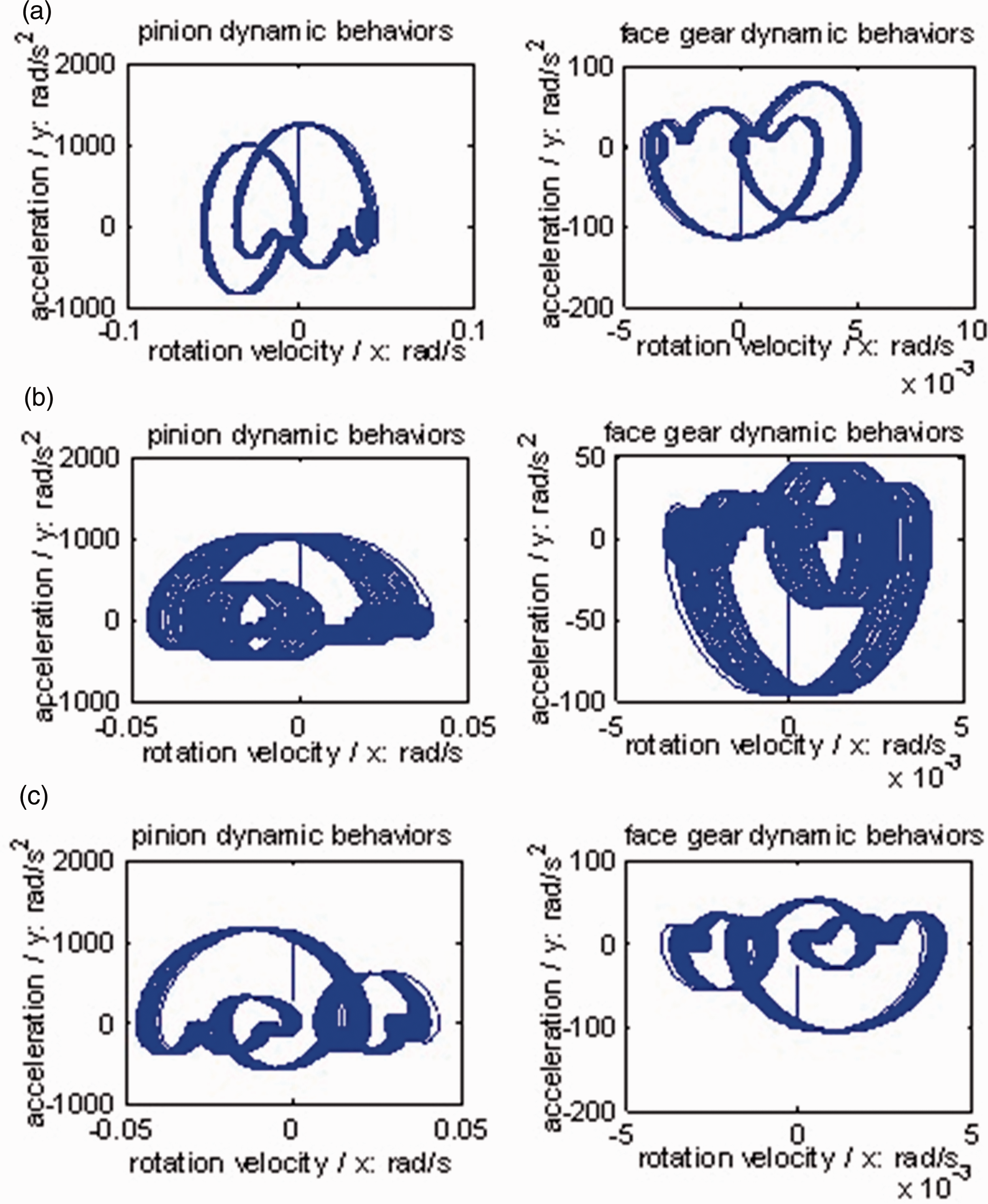
Dynamic behavior simulations of the example case. (a) Without any active control; (b) the first active control method; (c) the second active control method.
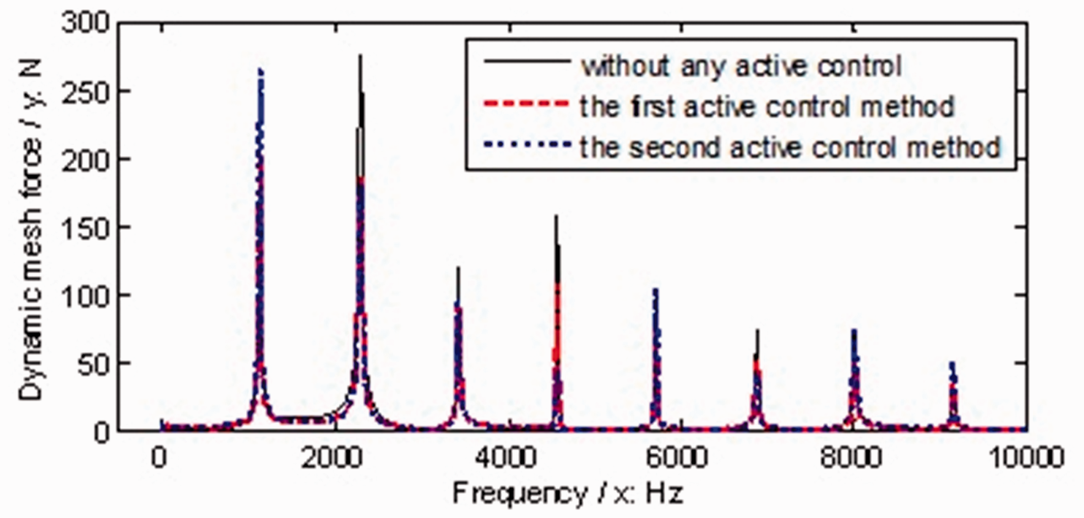
Dynamic mesh force simulations of the example case.
In Figure 9, when compared Figure 9(a) with Figure 9(b), the forms are similar, the amplitudes are reduced, and the escape quantities of the small rings are reduced. Meanwhile, when compared Figure 9(a) with Figure 9(c), the forms are not similar, due to the added rings in the big cycles, the amplitudes are still reduced, and the escape quantities of the small rings are increased.
As illustrated in Figure 10, after the first version active control, the spectral distribution form of the dynamic mesh force is not changed, and the amplitudes versus frequencies are almost reduced. While, after the second version active control, the spectral distribution form of the dynamic mesh force is changed.
A difference of average dynamic mesh forces of the example case of face gear drives between without any active control and after active control could be defined as

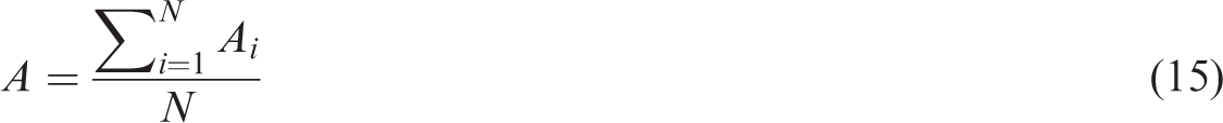
In the case of Figures 9 and 10, and according to equations (14) and (15), the vibration suppression effects of the proposed web active control solution on dynamic mesh forces of the example case of face gear drives could be expressed, as listed in Table 3.
Vibration suppression effects of the example case of face gear drives.
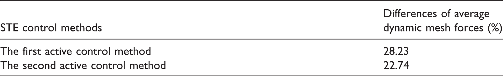
According to Table 3, the proposed web active control solution is significant, and the first STE active control method is better than the second for dynamic mesh force suppressions, namely, vibration suppression. Moreover, as shown in Figures 9 and 10, except vibration suppression effects, dynamic behaviors and spectrum distribution forms of dynamic mesh forces of the example case of face gear drives could be adjusted by the second STE active control method, which could be used to confuse spectral distribution detections.
Conclusions
In this study, three important works can be extracted as follows:
A web active control solution of face gear drives, only depended on face gear structures, is proposed, a web circumference deformation calculation solution of face gear drives is constructed, and two version STE active control methods are formulated. STE changes of face gear drives are more sensitive to layer numbers than actuator numbers per layer, and the increase of total layer numbers and the decrease of total actuator numbers per layer would let STE changes of face gear drives more gentle. Vibration suppression effects of face gear drives are significant by the proposed web active control solution, and the first STE active control method, namely, STE key point control, is better than the second, namely, STE procession control, for vibration suppression. However, except vibration suppression, the second STE active control method could adjust dynamic behaviors and dynamic mesh force spectrum distribution forms of face gear drives.
These contributions would be helpful to reduce vibrations of face gear drives and improve engineering applications of face gear drives in the future.
Footnotes
Acknowledgements
The authors are grateful for the financial support provided by the National Natural Science Foundation of China.
Declaration of conflicting interests
The author(s) declared no potential conflicts of interest with respect to the research, authorship, and/or publication of this article.
Funding
The author(s) disclosed receipt of the following financial support for the research, authorship, and/or publication of this article: The authors received financial support from the National Natural Science Foundation of China under no. 51775264 for the research, authorship, and/or publication of this article.