
Abstract
A survey of the literature related to theoretical and experimental studies on stick–slip vibration in oilwell drillstring is carried out in this study. It aims to explain key concepts and present the existing methods for studying this phenomenon. After briefly describing the stick–slip vibration related problems, theoretical models for such phenomenon are discussed including both coupled and uncoupled models. Discussion for experimental investigations including both laboratory and field tests are hereinafter addressed. This study aims to summarize the literature related to the stick–slip vibration, and help researchers in understanding and suppressing such phenomenon.
Introduction
The drillstring exhibits severe stick–slip vibration induced by the contact between the drill bit and the formation. 1 Stick–slip vibration of drillstring appears as periodic alternations of stick and slip phases. During the stick phase, the bit keeps stationary for a time interval and the torque on bit (TOB) increases to a value of breaking this state. During the slip phase, the bit releases all of a sudden and accelerates to an angular velocity several times as the velocity of rotary table.2,3 Stick–slip vibration not only reduces the tool life, but also increases the non-productive time that increases the development expense. In addition, this vibration may cause lateral and axial vibrations, causing equipment failure and the rate of penetration (ROP) reduction. 4
The investigation on stick–slip vibration in drillstring dated back to the publication of Belokobyl’skii and Prokopov 5 where the friction induced vibration was analyzed and the self-excited drillstirng vibration concept was introduced. Dareing 6 indicated the possibility of eliminating drillstring vibration by controlling the rotary speed and explored the self-excited vibration induced by motion of the bit. Dawson et al. 7 discussed the drillstring vibration as a stick–slip phenomenon.
The stick–slip phenomenon has undergone numerous outputs in the past decades; however, most of the publications are field observations and methods for mitigating this motion, including both passive and active methods. 8 Due to the variation of drilling conditions and drilling technologies advances, the stick–slip vibration plays an increasingly essential role. For instance, with the petroleum industry development, more and more deep and ultra-deep wells are considered for conduction.
This study reviewed the literatures on slick–slip vibrations for oilwell drillstring, thus providing reference for the engineers and scientists working on this area.
Stick–slip vibration with uncoupled models
The investigations reviewed in the following section are the mathematical methods for modeling stick–slip vibrations. The contributions are arranged under single degree of freedom (SDOF) lumped parameter models, multiple-DOF (MDOF) vibration models, and continuous system models.
SDOF Lumped pendulum vibration models
Halsey et al. 9 studied the stick–slip vibration of drillstring through treating the bottom-hole assembly (BHA) as a lumped flywheel. For given conditions, the SDOF model could not predict the formation of stick–slip motion. Kyllingstad and Halsey 10 revealed an increase in mean torque with increasing the rotary speed, however, the related explanation was not provided. The damping effect was not considered in the model. Lin and Wang 11 worked extensively on the lumped parameter model considering the damping effect.
To better understand the cause of stick–slip phenomenon, Brett 12 presented a model to show that torsional drillstring vibration can be initiated by variation of bit characteristics. The model regarded the drillstring as a lumped mass-spring system (Figure 1), and uses two coupled differential equations to describe the stick–slip motion. The results indicated that stick–slip vibration could be eliminated by controlling rotary table torque instead of rotary table velocity, which was not verified with field-test.
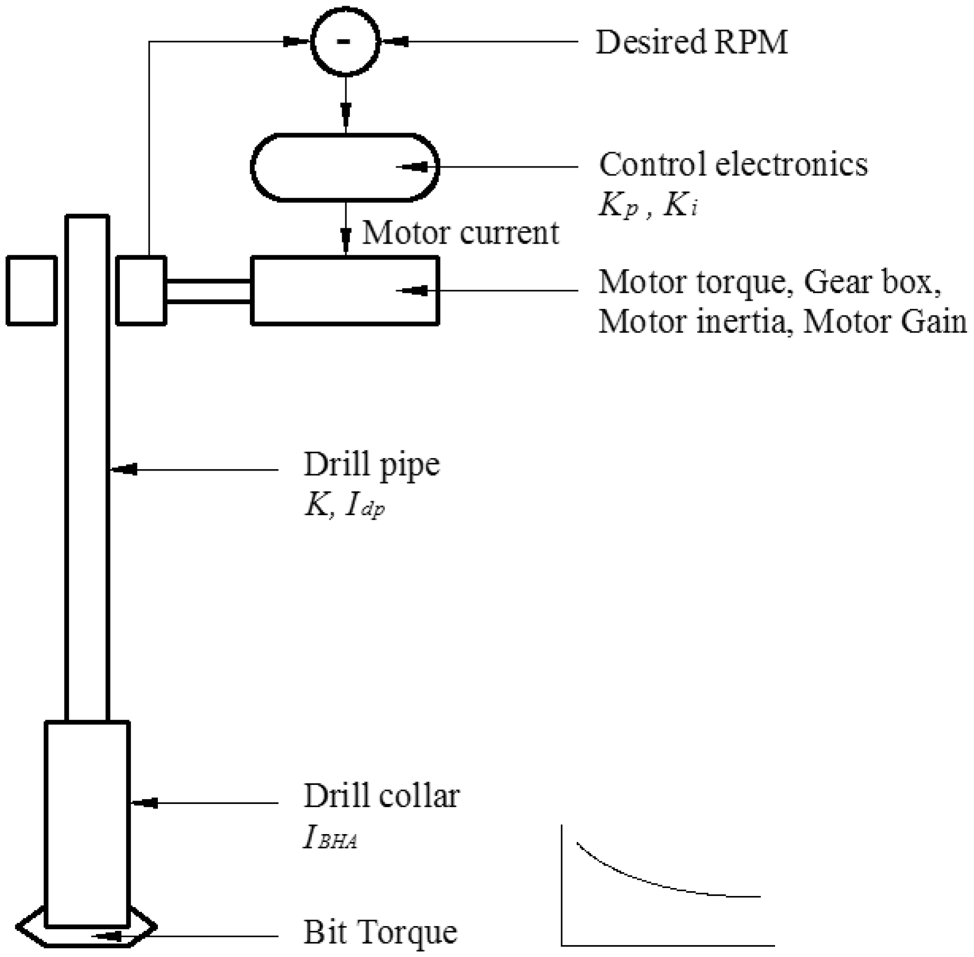
Lumped mass spring model of the drillstring. 12
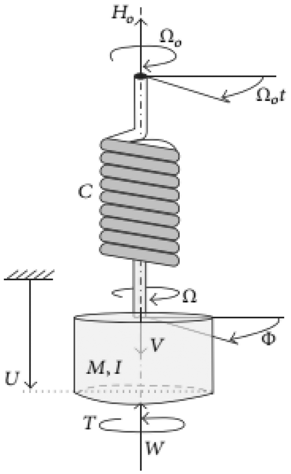
Rudat and Dashevskiy 13 modeled the drillstring as a mechanical oscillator with rotational SDOF (Figure 2). The model was used to determine optimal parameters by predicting the intensity of downhole stick–slip vibration. However, only the steady state responses were presented. By using a SDOF model similar to the one shown in Figure 2, Qiu et al. 14 studied the stick–slip vibration of drillstring. In the model, the bit-rock contact was modeled as random friction, and the stick motion and slip motion were treated separately. For the purpose of verifying the model, Monte Carlo simulation was conducted.
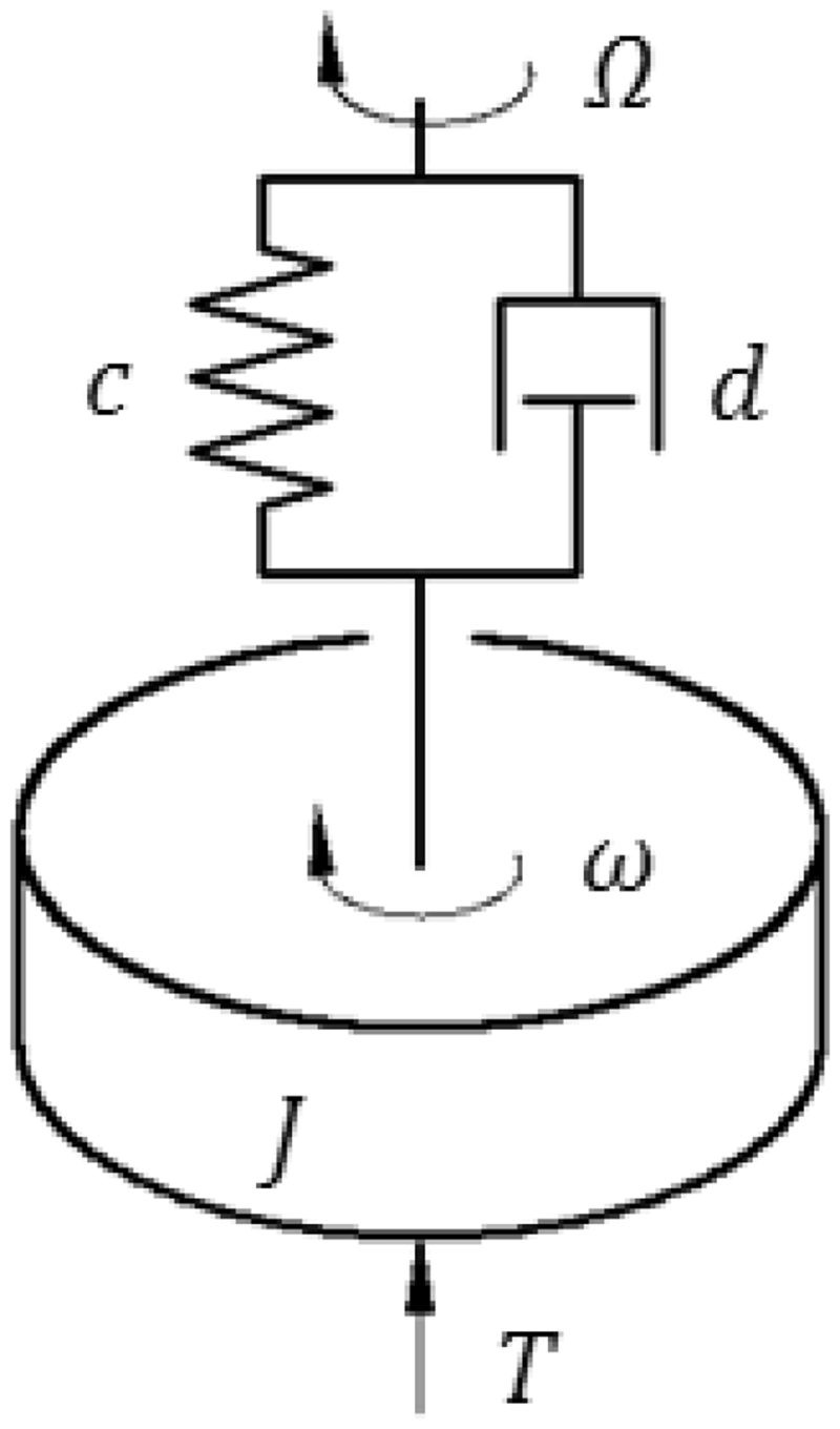
Mechanical SDOF model of the drillstring. 13
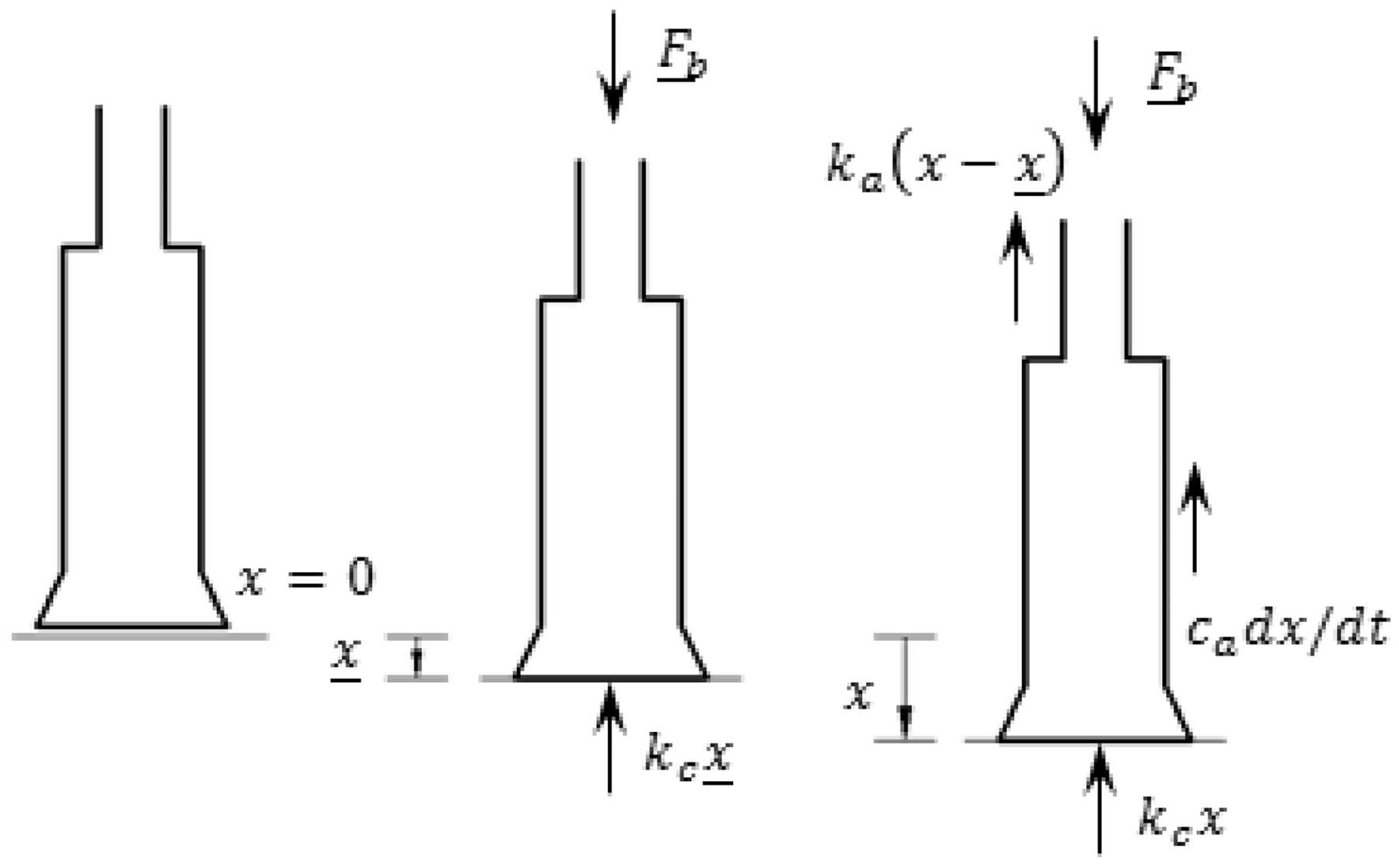
Even simple lumped mass model with actual drilling parameters can reproduce complex nonlinear drilling dynamics processes. Cunha-Lima et al. 15 developed a simplified SDOF model to study the torsional stability of the drillstring, for better understanding the causes of stick–slip phenomenon and the way to mitigate it. Based on this model, a similar mechanical model was developed by Tang et al.16–18 to study the effect of drilling parameters on stick–slip vibration (Figure 3). Results showed that the rotary table velocity, the friction coefficients, and viscous damping have significant effect on both the occurrence of stick–slip vibration and its dynamics.
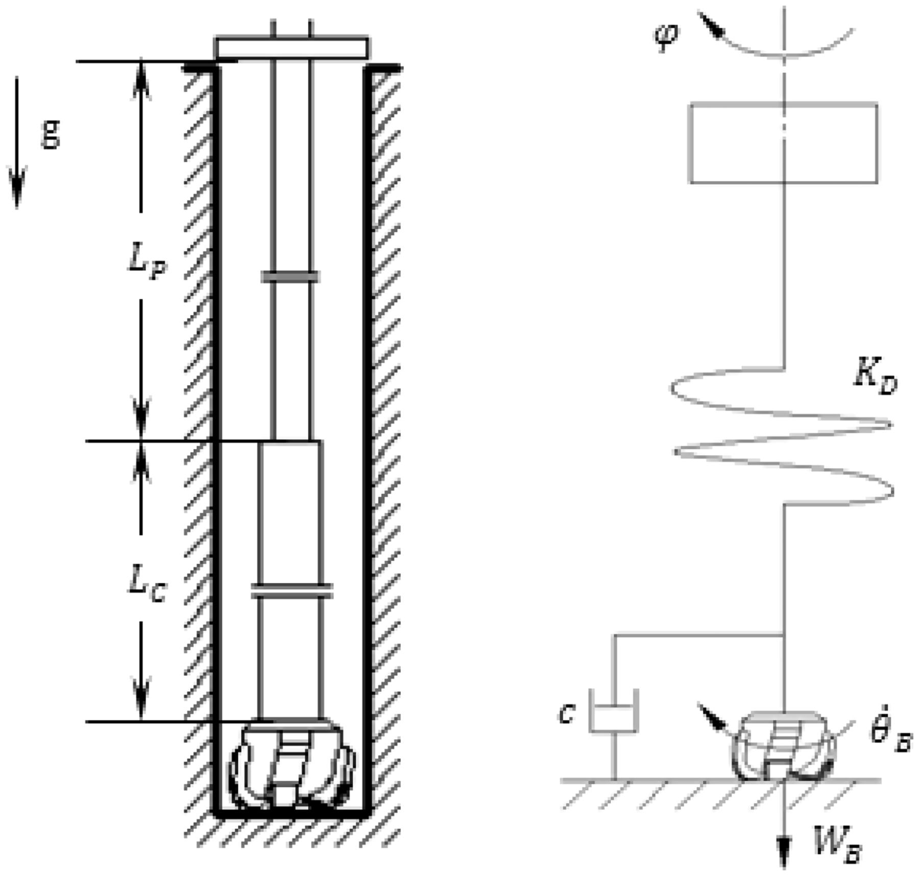
Analytical model of the drillstring system. 16
Another type of SDOF model used to investigate the stick–slip is the block-on-belt model,19,20 shown in Figure 4. Van de Vrande et al. 21 developed a SDOF block on belt model to study the stick–slip motion of drillstring. Periodic stick–slip vibration can be found by applying the smoothing procedure and simple shooting method with an ordinary differential equation (ODE) solver.
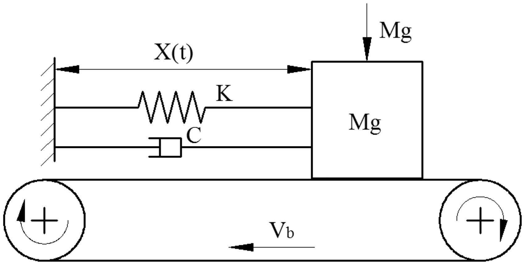
The block-on-belt model. 21
MDOF vibration models
Compared to SDOF, MDOF models can catch more details of the drilling system. Consequently, many investigations focused on stick–slip vibrations by using MDOF vibration models. Abdulgalil and Siguerdidjane 22 developed a simple dual DOF (DDOF) model (Figure 5) of stick–slip vibration by regarding the drilling system as a torsional pendulum. The assumption in this model is not always true, because the friction behavior can change easily due to the drilling condition variations.
Drilling rotary model by Abdulgalil and Siguerdidjane. 22
Canudas-de-Wit et al. 23 developed a similar open-loop plant model (Figure 6) as used by Rudat and Dashevskiy 13 with different boundary condition, where the assumption that rotary speed is constant. The friction-induced limit cycles were studied and the weight on bit (WOB) was used as a control parameter to extinguish limit cycles. Based on this type of DDOF model, Navarro-López and Suárez 24 reproduced the stick–slip motion in various operating conditions. Bayliss et al. 25 investigated the mitigation of stick–slip phenomenon in the drilling system via an online-identification-based adaptive design; Karkoub et al. 26 used genetic algorithms (GAs) to optimize stick–slip responses.
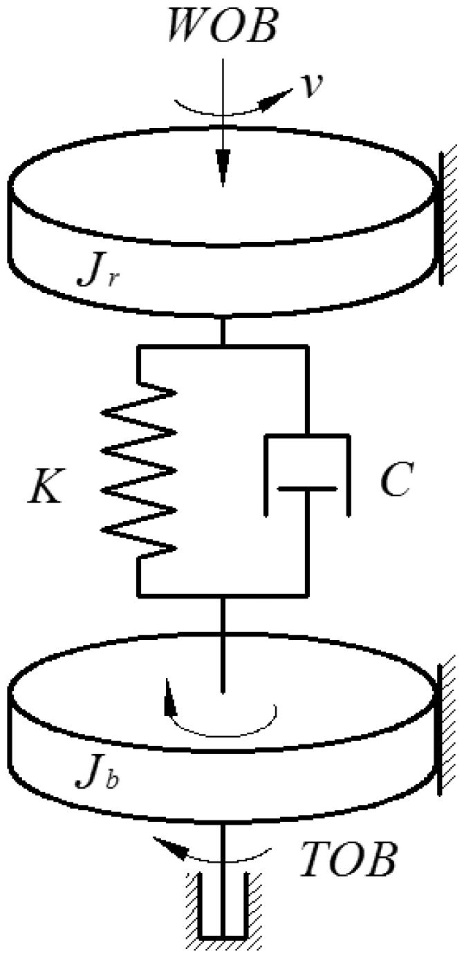
The DDOF model by Canudas-de-Wit et al. 23
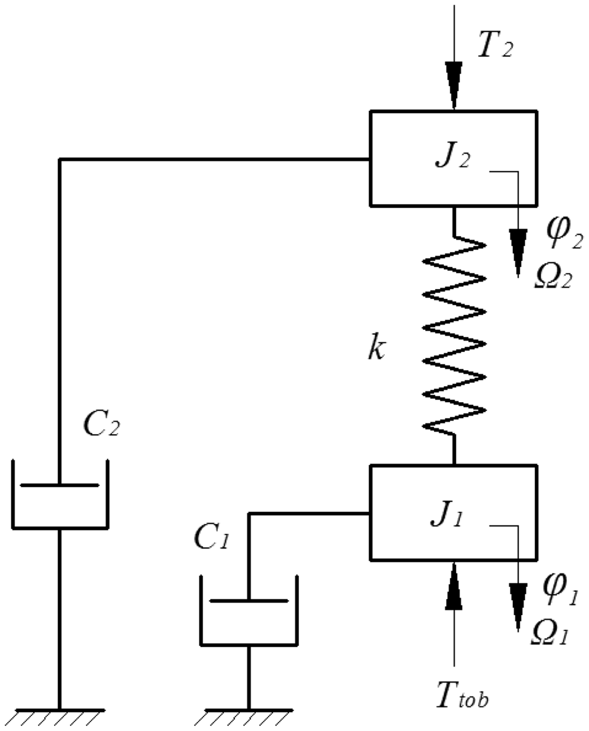
Silveira and Wiercigroch 27 evaluated the bit-rock interaction and developed a three DOF (TDOF) torsional pendulum model to investigate the drillstring stick–slip behavior. Patil and Teodoriu 28 developed a TDOF stick–slip model (Figure 7) and studied the effects of influencing parameters such as rotary table velocity and WOB on stick–slip vibration, where the nonlinear friction forces represented the bit-rock interaction.
The TDOF torsional pendulum model by Patil and Teodoriu. 28
Navarro-López et al.29–31 discussed a more generic discontinuous torsional model of four DOF (FDOF) (rotary table, drill-pipes, drill-collars, and drill bit), shown in Figure 8. Based on this model, a sliding motion leads to self-excited vibrations and bit stick phenomena at the BHA were analyzed. The key drilling parameters were determined by investigating Hopf bifurcations.
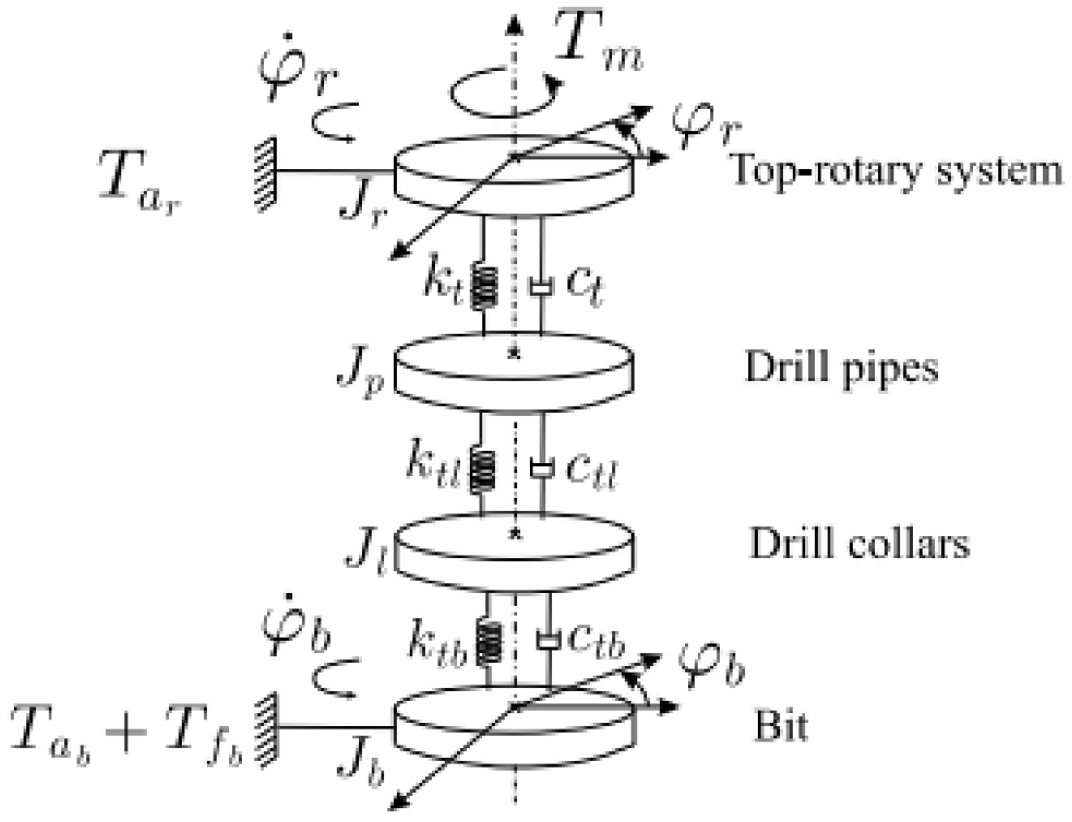
The FDOF lumped pendulum model describing the stick–slip vibration of a drillstring. 31
Kreuzer and Steidl 32 developed a high dimensional drillstring model consisted of 51 elements, one element represents the rotary table, one element represents the BHA, and 49 elements model the string with self-excited stick–slip vibration.
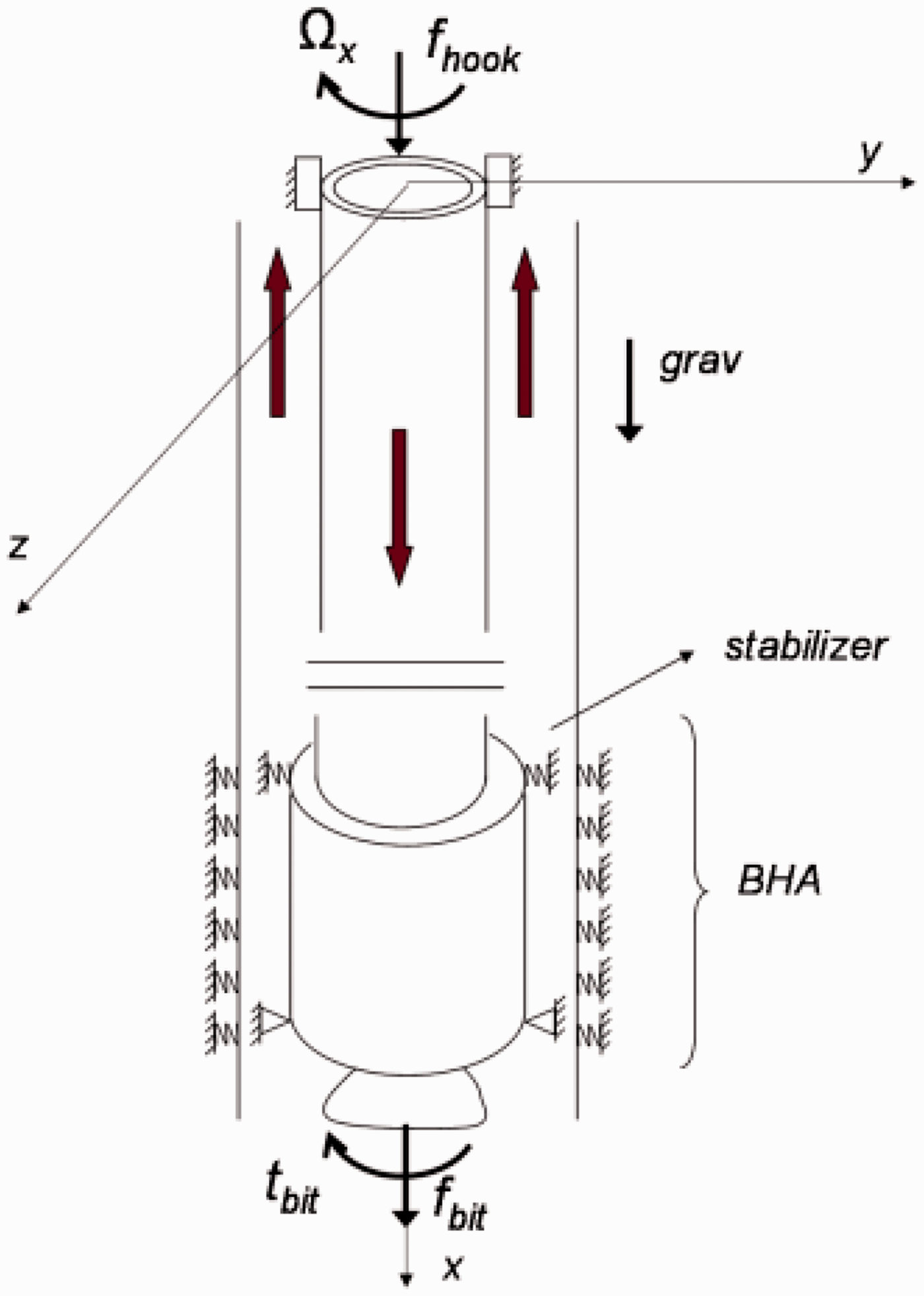
The finite element (FE) method was used to model drillstring; however, most of the reported investigations concentrated on investigating the BHA. In order to understand the severe torsional and axial vibrations excited by stick–slip vibration, Khulief et al. 33 used Lagrangian method and FE method to derive the motion equation of the rotating drilling system. The drillstring model included both drill-pipes and drill-collars to study the dynamics of the drilling system in the existence of stick–slip vibrations. Kapitaniak et al. 34 developed a detailed MDOF model of a drilling system using FE method to calibrate a TDOF mathematical model, in particular when stick–slip vibration occurs.
Distributed vibration models
A high dimensional or infinite model can describe typical features when modeling an engineering system. But these models are computationally expensive. Palmov et al. 35 studied the stick–slip vibration of drillstring basing on a distributed vibration in torsion, considering the BHA to be a rigid body. Based on this model, studies have tried to interpret the instability initiation that results in stick–slip phenomenon of drillstring. Challamel36,37 proposed the direct method of Lyapunov to study the stability conditions of a distributed drillstring model. The stability of a drillstring relatively forms the bit-rock contact depending on the rock crushing process. Simulations illustrated that the bit converges towards stick–slip vibration with a typical limit cycle. Results also showed that the stick–slip vibration behaves for polycrystalline diamond composite (PDC) bit with small variation of axial velocity and justifies the use of an uncoupled torsional model. However, bit-rock interaction experiments with single cutters may not reveal the intrinsic velocity weakening effect. Further investigation in this field was done by Saldivar et al.38,39 In the study, a friction model similar to the one by Navarro-López et al.29–31 was presented. D’Alembert transformation and Laplace transform were used to analyze and simulate the drillstring behavior. By investigating the occurrence of stick–slip vibration, some approaches for mitigating stick–slip vibration were put forward by manipulating BHA characteristics.
Kreuzer and Steidl 40 presented the wave equation for the torsional dynamics of the actual drillstring. Two principles were revealed: (a) existing a range of the drillstring rotation angular velocity where the stick–slip motion of the drillstring takes place, and (b) the process of stick–slip vibrations and their forms are independent of the initial conditions.
Almost all the previous investigations focused only on stick–slip vibrations in the torsional direction. Ritto et al. 41 thought that only one contact point at the bit-rock interaction in vertical wells exists. In horizontal drilling, nevertheless, there is stick–slip in the axial direction because of frictional force. Under this circumstance, they proposed a stochastic model taking into account the friction force between the drillstring and the borehole. Combining FE method with Monte Carlo method into the bar model, stick–slip behavior in the axial direction was obtained. For such bit-rock interaction model, the stochastic friction forces and the parameters selection are sources of uncertainties. In a latest work by Ritto, 42 identification of factors of the bit-rock contact model was investigated. In order to control stick–slip vibration through startup trajectory design, Aarsnes et al. 43 presented a distributed model of drillstring to replicate the stick–slip vibration caused by transition of static and dynamic frictions. This work was followed by a distributed axial-torsional drillstring model to investigate the appearance and global characteristics of self-excited vibrations caused by the regenerative effect of bit-rock interaction. The investigation showed the effect of bit rotation rate on the excitation of multiple axial and torsional modes of the drillstring. In addition, a stability map of the slick–slip vibration was presented. 44
Stick–slip vibration coupling models
The vibrations in the drilling system are usually divided into three fundamental types: axial, transverse, and torsional modes, with different patterns of manifestation. Bit bounce, whirling and stick–slip are extreme states of the axial, transverse and torsional vibrations, respectively. 45 The causes of these vibrations include the interaction between the drillstring and borehole, bit-rock interaction, unbalance of curvature of the drillstring, and variation of the drilling parameters. These motions are usually complex and are coupled together or occur simultaneously. 46 A number of publications studied the coupled vibration of drillstring, including lateral–torsional, lateral–axial, and axial–torsional coupled models. The coupled models related to stick–slip vibration are to be reviewed in this section.
Stick–slip and bit bounce coupling models
Based on the simplified lumped model by Christoforou and Yigit, 46 Yigit and Christoforou 47 simulated the influences of operating conditions on bit bounce and stick–slip. It indicated that conditions at the interface of bit and rock are major factors of bit dynamics. Noted for the presented model, a number of parameters that should be determined by experimental measurement were included.
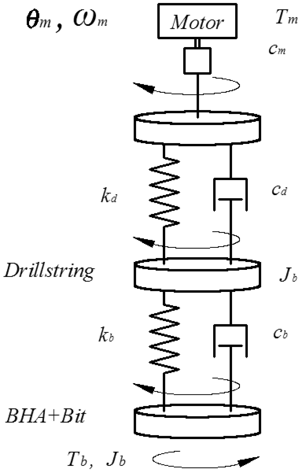
The stick–slip vibration modeling typically considers only the torsional vibration of drillstring regarding the interaction between the bit and rock as Coulomb friction referred to velocity weakening. 36 Richard et al.48–50 proposed a DDOF discrete model (shown in Figure 9) considering the axial and torsional vibrations of the drilling system to study the self-excited stick–slip phenomenon. Coupling between the two vibration modes was realized by using a bit-rock contact principle where the friction and crushing processes were considered, which differed from the classical method used to reveal the stick–slip vibration. The dynamic responses can be obtained by the surface conditions of the drill bit and bit-rock contact principles, in conjunction with the motion equations for the torsional and axial vibrations. The model was restricted to an idealized drag bit that includes many identical radial blades distributed uniformly along axis of revolution of the drill bit (see Figure 10).
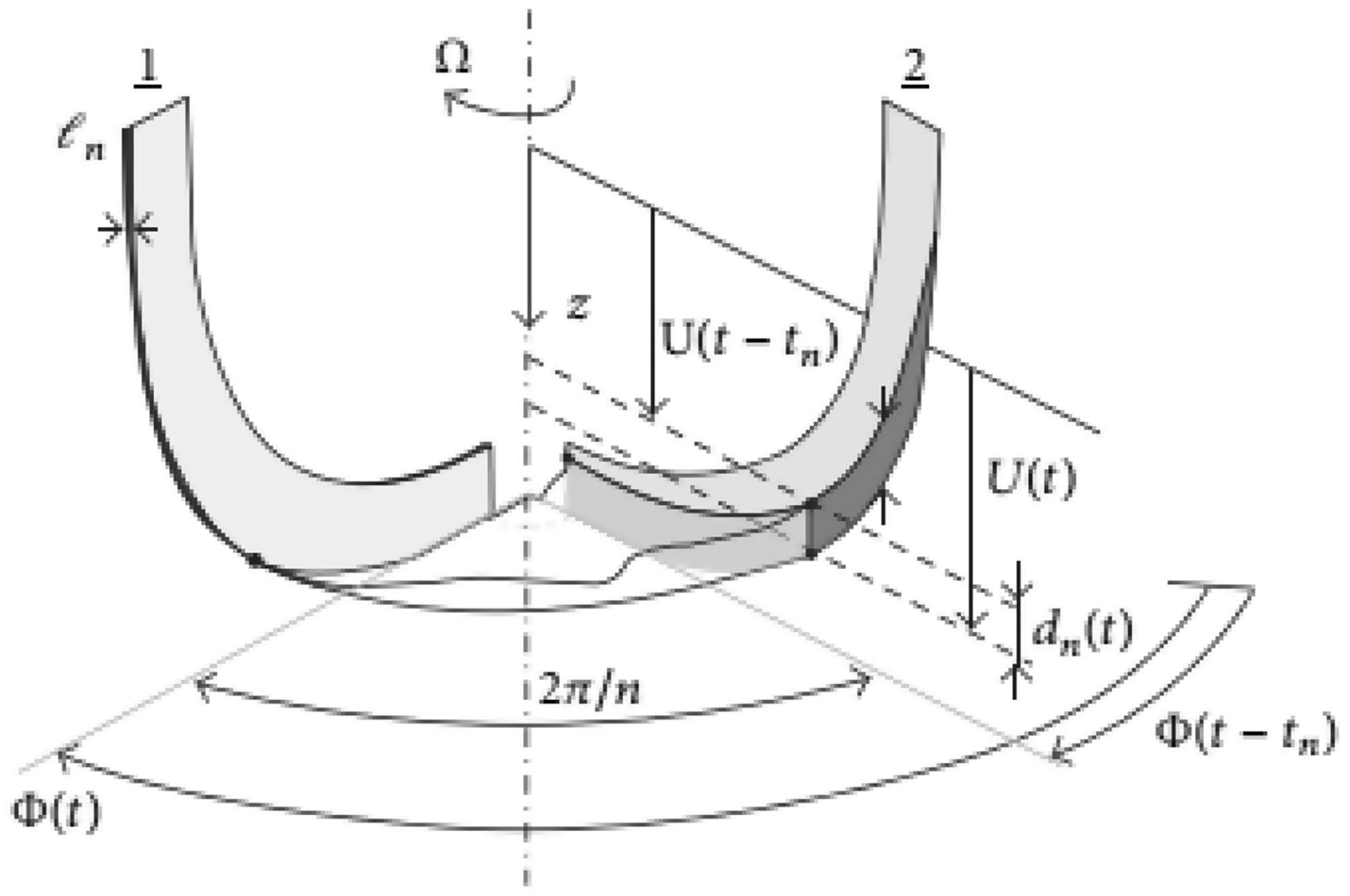
For the developed model, a delay was introduced into the cutting process, leading to the occurrence of self-excited vibration that degenerates into stick–slip or bit bouncing for some conditions. In this model, the WOB was considered as a constant and this can be realized by adjusting the hook load, which means the axial displacement of the drillstring must be controlled at the surface to match the bit movement. The drill bit, however, encounters severe axial vibration and thus is difficult to realize the proposed condition. The model neglected the dynamics of the delay-based effect on the assumption of a timescale separation between the axial and torsional dynamics.
Based on the model by Richard et al.,49,50 Germay et al. 51 identified the mechanisms of axial and torsional vibrations and their parametric dependence. The investigation of decoupling axial and torsional dynamics provided an interpretation for the occurrence for most dynamic regimes. Germay et al. 52 expanded on the model of Richard et al. 49 by using continuous system model (also called distributed model) rather than a DDOF lumped model. The drillstring dynamic responses were studied using the FE method and some new features in the stick–slip vibration were detected. However, this model is always unstable according to a recently linear stability analysis by Nandakumar and Wiercigroch. 53 In order to identify the exact origins and interplay of stick–slip and bit bounce, they proposed fully coupled DDOF model with a viscous damping and a state-dependent time delay.
Many other studies54–56 presented the coupled stick–slip phenomenon and bit bounce with a basic model by Richard et al.49,50 Kamel and Yigit 57 studied coupled axial and torsional behaviors of a drillstring through utilizing a DDOF lumped pendulum model where Lagrangian approach was used to estimate the equivalent system parameters and a new cutting and interaction model was used to describe the bit-rock contact. It was shown that the stick–slip motion and bit bounce could be minimized by proper choice of the operational parameters. Kovalyshen 54 considers the resonance between the cutting force and natural vibration modes as the reasons of drillstring vibration, and carried out a stability analysis of coupled vibrations of a drilling assembly. It demonstrated that the driving mechanism of the axial vibration mode is the regenerative effect, while the driving mechanism of the torsional vibration is the crushing process of the bit and the bit/rock contact. Based on this study, a root cause of stick–slip coupled with bit bounce was revealed.
Alamo and Weber 58 obtained a mathematical model to investigate the torsional vibration, considering the longitudinal vibration. For the stick–slip vibration model, the top rotates have a constant rotary speed and the bottom end are subjected to a cutting force which represents the bit-rock interaction. Finite difference was used to discretize the space domain and Runge-Kutta method was employed to obtain the time response. Results showed that the coupled model could describe the stick–slip vibration depending strongly on the rotary table velocity. Sampaio et al. 59 considered the geometrical nonlinearity in modeling the coupling of axial and torsional vibrations. By using FE method and taking into account the large rotations and nonlinear strain displacements, linear and nonlinear models were compared. It showed that the linear and nonlinear models differ comparatively after the first period of stick–slip.
Based on the mechanical model proposed by Christoforou and Yigit 46 considering the axial and torsional behaviors of drillstring, Divenyi et al.60,61 developed a DDOF lumped parameters model (see Figure 11) to study the coupled axial and torsional motions where the coupled vibration was regarded as being induced by the bit-rock contact and the axial force was regarded as the catalyst of generating a resistive torque. The analyzed results show that the model is able to predict a full range of dynamic responses including the stick–slip vibration and bit bounce and to understand the drillstring dynamics and critical behaviors of the system by using different scenarios related to parameter changes. However, a number of parameters should be determined by experimental measurement. Particularly, measuring the parameters is challenging. For the complex drilling process, the parameters in the model changed easily. More field data used to verify and optimize the model are needed.
Basing on a DDOF model with coupling torsional and axial vibration, Vasconcellos and Savi 62 conducted a parametric analysis of the transitions between different motion phases and the non-smooth dynamic responses of stick–slip and bit bounce. Sarker et al. 63 applied a bond graph model of the drilling system to predict axial and torsional vibration, and coupling between the two vibrations due to bit/rock contact. Ertas et al. 64 used transfer matrices to solve small torsional vibrations around a baseline solution in the frequency domain, accounting for well path, tool joints, viscous damping, surface boundary condition, bit features, and special vibration mitigation tool. Sairafi et al. 65 established a coupled stick–slip and bit bounce model with the driving system and hoisting system. Results demonstrated that controlling only torsional vibration is not effective in suppressing bit bounce phenomena and an axial controller should be implemented as well.
Earlier studies for drillstring dynamic model lacked two essential features: the axial stiffness of the drillstring and friction from along the drillstring. Besselink et al. 66 investigated the mechanisms leading to stick–slip using a model that includes axial motion, torsional motion, and a rate independent bit-rock contact law. It showed that the axial stick–slip phenomenon is dependent on the rotational bit speed and that the generation of torsional stick–slip phenomenon is driven by the axial motions, which means that mitigation of axial vibrations may also suppress torsional vibration. Besselink et al. 67 furthered the work of mitigation of stick–slip vibration by using feedback control strategies.
Previous works postulates that self-excited vibrations occur because of the coupling between the drillstring and the regenerative effect in the bit-rock contact law. 68 To prove this, Aarsnes and Aamo 69 studied a graphical condition for stability of drillstring based on the Nyquist stability criterion.
Stick–slip and whirl models coupling
A time domain dynamical model allows the prediction of drillstring dynamics related to torsional and lateral vibrations. By using FE approach, Schmalhorst and Baumgart 70 developed a nonlinear drillstring model taking into account arbitrarily shaped assemblies during drilling of curved boreholes. In the model, restitution forces act on the drillstring and contact velocity-dependent friction forces were introduced. The torsional and lateral DOF were coupled and the whirl and stick–slip phenomena combined with normal drilling conditions were solved numerically. Abbassian and Dunayevsky 71 studied the stability of bit dynamics through a coupled torsional–lateral vibration model.
Whirling and parametric resonances of drillstring have been investigated.72–74 In these investigations, the rotary table velocity was regarded as a constant and the torsional vibration was not included. Based on this, Yigit and Christoforou 75 considered the coupling between the lateral and torsional motions of drillstring and assumed the excitation at the bit to be related to the bit rotation. The motion equations for coupled torsional and lateral motions were established through a simplified model shown in Figure 12.
The simplified drillstring model with equivalent lumped parameters. 75
Apart from the strong coupling and nonlinear features included in the model, a consistent model was utilized to characterize the impacts of drill collars with the borehole. Results showed that there is significant energy transfer between the torsional and lateral motions at certain frequencies and that adjusting the surface torque is more efficient in eliminating the stick–slip vibrations. In another work of them, 76 the rotary drive system was also included in the mechanical model. Based on the results obtained from theoretical analysis, a linear quadratic regulator controller was designed to mitigate the stick–slip and whirl motions.
Drillstring vibration is highly nonlinear and the mechanical model can only be established by a group of nonlinear differential equations. The linear control approaches are not accurate for controlling the coupled lateral and torsional vibrations. Based on the mechanical model presented by Yigit and Christoforou, 75 Al-Hiddabi et al. 77 developed an inversion control design method based on nonlinear differential equations to control the torsional and lateral vibrations.
In order to interpret the complex drillstring motions where stick–slip vibration and lateral whirl are involved, Leine et al. 78 developed a simplified lumped stick–slip whirl model of the drilling system. The model exposes only the basic phenomena but was discontinuous. For this model, discontinuous bifurcations are obtained, providing explanation for the disappearance of stick–slip phenomenon when whirl motion appears. However, the experimental results were obtained by averaging the torque on bit over several revolutions and may not hold at a more relevant time scale.
Melakhessou et al. 79 proposed a FDOF mathematical model to investigate the stick–slipt and whirl vibrations, with lateral movement, rotation of the section, bending around thetangential orientation, and torsional displacement of the drillstring were included. Field cases showed that stick–slip and whirl can be eliminated when a roller reamer is introduced. Sowers et al. 80 developed a conceptual model coupling stick–slip and whirl in order to understand the mechanism of roller reamers improving drilling performance by decoupling or suppressing drillstring vibrations. Vlajic et al. 81 presented a distributed parameter model (Figure 13) to describe the coupled bending and torsional vibrations while the interaction forces between the drillstring and the wellbore were taken into account. Both the whirl and stick–slip phenomena were investigated numerically and the results were compared with the experimental results.
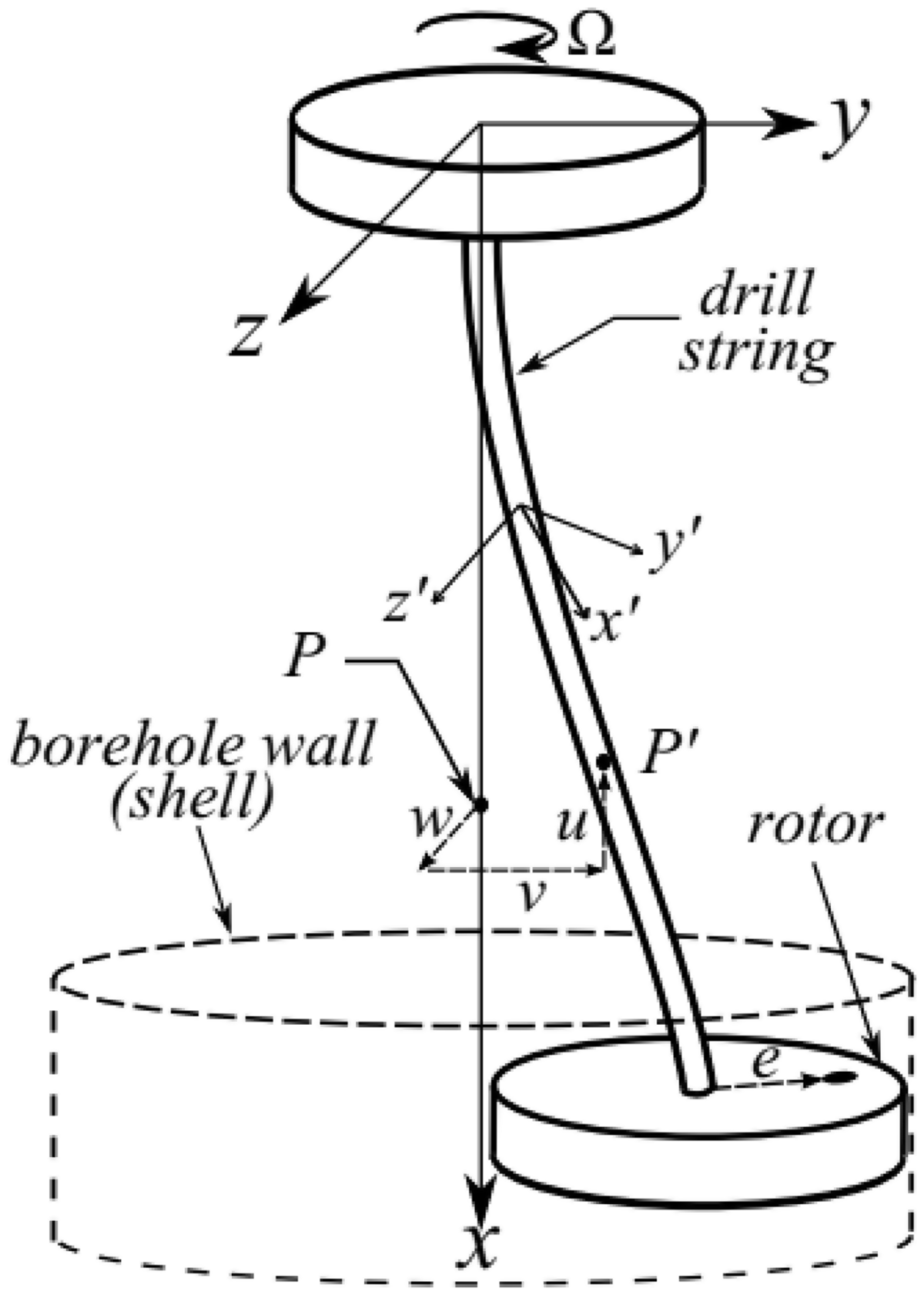
A schematic depicts the drillstring model. 81
Butlin and Langley 82 claimed that drillstring dynamical models contain three features (1) efficient so as to conduct parametric investigation, (2) simple so as to reveal the underlying mechanisms, and (3) retain enough details to associate real conditions. By using a reduced order model that takes into account the nonlinear interaction laws and solving by time domain integration, results from cases studies demonstrated the occurrences of a number of phenomena, including stick–slip vibration and whirl. Apart from the mathematical models, field tests on the stick–slip and whirl were also carried out by many researchers.2,81,83–85
Fully coupled vibration models
Tucker and Wang86–88 proposed a torsional rectification mechanism to study stick–slip and compared it with existing soft-torque devices via several mathematical models. It shows that the approach proposed can eliminate many of the volatilities suffered by the existing suppression approach used to control stick–slip vibration. Baumgart 89 derived a fully coupled mathematical model for the drilling process and solved it as an initial value problem. For the nonlinear differential equations of motion for the drillstring, the axial, lateral and torsional motion of the drillstring as well as the flow rate, the mud pressure, and buckling were included. WOB and torque on bit were obtained from characteristic curves, which are functions of the penetration rate, and the angular bit velocity. Results showed the self-induced characteristics of the stick–slip and bit bounce phenomenon. However, discussions on the lateral vibration results were not included.
Christoforou and Yigit4,46 claimed that bit-rock and drillstring-borehole interactions as well as the geometric and dynamic nonlinearities give rise to the coupling of the drillstring vibrations. They presented a fully coupled model for the three basic modes of vibration of actively controlled drillstring with the mutual dependence of these vibrations. The model was similar to the one presented in Figure 15. It showed that torsional vibration due to bit motion excites axial and lateral motions leading to bit bounce and impacts with the borehole. An active control strategy was proposed to control the stick–slip vibration of the drilling system.
Khulief and Al-Naser 90 developed a 12-DOF FE model for drillstring with the coupling vibration and gyroscopic effects were considered. The reduced order model was obtained by modal transformation, and the modal features and lateral dynamics of the drillstring at the drill bit were presented. Khulief et al. 91 presented a dynamic drillstring model accounting for the axial-bending vibration and the torsional-bending vibration. The gyroscopic effect, the gravitational force, and the drillstring-borehole impact were considered, wherein the force–displacement principle was applied to describe the impact force and the energy balance relations were used to determine the viscous damping.
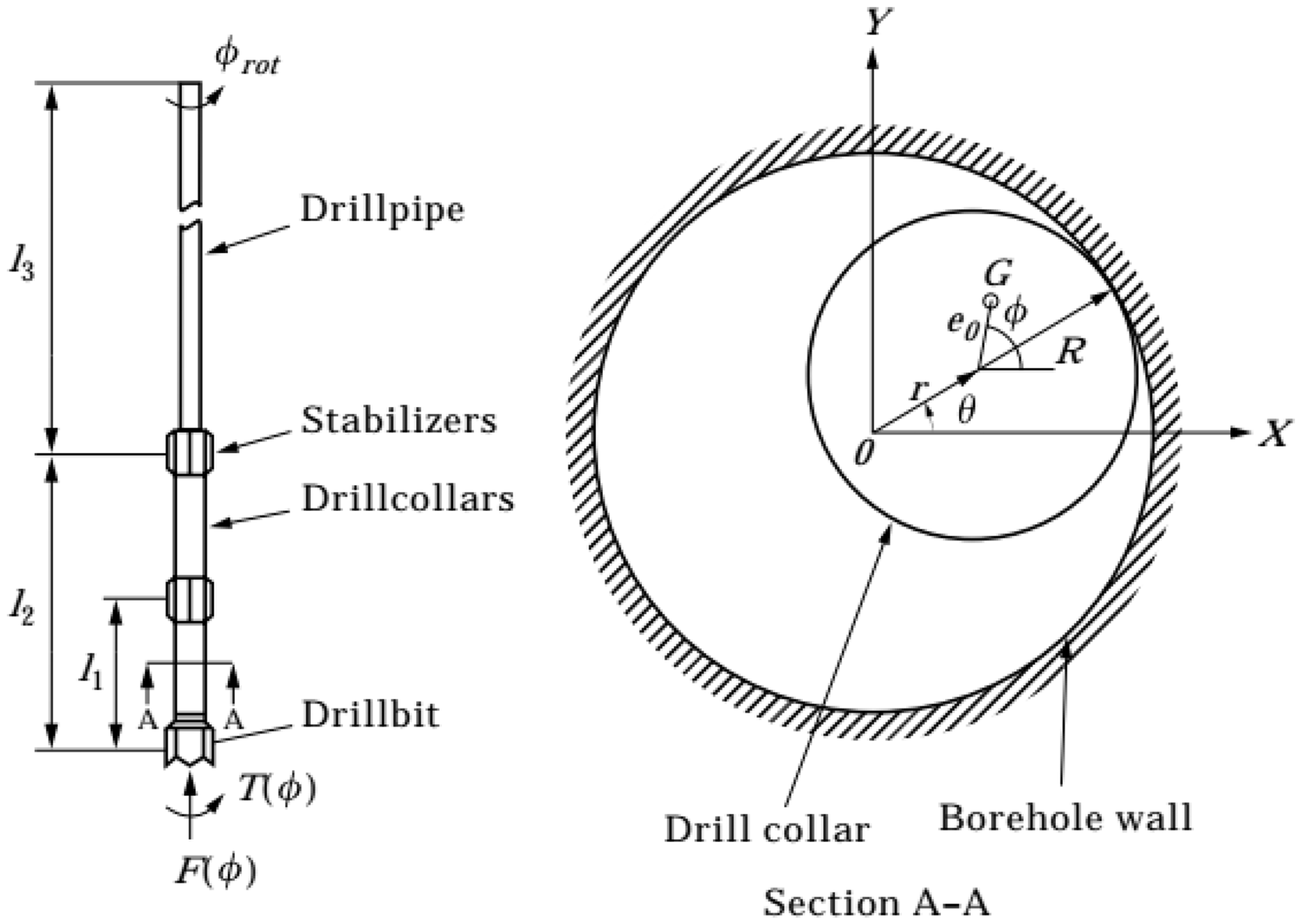
By using Timoshenko beam theory, Ritto et al. 92 established a numerical model to investigate the effect of the drilling fluid on the dynamics of the drillstring (Figure 14). A simplified fluid–structure interaction model accounting for the mudflow in and out of the drillstring was used. Other factors such as rotation and hanging force at the top, bit-rock interaction, shock and rubbing on the drillstring, weight of the drillstring, and finite strains that couple axial, lateral, and torsional vibrations were taken into account. However, the effect of fluid flow was not considered.
General scheme of the dynamical model. 92
Liu et al. 93 developed an eight-DOF discrete model of the drillstring to study its nonlinear vibrations, considering the axial, lateral, and torsional dynamics, shown in Figure 15. In the model, time-delay aspects, nonlinearities because of dry friction, loss of contact, and collisions were considered. Based on this model, numerical analyses were conducted for various drilling conditions. Results revealed that the drillstring behaviors can be self-excited due to stick–slip friction and time-delay effects and that the whirl motion of the drillstring alternates periodically between the stick and slip phases.
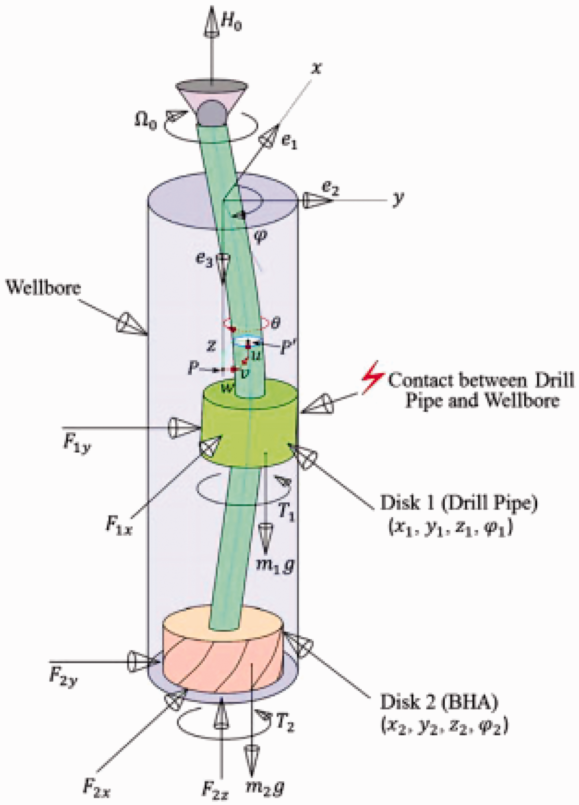
Schematic of the discrete drilling system model. 93
Liu et al. 94 analyzed the stability of the drilling system in terms of stability volumes in the space of rotate speed, cutting depth, and cutting coefficient. The stability volume provides a guide for choosing parameters for rotary drilling operations. Based on the state and delayed-state feedback, a control strategy was presented and the effectiveness of this approach to mitigate stick–slip vibrations was studied. These two works were extended with developing a 32 segments model, 95 and stability analysis of the degenerated one-segment model shows a stable region for the drilling operations.
For reproducing all major types of drillstring vibrations, Kapitaniak et al. 34 constructed an experimental rig where the commercial drill bits and rock samples were utilized. A mathematical model of the drillstring was presented by using low dimensional ODE model based on torsional pendulum. Various dynamical phenomena of the drillstring, such as stick–slip vibration, whirl, bit bounce, and buckling, were obtained. In a recent work by Moraes and Savi, 96 a FDOF nonsmooth model with including axial-torsional-lateral coupling was developed to study the drillstring vibration, considering bit rock, wellbore interactions, eccentricity of drillstring, and hydrodynamic force. By carrying out parametric studies, characteristics of stick–slip, bit bounce, and whirl motions were obtained.
Experimental investigations
Finnie and Bailey 97 conducted experimental tests to study the axial load, torque at the top of a drilling system. Fritz 98 did tests to investigate the dynamics of a vibratory rotor that paved the way for drillstring dynamics testing. For the drilling industry, comprehensive experimental facilities have been developed to characterize the bit performance. 99 These facilities have improved the understanding of the interaction between the drill bit and rock formation, resulting in high performance drilling tool and proper operation. The investigations reviewed in the following section focuses on the experimental studies of stick–slip vibrations in drillstring.
Laboratory studies
In order to identify the vibration effects on bit performance, Chen et al. 100 designed a number of laboratory facilities and field tests. Results showed that roller cone bit may encounter stick–slip phenomenon under some drilling conditions and stick–slip motion does not adversely influence the penetration rate.
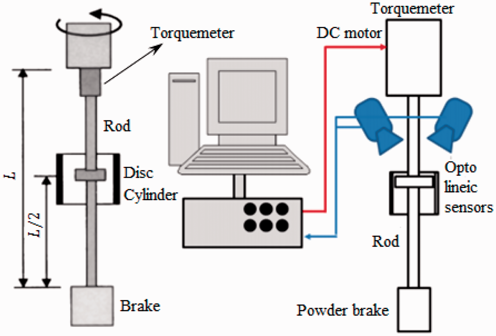
Melakhessou et al. 79 developed a FDOF model to study the interaction between the drillstring and the wellbore during the drilling process. The nonlinear equations for describing the model were solved numerically. For verification, experimental setup was used including two opto-electronic devices, 101 as shown in Figure 16. The dynamic features obtained from model analysis were compared with the experimental results. It showed that the simulation results agreed with experimental observations when stick–slip vibrations occur.
For better understanding the causes of stick–slip vibration, Mihajlović et al. 102 developed an experimental drillstring setup and torsional oscillation with and without stick–slip were observed in steady state (see Figure 17). A Lyapunov-based stability study and numerical and experimental bifurcation analyses were conducted. 103 A comparison between theoretical and experimental bifurcation diagrams was carried out to know the predictive quality of the theoretical model. It showed that the friction characteristics were linked to the existence of torsional vibration with and without stick–slip. However, axial vibrations were not considered and coupled motions with considering stick–slip vibration have not been conducted.
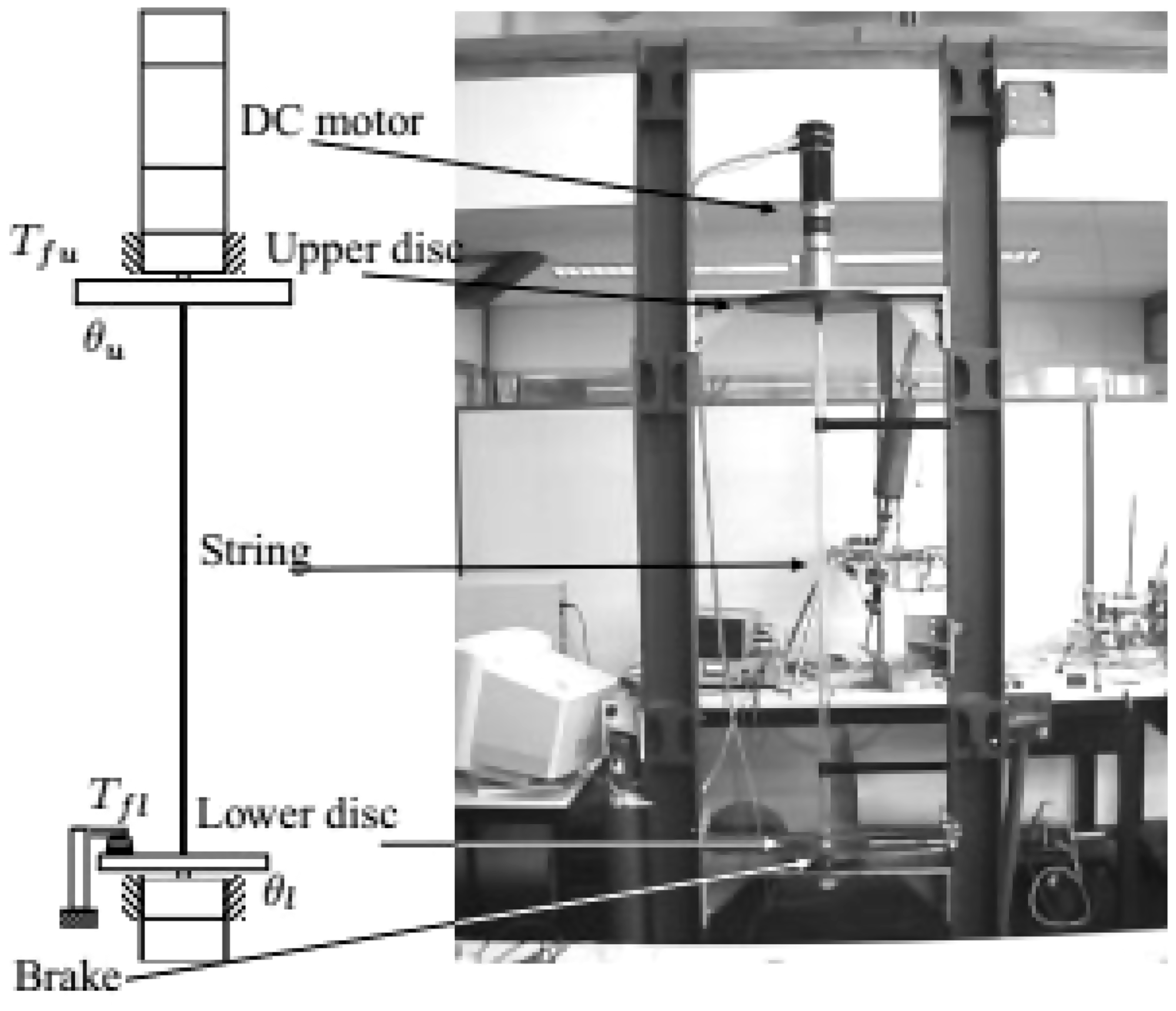
Experimental drillstring setup. 102
Khulief and Al-Sulaiman 33 designed a drilling test apparatus (Figure 18) that can reproduce the drillstring dynamics for different excitation mechanisms. The test apparatus includes a motor that can generate different speeds, a brake was used to produce stick–slip conditions, and a shaker was used to apply WOB. The experimental results were employed to input and tune some parameters applied in the elastodynamic FE model.
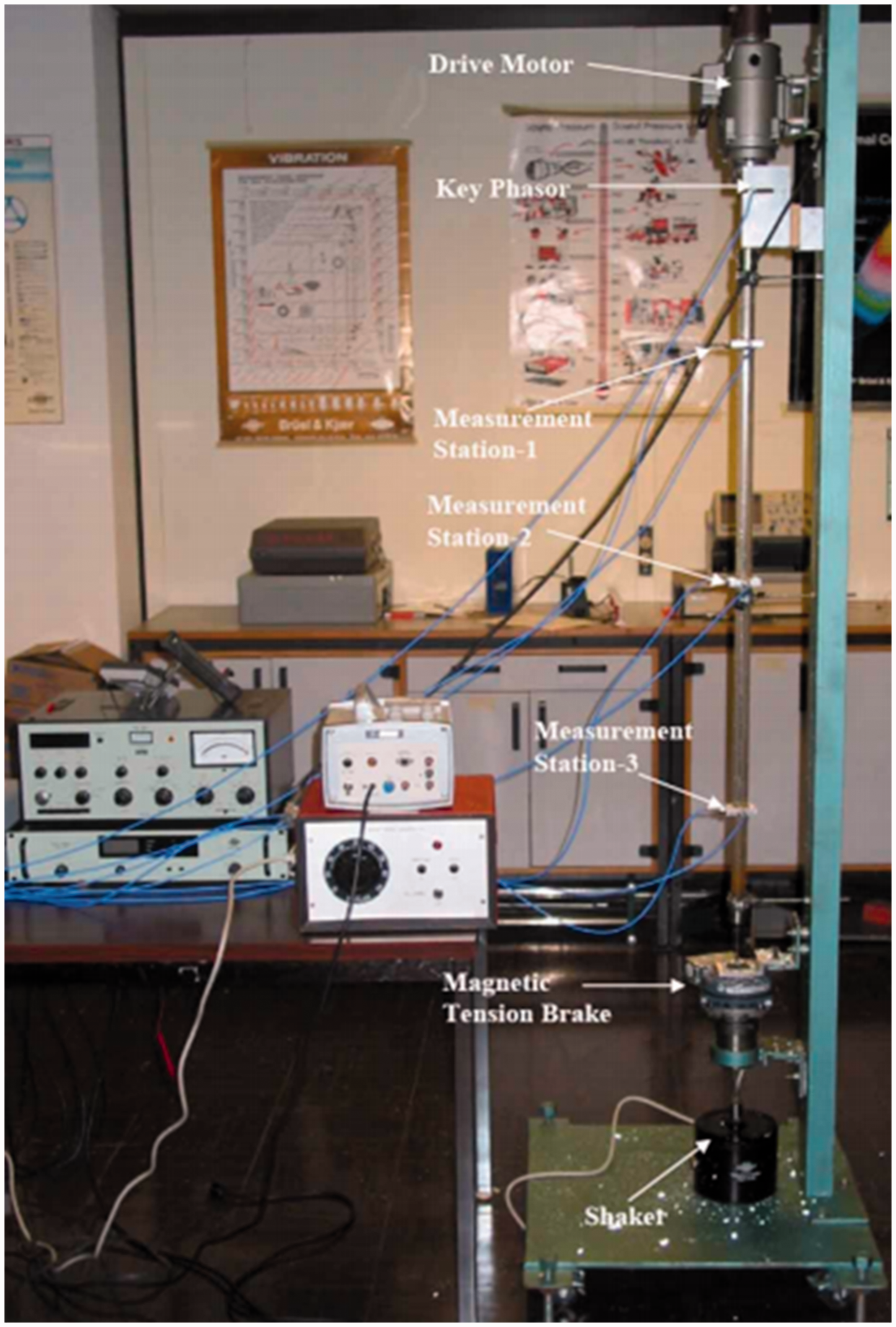
Photograph of the laboratory test rig. 33
Theoretical analysis by Canudas-de-Wit et al. 23 revealed that the stick–slip could be effectively controlled by applying an adaptation law (referred to as D-OSKILL) without requiring variations in the top drive and drillstring. Lu et al. 104 developed a laboratory setup to generate stick–slip phenomenon (Figure 19). For the experiments, the rotational speed and WOB applied onto the drillstring are 20 rad/s and 180 N, respectively. Results showed that the WOB is returned to the nominal values when the stick–slip is suppressed, which agrees with the simulation results. Experimental results also showed that ROP reduces when the D-ODKILL is used but the stick–slip vibrations are significantly minimized.
Laboratory setup to generate stick–slip phenomenon. 23
Forster 105 studied the mitigation of stick–slip vibration by introducing axial excitations into the drillstring. For this purpose, laboratory tests were conducted at the National Oilwell Varco Downhole Ltd. on small-scale vibration test apparatus designed to reproduce the stick–slip phenomenon and test different stick–slip reduction methods (Figure 20). For this setup, the tool performances with and without axial excitation can be tested. The axial excitation frequencies and axial load amplitudes of the typical axial excitation tools have been reproduced during the tests. It demonstrated that the axial excitations significantly mitigate the stick–slip vibration.
In-house built vibration test rig. 105
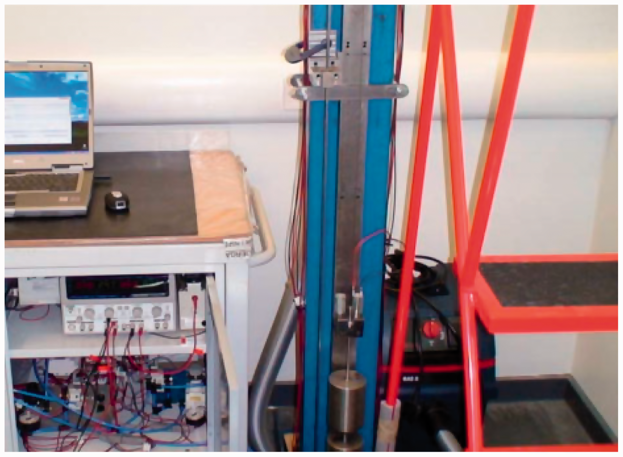
In order to facilitate the studies of the drilling system dynamics, Liao et al. 106 constructs a laboratory-scale drillstring setup to investigate the working conditions experienced by a drillstring, as shown in Figure 21. A variable speed motor was used to drive and two encoders were used to measure two discs. An unbalanced mass, which represents the drill bit, was attached to the bottom disc. Results showed that impact and stick–slip motions are observed at a low speed and that whirl is observed at a high speed. The experimental studies are beneficial to the reduced-order models in capturing the stick–slip vibration.
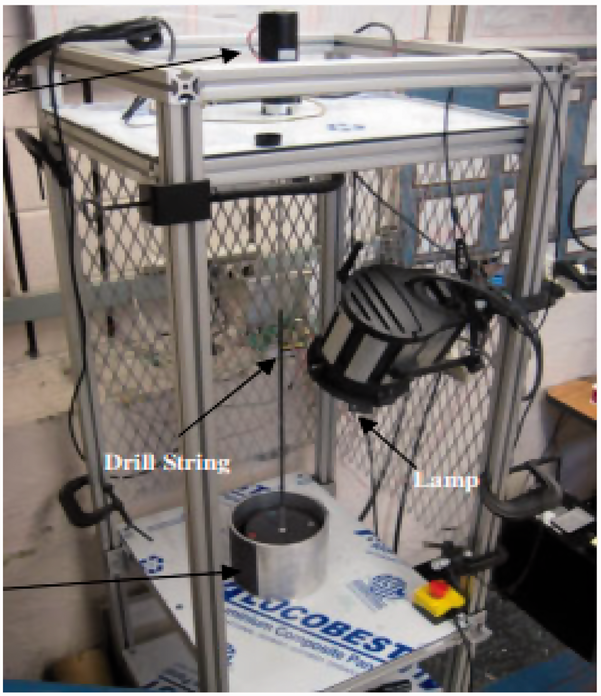
Laboratory scale arrangement of a rotary drilling system. 106
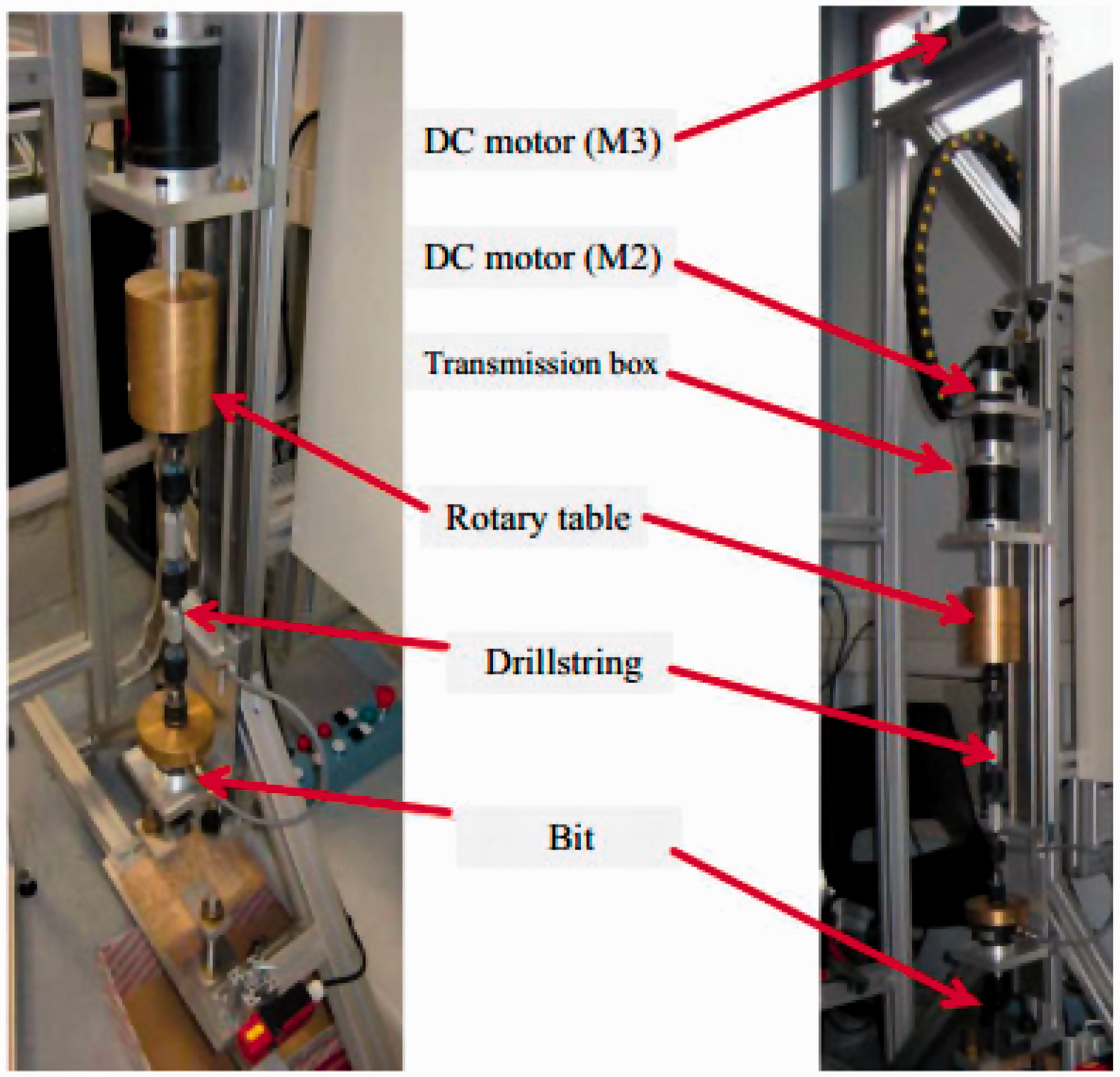
Patil and Teodoriu 101 reviewed comparatively the laboratory experiments of torsional vibrations and presented the experimental setup of drillstring at Clausthal University of Technology (as shown in Figure 22).
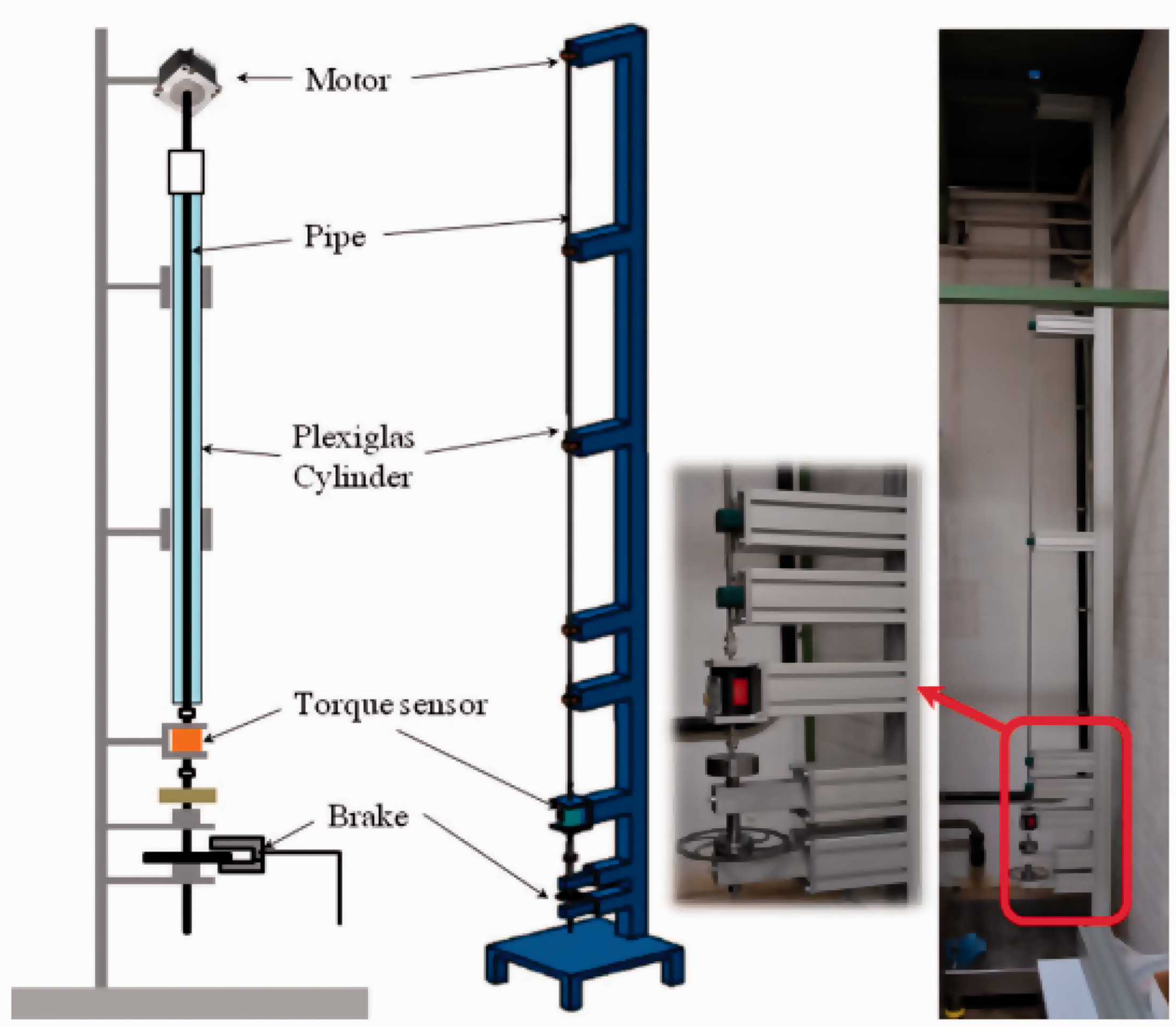
Experimental setup of the rotational drilling system at Clausthal University of Technology. 101
Results from the theoretical analyses on stick–slip 107 showed that the primary driving mechanism of stick–slip is not the self-excited axial vibrations, and not the velocity weakening effect but the crushing action of the drill bit and the interaction between the bit and rock. In order to verify this conclusion, Kovalyshen 54 presented the results of the ongoing experiments of stick–slip vibrations. Figure 23 shows the small-scale drill rig. It shows that the experimental results agree with the theoretical analyses.
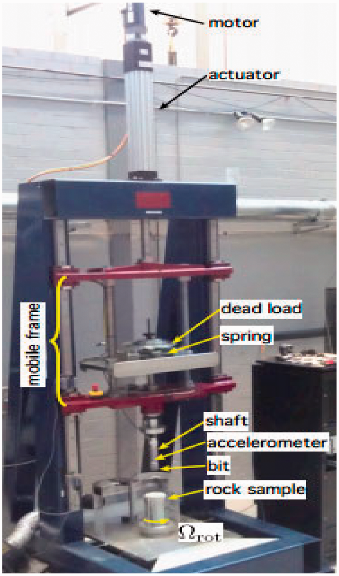
The small-scale drill rig. 107
Halsey et al. 108 studied the stick–slip vibration by conducting a comparison between theoretical analysis and experimental results based on a full-scale laboratory experimental rig. Raymond et al. 109 constructed a setup to obtain root understanding of BHA dynamics, but the tests are limited to the axial motions only. Detournay et al.110,111 developed a phenomenological model to investigate the cutting bit dynamics, WOB, torque, angular velocity, bit design, and cutter number are included, and experiments with a small drilling machine were conducted to verify this model. 112 Esmaeili et al. 113 constructed a full-scale drillstring rig, which actually drills into the rock sample. The laboratory apparatus consists of a steel frame, top drive, draw work, weights, measurement sensors, drill bit, drillstring, and a control unit. It has the ability of exerting 80 kg WOB on a bit of 2–3 inches. The relationships between drilling parameters with the ROP and drillstring vibration were obtained. Lines et al. 114 conducted laboratory tests to gain insight into the downhole data and characterize the stick–slip vibration of the rotary steerable system. Based on a simple test-rig for analyzing drilling dynsmic, Real et al. 115 explained the stick–slip cycles. As can be seen from the works related to laboratory tests of stick–slip vibration, there are differences among the test rigs. In fact, the performance of a test rig depends to some extent on the concentration of the theoretical model. Due to the complex behavior of stick–slip phenomenon, a small change on the rig (for example boundary condition of the drillstring) may lead to totally different results.
For most of the reported stick–slip phenomena, they were regarded as torsional vibrations. In a work by Wang et al., 116 the axial stick–slip motion of drillstring was reported. They built an experimental apparatus to investigate the toolface behavior in slide drilling. Results indicated that axial stick–slip vibration appears in the case of toolface disorientation due to friction.
Field testing
Dufeyte and Henneuse 117 presented the investigation of bit and drillstring dynamics when the stick–slip vibration occurs based on 3500 hours field measurements. It showed that varying certain parameters such as rotary table velocity, WOB, and mud viscous might mitigate stick–slip. Fear et al. 118 described the failure nature and dependence on operating conditions of bit encountered with stick–slip vibrations.
In order to verify the laboratory studies of the influences of stick–slip and whirl on the drilling performance, Chen et al. 100 carried out field tests in soft to medium formation in an inclined well with its slope angle 20°. It shows that the maximum bit velocity during stick–slip is twice more than the rotary table velocity. Results indicated that (1) stick–slip can be eradicated via using an advanced PDC bit stabilization techniques, (2) stabilizer added to the BHA does not remove the stick–slip vibration, and (3) the stick–slip propensity for a PDC bit is associated with the relationship between torque and rotary speed.
Selnes et al. 119 reported the field cases of using an anti-stall tool to reduce friction-induced stick–slip phenomenon. Yaveri et al. 84 performed a case study on 16 offshore wells to understand the drilling dynamics. The reasons for the stick–slip and whirl occurrence and the corresponding intensity were evaluated, which can give solutions to reduce both drillstring vibration and drilling cost.
The real-time downhole measurement can monitor the occurrence and severity of stick–slip phenomenon. However, due to the low frequency of the measurement data and increasing complexity of BHA, the information does not necessarily reveal the root cause of drilling dysfunction. Combining the engineering experiences with a progressive drilling dynamical model, Wu et al. 120 studied the primary causes of stick–slip phenomenon in a number of field cases. In a drilling application in Brazil, stick–slip vibration was regarded as the root cause of premature reamer. Based on this, an abrasion resistant cutter was implemented on the reamer and the BHA was optimized to mitigate stick–slip.
Asymmetric vibration damping tool offers benefits in minimizing downhole vibration and therefore maximizing ROP. 121 However, application of this tool has the potential to cause eccentric wear to BHA, which can cause a reduction in downhole tool life and drilling efficiency. In order to reduce eccentric wear and maximize drilling performance, works with respect to placement of the damping tool within drilling while underreaming operations were carried out on full-scale drilling rigs.
Discussion on experimental results
Regarding to the experimental setups, which use a break to recreate the velocity weakening effect or lumped torsional masses connected with strings to represent the drillstring, they recreate certain simplified equations that sometimes used to describe stick–slip and some details of the drilling system cannot be caught. As a result, the ability of such experiments (not use the actual field scale drillstring) to study causes and attenuation of drillstring stick–slip vibration is extremely limited.
The phenomenon of drillstring stick–slip is a limit cycle caused by instability in the torsional dynamics of a drillstring. This instability is also often referred to as a self-excited vibration. To explain the occurrence of this instability, a velocity weakening effect (essentially a Stribeck-like effect) in the torque has been proposed,71,122 resulting in a classical approach to study stick–slip. It demonstrated that the velocity weakening effect is related to the mud pressure, strength of the bottom of the hole, wear state of the bit, and bit geometry.12,123 Experimental works (single cutter experiments) showed that PDC cutter does not exhibit any inherent velocity weakening effect, seemingly discrediting much of the previous work. 124 Moreover, experiments of Kovalyshen 107 did not find any evident velocity weakening effect. Consequently, we may question whether the velocity weakening effect is the root cause of stick–slip, a companion of this phenomenon, or irrelevant to it, is still not clear.
Based on the machine tool chattering analysis, Elsayed and Raymond 125 conducted experiments to simulate chatter (self-excited vibration) in actual field conditions. Results showed that chatter takes place when using PDC bit even in soft formation and that the chatter severity correlates to the lack of stability in the system. Richard et al. 50 developed a coupled torsional-axial model of the drilling system to study the relationship between the bit geometry and the velocity weakening effect. This model was further extended by Germay et al.51,52 However, observations obtained from this model are not in line with field results, 12 so the instability presented by Richard et al. 50 and Germay et al.51,52 is probably different from the observation in the field. The cause or mechanism of stick–slip vibration, having resulted in much contention, still needs to be investigated.
Numerical simulations
In general, the drillstring for oilwell drilling is a complex system and its dynamics are related to many factors. Up to now, most of the existing publications try to reveal a single vibration mode or the coupling of single modes. However, revealing all types of vibrations of drillstring in a theoretical model or finite element (FE) model is difficult. In a work by Khulief and Al-Naser, 90 a FE model of the drillstring by which related dynamic effects including stick–slip can be obtained was presented. In the model, gyroscopic effect, torsional-bending inertia coupling, inertia-axial stiffening coupling and gravity were taken into account. Ghasemloonia 45 investigated the dynamic behavior of the entire drillstring under the action of a vibration-assisted rotary drilling tool, using a dynamic FE model of the vertical drillstring. In the model, the effects of mud damping, driving torque, multispan contact, and varying axial load were included. Kapitaniak et al. 34 used ABAQUS software to investigate the stick–slip vibration, whirling, bit bounce, and helical buckling of the drillstring. The FE models were calibrated via new experimental rig for reproducing major types of drillstring vibrations. Results showed that just a low-dimensional model is enough to predict the behavior of a drillstring in certain configuration. Based on numerical simulation, Zhao et al. 126 revealed that the axial stick–slip movement of the drillstring can lead to abnormal fluctuation of downhole pressure. Sarker et al. 127 used a nonlinear 3D multibody model to study the stick–slip and whirl, and a dynamic FE model of an enclosed shaft under axially compressive load moving inside the borehole was established to verify the theoretical model. By combining with experimental results obtained at Memorial University of Newfoundland, they also simulated the case of using an axially vibrating tool. 128 Tang et al. 129 investigated the effect of high-frequency torsional impacts on mitigation of stick–slip phenomenon, and the ABAQUS program was used to simulate the torque on drill bit. Results indicated that the stick–slip vibration can be mitigated by using high-frequency torsional impacts. In order to know the axial load transfer and drillstring dynamics during the slide drilling, Wang et al. 130 used a second-order finite difference method to solve a unified mechanical model of the drillstring. Parameter simulation results showed that impacts applied on the drillstring can mitigate the stick–slip vibration and make the movement of the drillstring smoother. When looked into more detail, publications related to numerical simulations on the stick–slip of drillstring are comparatively scarce and most of the references are related to analytical methods or experimental tests.
Conclusions
This study summarized the researches on stick–slip vibrations in drillstring including mechanical models and experimental investigations. For theoretical modeling, lumped pendulum models (SDOF and MDOF models) were typically used to study the drillstring dynamics. The modeling of stick–slip phenomenon in vertical drillstring might conform to the real conditions. For the directional wells, however, works should continue to clarify whether simple lumped pendulum models are fit to describe stick–slip, and how well these models characterize the real drillstring systems. Distributed system is capable of describing typical features of a complex drilling system. For a contributed model considering both damping and nonlinear frictional characteristics, however, obtaining the analytical solutions is difficult. Consequently, the areas of semi-analytical techniques need more research efforts.
Laboratory investigations were conducted together with the theoretical analysis and field studies to replicate the stick–slip vibration and demonstrate the reliability of published data. Stick–slip vibration root cause and bit performance were studied and the effects of dynamic parameters were quantified. There were also many other parameters that are important for the occurrence of stick–slip and have been scantily studied through experiments, such as bit-rock interaction and rock lithology.
Due to large length-to-diameter ratio of the deep drillstring, stick–slip phenomenon is more inclined to appear in these wells. Managing the problems of stick–slip vibration in drillstring is a long-term task. As drill bit technology has evolved to a mature stage, it important to design more efficient downhole tools and develop efficient control approaches to mitigate stick–slip. In general, many improvements have been achieved in studying the stick–slip vibrations. However, progresses have been much slower than expected and many challenges remain. There are still many problems or drilling accidents generated by stick–slip, such as drillstring twist off, low ROP, poor wellbore trajectory, et al. With the increase in the well depth and complexity of drilling technology, advanced and deep-going works are worthy to be done. For example, stick–slip phenomenon of the drillstring in directional or horizontal wells or ocean drilling, 131 the effects of system parameters on stick–slip phenomenon of drillstring, 132 and the methods for controlling this type of vibration.133,134
Footnotes
Declaration of conflicting interests
The author(s) declared no potential conflicts of interest with respect to the research, authorship, and/or publication of this article.
Funding
The author(s) disclosed receipt of the following financial support for the research, authorship, and/ or publication of this article: This work is supported by the China Postdoctoral Science Foundation (Grant no. 43XB3793XB), National Natural Foundation of China (Grant no. 51674214) and Scientific Innovation Group for Youths of Sichuan Province (Grant no. 2019JDTD0017).