
Abstract
A variational principle is established for a moving jet in the electrospinning process to study the vibration property of the jet. A higher accelerated velocity and lower vibration frequency are needed in a multi-needle electrospinning system. This paper introduces an auxiliary electrode to enhance the electric strength, and a numerical analysis is carried out to design an optimal electric field.
Introduction
The electrospinning has gained a lot of attention in the last decades as a cheap and straightforward method to produce nanofibers.1–4 The large surface-to-volume ratio of the electrospun fibers and interconnected pores leads to a large geometrical potential5–8 which enables various advanced applications in areas of biological and medical science, 9 filtration,10,11 sensors 12 and enzyme immobilization. 13 Suitably controlling the spinning conditions can also produce nanoscale porous fibers14–16 by, for example, the sudden solvent evaporation in spinning process. However, the production of nanofibers by the traditional electrospinning is low, and it can only reach 0.01–0.3 g/h from a single needle electrospinning process, 17 thus, limiting the large-scale production and affecting applications of the products. Therefore, the mass production of electrospun nanofibers is an important direction in the future.
In order to improve the output of electrospun nanofibers, quite a few methods for electrospinning have been developed, for example, the multi-needle electrospinning technology 17 and the bubble electrospinning.18–21 The research of multi-needle electrospinning is mainly focused on the arrangement of needles, for example, Theron et al. created a nine needle electrospinning setup and the nine needles could be electrospun steadily located with a pitch of 1 cm on a square of 4 cm2. 22 Tomaszewski and Szadkowski compared three types of multi-needle electrospinning heads and found that 10 spinning needles arranged in a circle with a diameter of 50 mm was the best arrangement in their system. 23 The most difficult issues in the multi-needle system is the non-uniform electric field on the needle at middle positions of the spinneret, which always cause instability such as dripping or non-working needles during the electrospinning process.
Jets’ vibration in the spinning process
Recently, Li et al. showed that the electrospinning process can be dramatically improved by sonic vibration, 24 Huang et al. systematically studied the frequency of an axially moving fiber,25,26 this paper will discuss the vibration of a moving jet in the spinning process.
In the electrospinning process, a moving jet from a Taylor cone will first be accelerated, and the accelerated velocity becomes gradually zero due to the viscous force and the air drag. When the accelerated velocity becomes small, any small perturbation will cause the moving jet instable, and its vibration will greatly affect the fiber’s morphology, especially the diameter of the fiber.
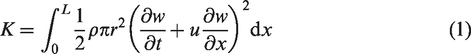
The kinetic energy of the moving jet is
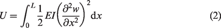
The bending energy of the jet can be written as
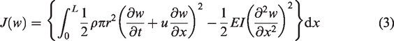
Ignoring the energy loss due to viscosity and air drag, we can establish a variational principle in the form
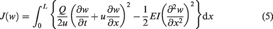
According to the mass conversation of the jet
1

The Euler–Lagrange form of equation (3) is
Assuming the jet’s motion is steady, we have

In order to elucidate the basic vibration property of the moving jet, we introduce a new variable


Integrating equation (9) twice and ignoring the integration constants, equation (9) becomes
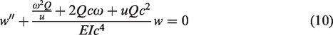
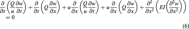
This equation has a frequency in the form
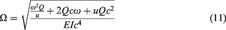
A higher frequency results in larger loss of the moving jet’s energy, and it will greatly affect the fiber’s morphology. In the multi-needle electrospinning, it is necessary to guarantee all jets have same ejecting velocity and same frequency, the former should be as large as possible, while the later should be as small as possible. To this end, we propose an auxiliary electrode to enhance the electric force on each nozzle, and design a uniform electric field in this paper.
Our previous study 31 also showed that more uniform electric field and larger electric field strength can be created by an auxiliary grounded electrode, which improved also the yield of nanofibers, and the results showed that the number of jets could be controlled by the position and diameter of the auxiliary electrode.
Electric field simulation for setup design
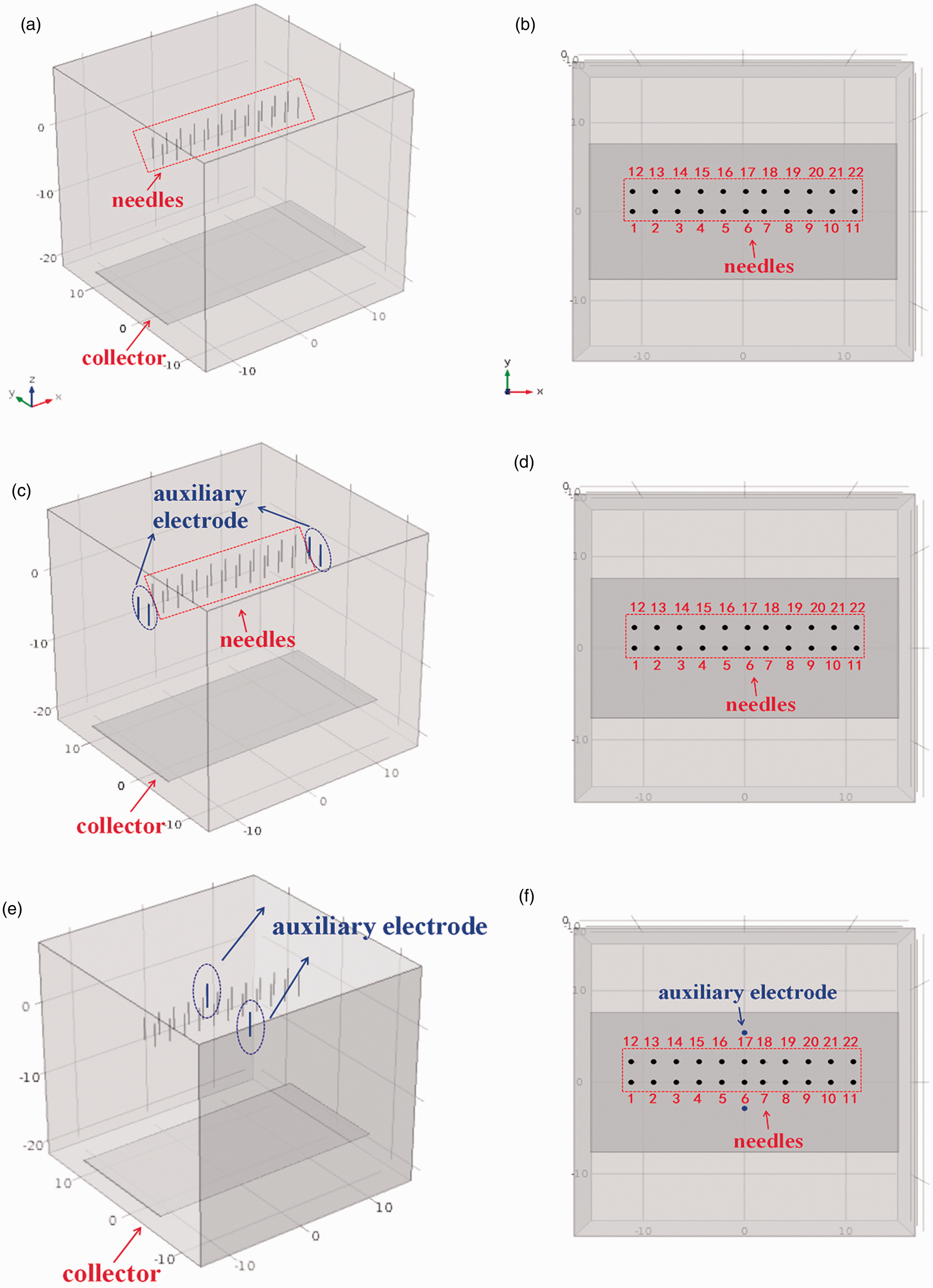
The electrospinning device consists of three parts: a high voltage electrostatic generator, a liquid supply device and a fiber receiving collector, as shown in Figure 1. During electrospinning, polymer solution is charged and deformed under high electric field. Then, under the driving force of electric field, polymer droplet is stretched from hemispheres to a cone at the end of capillary tube, that is, Taylor cone. When the electric field is large enough, the polymer droplet will overcome surface tension and the jet will be formed. 32 The jet liquid, being charged, will lead to the jet whipping, and during this time, the diameter of the jet will decrease in its bending state. 33 The jet will be deposited in the receiving collector after high speed stretching in the electric field, solvent evaporation and curing, and finally, the polymer nanofibers will be formed.
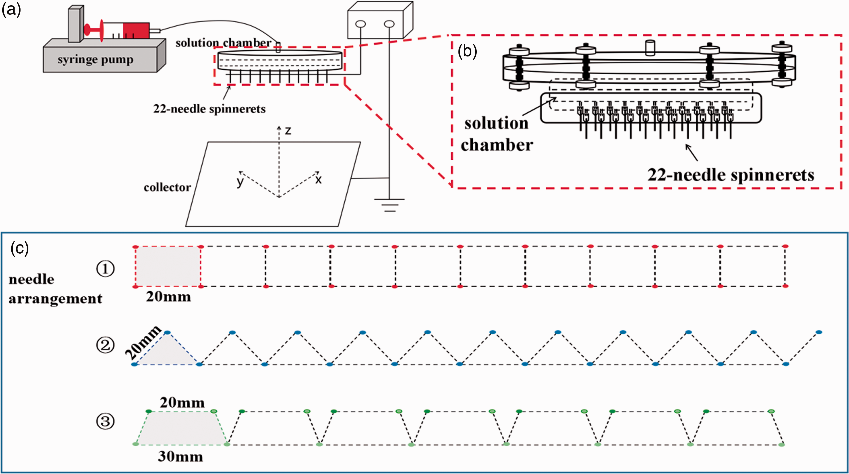
(a) The schematic illustration of the electrospinning setup. Needle distribution cells: (b) partial enlargement image of needle spinneret; (c) three needle arrangements.
Electric field plays an important role in producing required jet vibration in electrospinning. Software COMSOL Multiphysics 5.0 provides a numerical technique to simulate the electric field using the finite element method (FEM). The electric field strength and distribution can be calculated using the COMSOL with the practical dimensions of the electrospinning setup. Electric field simulation is adopted to design a suitable electrospinning configuration with a more uniform electric field distribution for the multi-needle electrospinning system, several designed configurations with various spinneret geometries were simulated by COMSOL Multiphysics 5.0 software. In all simulation works, a voltage of 15 kV was set to the spinneret, and the collector and the boundaries at an infinite distance were set as zero potential. The distance between the spinneret tip and collector was set to 15 cm in all the simulations.
Spinneret design
In this study, 22-needle spinnerets with and without auxiliary electrode were investigated. Figure 1 shows the 22-needle electrospinning without auxiliary electrode. Three kinds of multi-needle electrospinning configuration with the same needle number (22) (Figure 1(b) to (d)) were designed to examine the effect of spinneret geometry and auxiliary electrode on electric field distribution. The collector used was a flat target with 300 mm long, 150 mm wide and 1 mm thickness. Position 1 is 22-needle spinnerets at square array with 20 mm length of side (Figure 1(b)). Position 2 is 22-needle spinnerets at isosceles triangle array and the base and height of the triangle are all 20 mm (Figure 1(c)). Position 3 is 22-needle spinnerets at isosceles trapezoid array, upper and lower base are 20 mm and 30mm, respectively, and height is 20 mm (Figure 1(d)).
Multi-needle spinneret with and without auxiliary electrode
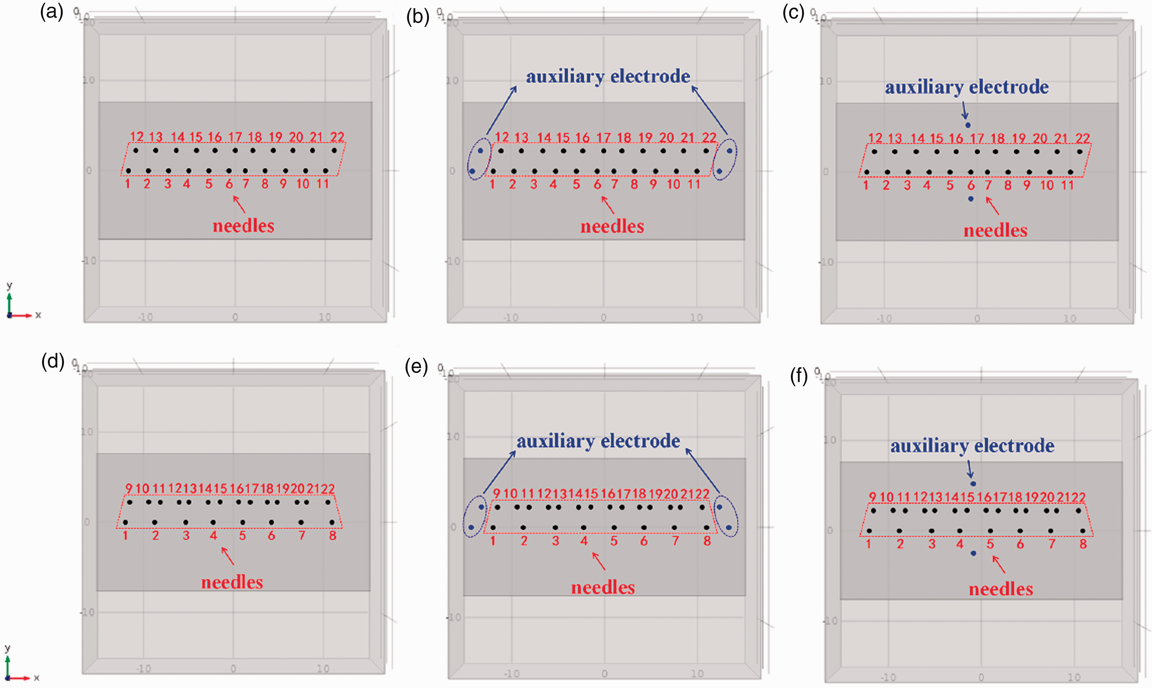
As shown in Figure 2(a) and (b), 22 metal needles were distributed in a square configuration (position 1) without auxiliary electrode (system 1). The spacing between neighboring needles was 20 mm. Twenty-two-needle spinneret with four auxiliary electrodes at broadside position is shown in Figure 2(c) and (d), it concludes auxiliary electrode with positive voltage (system 2), which is the same as spinneret, and auxiliary electrode is grounded (system 3). Figure 2(e) and (f) shows 22-needle spinnerets with two auxiliary electrodes at middle position, it is similar to the previous device, auxiliary electrode with positive voltage (system 4), which is the same as spinneret, and auxiliary electrode grounded (system 5) were used.
Twenty-two-needle spinnerets at square array without auxiliary electrode: (a) 3D illustration; (b) 2D needle distributions in the x–y plane. Twenty-two-needle spinnerets at square array (with four auxiliary electrodes at broadside position): (c) 3D illustration; (d) 2D needle distributions in the x–y plane. Twenty-two-needle spinnerets at square array (with two auxiliary electrodes at middle position): (e) 3D illustration; (f) 2D needle distributions in the x–y plane.
Twenty-two-needle spinnerets at isosceles triangle array (position 2) and at isosceles trapezoid array (position 3) are shown in Figure 3(a) to (c) and (d) to (f), respectively. The spacing between neighboring needles along the same y-axis was 20 mm of position 2. In position 3, the spacing between neighboring needles along the upper y-axis was 20 mm and the lower y-axis was 30 mm. Electric field distribution of position 2 and position 3 under different five systems are all simulated.
2D needle distributions in the x–y plane of 22-needle spinneret at isosceles triangle array: (a) without auxiliary electrode; (b) with four auxiliary electrodes at broadside position; (c) with two auxiliary electrodes at middle position. 2D needle distributions in the x–y plane of 22-needle spinneret at isosceles trapezoid array: (d) without auxiliary electrode; (e) with four auxiliary electrodes at broadside position; (f) with two auxiliary electrodes at middle position.
Results and discussion
The simulation of 22-needle spinnerets at square configuration (position 1) under systems 1–5 was studied, as shown in Figure 4. It shows the distribution of the electric field of this multi-needle electrospinning in the 3D plane is calculated by the software COMSOL Multiphysics 5. It can be seen that the electric field distribution of system 1 (Figure 4(a)), system 2 (Figure 4(b)) and system 5 (Figure 4(e)) is inhomogeneous and asymmetrical, unlike the symmetrical distribution in system 3 (Figure 4(c)) and system 4 (Figure 4(d)). The red area around the spinneret illustrates the strongest electric field.
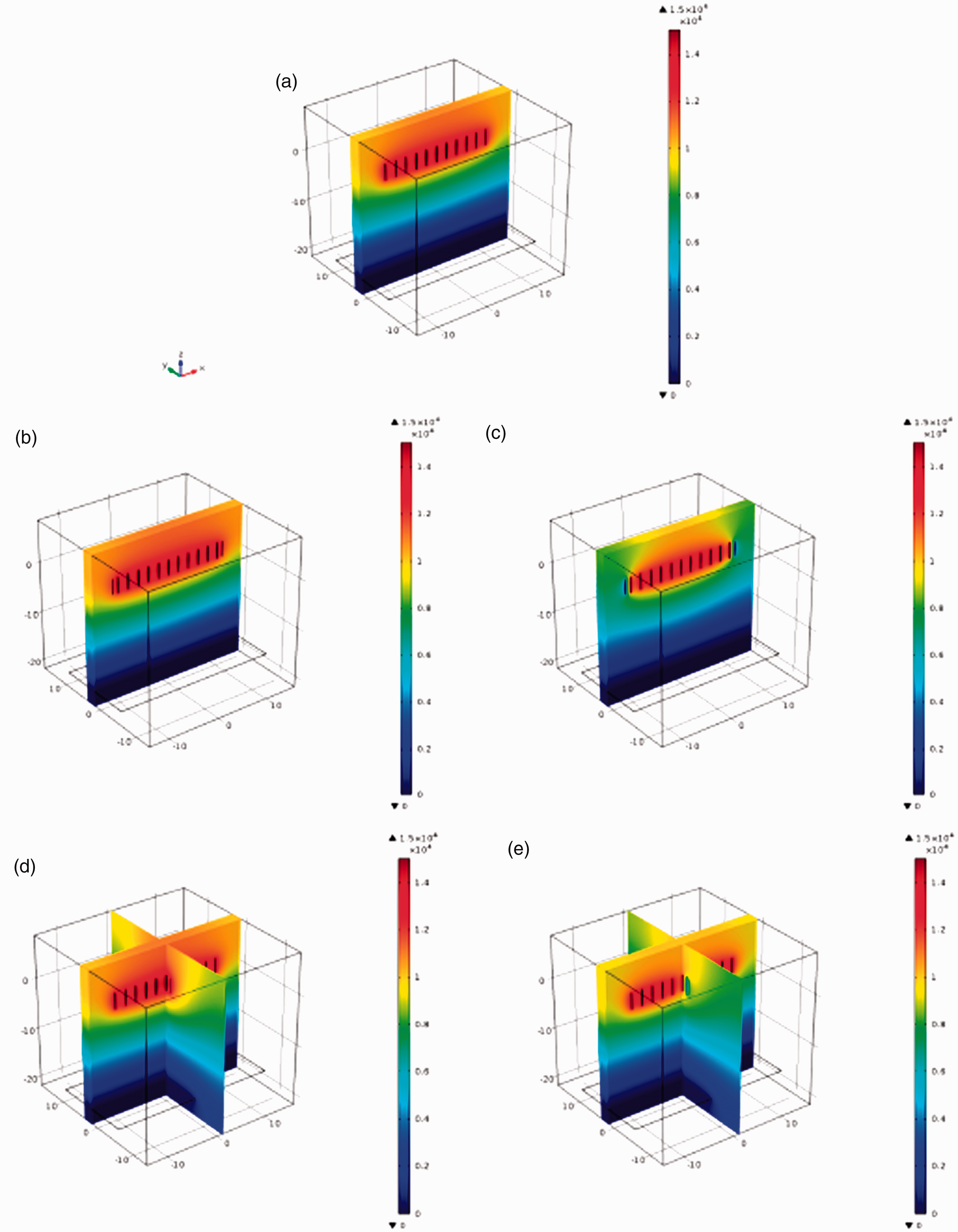
Simulation of electric field distribution on needle square configuration (position 1), auxiliary electrode at the height of 15 cm: (a) without auxiliary electrode (system 1); four auxiliary electrodes at broadside position: (b) with positive voltage (system 2); (c) auxiliary electrode is grounded (system 3); two auxiliary electrodes at middle position: (d) auxiliary electrode with positive voltage (system 4); (e) auxiliary electrode is grounded (system 5).
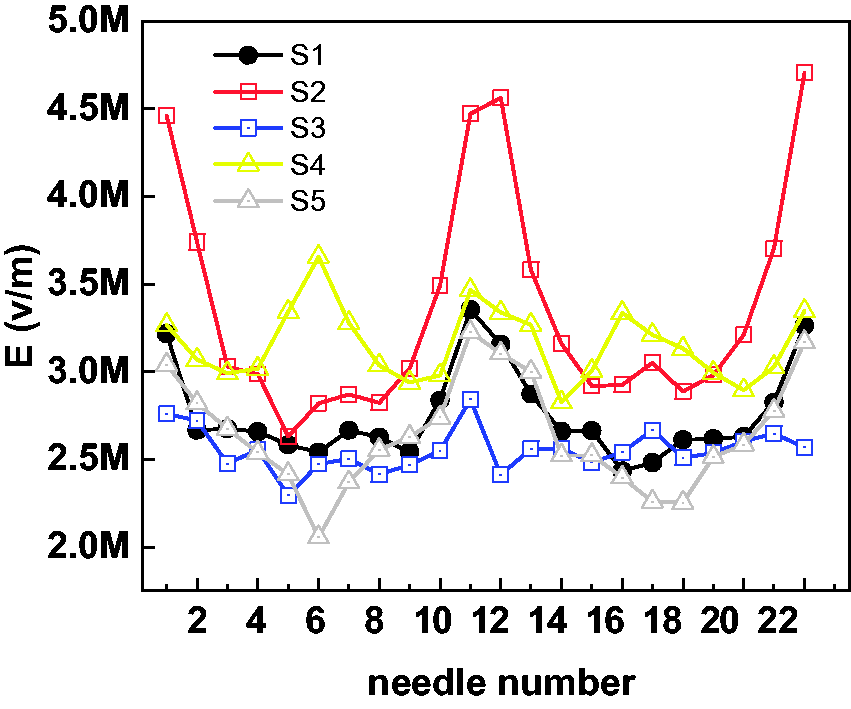
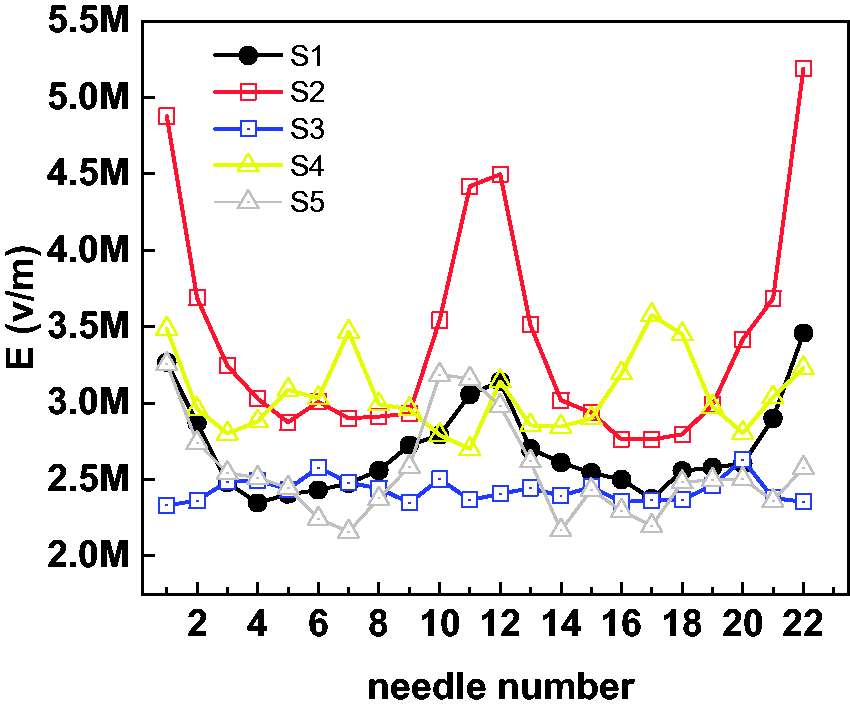
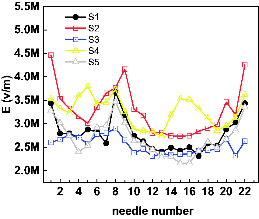
Graphs of electric field strength in needle position 1 versus needle number from the spinneret tip along z-axis.
The simulation electric field strengths for the needle position 1 under five different systems near the tips of the needles and the auxiliary electrode 150 mm above the collector are shown in Figure 4(a) and Table 1. As shown in Figure 5, the results show that electric field strengths of outside needles are larger than that of inside needles, which make electric field nonuniform leading to dripping or non-working needles during the electrospinning process when position 1 with system 1, when electrospinning with the auxiliary electrode at position 1, systems 3 and 5 produced smaller electric field strength than that of system 1, while systems 3 and 4 produced larger electric field strength than that of system 1. It can be seen that the introduction of the auxiliary electrode with positive voltage weakened the electric field strength at the spinneret tip and auxiliary electrode is grounded and it enhanced the electric field strength at the spinneret tip.
Calculated standard deviation of electric field strength around spinneret tip for the 22-needle spinneret at square array (position 1). All needle tips were 15 cm above the collector. Electrode tips were 14, 15 and 16 cm above the collector. Applied voltage: 15 kV.
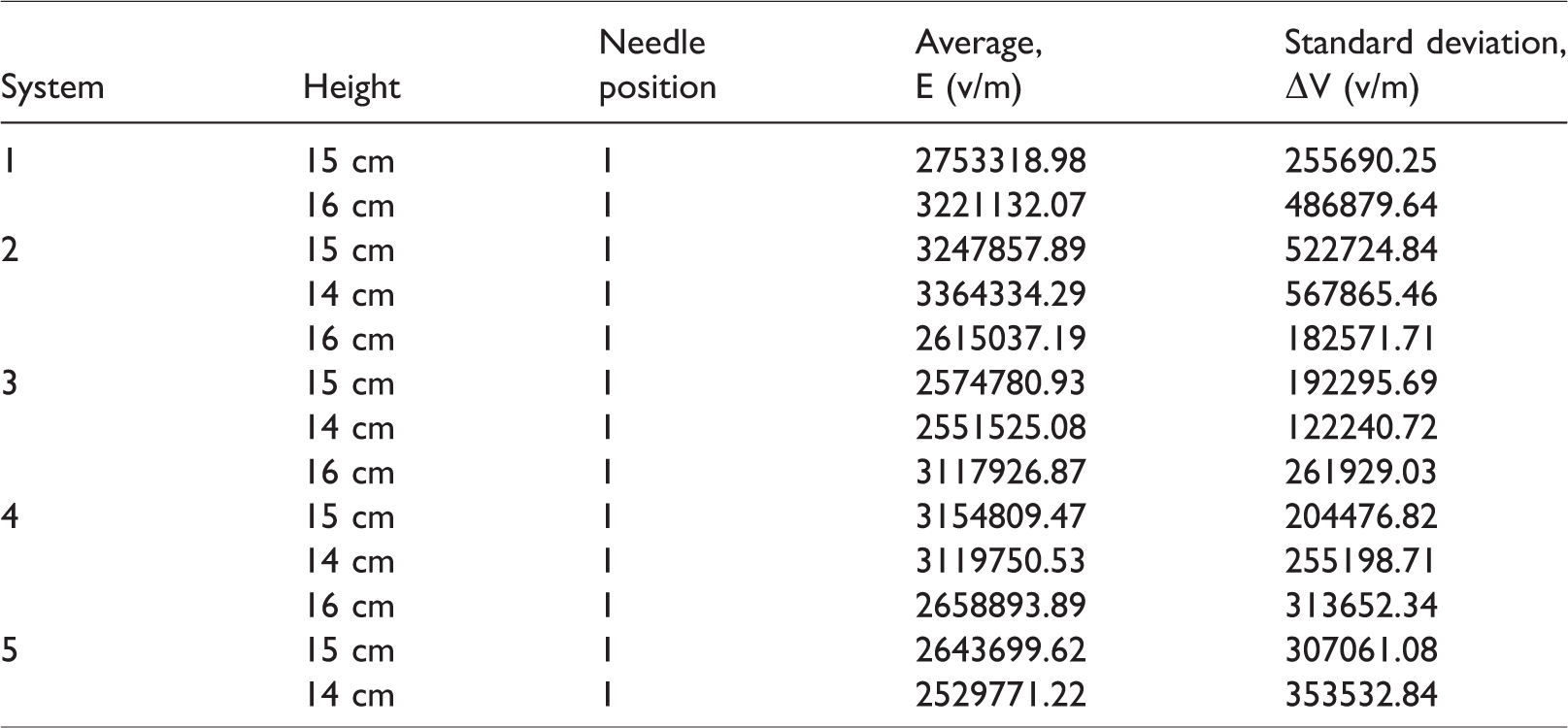
Three different auxiliary electrode positions (height of 14, 15 and 16 cm) in the 22-needle system of position 1 under five systems were chosen to be simulated (Table 1). The electric fields of the spinneret with various auxiliary electrode position were calculated in order to study the effect of the electrode position on electric field distribution. The average electric field strength of Needle position 1 is calculated by

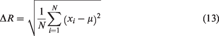
It can be seen that the average electric field strength of system 1 is 2786817.76 V/m, the largest average electric field strength is 3364334.29 V/m in system 2 with auxiliary electrode height of 14 cm and the smallest average electric field strength is 2529771.21 V/m in system 5 with auxiliary electrode height of 14 cm. Uniformity of the electric field is vital to the multi-needle electrospinning for producing fine nanofibers, based on equation (1), then we calculated the standard deviation (ΔR) between each adjacent pair of needles:
The simulation results are shown in Table 2 that the ΔE of 22-needle spinnerets electrospinning of position 1 in system 1 is 255690.25 V/m. When needle position 1 with auxiliary electrode is grounded (systems 3 and 5) under three different auxiliary electrode positions, the ΔE was larger than ΔE of position 1 needles without auxiliary electrode (system 1). The ΔE of systems 3 and 4 was smaller than ΔE of system 1. The smallest standard deviation ΔE between the needles position 1 is 122240.72 V/m of system 2 at the electrode tips 140 mm above the grounded target. The ΔE of system 4 at the electrode tips 150 mm above the grounded target is 204476.82 V/m, which is the second smallest among five systems. This means that four broadside auxiliary electrodes with positive voltage (system 3) and two middle grounded auxiliary electrodes (system 5) can make the electric field at the inside tips more uniform. More uniform electric field distribution can help to produce finer and more uniform fibers. 34
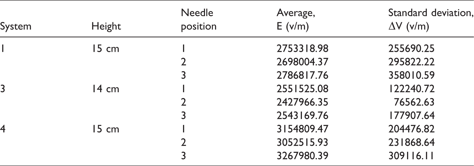
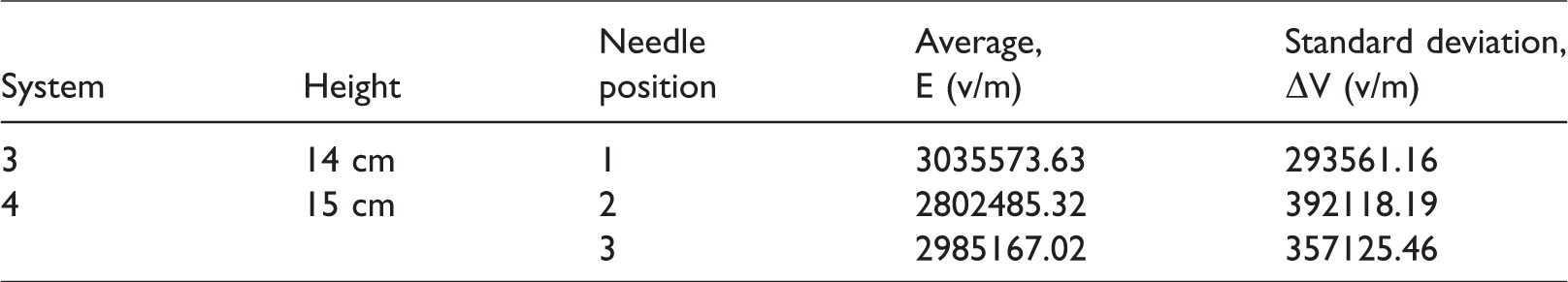
Calculated standard deviation of electric field strength around spinneret tip for the 22-needle spinneret at positions 1, 2 and 3. All needle tips were 15 cm above the collector. Systems 3 and 4 electrode tips were 14 and 15 cm above the collector, respectively. Applied voltage: 15 kV.
The calculated electric field strength of the 22-needle spinnerets at isosceles triangle array configuration (position 2) (auxiliary electrode along the z-axis at 150 mm above the collector) is shown in Figure 6. The results show that electric field strengths of outside needles are larger than that of inside needles when position 2 with system 1. Systems 3 and 5 produced smaller electric field strength than that of system 1, while systems 3 and 4 produced larger electric field strength than that of system 1 when electrospinning at needle position 2. As shown in Figure 7, electric field strength of the 22-needle spinnerets at isosceles trapezoid array configuration (position 2) (auxiliary electrode along the z-axis at 150 mm above the collector) was simulated. It can be seen that the introduction of the auxiliary electrode with positive voltage weakened the electric field strength around the spinneret tip and auxiliary electrode with ground enhanced the electric field strength around the spinneret tip. Similar tendency was found in position 1 compared to these two needle position configurations.
Graphs of electric field strength in needle position 2 versus needle number from the spinneret tip along z-axis.
Graphs of electric field strength in needle position 3 versus needle number from the spinneret tip along z-axis.
Based on the simulation results of the 22-needle spinnerets at position 1 with and without auxiliary electrode electrospinning system and the discussion above, system 3 was found to create a more uniform electric field and smaller electric field strength and system 4 to create a more uniform electric field and larger electric field than that of system 1. Additionally, system 3 (auxiliary electrode with height of 14 cm) and system 4 (auxiliary electrode with height of 15 cm) were used as a method to get a relatively more uniform and at the same time more focused electric field. We simulated positions 1, 2 and 3 under these two systems as shown in Table 2. Under system 1, position 1 produced the smallest average electric field strength E (=2698004.37 V/m) and standard deviation ΔE (=235682.25 V/m) among all needle positions. Under system 3, position 2 produced the smallest average E (=2427966.35 V/m) and ΔE (=76562.63 V/m) among the three needle positions, while under system 2, the position 2 produced the smallest average E (=3052515.93 V/m) and position 1 produced smallest ΔE (=204476.8245 V/m) among all needle positions.
To study the effect of the auxiliary electrode on electrospinning electric field, system 3 at auxiliary electrode height of 14 cm and system 4 at auxiliary electrode height of 15 cm were proved that they can enhance uniformity of electric field. However, system 3 creates a smaller electric field strength and system 4 creates a larger electric field than that of system 1. Therefore, we simulated 22-needle spinneret electrospinning with system 3 at auxiliary electrode height of 14 cm and system 4 at auxiliary electrode with height of 15 cm at the same time. As shown in Figure 8 and listed in Table 3, it was clear that the new design did not achieve the desired results. The ΔE of positions 1, 2 and 3 needles was larger than only system 3 or 4. It has been found that the introduction of auxiliary electrode can change the uniformity of electric field distribution, and we can design the electric field distribution by change position of auxiliary electrode. It provides a new perspective to design multi-needle electrospinning configuration and has potential to produce thinner fibers and more concentrated collection mats at a high production rate.
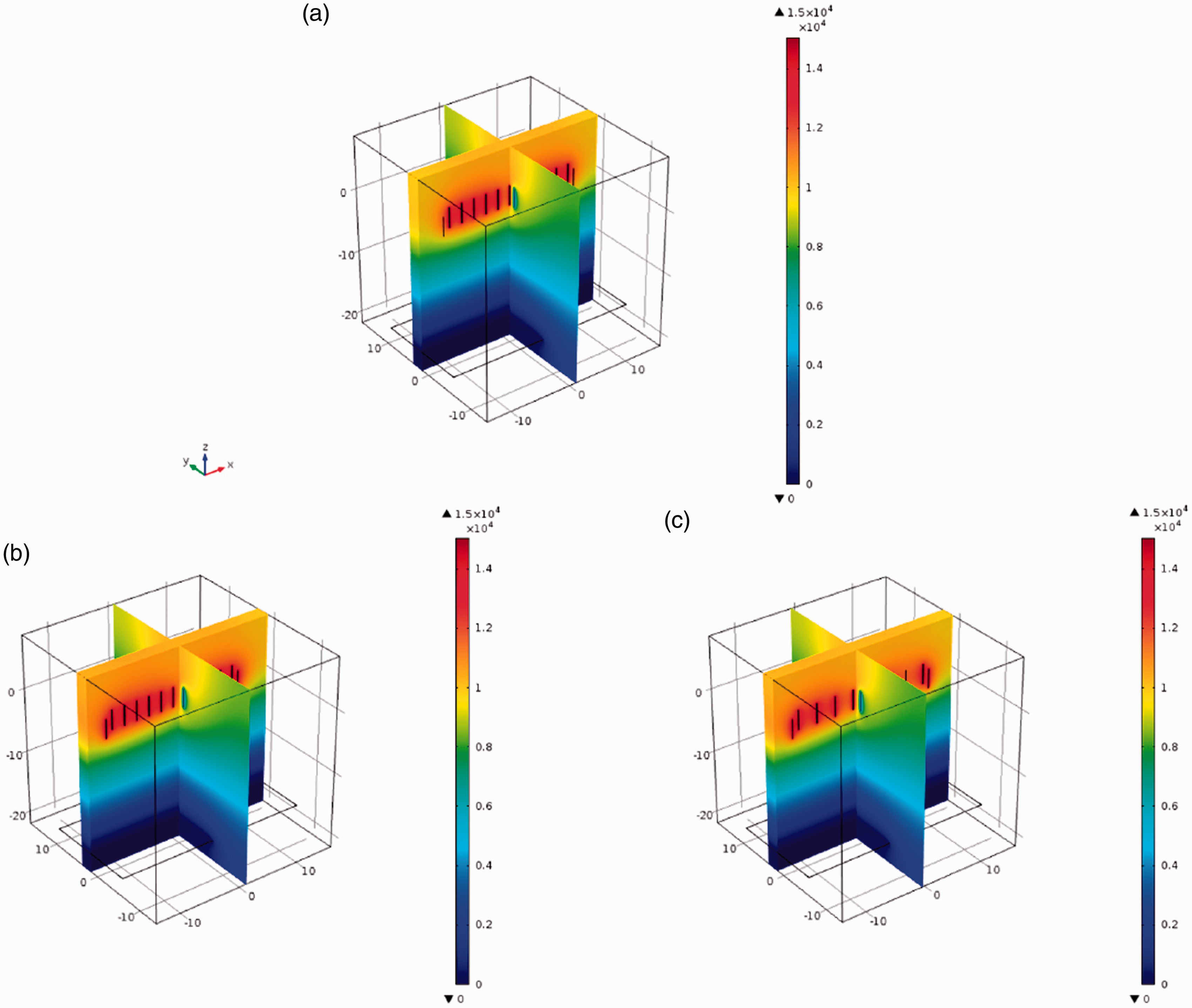
Simulation of electric field distribution on system 3 at auxiliary electrode height of 14 cm and system 4 at auxiliary electrode height of 15 cm: (a) needle position 1; (b) needle position 2; (c) needle position 3.
Calculated standard deviation of electric field strength around spinneret tip for the 22-needle spinneret at positions 1, 2 and 3. All needle tips were 15 cm above the collector. Systems 3 and 4 electrode tips were 14 and 15 cm above the collector at the same time. Applied voltage: 15 kV.
Conclusion
In this work, multi-needle electrospinning spinnerets, whose needles arranged in different geometric distributions with auxiliary electrode, were designed to investigate the auxiliary influence of electrode and needles geometric distributions on electric field distributions and jet vibration. The electric field distributions of these spinnerets were simulated by Software COMSOL Multiphysics 5.0 using FEM. The simulation results indicated that multi-needle electrospinning spinnerets with four broadside auxiliary electrodes of positive voltage (system 3) and two middle auxiliary electrodes of ground (system 4) created more uniform electric field distribution compared with other spinnerets without auxiliary electrode (system 1), even though system 3 receded the electric field of periphery needles and system 4 reinforced the electric field of central region needles. That is to say, the multi-needle electrospinning spinneret with auxiliary electrode at broadside (with voltage) and at middle position (with ground) is conducive to create uniform and steady jets vibration and electric field distribution. This research is significant for scaling up the production of multi-needle electrospinning in theory and industry. The present theory and results are also valid for the macromolecular electrospinning,35–37 which was the last development of electrospinning and the spinning process can be controlled on a molecular scale.
Footnotes
Declaration of conflicting interests
The author(s) declared no potential conflicts of interest with respect to the research, authorship, and/or publication of this article.
Funding
The author(s) disclosed receipt of the following financial support for the research, authorship, and/or publication of this article: This work was supported by National Natural Science Foundation of China (No. 51573133), the Science and Technology Plans of Tianjin (No. 15PTSYJC00230), the China Postdoctoral Science Foundation Grant (Grant No. 2018M630949), the Central University Scientific Research Project (Grant No. 2017BQ051), Natural Science Foundation of Guangdong Province China (Grant No. 2018A0303100022), Dongguan Social Science and Technology Development Project (Grant No. 20185071631280).