
Abstract
Usually cars are equipped with disk horns. In these devices electromagnetic energy is converted into mechanical energy of two nuclei that vibrate and impact each other – the impacts excite the disk that radiates sound. This paper aims at understanding the results of acoustic tests carried out on horns with different excitation voltages and different mounting brackets. Since many non-linear phenomena are inherent in the vibrations of the nuclei, a detailed model of the electromechanical system is developed. Results show the dependence of operating frequency on the input voltage and the role played by the various mechanical and electrical parameters on the dynamics of the horn. Particular non-linear effects, like sub-harmonic excitation, are presented and discussed. A general agreement between experimental results and numerical simulations is found.
Introduction
Every road vehicle is equipped with a horn, which plays an important role for the improvement of safety. Usually cars, vans and motorcycles are equipped with trumpet horns or disc horns, which are electromagnetically driven. Compressor-driven horns can be found in heavy road vehicles, trains and crafts. Nowadays, the car horn is a mass production component, which is manufactured in factories with a high automation level. The present car horn has evolved from the ancient musical horn and from the rubber pear horns of old fashion cars essentially by means of a trial-and-error approach. The result is a compact, efficient and sturdy device, which can withstand harsh weather conditions.
In the past, very few researches have been carried out on horns. In recent years, the scientific interest in car horns is growing due to the increased sensitivity of people and institutions to noise pollution, the availability of cheap and efficient electronic devices and the widespread use of electric vehicles.
The car horn, in order to accomplish its task, has to generate high levels of sound pressure, which are required by specific norms, 1 but in many circumstances drivers make a misuse of horns generating noise pollution. 2 Recent studies 3 have shown that often horns are used not only to gain attention and inform of danger (correct use), but also to vent anger or to express gratitude. In order to decrease noise pollution, sound management strategies for car horns have been proposed 1 ; they aim at reducing the sound level generated by the horn in silent areas and when the speed is very low, because in both cases a reduced sound level is enough to gain attention of drivers and pedestrians letting a sufficient reaction time. The implementation of sound management strategies requires electronic controllers and sensors. Nowadays, the quick development of microprocessors and sensors makes these technologies rather cheap and suited to implementation in low-cost devices (like a car horn).
Electric and hybrid electric vehicles in the near future will give an important contribution to the reduction of pollution and noise in urban environment,4,5 but these vehicles are very quiet (especially at low speed) and this feature may be an hazard for pedestrians and cyclists, who are used to detect the presence of approaching cars according to the noise they generate. This hazard is even greater for pedestrians with impaired sight and hearing. For these reasons, some researches6,7 have been carried out on warning sounds for electrical and hybrid vehicles. These sounds can be generated by loudspeakers and by new electromagnetic horns.
The electromagnetic horn is a multi-physics system, since it consists of many components governed by different physical laws that interact in order to generate the desired effect. There is a mechanical vibrating system composed of a mass (the mobile nucleus) mounted on a flexible membrane. There is an electromagnetic system composed of a coil and a fixed nucleus, which is used for exciting the vibrating system. The vibrating system and the electromagnetic system are the motor of the horn and they interact through a circuit breaker, which is actuated by the motion of the mobile nucleus. Finally, there is an acoustic system which aims at transforming the mechanical energy of vibrations into acoustic energy. This system may have two different layouts. In the first layout, the acoustic system is composed of a flexible membrane, a compression chamber and a snail horn; in this case, sound is radiated by the flexible membrane and amplified by the snail horn. In the second layout, the mobile nucleus is equipped with a metallic disk; when the mobile nucleus impacts the fixed nucleus the disk is excited by a periodic force, vibrates and radiates sound. Most of the recent studies on car horns have focused on the acoustic system. Psycho-acoustical methods were adopted to study the timbre and the quality of sound generated by horns 8 . In Bonfiglio and Pompoli 9 a finite element method was adopted to optimize the geometry of the snail horn, in order to increase emitted sound pressure. The quality of sound generated not only outside the vehicle, but also inside was studied in Kang et al. 10 and an optimal horn was designed by means of transfer path analysis and boundary element analysis.
The understanding of the phenomena deriving from the interaction between the vibrating system and the electromagnetic field is useful for designing new efficient horns. Therefore, the present paper focuses on the electromechanical system, which is a non-linear system that is described by non-linear differential equations. 11 A disk horn manufactured by FIAMM is considered and the effect of the mechanical characteristics of the mounting bracket is taken into account. It is worth noticing that the important effect of the mounting bracket has been highlighted in Kang et al. 10 as well. The paper is organized as follows. In the next section, the functioning principle is described and discussed making use of a simplified mathematical model. ‘Experimental results’ section deals with experimental test. The results of acoustic tests carried out in an anechoic room are presented and the effect of input voltage on sound frequency and spectrum is discussed. Then the dynamic properties of brackets are studied with the modal analysis approach. In ‘Mathematical model’ section, a multi-physics mathematical model of the horn is presented; it takes into account some non-linear effects both in the electrical domain (e.g. electric arc) and in the mechanical domain (e.g. non-linear stiffness of the membrane). This model is implemented in a Simulink code. In ‘Numerical results’ section, numerical results are presented and compared with experimental results. Finally, in the last section conclusions are drawn.
Functioning principle
The scheme of a typical disk horn manufactured by FIAMM is presented in Figure 1. The mobile nucleus, which is a rigid body with mass m, is connected to the case of the horn by means of the membrane having stiffness km, damping cm and negligible mass. The body of the harvester includes the coil, the coil nucleus and the case, and these components are assumed to be a unique rigid body having mass M. The body of the horn is connected to the vehicle by means of the bracket having stiffness kb and damping cb. The air gap between the two nuclei is
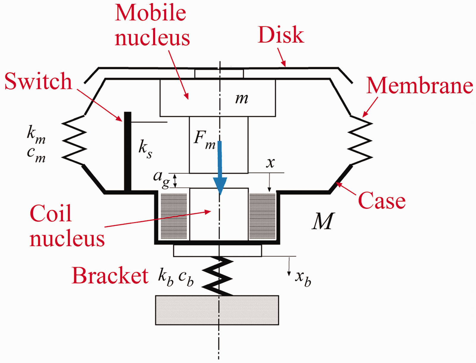
Scheme of a disk horn.
The equation of motion of the mobile nucleus is
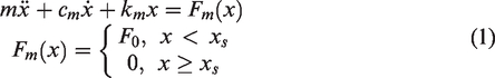
In which xs is the value of displacement x that switches off the circuit. For x < xs, the motion is forced by a constant force F0, for x ≥ xs the motion is free.
Equation (1) can be integrated numerically introducing state variables
Curves of the simplified model in the phase plane.
The semi-period of the resultant motion can be calculated considering that for x = xs the velocity of the forced motion must be equal to the velocity of the free motion (
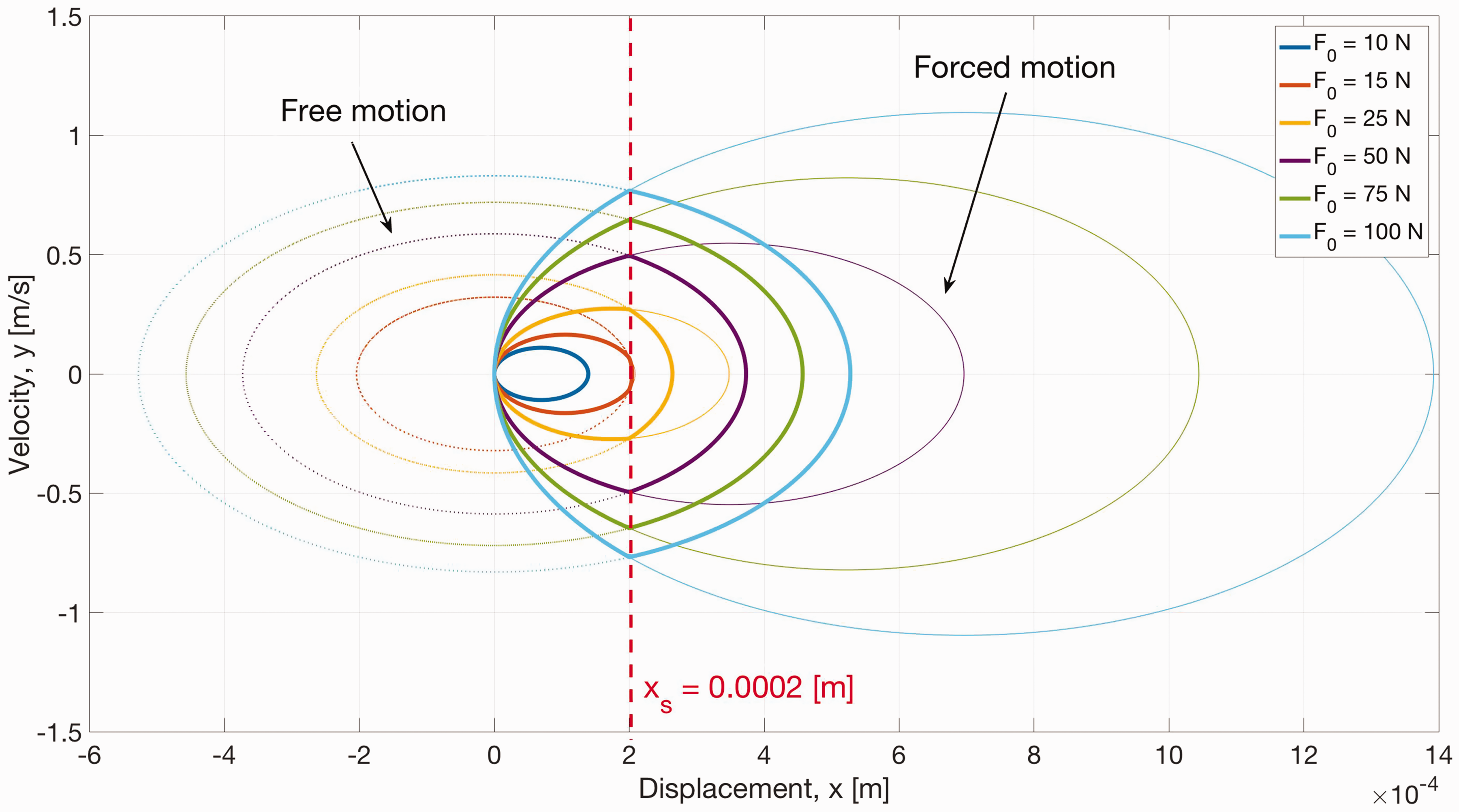
The results, which are presented in Figure 3, show that the frequency of oscillation is equal to the natural frequency of the system (
Dependence of vibration frequency on force amplitude.
Experimental results
The sound of the car horn is influenced by the connection between the horn and the car. 10 This connection is made by means of a bracket that is customized for each type of car. The customization of the bracket is mainly due to the different mounting positions and to the different installation volumes available in the vehicles.
In this research two brackets were considered (see Figure 4). The standard bracket is a cantilever beam with the horn fixed at the free end. The bridge bracket is a beam clamped at both ends with the horn mounted near the centre point.
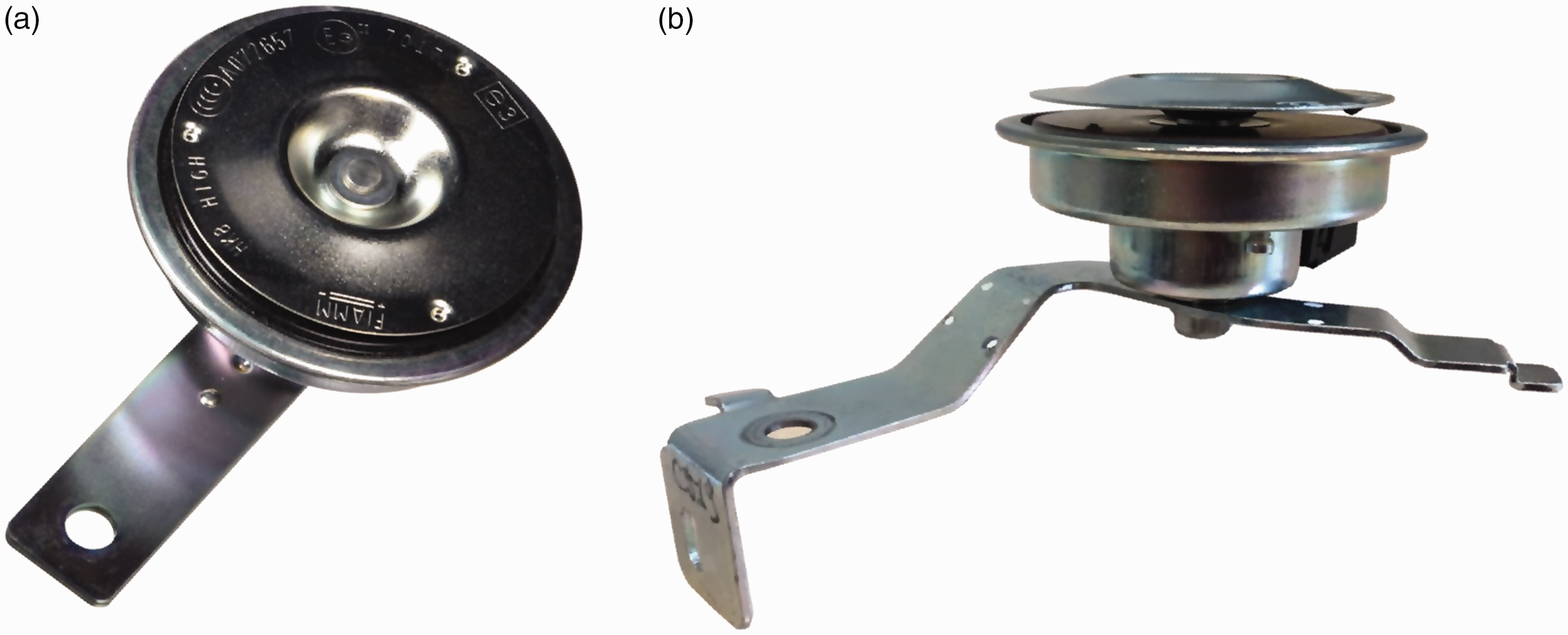
The tested horn on the standard bracket (a) and on the bridge bracket (b).
In this section the acoustic tests performed to identify the influence of the brackets on sound generated by the horn are described. Acoustics measurements were performed in an anechoic chamber according to the European Standard for measurements of acoustics parameters of audible warning device E/ECE/324/Rev.1. 12
The horn–bracket system was mounted on a rigid column and the sound was measured by a microphone aligned with the horn and positioned at a distance of 2 m (see Figure 5). The measurements were carried out by changing the input voltage from 14 to 8 V with a step of 0.5 V for each bracket. The measured sound was processed with the FFT algorithm 13 to calculate the sound spectrum in the frequency domain. The sound generated by a disk horn consists of a fundamental frequency and its harmonic components; the highest sound level is reached at a frequency close to the disk resonance. Figure 6 shows the spectra of the measured sound in a frequency range from 150 to 400 Hz. In this interval there is the fundamental harmonic of the generated sound and its frequency corresponds to the vibration frequency of the two nuclei. The most important effect of the bridge bracket is the appearance of a sub-harmonic when the input voltage ranges between 11.5 and 9.5 V. The frequency of this sub-harmonic is half the one of the fundamental harmonic.
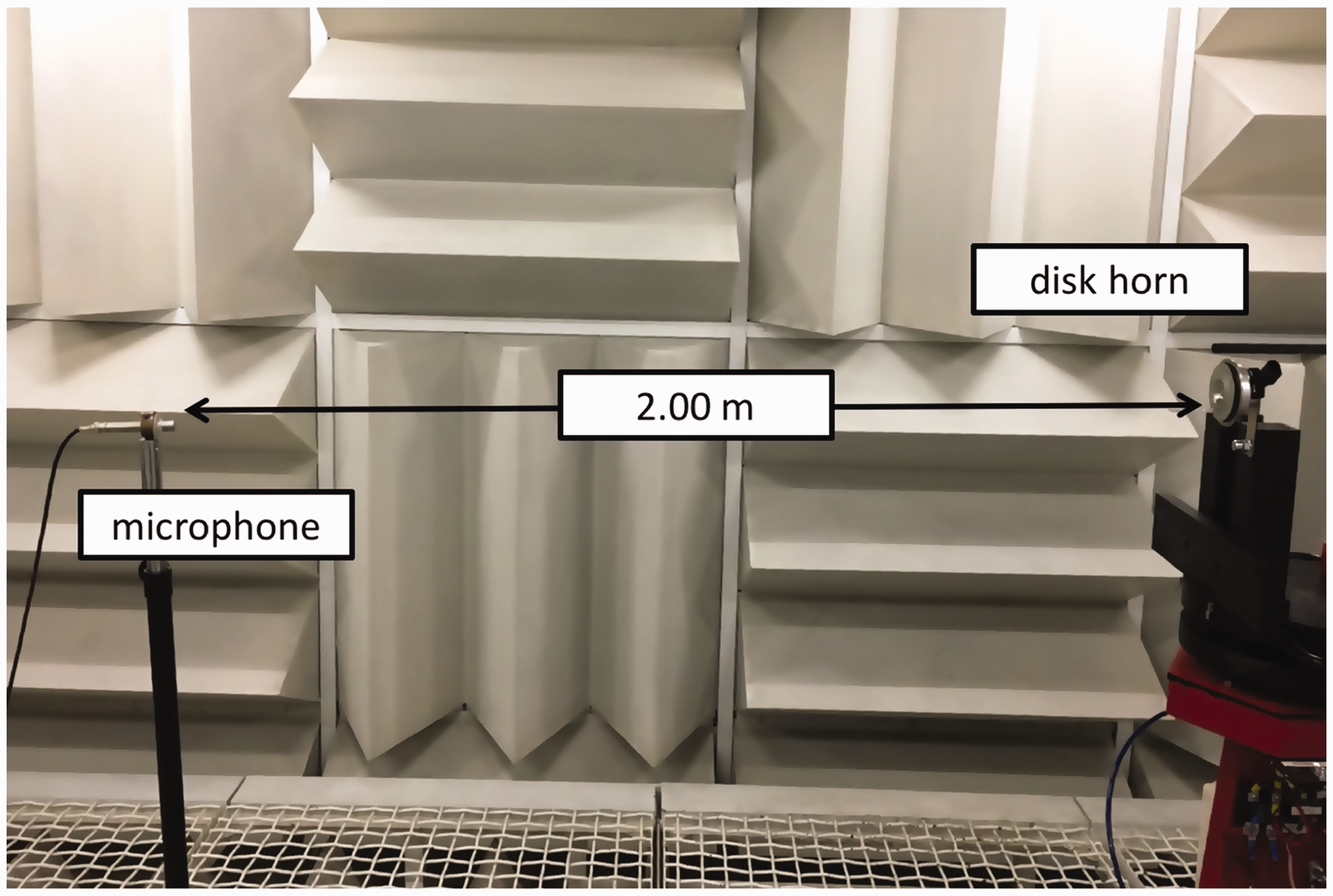
The measurement system: anechoic room with the horn.
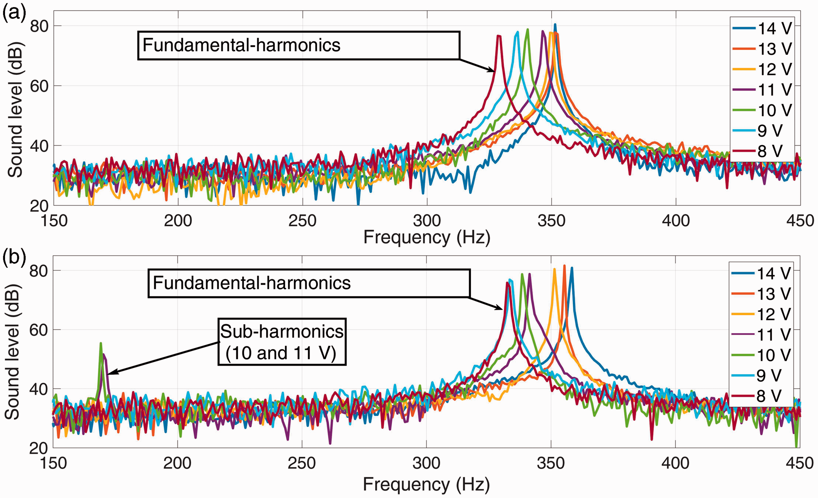
Sound spectra: (a) horn on standard bracket with the fundamental harmonics in the range 330–350 Hz and (b) horn on bridge bracket with fundamental harmonics and the sub-harmonics at about 175 Hz.
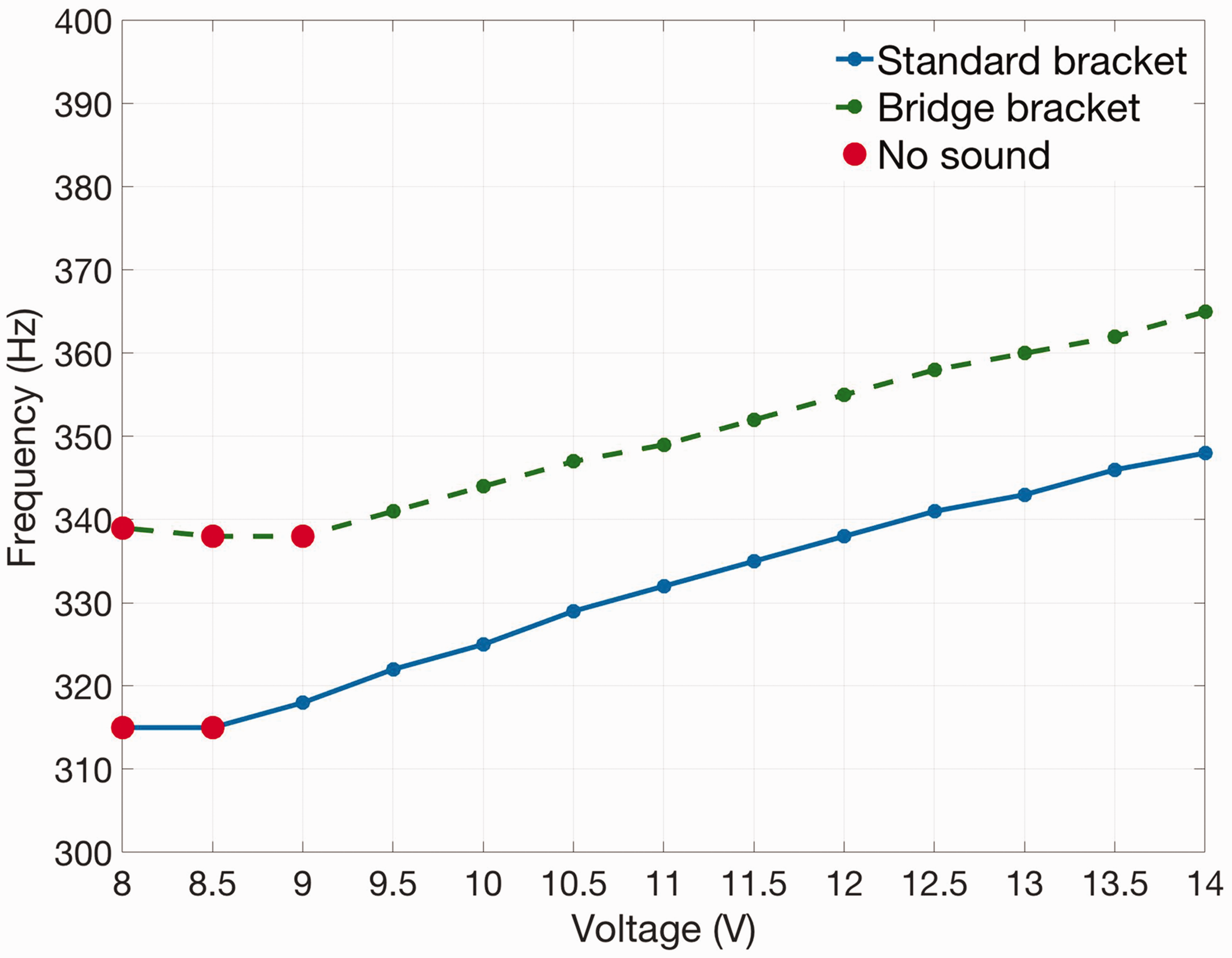
Figure 7 shows the trend of the fundamental frequency of the horn against the input voltage. With both brackets the fundamental frequency increases with input voltage. From 14 to 12 V the fundamental frequency of the horn on the bridge bracket is larger than the one of the horn on the standard bracket. For the horn on the bridge bracket, the sub-harmonic appears from 11.5 to 9.5 V and the fundamental frequency decreases.
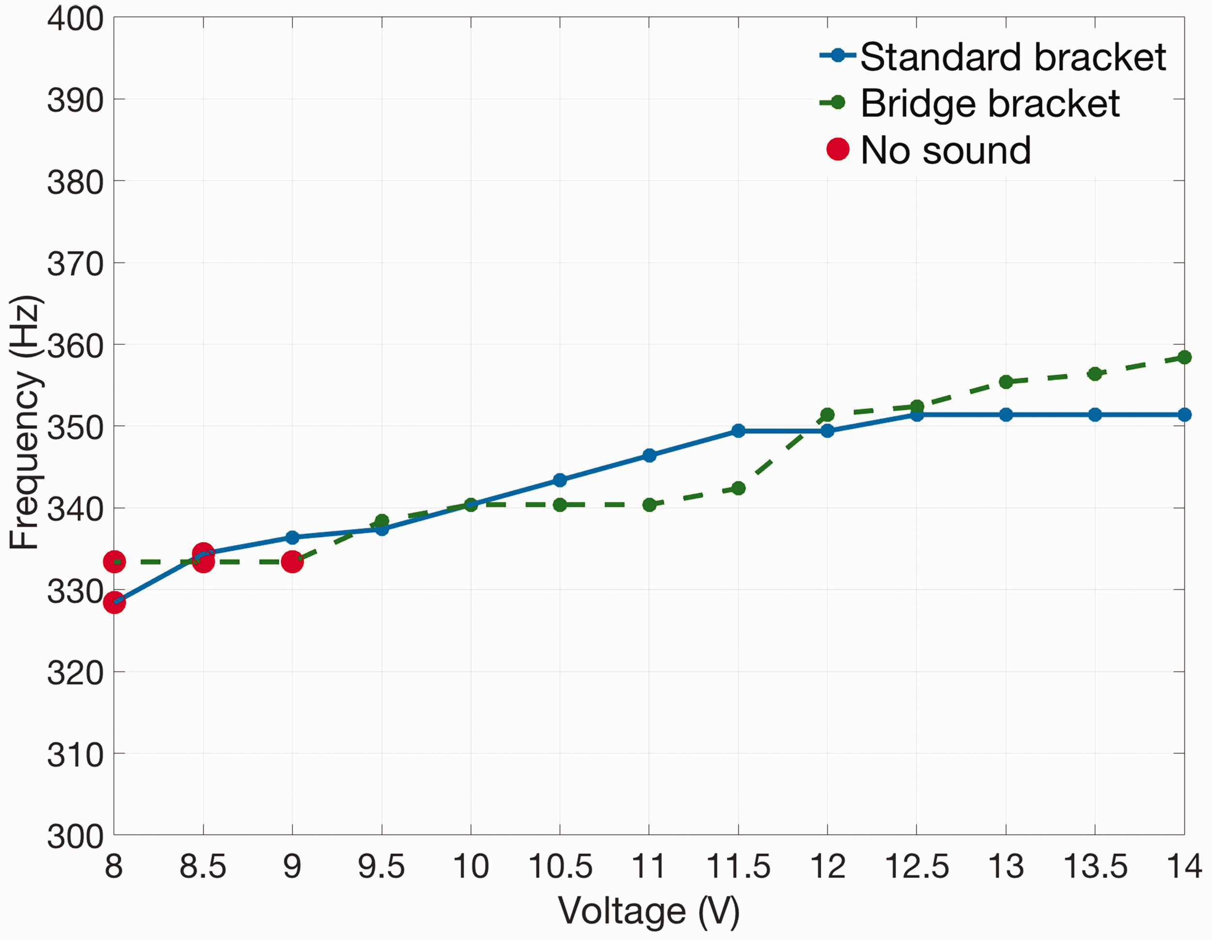
Dependence of vibration frequency on voltage, experimental results.
When the mobile nucleus does not impact the coil nucleus no sound is generated by the disk, this condition occurs at 9, 8.5 and 8 V with the bridge bracket and at 8.5 and 8 V with the standard bracket.
In order to understand the influence of the brackets on the dynamic behaviour of the horn, experimental tests were performed in the Modal Analysis Lab. of Padova University to identify the natural frequencies and the modes of vibration of the horn on the bracket.
These tests were carried out with the modal analysis technique, which is widely used in the field of aerospace 14 and automotive engineering. 15 This technique is based on the measurement of the frequency response functions (FRFs) between the accelerations of some points of the system and an exciting force having a wide frequency band (in order to excite all the relevant modes of vibration). In the framework of this research, an impulse excitation was applied by means of a small hammer, which guarantees a sufficient band of excitation and is compatible with the size of the system.
The test equipment included two small piezoelectric mono-axial accelerometers (mass 0.5 g). The first one was mounted above the mobile nucleus and the second one was positioned under the coil nucleus. The impulse was exerted on the mobile nucleus by means of a PCB 086E80 hammer for modal testing taking care to generate small amplitude vibrations to avoid entering in the non-linear field. The sensors were acquired by means of a NI 9234 board and signals were analysed in time and frequency domains by means of NI Signal Express.
Figure 8 shows the FRFs measured in two points, the direct FRF refers to a measurement point located very close to the excitation point. When the horn is mounted on the standard bracket two modes of vibration appear. In the first mode of vibration, with a frequency of 148.3 Hz, the two nuclei move in phase (see the phase plot of Figure 8(a)), whereas in the second and main mode at 368.4 Hz the two nuclei move in opposition. The natural frequency of the second mode is close to the operating frequency of the horn.
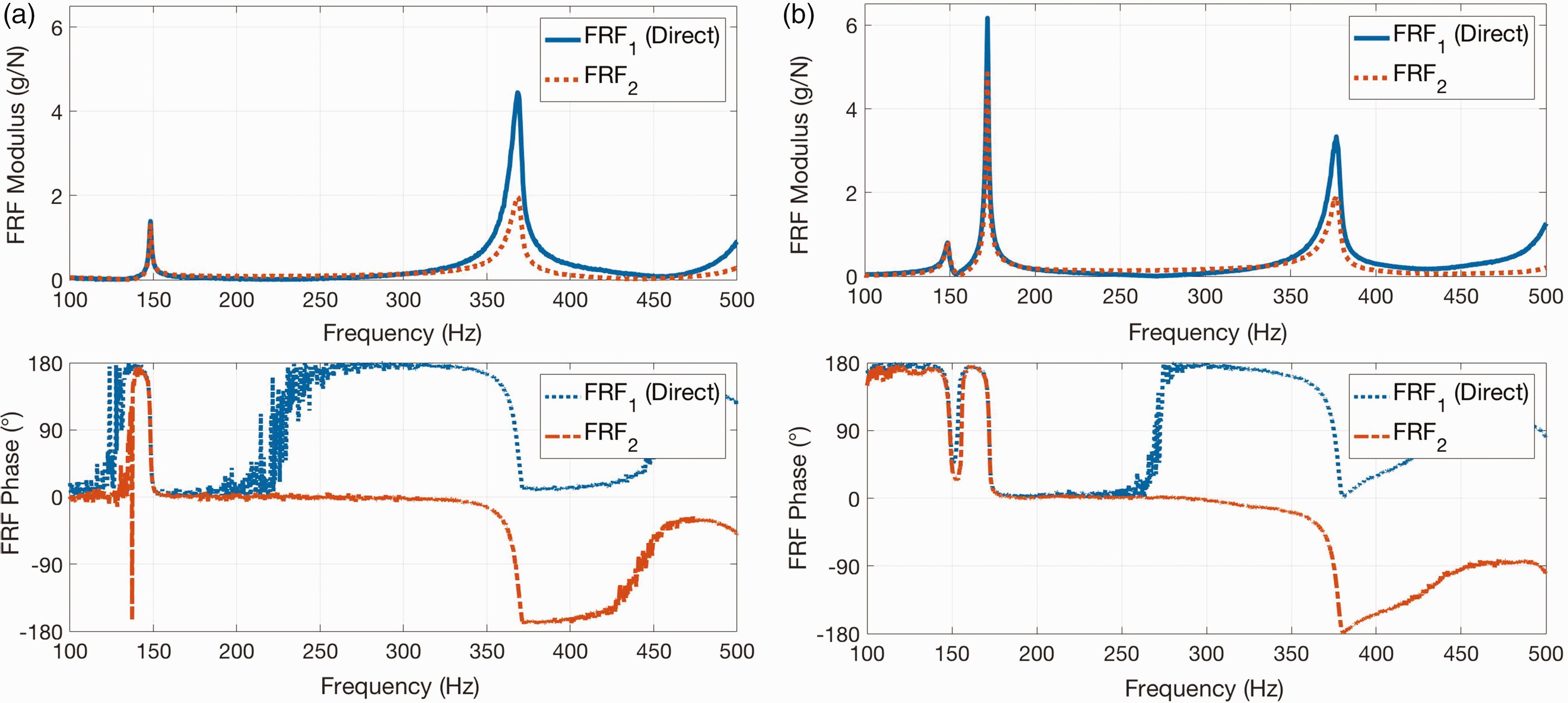
FRFs of the horn mounted on the standard bracket (a) and on the bridge bracket (b). FRF: frequency response function.
A similar behaviour appears when the horn is mounted on the bridge bracket. But in this case the in-phase mode (172.1 Hz) has larger amplitude than the in-opposition mode (376.9 Hz). Moreover, it is worth noticing that with the bridge bracket the frequency of the in-phase mode is higher and about half the one of the in-opposition mode.
Mathematical model
A lumped element multi-physical model of the horn is developed taking into account non-linear phenomena. The mathematical model is developed according to the scheme of Figure 1 and has two degrees of freedom. Disk dynamics are not taken into account, because a preliminary modal analysis of the disk showed that the first natural frequency is above 1000 Hz. This natural frequency may affect the acoustic performance of the system, but it has a negligible effect on the dynamics of nuclei.
The equations of motion of the mobile nucleus and of the body of the horn are


In these equations Fe is the elastic force of the membrane, Fm is the electromagnetic force exerted by the coil on the mobile nucleus, Pre is the preload force that is needed to open the switch and kc is the contact stiffness between the two nuclei. H is the Heaviside step function, which makes it possible to switch on the elastic forces that are present when the mobile nucleus touches the switch (x ≥ xs) and the coil nucleus (x ≥ xc). The expression of Fe is non-linear, since experimental tests show that membrane stiffness takes different values (
The electromagnetic force depends in non-linear way on x
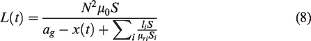
In equation (5) i is the current, N is the number of turns in the solenoid, S is the cross section area of nucleus and μ0 is the vacuum permeability. ageq is the equivalent air gap,
16
which takes into account that the magnetic circuit is partially in air (geometric air gap ag) and partially in iron
In the expression of equivalent air gap μri,
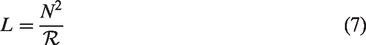
Figure 9 shows a scheme of the electric circuit of the horn, V is applied voltage, R is coil resistance and L(t) is coil inductance. Inductance L(t) can be expressed as a function of reluctance
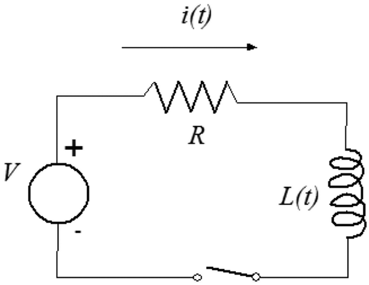
Electric circuit of the horn.
Reluctance
The application of Kirchhoff’s and Faraday–Neumann’s laws to the circuit of Figure 9 leads to the following equation

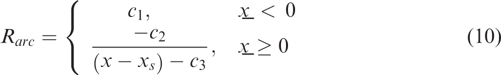
Equation (9) takes into account switching, which is a non-linear effect.
It is worth noticing that the relationship between input voltage
The system of differential equations composed of equations (2), (3) and (9) was implemented in Simulink and solved numerically.
Numerical results
The numerical model makes it possible to calculate the relevant electrical quantities (current, electromagnetic force) and the relevant mechanical quantities (displacements of nuclei, elastic and contact forces). Experimental tests include the acoustic measurements (described in ‘Experimental results’ section) and the measurement of current. The current in the horn circuit is tightly related to the switching phenomenon and to the dynamic behaviour of the motor, hence numerical values of current are compared with experimental values in order to evaluate the validity and accuracy of the numerical model.
Figure 10 shows (for three values of voltage) the comparison between measured and simulated currents when the horn is mounted on the standard bracket. There is a good agreement between the two sets of results both in terms of values and in terms of wave shape. The maximum difference between the peak values is less than 10%. The durations of the current impulses and the instants when the circuit opens (zero current) are almost equal; this means that the numerical model is able to represent the switching phenomenon. The calculated current in the switch-off phase is almost zero (like in experimental tests) and this is an effect of the simulated electric arc. The calculated current impulses have a round shape (like in experimental tests) and this is an effect of variable inductance. The increasing trend of the current with voltage, which is shown in Figure 10, corresponds to an increase in the electromagnetic force. Figure 11 shows the numerical values of the maximum electromagnetic force against voltage.
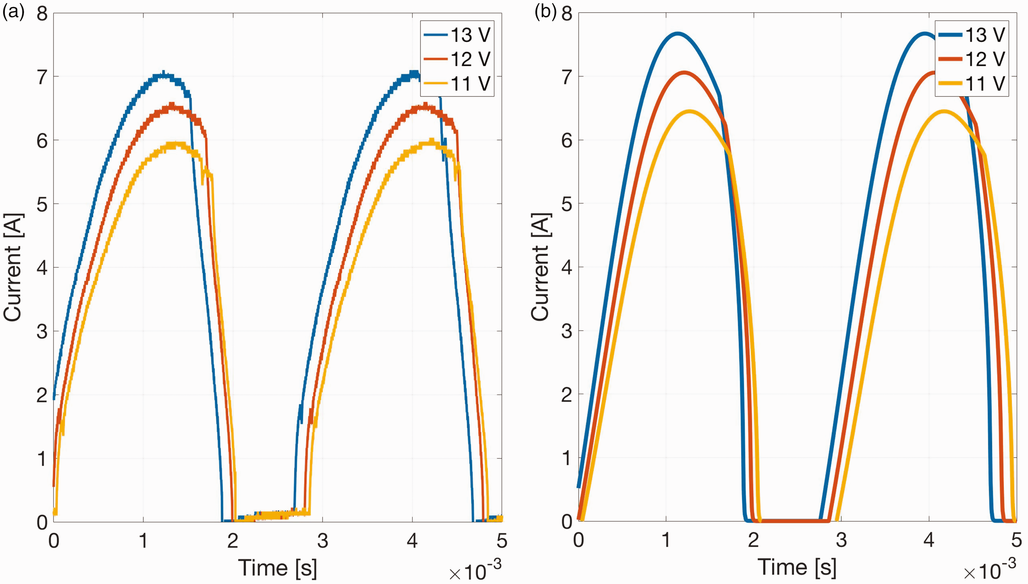
Comparison between measured (a) and simulated (b) current.
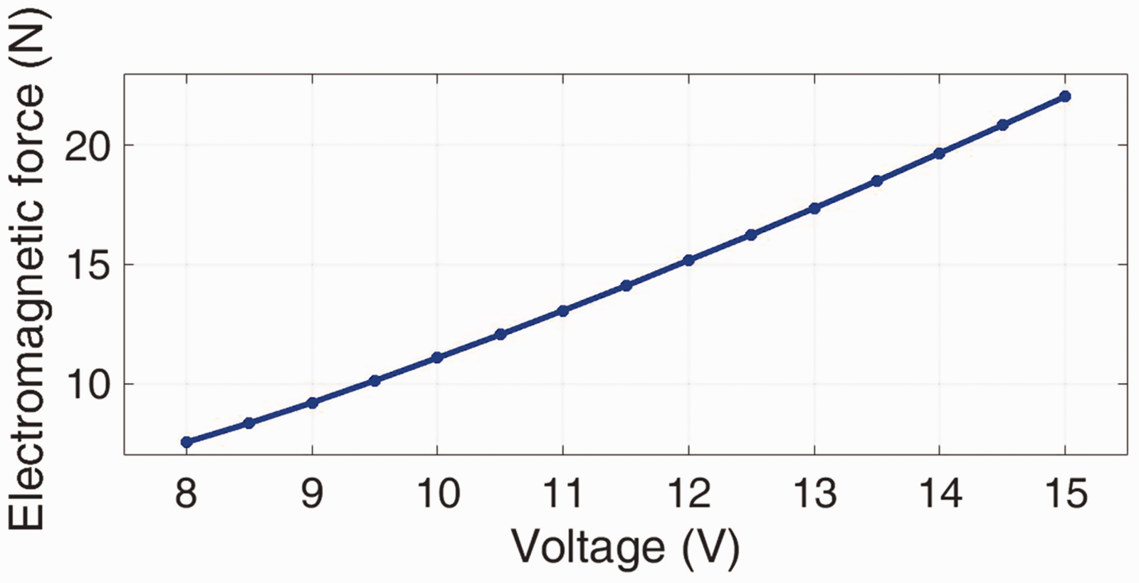
Simulated electromagnetic force against voltage.
Horn on the standard bracket
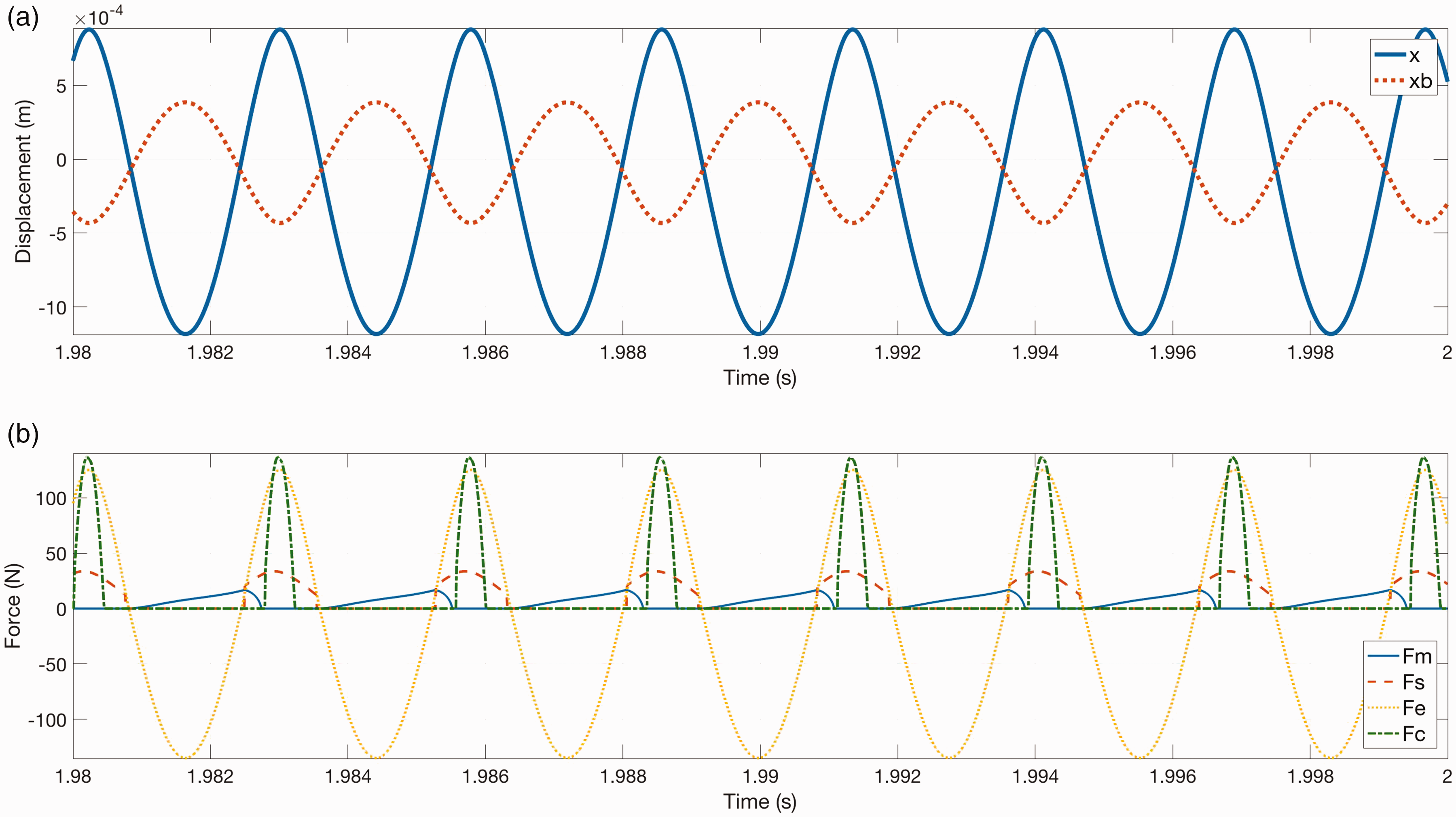
First, the horn mounted on the standard bracket is simulated and the effect of input voltage is analysed. Figure 12 shows displacements x (solid line) and
Simulated displacements (a) and forces (b), standard bracket, 13 V.
Figure 13(a) shows that, if the input voltage is reduced to 8 V, the two nuclei still move in opposition, but the relative displacement of the mobile nucleus with respect to the coil nucleus is smaller than xc and the two nuclei do not touch. This result is confirmed by the plot of forces (Figure 13(b)). The switching phenomenon appears like at 13 V, but there is no contact force and the horn does not emit sound. Similar numerical simulations were carried out for an extended range of voltages (8–14 V, step 0.5 V). Figure 14 shows the frequency of vibration against voltage and the values of voltage that are not able to cause the contact between the nuclei and to emit sound (red dots). The frequency of vibration increases with voltage and there is a good agreement with the acoustic measurements (Figure 7).
Simulated displacements (a) and forces (b), standard bracket, 8 V.
Dependence of oscillation frequency on voltage, numerical results.
Effect of bracket stiffness
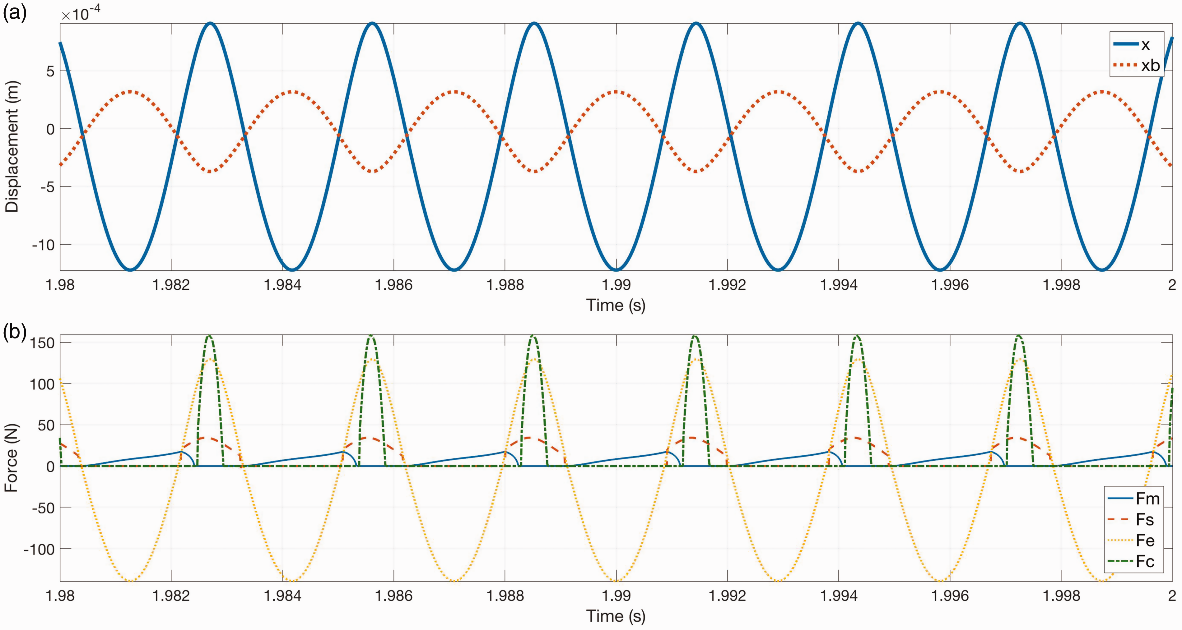
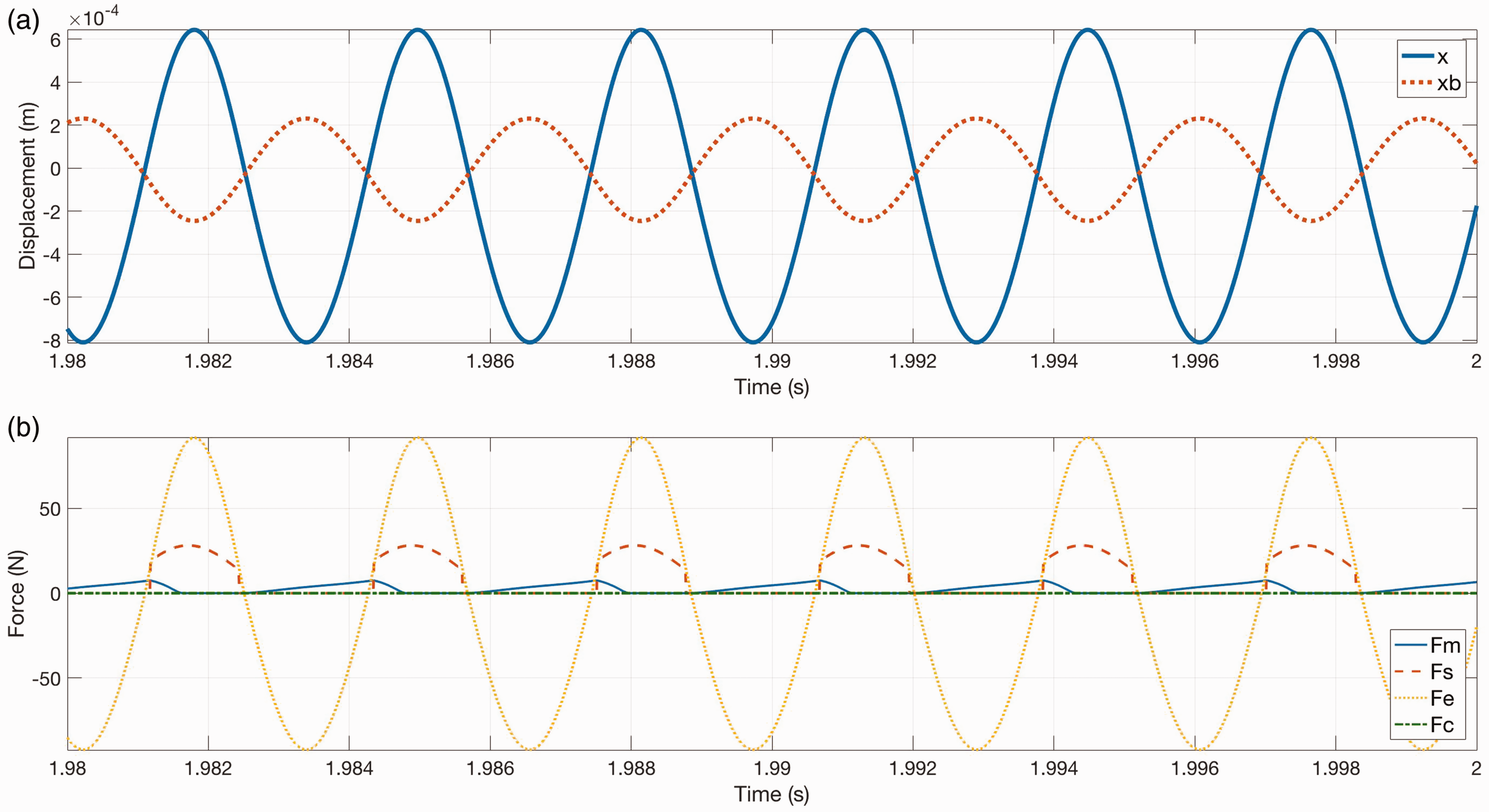
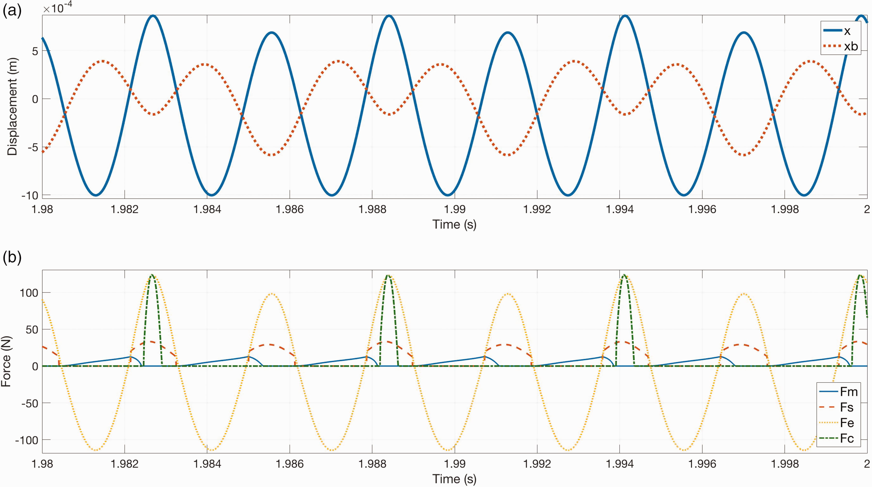
Acoustic measurements reported in ‘Experimental results’ section showed that the horn has a particular behaviour when it is mounted on the bridge bracket that has larger stiffness than the standard bracket. In order to analyse this phenomenon, the horn mounted on the bridge bracket is simulated. Figure 15(a) shows that, when the input voltage is 13 V, the two nuclei move in opposition with frequency 360 Hz; this value is rather close to the natural frequency of the second mode of vibration (in opposition) found by means of linear modal analysis. The relative displacement between the nuclei is larger than xc and there are impacts. The force plot (Figure 15(b)) is rather similar to the force plot of the horn mounted on the standard bracket and excited at the same voltage. If the excitation voltage decreases to 11 V the displacements of the nuclei are still in opposition (see Figure 16(a)), but an amplitude modulation of vibrations appears (like in the beat phenomenon) and the Fourier’s analysis shows that horn vibrations have two harmonic components, the main is at 349 Hz and the secondary is at half frequency (175 Hz).
Simulated displacements (a) and forces (b), bridge bracket, 13 V.
Simulated displacements (a) and forces (b), bridge bracket, 11 V.
This effect can be explained taking into account that:
The system is non-linear owing to the switching phenomenon, the electromagnetic force and the impacts; hence it may exhibit sub-harmonic behaviour with the appearance in the response of terms having sub-multiple frequency of the fundamental frequency of excitation.
17
Sub-harmonic behaviour has been studied and documented in many mechanical systems.18–21 The fundamental frequency of excitation decreases as voltage decreases (see Figure 3 and acoustic measurements). In the bridge bracket, the natural frequency of the in-phase mode of vibration is half the natural frequency of the in-opposition mode (see Figure 8(b)).
Therefore, when the horn is mounted on the bridge bracket and the voltage decreases, a particular condition is met in which the electromagnetic force is able to excite both the in-opposition mode and the in-phase mode owing to a sub-harmonic behaviour. Figure 16(a) shows that the amplitude modulation of vibrations generates displacements able to cause the impact between the nuclei only every two cycles of vibration, hence with a frequency equal to half the fundamental frequency of vibration. Figure 16(b), which shows the forces at 11 V, confirms that the contact force (Fc dotted-dashed line) appears with frequency equal to half the main frequency of vibration. The horn emits sound, but the spectrum contains a component at low frequency and the quality of generated sound is poor. This simulation explains the acoustic measurements presented in Figure 6.
If the voltage decreases further (9 V) the specific condition which allows the excitation of two modes is no more met and the two nuclei vibrate in opposition at lower frequency (338 Hz) (see Figure 17(a)). The amplitude of vibration is lower than in the previous cases and there is no impact between the nuclei (Figure 17(b)) and the horn does not emit sound. The results of simulations carried out with different voltage values are summarized in Figure 14. There is a good agreement with acoustic measurements; in particular, the model predicts the conditions in which the horn does not emit sound.
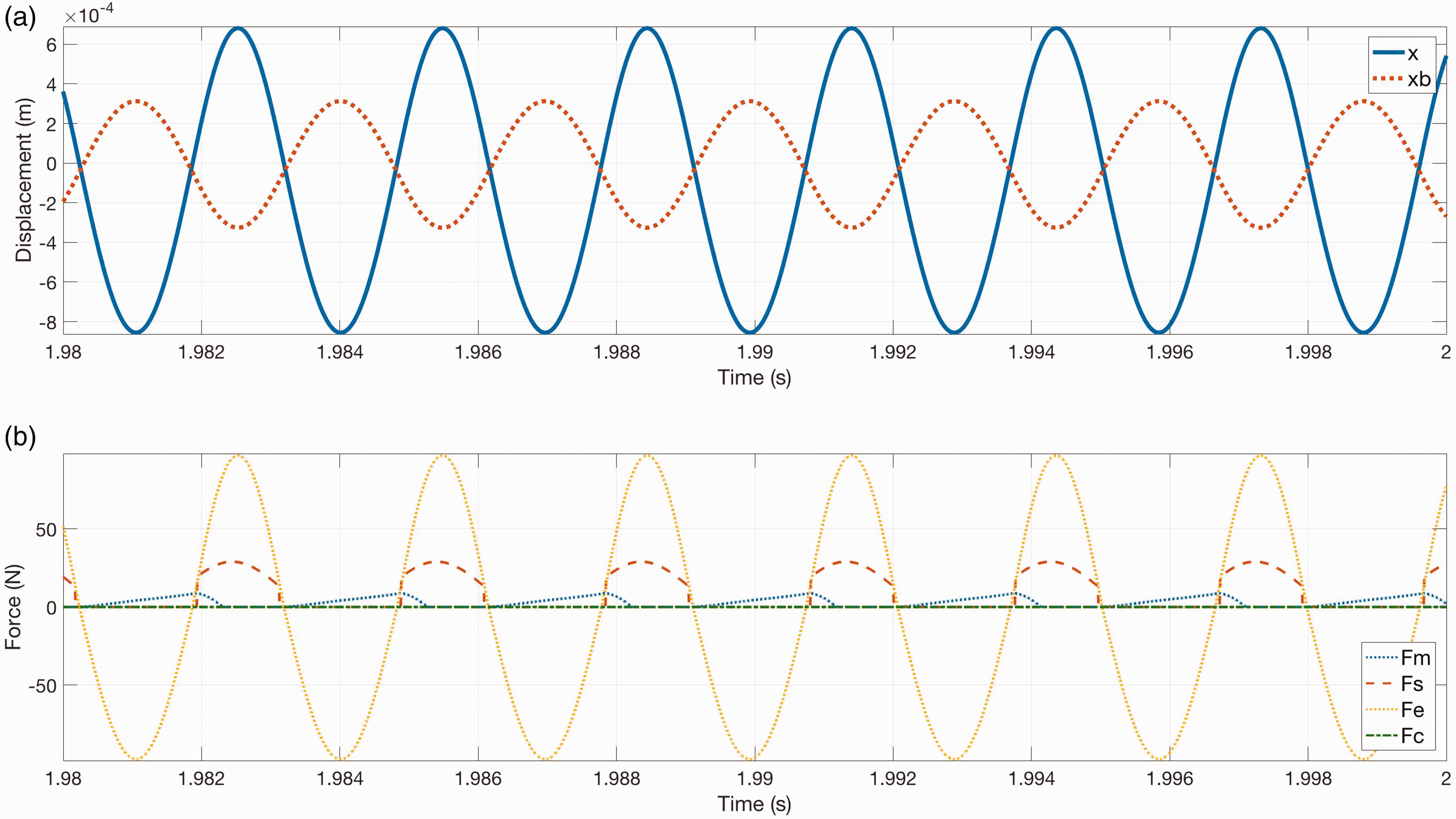
Simulated displacements (a) and forces (b), bridge bracket, 9 V.
Conclusions
The disk horn is an interesting multi-physics system characterized by some non-linear effects. Experimental tests show that variations in the input voltage and in the design of the bracket that connects the horn to the vehicle lead to large variations in the level and quality of generated sound. The disk horn can be divided into two subsystems: the motor and the disk. The motor, which includes the coil, nuclei and membrane can be considered a lumped element vibrating system and it includes the non-linear effects. The disk is a distributed parameter vibrating system, and the shape and density of its modes of vibration determine the acoustic radiation efficiency. Since some tests showed that the operating conditions (input voltage and bracket stiffness) have a very small effect on the high frequency dynamics of the disk, this study focused on the electromechanical phenomena that take place inside the motor of the horn.
A detailed numerical model was developed. Numerical results show that input voltage determines not only the intensity of the electromagnetic force and the amplitude of vibration of the nuclei, but also vibration frequency, since electromagnetic force and vibrations are coupled in a non-linear way. A good correlation between the numerical values of voltage that are able to generate impacts between the nuclei and the experimental values of voltage that make possible sound emission is found.
When the horn sounds well, a specific mode of vibration of the motor is excited with the two nuclei that move in opposition, the motion of the coil nucleus being allowed by bracket compliance. The in-phase mode of vibration of the nuclei, which has lower natural frequency, is not excited. Acoustic tests show modifications in sound spectrum (with a worsening of generated sound), if the horn is mounted on a bridge bracket having larger stiffness than the standard cantilever bracket. Experimental modal analysis and the numerical model explain these phenomena. Modal analysis shows that in the bridge bracket the natural frequency of the in-opposition mode is twice the one of the in-phase mode. Numerical results show that when the input voltage and frequency decrease a condition is met in which the non-linear system exhibits a sub-harmonic behaviour, that is the response has both a component at the frequency of excitation and components at a sub-multiple of this frequency.
In conclusion, the numerical model of the electromechanical sub-system of the horn is able to explain many effects found during the actual functioning of car horns. In the future, the model will be useful for the design of new horns.
Footnotes
Declaration of conflicting interests
The author(s) declared no potential conflicts of interest with respect to the research, authorship, and/or publication of this article.
Funding
The author(s) disclosed receipt of the following financial support for the research, authorship, and/or publication of this article: The research was carried out in the framework of the research program: ‘Multi-physical methods for producing horns particularly suited to different vehicles’ funded by Regione Veneto (grant number 2105-22-2216–2016).