
Abstract
This paper presents the design and performance evaluation of a multi-disc magnetorheological fluid (MRF)-based brake (MRB) for A00-class minicars. The braking performance of the MRB is studied by means of theoretical analysis and experimental verification. Firstly, the MRB is designed according to the shear model of the MRF, and the structure optimization is carried subsequently. Secondly, multi-physical simulations of the MRB are conducted to investigate the transient temperature field, thermal stress and thermal strain distribution of the MRB under different braking models; Finally, a performance evaluating testbed is built to experimentally assess the braking performance of the MRB. The results indicate that the theoretical braking torque of the MRB fulfills the target value. The thermal strain-induced deformation of the disc is minimal and has a negligible effect on the torque output. In addition, the MRB is experimentally validated to exhibit excellent braking performance in terms of sufficient torque output capacity, rapid response, low temperature rise characteristic, as well as favorable velocity following property.
Keywords
1. Introduction
With the rapid development of vehicles toward low-carbon (Brazil et al., 2019), electrified (Vyacheslav, 2020), and intelligent direction (Jin et al., 2021), the demand for excellent wire control vehicle brakes is urgent increasingly (Chen et al., 2021; Durail et al., 2018). The traditional mechanical friction brakes have several defects including low braking efficiency, thermal decline, severe wear, and unstable driving during braking (Zhong, 2013). The magneto-rheological fluid (MRF)-based brake (MRB) is capable to realize controllable and flexible braking of vehicles by solely adjusting the coil current (Kaide et al., 2020; Wang et al., 2023). Due to its advantages of millisecond response velocity, simple control, and low energy consumption, the MRB can reduce braking distance while used as an alternative to vehicle brakes (Wang et al., 2013; Xiong et al., 2023). Besides, it is more suitable for seamless integration with other electronic control units to achieve collaborative control of electric vehicles, thus reducing the complexity of the vehicle control systems (Taichiro et al., 2019).
In the realm of the MRB, many scholars contribute to the field of structural design and performance analysis. Li et al (2003) proposed an MRB which is simple, quiet, and responsive. Yun et al. (2017) introduced a novel MRB that is demonstrated to be feasible for the velocity regulation of rotating systems. Actually, the performance of the MRB is influenced by multiple factors, such as size of the structure and the number of discs. Song et al. (2017) investigated the effect of gap size on the braking performance of the MRB. The results confirmed that the gap size significantly influences the braking performance. Hu et al. (2021) and Shiao et al. (2021) conducted a related study on multi-disc MRB, and the results indicated that the braking performance of the MRB can be improved by increasing the number of brake discs. In the follow-up research, Shiao and Kantipudi (2022) proposed an MRB which adopted dual disc-type construction to achieve high torque density. As above mentioned, the multi-disc structure can provide a relatively high torque density during braking. Moreover, Nguyen et al. (2022) proposed a novel MRB with a tooth-shape rotor. The tooth rotor can enlarge the interface area between the rotor and the MRF which can improve performance of the MRB such as compact size and high braking torque.
It is well-known that the braking torque of the MRB is mainly produced by the magnetorheological effect of MRF under the excitation of a magnetic field (Wang et al., 2015). During the braking process, the shear friction between the disc and the MRF definitely generates enormous amounts of thermal energy, which in return adversely affects the braking performance of the MRB. Actually, the braking performance of the disc-type MRB is affected by various factors. Such as the working temperature (Wang et al., 2017), the gap size between two discs (Kikuchi et al., 2011), the magnetic particle distribution induced by the centrifugal effect (Tian et al., 2021), the current magnitude and direction of each coil (Wu et al., 2023), and so on. Among these factors, the temperature effect is reported to has a significant impact on the torque output performance of the MRB since the MRF is a temperature-dependent material (Wang et al., 2014). Therefore, some related research works were performed on the temperature characteristics of the MRB (Sarkar et al., 2015). Falcao and Luis (2004) proposed an MRB featuring the water-based MRF as the braking medium for vehicles, and simulated and analyzed the temperature field under repeated cycle braking conditions. Park et al. (2006) analyzed the internal heat transfer phenomenon of a double-disc MRB using ANSYS software. Patil et al. (2016) carried out finite element analysis (FEA) simulations to reveal the internal temperature distribution of the MRB during the working process. Moreover, the heat generated in the gaps between two discs leads to the thermal deformation of discs which changes the gap size and also affects the braking performance of the MRB. Szelag et al. (2023) analyzed the coupling field in the MRB. They have considered the temperature, nonlinearity of the magnetic circuit, and rheological properties of the MRF. Hence, the thermal-structure coupling simulation will be carried out in this study.
The main focus of this work is on the development and performance evaluation of a multi-disc MRB (MDMRB) for A00-class minicars. In order to accomplish this goal, a novel MDMRB was presented to improve the braking performance. In this paper, the design of the proposed MDMRB is first described in detail. Then, we built a mathematical model of its braking torque and describe the multi-physical field simulations that was conducted to validate the designed structural. A prototype was fabricated and assembled, and we describe the design of the experimental setup for testing this prototype. Experimental results concerning the temperature characteristics, torque output capacity, and velocity-following property. Research results may serve to provide guidance on the design, heat dissipation, and braking performance evaluation of the MRB.
2. Design and analysis of the MDMRB
2.1 Basic structure
Figure 1 shows the assembly of the proposed MDMRB. The brake utilizes the multi-disc brake form to achieve a high torque density. The brake mainly includes spindle part, magnetic circuit part, magnetic isolation part, coil, shell, sealing elements, bearings, and fasteners. Among them, the spindle part is composed of a rotating shaft, a rotor, a brake disc, and a shaft sleeve. The drive and driven rotors are equipped with several brake discs by using the spline connection, and they are respectively connected to the drive and driven shaft through a set of bolts. The closed cavity formed by the left, right, and upper magnetic plates, and the magnetic isolation ring is used to place the excitation coil. Moreover, the magnetic circuit part and the magnetic isolation module are used to make the magnetic flux conduct in the expected direction and reduce the magnetic leakage. There is a cavity between the left and right magnetic disc whose main role contains two parts: 1) reduce the total mass of the MDMRB; 2) the channel of water cooling.
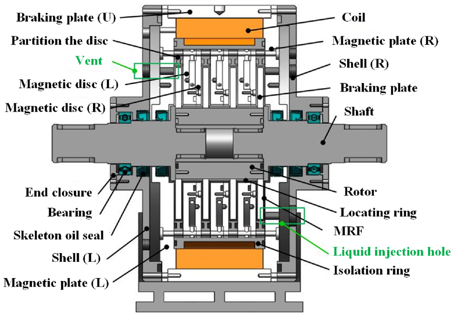
Assembly of the MDMRB.
After the installation of the MDMRB, the MRF can be injected through the injection hole below the right magnetic plate. When the MRF has filled the whole airtight cavity, plug the injection hole and exhaust hole with a screw plug, and then the MDMRB can work normally. In the braking process, a current is applied to the coil to produce a magnetic field in the gap between the discs. The MRF contained in the gaps is induced to transform from a Newtonian fluid state to a solid-like state by the magnetic field in milliseconds, which presents the shear yield stress to hinder the rotation of the discs. In addition, the magnetic field intensity can be adjusted by solely changing the applied coil current, and thus the output braking torque of the MDMRB can be steplessly controlled.
2.2 Theoretical analysis of the braking torque
2.2.1 Target braking torque
Referring to reference (Liao et al., 2020), the moment of inertia I and the target braking torque Mc of a vehicle brake can be expressed as
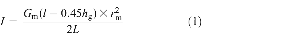
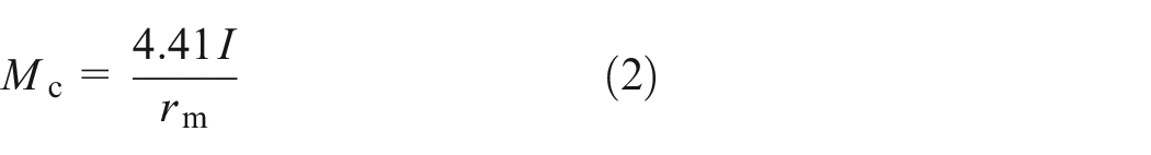
where Gm is the mass of fully loaded vehicle, l is the distance from center of gravity to front axis, hg is the height of full load center of gravity, rm is the wheel rolling radius and L is the wheelbase.
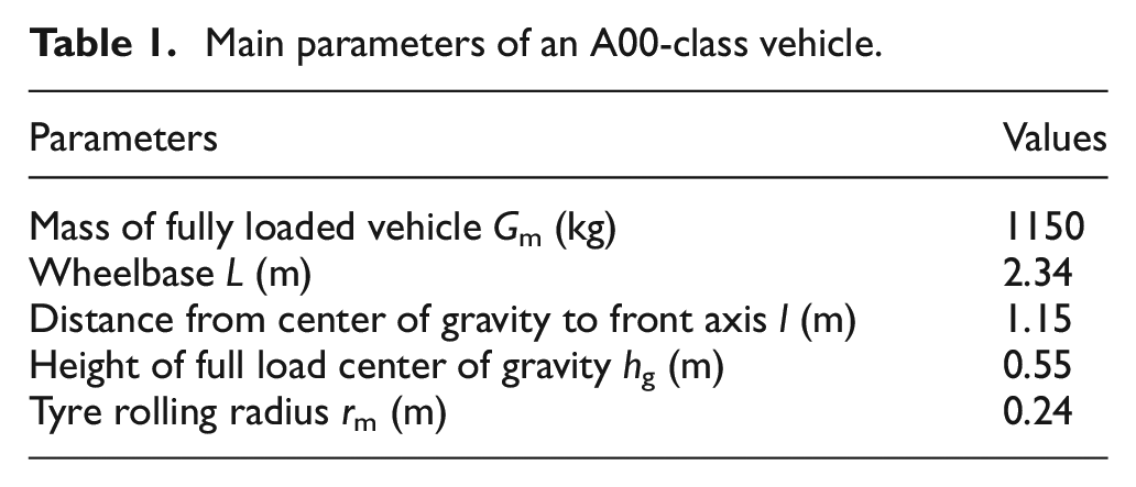
An A00-class minicar with its main parameters shown in Table 1 is chosen as the target vehicle. Combined with equations (1) and (2), the target braking torque of the MDMRB can be calculated as 235 Nċm.
Main parameters of an A00-class vehicle.
2.2.2 Mathematical model of braking torque
Characteristics of the MRF can be described by the Bingham model, in which the total shear stress τ is given by

where τB is the shear yield stress due to the magnetic field B, η is the constant plastic viscosity of the fluid, and γ is the shear strain rate.
Theoretical analysis of the braking torque is carried out by using the micro-element method. As shown in Figure 2, the inner and outer radius of the brake disc are R1 and R2, and the gap width is h. In the any radius r, a micro-segment of the gap dr is chosen and the braking torque dT can be expressed as

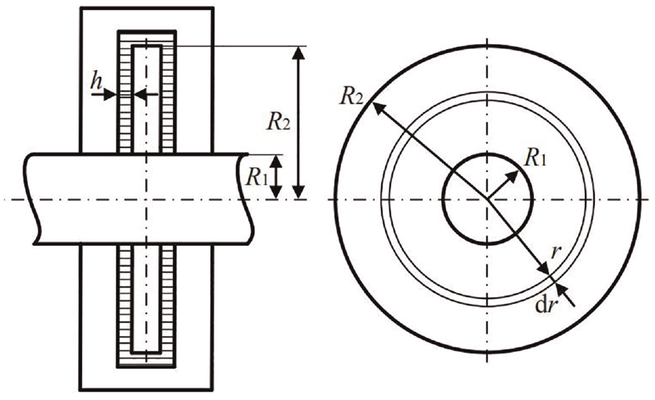
Diagram of the MRB torque model.
The shear strain rate at radius r is
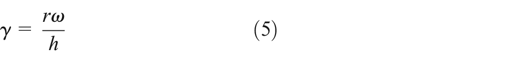
where ω is the angular velocity of the discs and h is the width of the working gap.
According to equations (3)–(5), the total braking torque T generated by the MDMRB with n brake discs can be calculated as
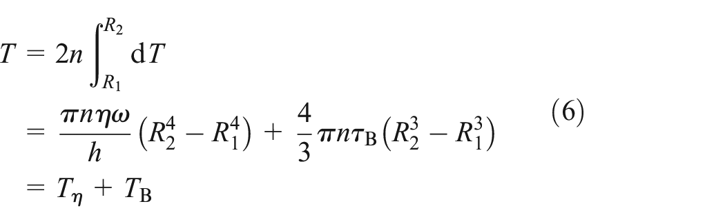
As seen in equation (6), the total braking torque T consists of TB and Tη. Where,
2.2.3 Numerical analysis of braking torque
In the present study, a commercial MRF (MRF2035, provided by Ningbo Shangong Intelligent Security Technology Co., Ltd., China) is employed for its excellent rheological performance. Figure 3 shows the magnetic flux intensity versus shear yield stress.
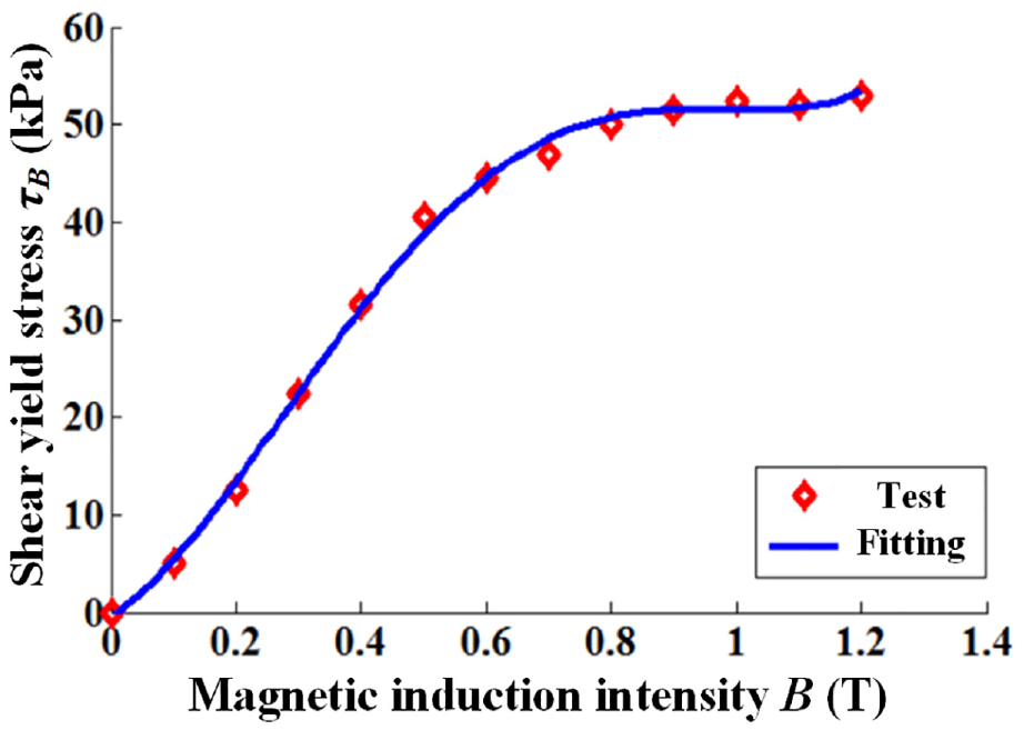
Magnetic induction intensity versus shear yield stress of the MRF.
Then, the equation of the shear yield stress τB is derived from Figure 3 using the exponential-fitting method as
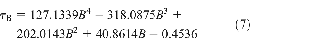
where B is the magnetic induction intensity.
As shown in Figure 3, the increase curve of shear yield stress can be approximated as a straight line when the magnetic induction strength is 0–0.5 T. The corresponding shear yield stress of the MRF is 40.06 kPa for a magnetic induction intensity of 0.5 T. Thus, in order to fulfill the required braking torque of 235 N·m, the main dimension parameters of the MDMRB are designed as shown in Table 2.
Main parameters of the MRB.
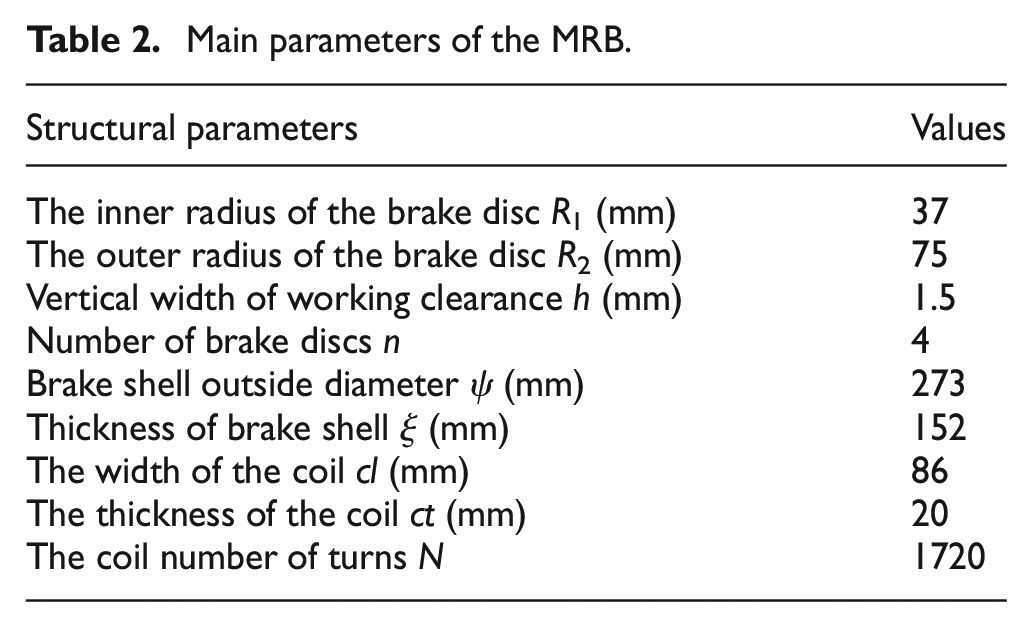
Figure 4 exhibits the Simulink model for the braking torque investigation of the MDMRB. After importing the main dimension parameters of the MDMRB into the simulation model, the braking torque versus the magnetic induction intensity is presented in Figure 5. The braking torque increase with the magnetic induction intensity exhibits a trend of first rapidly and then gently. It is obvious that the increasing magnetic induction intensity can effectively improve the braking torque, especially in the range from 0 to 0.8 T. In addition, the braking torque is obtained as 242.16 Nċm for a magnetic induction intensity of 0.5 T, which can fulfill the design requirements.
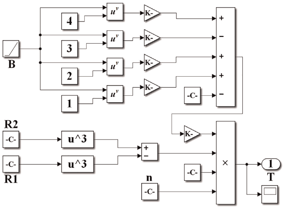
Simulink model of the MDMRB.
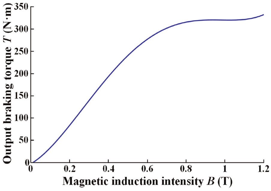
Magnetic induction intensity versus braking torque.
Multi-physical field simulations
Electromagnetic field simulations
Electromagnetic field (EMF) simulations of the MDMRB were conducted to accurately characterize the distribution of magnetic induction intensity at the working gap using the software ANSYS.
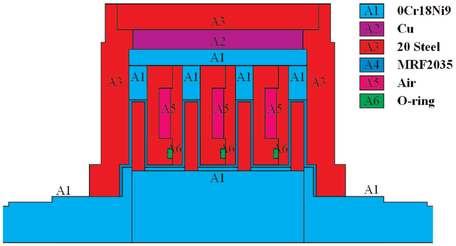
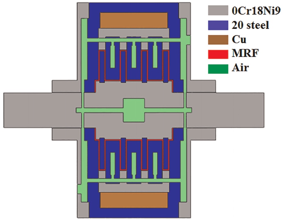
A FEA model of the MDMRB was developed as shown in Figure 6. In the magnetostatic simulation, the relative permeabilities of the non-ferromagnetic materials, including air, Cu, 0Cr18Ni9 and O-ring, were all set to 1. The MRF and 20 steel are nonlinear ferromagnetic materials, whose material properties are the defined by the B–H curves. The current was applied on the coil area as a current density load and the coil current density Γ is given by
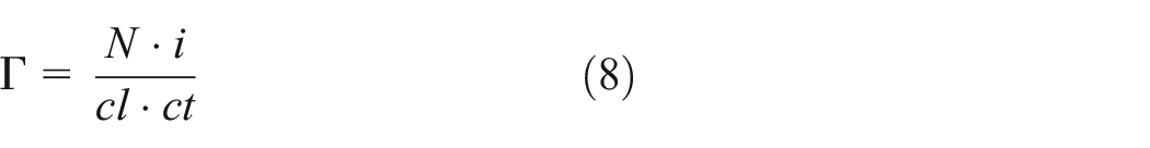
where N is the number of turns, i is the coil current, ct is the coil width, and cl is the coil thickness.
Simulation model of the MDMRB.
The outer diameter of the copper wire used in the coil is 1.02 mm, and the maximum allowable operation current of the copper wire is 3.2 A. Thus, the maximum current of the MDMRB is set to 3 A.
Figure 7 indicates the simulation results of the magnetic circuit in the case of an input current 3 A. As observed, the magnetic flux lines are strictly limited and oriented perpendicular to the brake disc in the magnetic circuit design. The magnetic induction intensity distributes uniformly at the working gaps and the maximum induction appears in the upper plate with a value of 1.676 T. The results indicate the reasonability of the magnetic circuit design and the material selection. It should be noted that the area A5 in Figure 6 is hollow which was designed to reduce the total mass of the MDMRB and as a reserved water cooling channel. Therefore, as observed in Figure 7, the magnetic flux density in the corresponding area is 0.
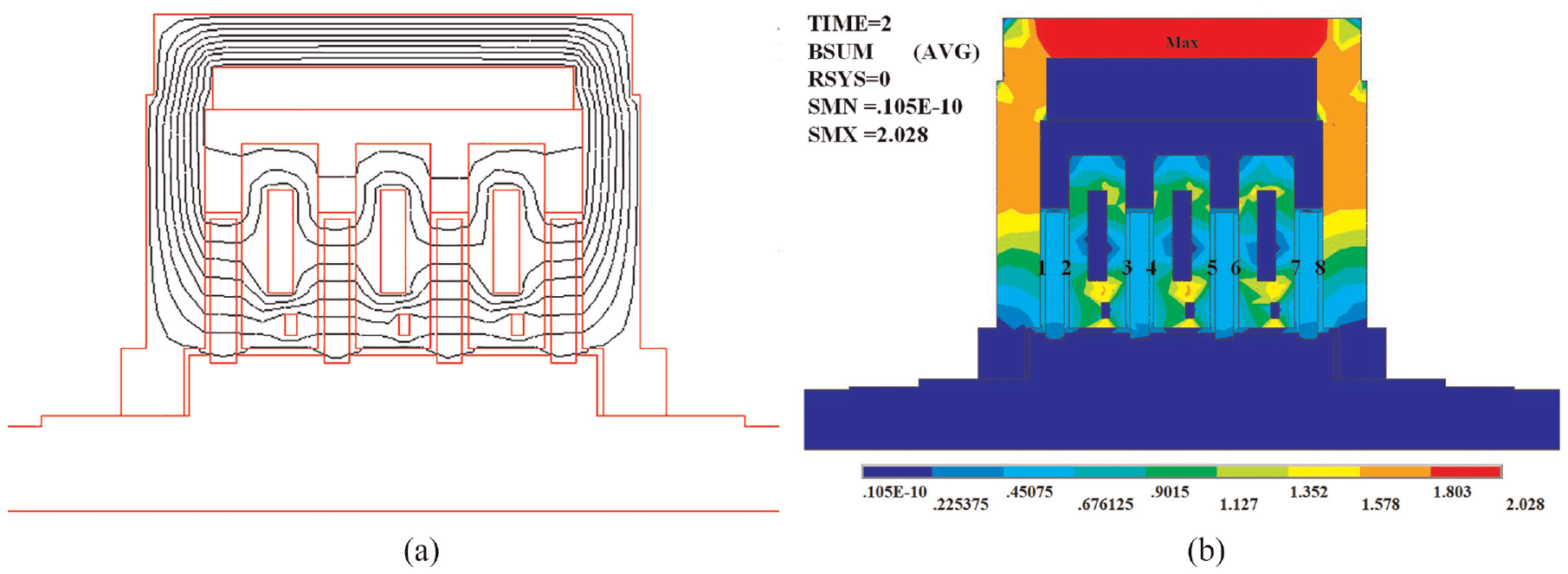
EMF simulation results: (a) magnetic flux distribution and (b) magnetic induction contour.
Several nodes in the working gap are chosen to analyze the magnetic induction distribution in the radial direction with different currents. The distribution is shown in Figure 8. The magnetic induction intensity increases along the radial direction of the disc from r = 0 to r = 0.005 m. The magnetic induction presents a symmetrical distribution with respect to the gap center. However, the magnetic induction presents as basically uniform in each working gap, with an average value of 0.56 T for a current of 3 A. According to the results in Figure 5, the theoretical braking torque is calculated as 263.86 Nċm, which can fully meet the design target of 235 Nċm.
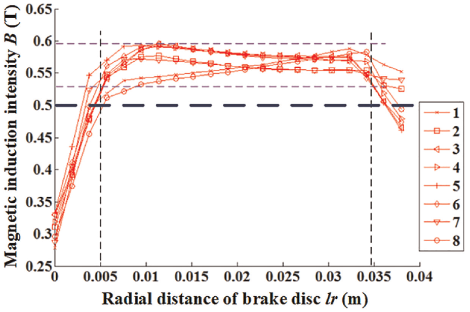
Variation of magnetic induction intensity in the radial direction
Simulate and analysis of temperature
During braking, the heat generated by the shear friction between the discs and the MRF can be equivalent to the loss of kinetic energy of the vehicle. At the braking moment of t, a micro-segment of the braking time Δt is chosen for analysis. The reduction of kinetic energy
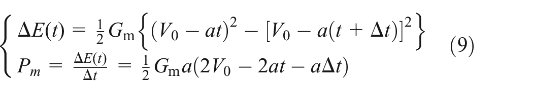
where V0 is the initial velocity, Gm is the mass of fully loaded vehicle, and a is the deceleration velocity of vehicles.
According to Ohm’s law, the heating power Pc of the coil is expressed as

where i is the coil current, Rc is the resistance of the coil, N is the number of turns of the coil,
Due to the temperature difference, a natural heat convection occurs between the shell surface and the surrounding environment while the MDMRB is operation. According to Newton’s cooling law, the natural heat convection power Pa is described as

where ha is the coefficient of natural heat convection, Au is the area of thermal convection, Tu is the surface temperature of the shell, and Te is the ambient temperature.
Therefore, the power expression of energy conservation can be written as
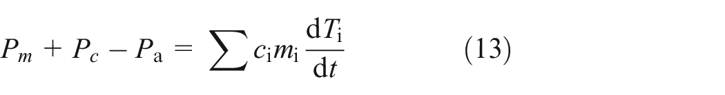
where ci, mi, and dTi/dt are the specific heat capacity, mass, and temperature change rate of each component of the MDMRB, respectively.
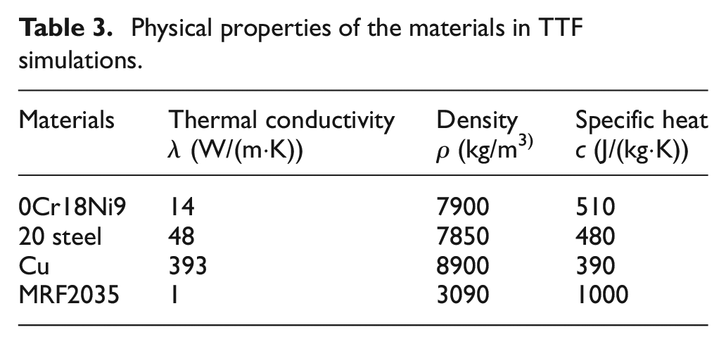
Figure 9 shows the simplified simulation model of transient temperature field (TTF) simulations. The physical properties of the materials are presented in Table 3.
Simulation model of TTF.
Physical properties of the materials in TTF simulations.
The initial temperature of the MRB is set to 25°C. The thermal loads include the heat generation rates at the coil and each working gap, as well as the natural heat convection and the thermal radiation between the shell surface and the surrounding air. In this study, a composite heat transfer coefficient is chosen as ha = 9.7 W/(m2ċ°C). The thermal loads and boundary conditions can be imported into the ANSYS Workbench platform in the form of constants or functional expressions (Wang et al., 2018).
Assuming that all of the reduced kinetic energy of the vehicle during braking is converts into shear friction heat. Therefore, the heat generation rate

where Vm is the volume of the MRF.
Also, the heat generation rate

where Vc is the volume of the coil can be expressed by

where cl, rc1, and rc2 are the widths, inner radius, and outer radius of the coil, respectively.
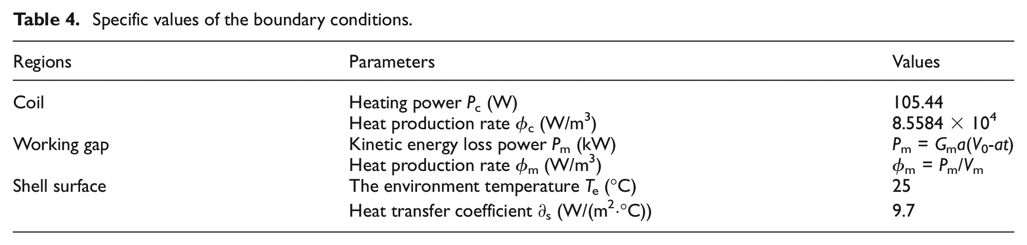
The initial velocity and deceleration of the vehicle in TTF simulations are set as v0 = 80 km/h and a = −2.5 m/s2 respectively. Combined with equations (9)–(16) and the structural parameters of the MDMRB, the variations of the heat generation rate in the working gap are calculated as shown in Figure 10. Specific values of the boundary conditions are given in Table 4.
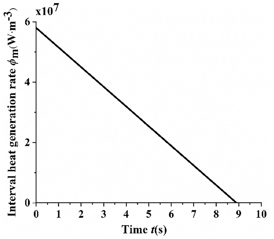
Heat generation rate versus time.
Specific values of the boundary conditions.
The temperature distribution of the MDMRB at the end of simulation (t = 8.88 s) is presented in Figure 11. The temperature appears highest in the working gaps. Figure 12 shows the variation curve of the highest temperature with time. During the whole braking process, the maximum temperature increases rapidly and then decays slowly with time. In specific, the maximum temperature reaches up to 43.2°C at 3.66 s, and it dropped to 36.5°C at the end of vehicle braking.
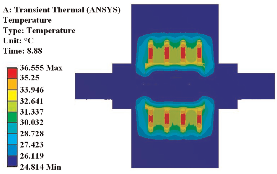
Temperature field distribution of the MDMRB.
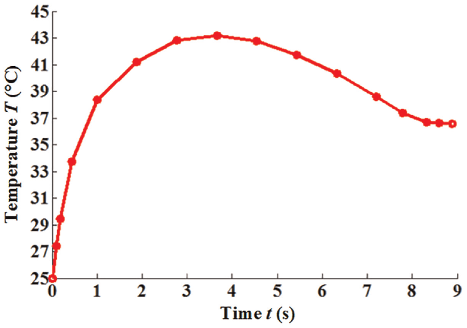
Variation curve of the highest temperature with time.
3.3 Thermal stress and thermal strain
In this design, the size of the working gaps is only 1.5 mm, the generated heat may leads to the thermal deformation of the discs to change the gap size and affect the braking performance of the MDMRB. Therefore, the thermal-structure coupling simulation was performed using the ANSYS Workbench platform. Table 5 presents the mechanical properties of the materials.
Mechanical properties of the materials.
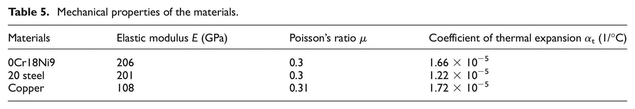
Figure 13 exhibits the thermal stress distribution contour of the MDMRB at 3.66 s. Due to the heat accumulation, a large thermal stress is produced in the disc area. The maximum stress at the moment of the highest temperature (t = 3.66 s) is 43 MPa, which is visibly lower than the allowable stresses of stainless steel and 20 steel.
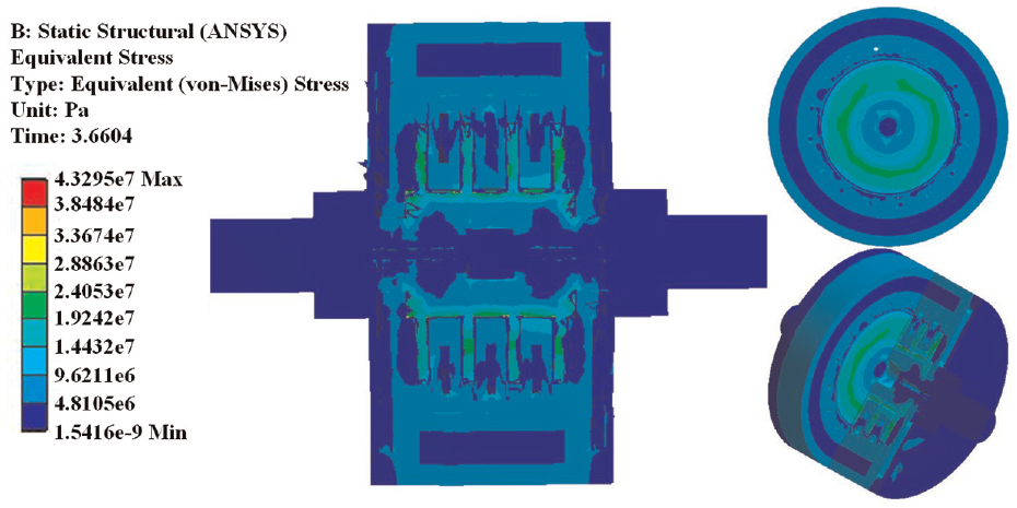
Thermal stress distribution contours of the MDMRB.
At the same conditions, the thermal strain distribution contour of the MDMRB is shown in Figure 14. In the figure, the thermal strain also presents the highest at the brake discs. However, the excessive deformation of the discs will affect the braking stability of the MDMRB. Figure 15 shows the axial deformation of the discs in the radial direction at 3.66 s. The maximum axial deformation of the discs is found to be less than 6 μm, much lower than the gap thickness (1.5 mm). Thus, it can be concluded that the effect of thermal strain on the braking performance is negligible.
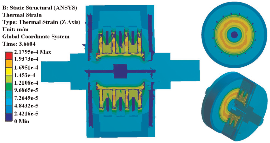
Thermal strain distribution contours of the MDMRB
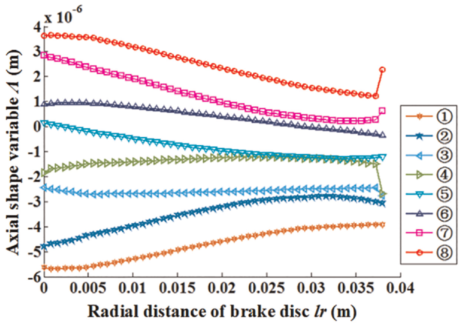
Axial deformation of discs in radial direction
4. Experiments
The experimental prototype of the MDMRB is fabricated and assembled, as shown in Figure 16, the shell is fixed on the pedestal casted in aluminum alloy.
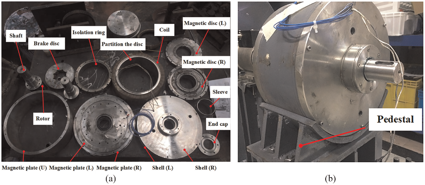
Experimental prototype of the MDMRB: (a) main components and (b) prototype assembly.
An experimental setup, shown physically in Figure 17, was established for performance evaluation of the MDMRB. It is mainly consists of an electric motor, a torque/velocity sensor, a converter, a flywheel set, the MDMRB prototype, as well as several data and signal collection instruments. The experimental steps are as follows: 1) disconnect the coil circuit after set the output current value of the programmable power supply (PPS); 2) adjust the output frequency of the converter according to the initial braking velocity; 3) turn on the electric motor to drive the flywheel set till it reaches up to the target velocity to simulate the kinetic energy of the vehicle; 4) when the velocity reaches the target value (equivalent initial braking velocity) and keeps it for 5 s, close the frequency converter and disconnect the coil circuit, and then the MRB intervenes in the braking; 5) turn off the PPS and save the experimental data after the flywheel set stops rotating.
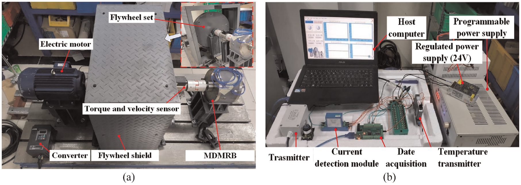
Experimental system for the MDMRB: (a) mechanical transmission system and (b) data acquisition and control system.
4.1 No-load output characteristic
It is well-known that the viscosity of MRF also produces resistance to consume the kinetic energy of the vehicle during braking. The no-load (the coil current is 0 A) torque output characteristic experiments were conducted in the case of three different initial braking velocities v = 20, 40, and 60 km/h and the results are presented in Figure 18.
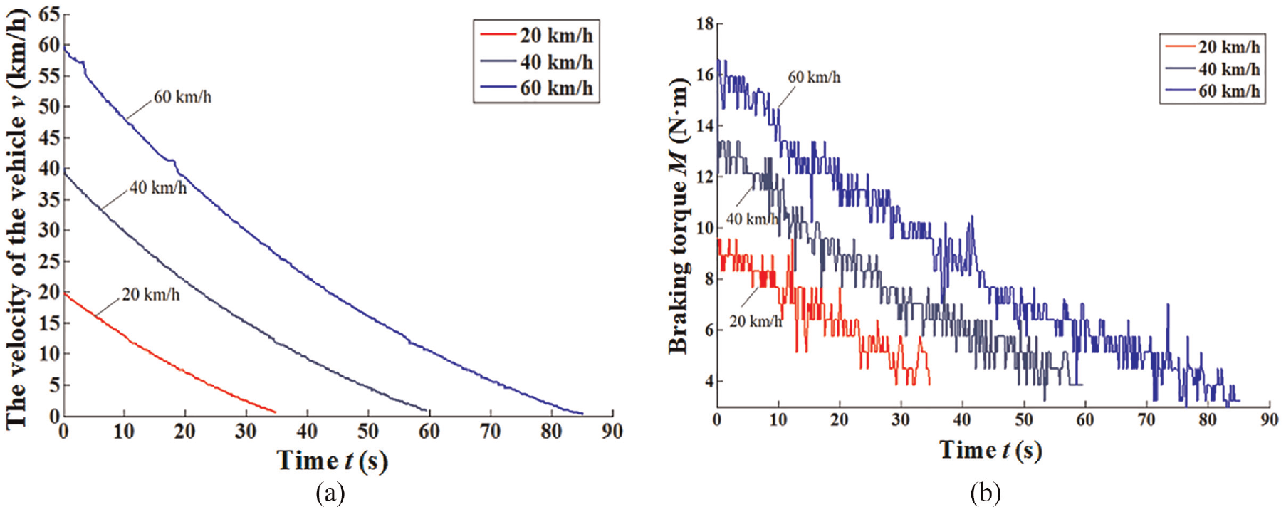
No-load torque output characteristic curves for different initial braking velocities: (a) vehicle velocity versus time and (b) no-load braking torque versus time.
As shown in Figure 18(a), the braking deceleration gradually decreases with time. The total braking times in no-load conditions are 34.8, 59.6, and 85.2 s for different initial braking velocities of 20, 40, and 60 km/h, respectively. In Figure 18(b), the no-load braking torque decreases approximately linearly during the entire braking process, which is in accordance with the equation (6) that the viscous resistance of the MDMRB is proportional to the vehicle velocity.
4.2 Braking performance
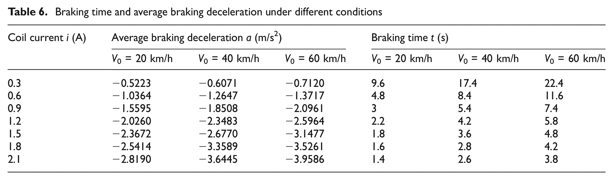
In this section, braking experiments were carried out under various conditions to verify the braking performance of the MDMRB prototype. Figure 19 shows the variation curves of vehicle velocity with different initial braking velocities and coil currents. It is found that the variations of velocities are basically consistent for different conditions. Also, the fluctuation of braking deceleration is almost negligible for a constant coil current. The phenomenon indicates that the MDMRB exhibits good braking characteristics in vehicle braking. The braking deceleration increases with the coil current. However, it slightly differs from each other under different initial braking velocities, which are mainly affected by the instability of the braking torque. Table 6 lists the braking time and average braking deceleration under different conditions.
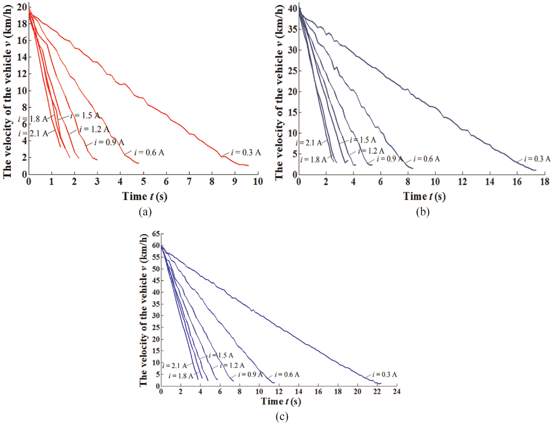
On-field vehicle velocity under different initial braking velocities during braking process: (a) V0 = 20 km/h, (b) V0 = 40 km/h, and (c) V0 = 60 km/h.
Braking time and average braking deceleration under different conditions
4.3 Braking torque characteristic
Experiments were carried out to investigate the stability of the braking torque during the vehicle braking process. Three initial braking velocities v = 20, 40, and 60 km/h and four coil currents i = 0.3, 0.9, 1.5, and 2.1 A were selected for the experiments. The results are shown in Figure 20. It is identified that the braking torque is closely related to the coil current. However, it slightly decreases due to the reduction of the viscous torque at the end of the vehicle braking. Moreover, the fluctuation range of braking torque becomes more obvious for a larger coil current. The phenomenon is mainly caused by the sharp temperature increment which reduces both the dynamic viscosity and magnetizability of the MRF (Wang et al., 2014).
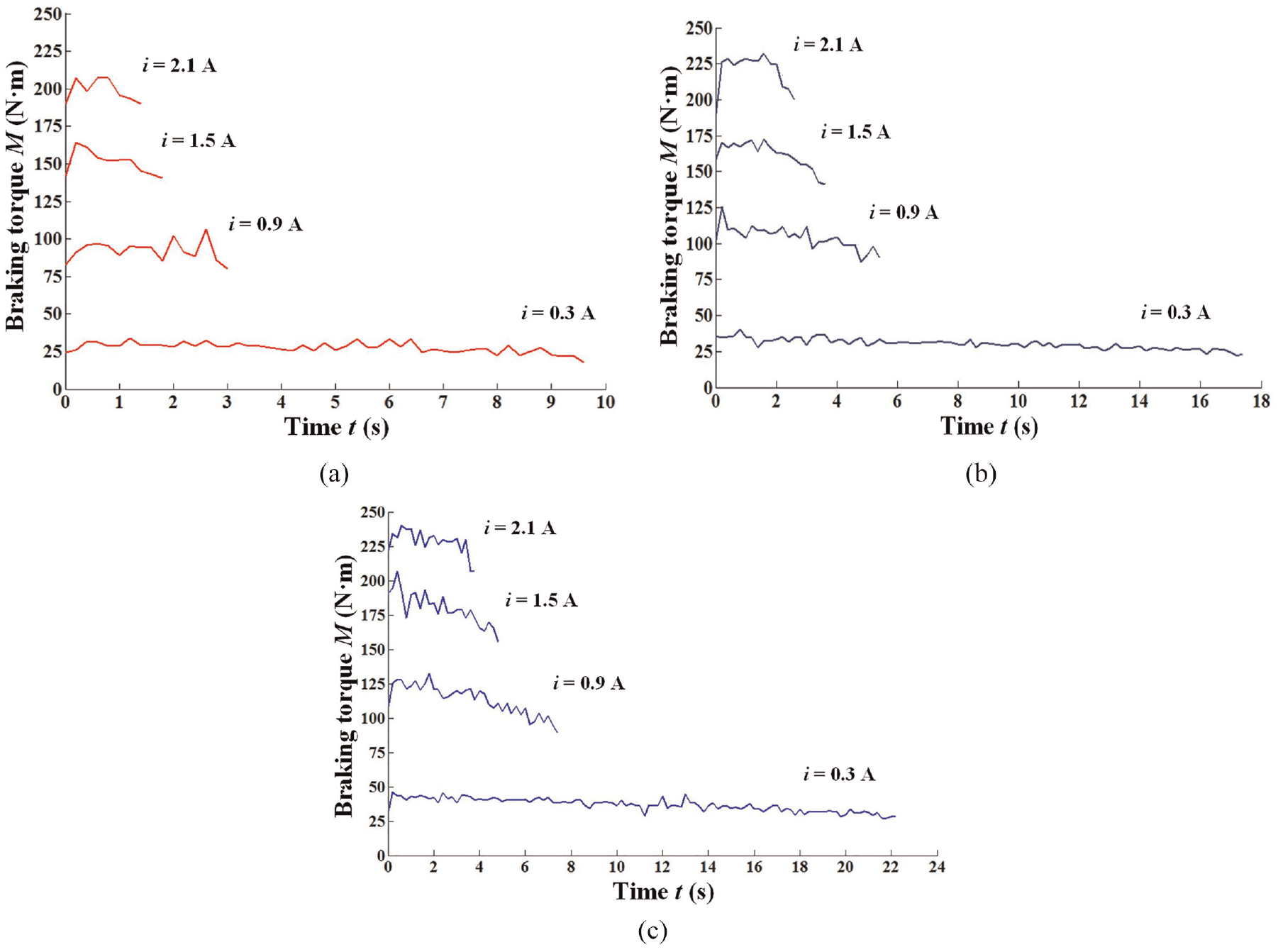
Variation curves of braking torque with operating time: (a) V0 = 20 km/h, (b) V0 = 40 km/h, and (c) V0 = 60 km/h.
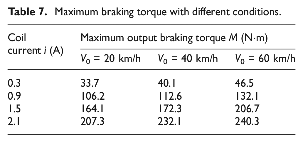
Table 7 shows the maximum braking torque for different coil currents and initial braking velocities. As can be seen that the maximum braking torque exceeds the design value but it is lower than the simulation value in section 2. The reasons are mainly as follows: 1) the performance parameters of the MRF has a certain deviation from the theoretical valves; 2) the EMF simulation model is slightly different from the actual working condition.
Maximum braking torque with different conditions.
The response time of brake is strongly dependent on the magnitude of the applied current (Strecker et al., 2015). The current response time is the time needed for reaching the target value after a step of the control signal. In view of this, it is expected that the response time of the braking torque is as short as possible to ensure braking safety. To investigate the dynamic characteristics of the proposed MDMRB, the step response experiments were performed as presented in Figure 21. In the experiments, the initial braking velocity is 60 km/h and the coil currents are 0.9, 1.5, and 2.1 A, respectively. The response time of the braking torque for the proposed MDMRB increases with the value of the coil current. Generally, the response time of the braking torque for the proposed MDMRB is about 200 ms.
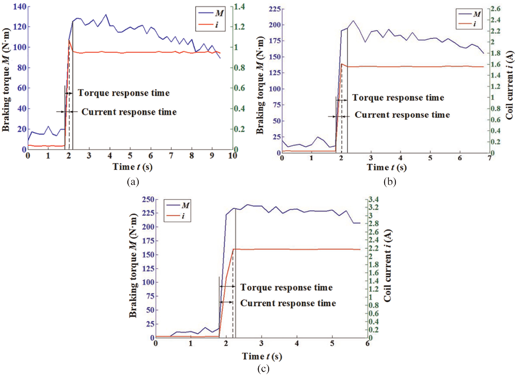
Response curves of the braking torque and coil current for the MDMRB: (a) i = 0.9 A, (b) i = 1.5 A, and (c) i = 2.1 A.
4.4 Temperature characteristic
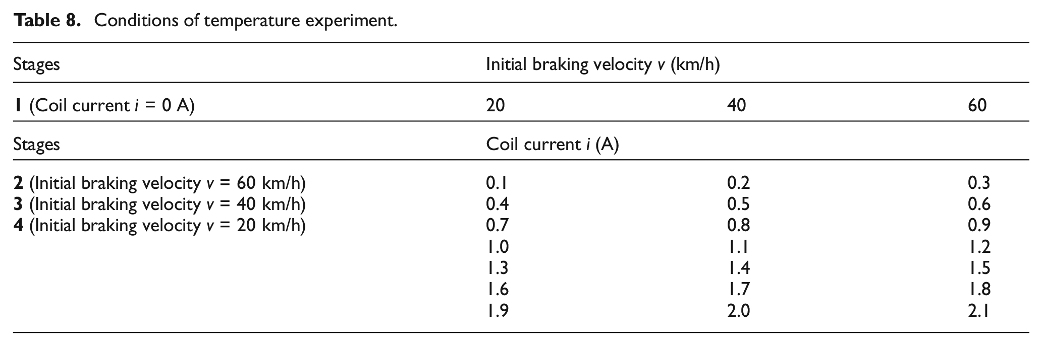
It is well-known that a large amount of heat will be generated and accumulated inside the MDMRB. The temperature experiments were carried out to probe the actual temperature rise of the proposed MDMRB. Moreover, the experiment can be divided into the following four parts as listed in Table 8. As observed in Table 8, the stage 1 include three sets of experiments with initial braking velocities of 20, 40, and 60 km/h and the coil current is 0 A. From the stage 2 to the stage 4, the initial braking velocities are 60, 40, and 20 km/h respectively. In addition, the coil current from the stage 2 to 4 was increased from 0.1 to 2.1 A successively, with increments of 0.1 A. This means that each stage contains 21 sets of experiments. Moreover, the time interval for each braking experiment is 5 s. We expect to simulate the vehicle driving in urban roads by this frequent braking method and investigate the temperature rise effect caused by frequent braking. Figure 22 exhibits the installation of the platinum resistance thermometer (PRT). The environmental temperature in the laboratory was 22°C.
Conditions of temperature experiment.
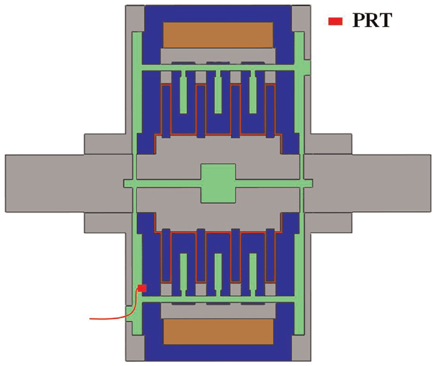
Installation of the PRT.
Figure 23 shows the temperature rise curves of the MDMRB. The temperature increments in stages 2–4 are 20.22, 6.10, and 2.61°C, respectively. It indicates that the temperature rise of the MDMRB is also affected by the initial braking velocity. Moreover, the temperature at the measuring point increases to 53.42°C at the end of the experiment with an increment of 31.98°C compared to the initial temperature. According to the transient temperature simulation values in Section 3.2, the maximum difference between the temperature at the measuring point and the internal highest temperature can reach up to 30°C. Therefore, the maximum temperature value of the MDMRB is estimated to be near 85°C during the entire experimental process, which is far lower than the maximum allowable operating temperature of the chosen MRF (130°C).
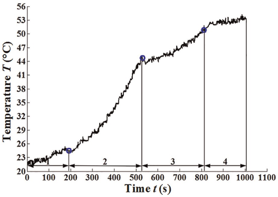
Temperature rise curves of the MDMRB.
4.5 Velocity following characteristic
The velocity following experiment is presented to explore the ability of the MRB to follow the established velocity which made the output velocity follow the set velocity-time curve. In this section, the braking experiment was conducted to discuss the relationship between the average deceleration of the MDMRB and the current, and the coil current was increased from 0.1 to 2.1 A successively, with increments of 0.1 A. By fitting a polynomial to the data of the braking experiments, the numerical relationship between the average braking deceleration and the coil current can be expressed as

Furthermore, the coil current is regulated by the duty ratio of the control board output during the braking process. Moreover, in the braking experiments, the numerical relationship between the duty ratio and the coil current is measured, and a polynomial is fitted to the data of the experiments. The relationship between coil current and duty ratio can be expressed as

Four different target velocity curves are utilized for the velocity-following experiments. As illustrated in Figure 24, the corresponding target input current can be deduced by combining the target velocity function with equation (17). Then, the velocity-following experiments with the target input current to control the MDMRB. During the experiments, the real-time velocities of the rotating shaft were collected and recorded by sensors. The actual output velocity of the MDMRB compared with the target velocity is shown in Figure 25. Although the actual braking velocity fluctuates during vehicle braking, it basically obeys the variation tendency of the target velocity. The inconsistency may be induced by several factors including the stability of the output torque of the MDMRB, the time delay of the coil current, as well as the fitting error of the relationship equation between the average deceleration and the coil current.
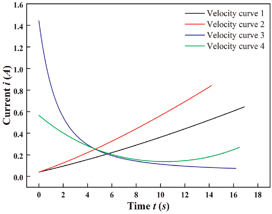
Target current versus braking time.
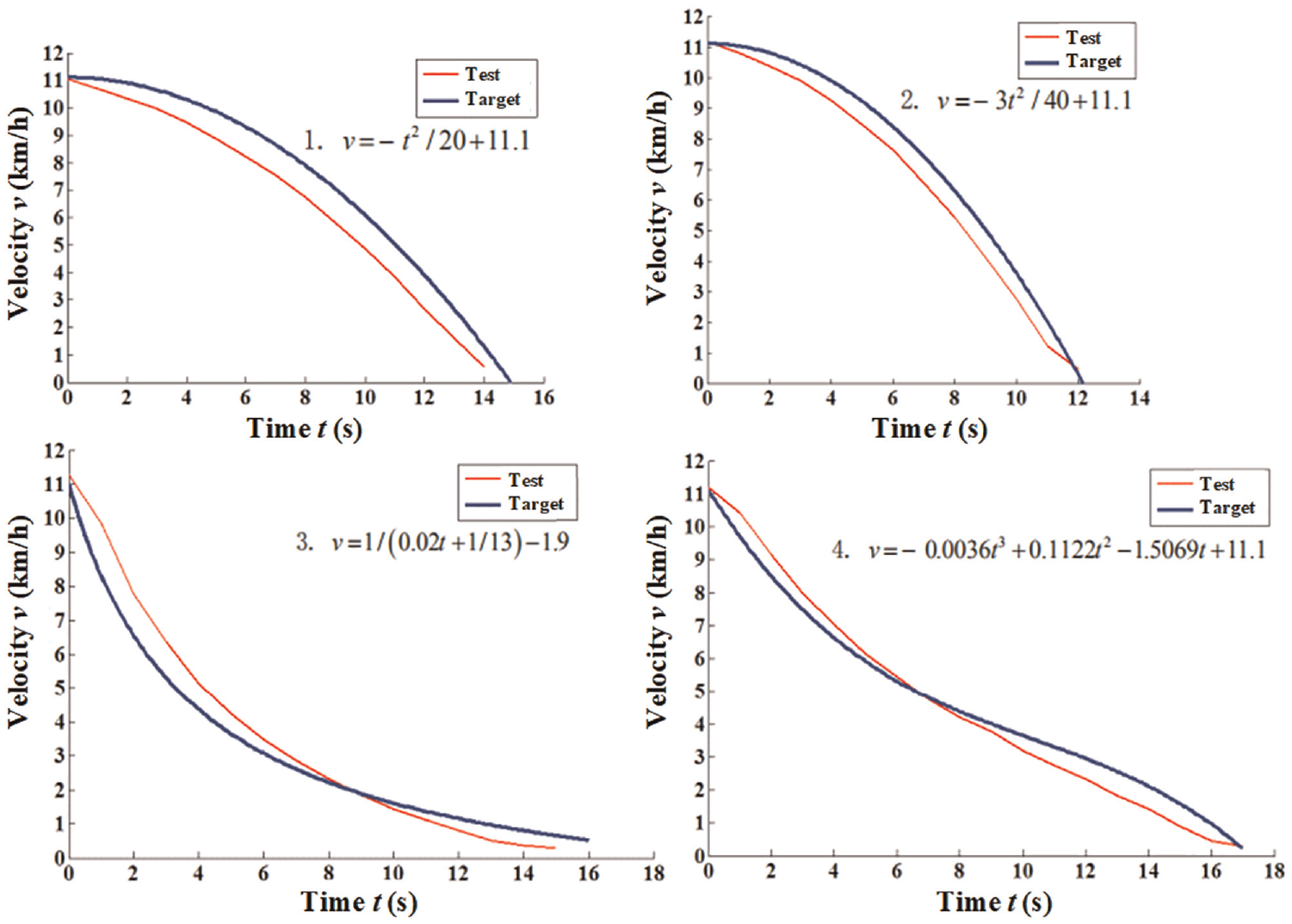
Comparative diagram of actual velocity following different target velocities.
5. Conclusion
In this paper, an MDMRB for A00-class minicars was proposed and comprehensive theoretical analysis, finite element simulation and experimental verification were performed to evaluate the MDMRB. Simulation results indicate that the output braking torque of the MDMRB can reaches up to 263.86 Nċm with an input current of 3 A, which can fully satisfy the design requirements. Moreover, the maximum internal temperature is estimated to be near 85°C, below the maximum allowable operating temperature of the MRF. The no-load torque output experiments present that the viscous resistance changes synchronously with the vehicle velocity. During the braking process, the fluctuations of the deceleration and the output torque are negligible for a constant current. Moreover, the braking torque accords with the linear relationship with the coil current for a constant initial braking velocity. Energy conversion during the entire vehicle braking causes the internal temperature of the MDMRB to increase from 21.44 to 53.42°C. The response time of the braking torque, which increases with the value of the coil current, is about 200 ms for the MDMRB prototype. Additionally, the MDMRB possesses very desirable velocity-following characteristics. Consequently, simulation and experimental results indicate that the MDMRB exhibits excellent braking characteristics.
However, the experimental evaluation in this paper still has some shortcomings that heavy-load and extreme braking conditions have not been taken into account. Therefore, future works should focus on various complex operating conditions including heavy-load, adhesion coefficient of the roads and higher initial braking velocity. Moreover, further optimization is necessary to improve the reliability and shorten the response time of the MDMRB.
Footnotes
Declaration of conflicting interests
The authors declared no potential conflicts of interest with respect to the research, authorship, and/or publication of this article.
Funding
The authors disclosed receipt of the following financial support for the research, authorship, and/or publication of this article: This work was supported by the National Natural Science Foundation of China (Grant No. 52175047) and the Anhui Provincial Natural Science Foundation (Grant No. 2008085ME140).