
Abstract
A finite element model of shrouded blades is established to analyze the vibration responses due to the impact between adjacent blades. In the finite element model, the blade and the shroud are simulated using beam element and lumped mass, respectively. On the basis of the finite element model, a beam–beam impact model is developed to study the vibro-impact responses of shrouded blades. By comparing the natural frequencies and vibration responses, the finite element model is verified by an analytical model. In addition, a test rig is also set up to compare the results obtained from simulation and experiment, and the influences of different parameters such as shroud gap, excitation amplitude, and excitation frequency on the vibro-impact response are analyzed by finite element model and experiment. The results obtained from finite element model and experimental model indicate that the impacts between adjacent shrouded blades weaken with the increase of the shroud gaps and excitation frequency, and the vibro-impact responses between shrouded blades become strong with the increasing excitation amplitude. The results also show that the second-order flexural vibration of blade is easier to be excited and the super-harmonic resonance phenomenon closed to the second-order flexural natural frequency is more significant than that at other flexural natural frequencies. The reason is that the position of the external force applied on shrouded blade accords with its second-order flexural vibration mode.
Introduction
The impact with clearance is a very common dynamic phenomenon in mechanical system, such as shrouded blades1,2 and gear systems, 3 which can cause the complicated nonlinear vibration characteristics, and many researchers1,2,4–6 have discussed the dynamic characteristics of vibro-impact system with clearance theoretically and experimentally. Many mathematical models were proposed to describe the dynamic phenomena of vibro-impact systems, such as lumped mass models,7–15 beam-stop impact models,2,4,6,16–22 and beam–beam impact models,1,5,23,24,28 which enriched the research results of vibro-impact system with clearance.
Based on lumped mass model,7–15 some scholars have analyzed the nonlinear dynamic characteristics of vibro-impact system. Banerjee et al. 7 studied the nonlinear grazing bifurcation characteristics of an impact system by experiment, and their results indicated that the narrow band of chaos could appear under the grazing conditions. Santhosh et al. 8 established a single degree of freedom (DOF) model under constant and variable normal loads to investigate the nonlinear dynamic phenomena of turbine shrouded blade with impact and friction. Jiang and Wiercigroch 9 investigated the grazing bifurcation characteristics of an oscillator with one-sided constraint. Based on experimental and semi-analytical methods, Ing et al. 10 discussed the nonlinear dynamic phenomena of a hard impact system near-grazing condition, and they found that the instantaneous jumps between periodic bifurcation and chaos could appear due to the effects of grazing. Luo and Xie 11 studied the bifurcation characteristics of a vibro-impact system, and their results showed that Hopf bifurcation could appear in the system under some appropriate parameters. Elmegård et al. 12 established a single DOF model using analytical method to simulate a cantilever beam with two-sided constraints, and the nonlinear dynamic responses agreed well with the experimental results, especially for small amplitude solutions. Andreaus et al. 13 established a dynamic model of a soft impact bilinear oscillator, and analyzed the nonlinear vibration responses by bifurcation diagrams, Lyapunov coefficients, return maps, and phase portraits. Andreaus et al. 14 simplified a cantilever beam as an equivalent single-degree-of-freedom model or an equivalent multiple-degree-of-freedom model and studied the non-smooth dynamics of the system subjected to a transverse harmonic force and impact onto a soft obstacle.
As the research continued, beam models are widely adopted to consider the effects of higher order modes16,17 and many researchers also adopted beam model to simulate the beam-stop impact responses.18–25 Bureau et al. 18 proposed an experimental method with feedback control which can analyze the nonlinear bifurcation characteristics of a vibro-impact system, and the typical nonlinear dynamic phenomena like coexisting stable and unstable solution were observed in the experimental results. The impact characteristics between steel ball and cantilever beam were analyzed through finite element and experimental methods in Pang et al. 19 and Qin and Yin. 20 Herrera et al. 22 studied the nonlinear characteristics of a flexible beam system with impact. Andreaus et al. 25 studied the microcantilever dynamics in tapping mode atomic force microscopy by using a multimode approximation and analyzed some response features at nominal impact and contact between cantilever tip and sample surface, focusing on how they depend on the cantilever being excited at first or second resonance.
Besides the vibro-impact analysis of simple impact dynamic model, the vibro-impact responses of beam–beam impact model also attracted a lot of interests.1,5,26,27 On the basis of Euler–Bernoulli beam theory, the nonlinear dynamic characteristics of shrouded blade with clearance impact were analyzed, 1 and the authors extended their researches to analyze the similarities and differences of the two impact models, beam-stop impact model, and beam–beam impact model, in shrouded blade impact systems. 26 Andreaus et al. 28 studied the soft-impact dynamics between a beam and a rod and analyzed the impact-induced complicated nonlinear vibration responses under a harmonic excitation of the beam built-in base.
In above researches, analytical or semi-analytical models are mainly adopted. Except for these models, finite element method is also used to establish the dynamic models of beam-type structures or other more complicated blade structures.5,27–36 Knudsen and Massih 33 established a finite element model (FEM) of a Bernoulli-type beam with springs, and analyzed the vibro-impact response of the system with loose supports under a harmonic load. Krishna and Padmanabhan5,34 established the FEMs of blades, and studied the vibration responses of the flexible beam undergoing vibro-impact with two other flexible beams at its free end, and discussed the steady state characteristics of the beams near the first and second modes, and verified the numerical simulation results by experiment.
In this study, a beam–beam impact model is developed to analyze the impact dynamic responses of shrouded blade system using finite element method and experimental method, and the super-harmonic resonance caused by impacts are focused on. Moreover, vibration responses obtained from FEM are also verified by those obtained from analytical model (AM) and experiment. The structure of this paper is as follows. After this part, experimental model (EM) and FEM of the shrouded blade system with clearance impact were introduced in the next second section. The effectiveness of FEM is verified by comparing the natural frequencies obtained from experiment and AM in the third section, and the harmonic response and vibro-impact response are compared with those from AM in this part. In fourth section, the vibration responses under different system parameters are studied numerically and experimentally. Finally, the main conclusions are given in the final section.
EM and FEM
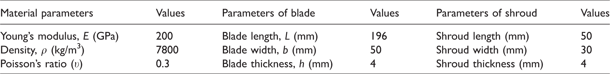
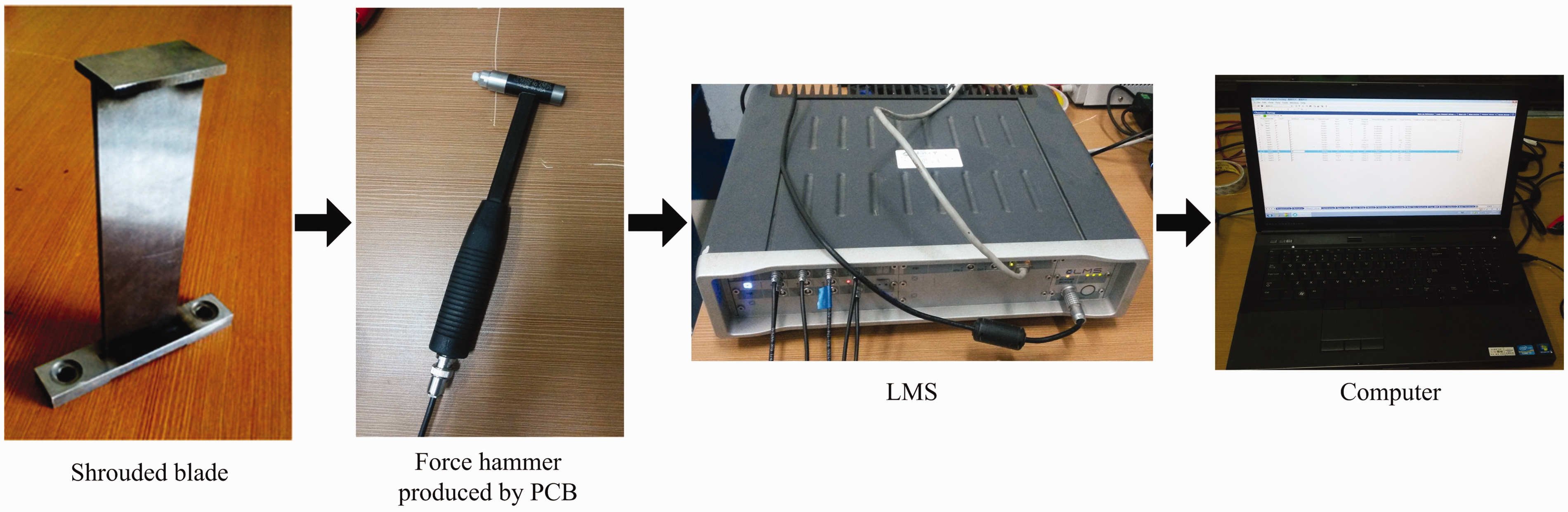
The experimental set-up of the shrouded blade with clearance impact is shown in Figure 1. As is shown in Figure 1, the excitation source is provided by the shaker, and LMS data acquisition system is used to collect the acceleration signal and force signal obtained by the acceleration sensors and force sensor. The acceleration sensors are placed on the two shrouds, and the force sensor is placed on excitation position of the blade, respectively. Figure 2(a) shows the schematic of experimental set-up, while the FEM of the experimental set-up is depicted in Figure 2(b) where the shrouded blade accompanying with excitation source is called “active blade” and the other one is called “passive blade”. In the FEM, the two blades are divided into 100 beam elements with 101 nodes, and the concentrated mass m1 is used to simulate the shroud mass and acceleration sensor, while the concentrated mass m2 is adopted to consider the effects of force sensor. The detailed parameters of the shrouded blade are listed in Table 1.
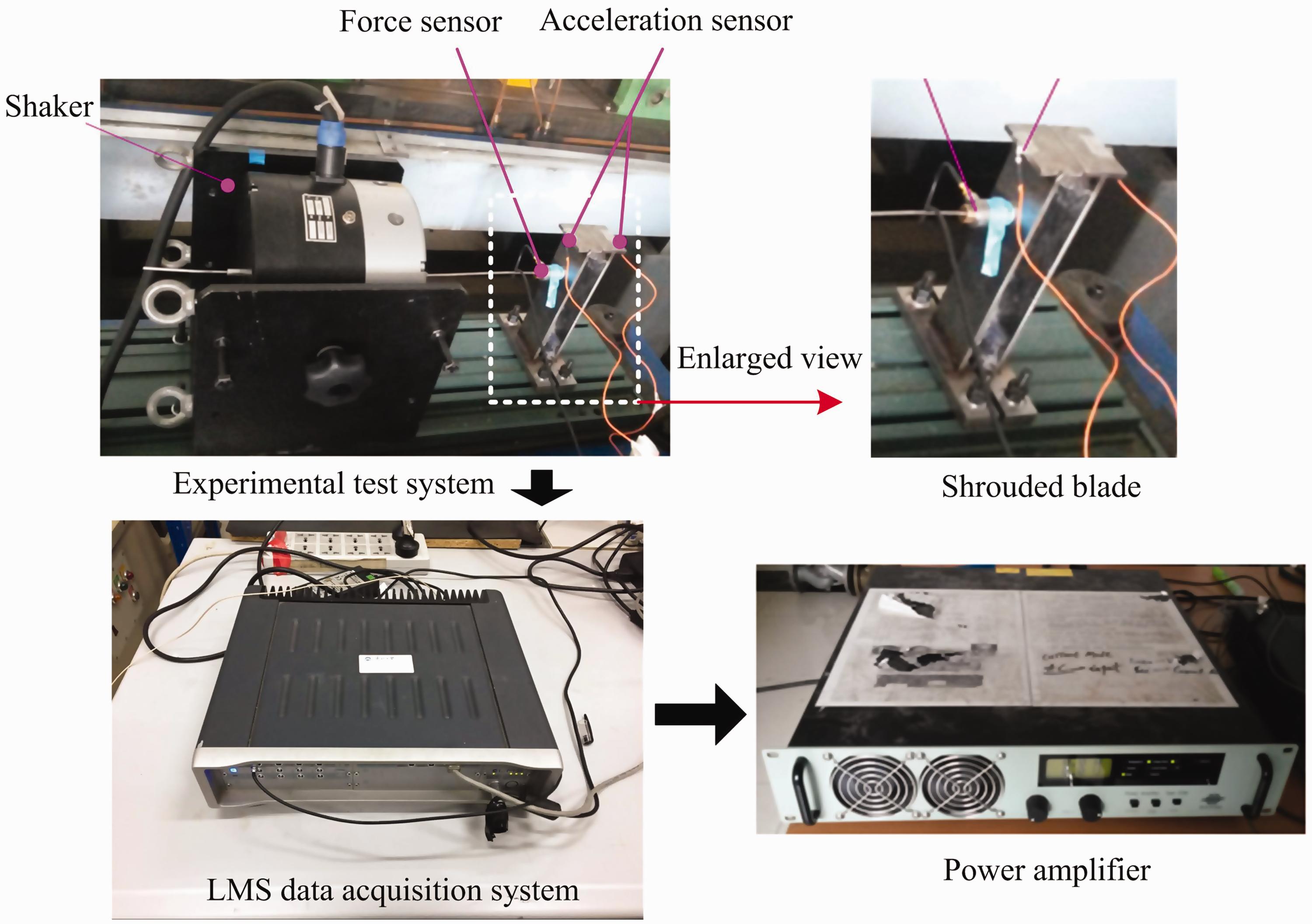
Experimental set-up of shrouded blade with impact.
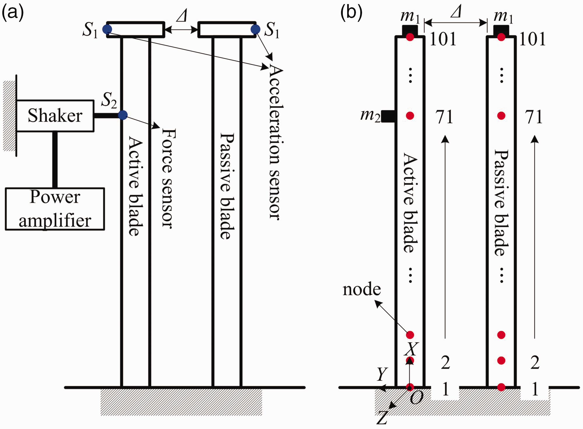
Schematic of experimental set-up and FEM: (a) schematic and (b) FEM.
Parameters of shrouded blade.
In this section, beam element with two nodes is used to develop the FEM of shrouded blade, and each node has six DOFs: three translational DOFs and three rotational DOFs (see Figure 3). The displacement vector 
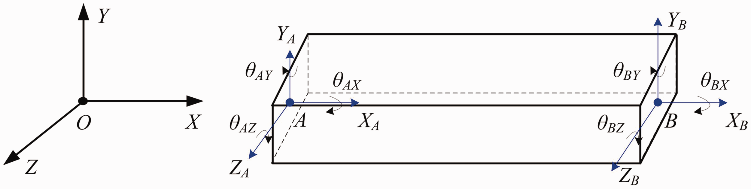
Schematic of beam element.
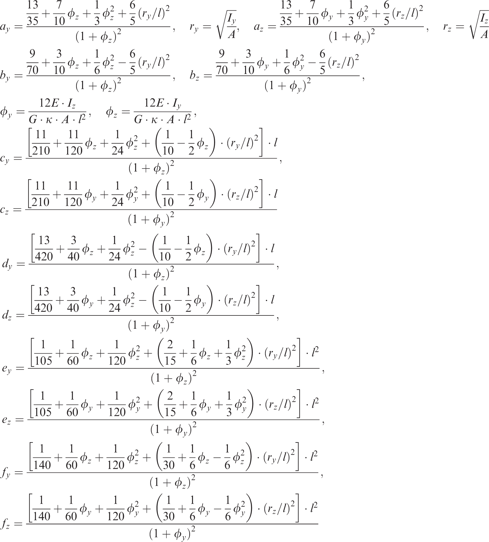
The mass matrix 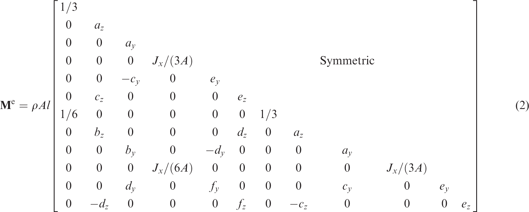
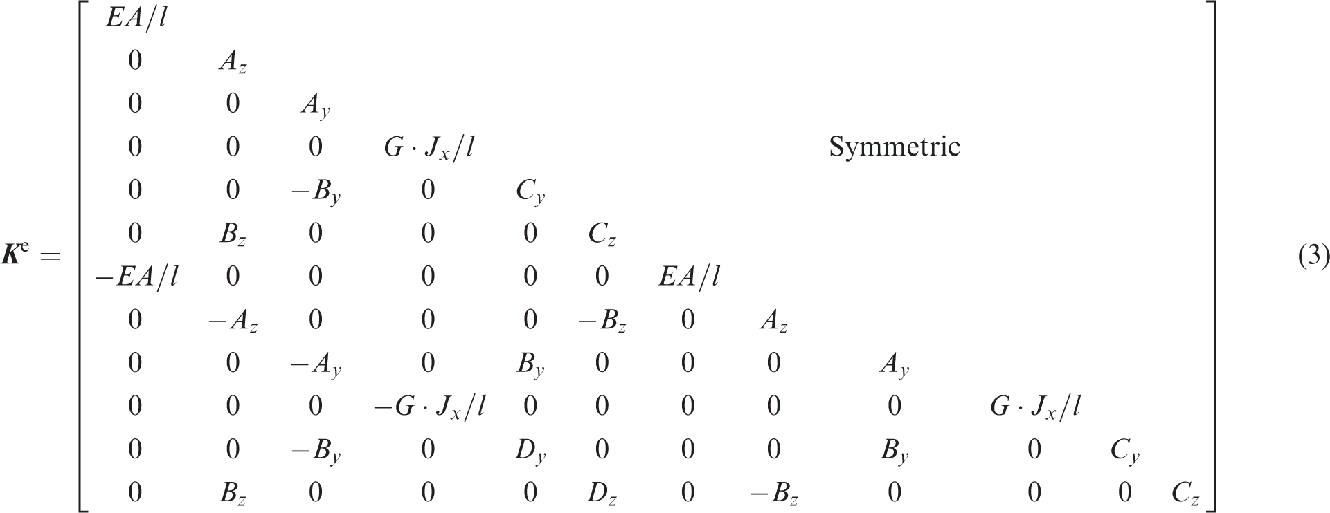
The stiffness matrix 
The FEM of the active blade can be expressed as


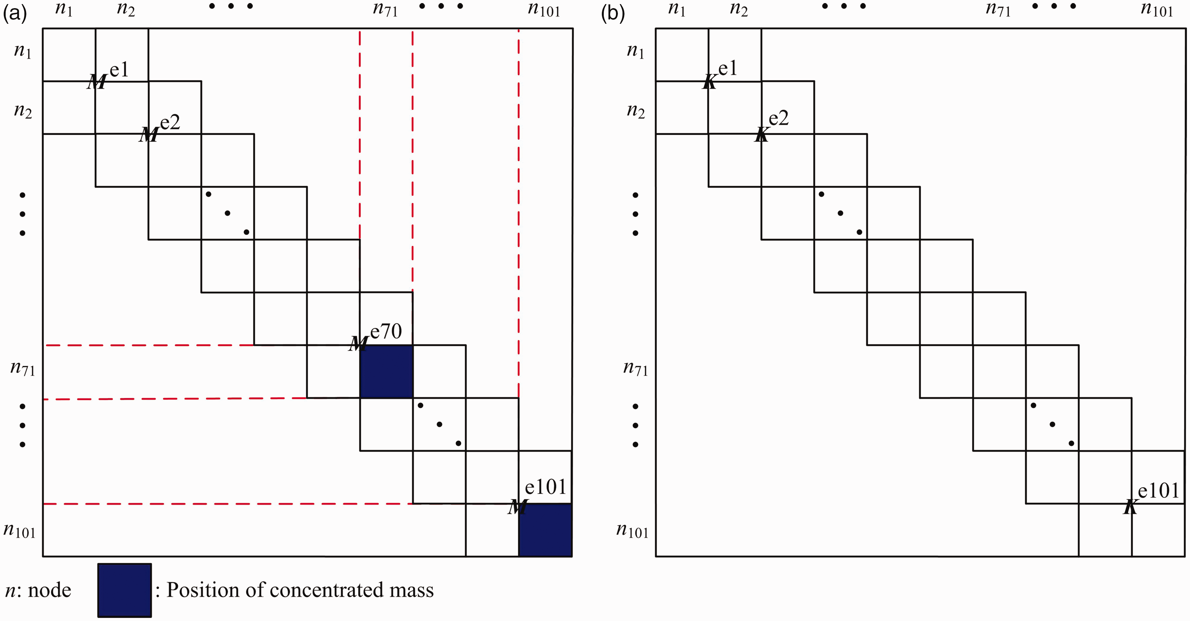
Schematic of the assmebling process of mass and stiffness matrices: (a) mass matrix and (b) stiffness matrix.
Model verification
In this section, FEM of the shrouded blade is firstly verified by comparing the natural frequencies obtained from FEM and experiment (see Figure 5). Measured frequency response curves of shrouded blade with and without considering the effects of force sensor are shown in Figure 6. In addition, an AM is also used to verify the correctness of the FEM. For the detailed modeling process of the AM refer Xie et al. 26 The first three flexural natural frequencies of FEM, AM, and EM with and without force sensor are listed in Tables 2 and 3, which show that the first three flexural natural frequencies obtained from FEM, AM, and EM agree well. The natural frequencies obtained from FEM and AM are a little bigger than that obtained from EM, and the potential reasons of the errors maybe that the rigid constraint at the blade root is adopted in FEM and AM, while the constraint in EM is provided by bolted connection. Obviously, the constraint stiffness during experiment is a little smaller than that used in FEM and AM, which can lead to the lower natural frequencies.
Schematic of the test system of the shrouded blade to measure the natural frequencies.
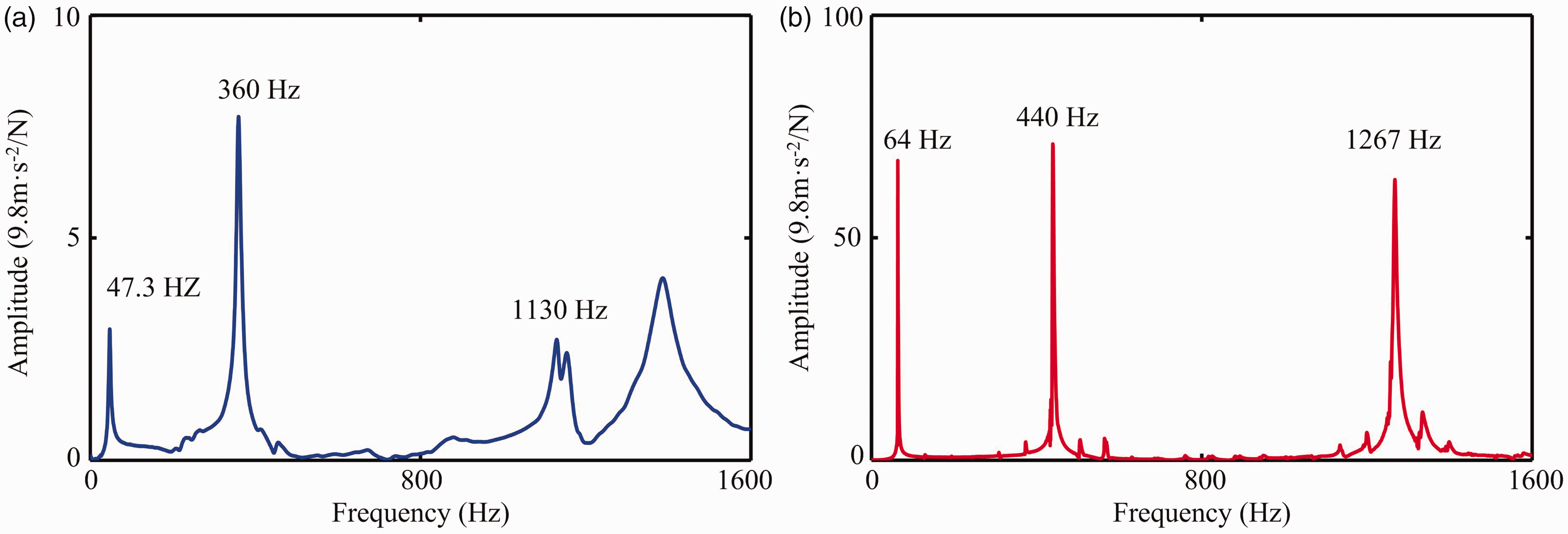
Measured frequency response function of shrouded blade: (a) with force sensor and (b) without force sensor.
The first three flexural natural frequencies obtained from FEM, AM, and EM with force sensor.
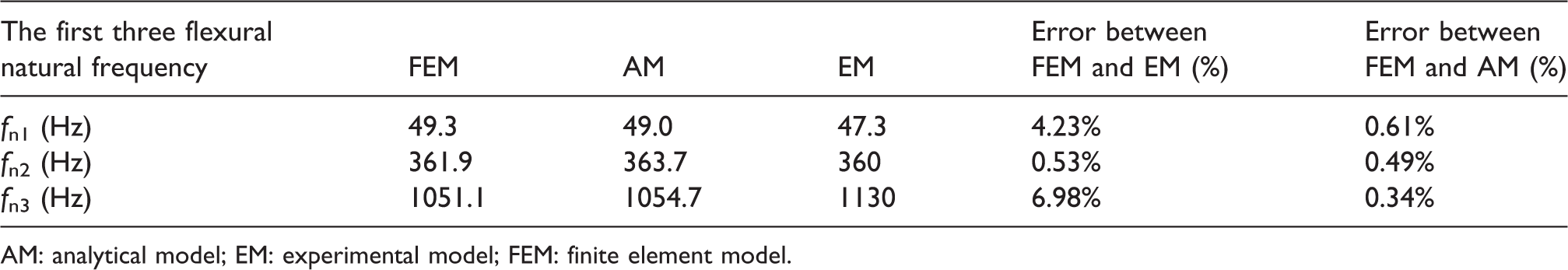
AM: analytical model; EM: experimental model; FEM: finite element model.
The first three flexural natural frequencies of FEM and EM without force sensor.
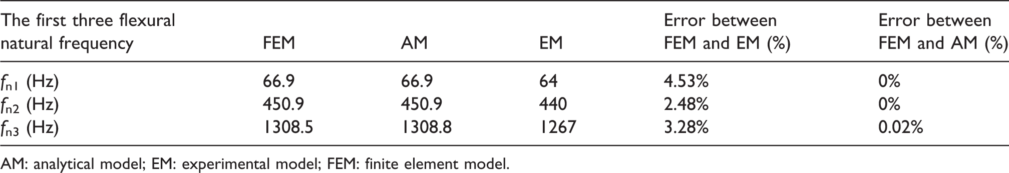
AM: analytical model; EM: experimental model; FEM: finite element model.
In order to further verify the proposed FEM, the harmonic responses obtained from AM and FEM were compared. When excitation force amplitude is set as F0 = 15 N, the amplitude–frequency response of shrouded blade with and without considering the effects of force sensor are shown in Figure 7. And the time-domain waveform at the excitation force frequency fe = 60 Hz and F0 = 15 N is shown in Figure 8. It can be seen from these figures that the vibration responses obtained from two models are in good agreement. Figure 9 shows the comparison of the FEM and AM vibration responses under shroud–shroud impact condition when F0 = 15 N, fe = 60 Hz, and Δ = 0.5 mm. It can be seen that both the time-domain waveforms and amplitude spectra are all in good agreement.
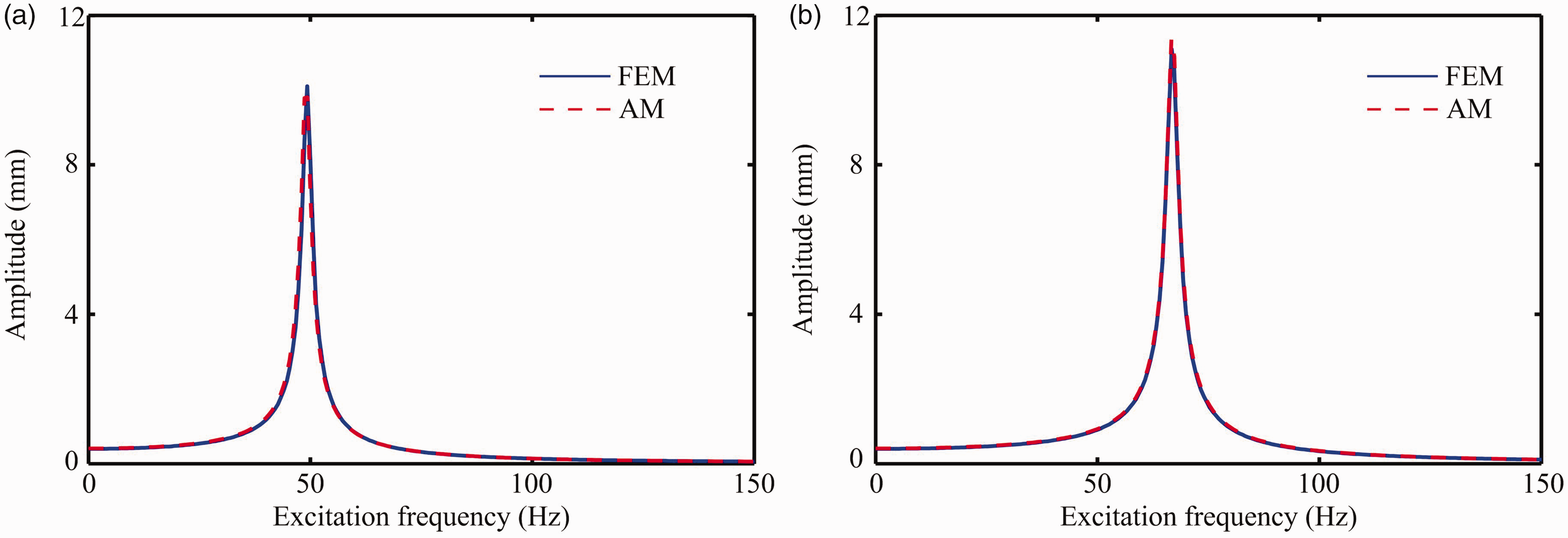
Amplitude–frequency responses of shrouded blade: (a) with force sensor and (b) without force sensor.
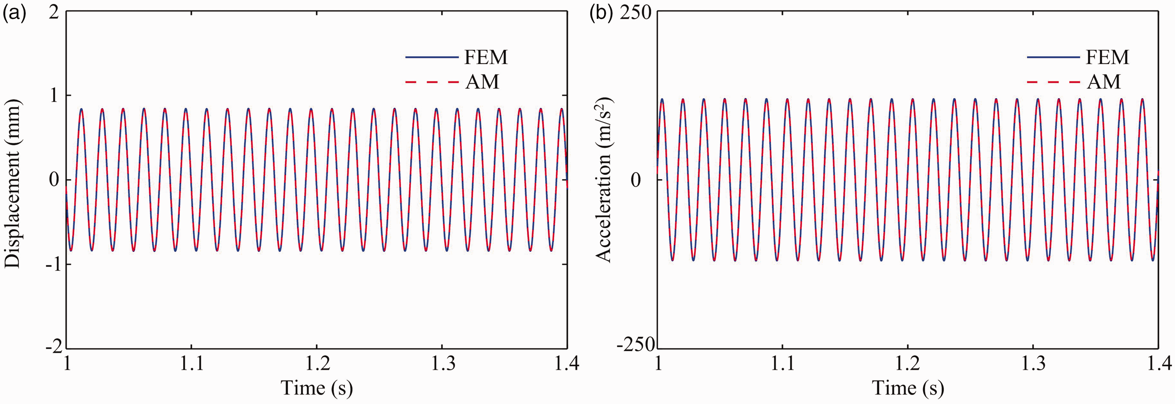
Responses of shrouded blade: (a) displacement time-domain waveform and (b) acceleration time-domain waveform.
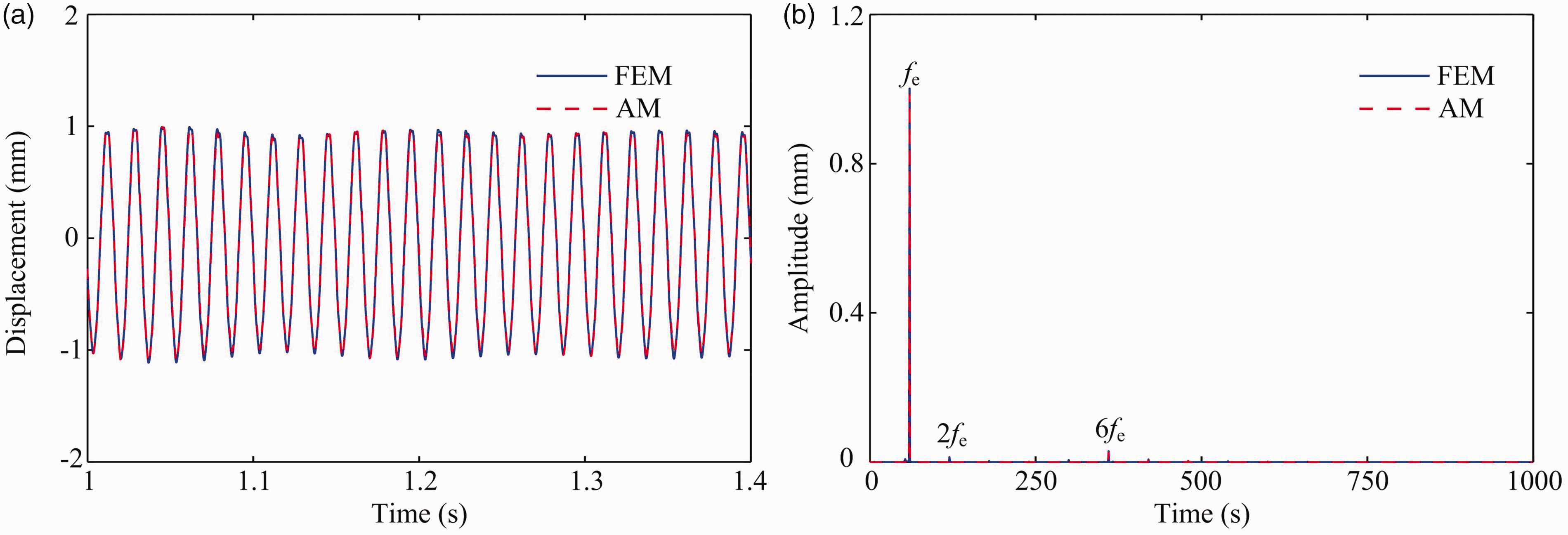
Vibro-impact responses: (a) displacement time-domain waveforms and (b) amplitude spectra.
Vibration responses of shrouded blade under different parameters
In this section, the vibro-impact responses of shrouded blade under different parameters such as shroud gap Δ, excitation force amplitude F0, and excitation frequency fe are analyzed numerically and experimentally.
Vibration response of shrouded blade under different shroud gaps
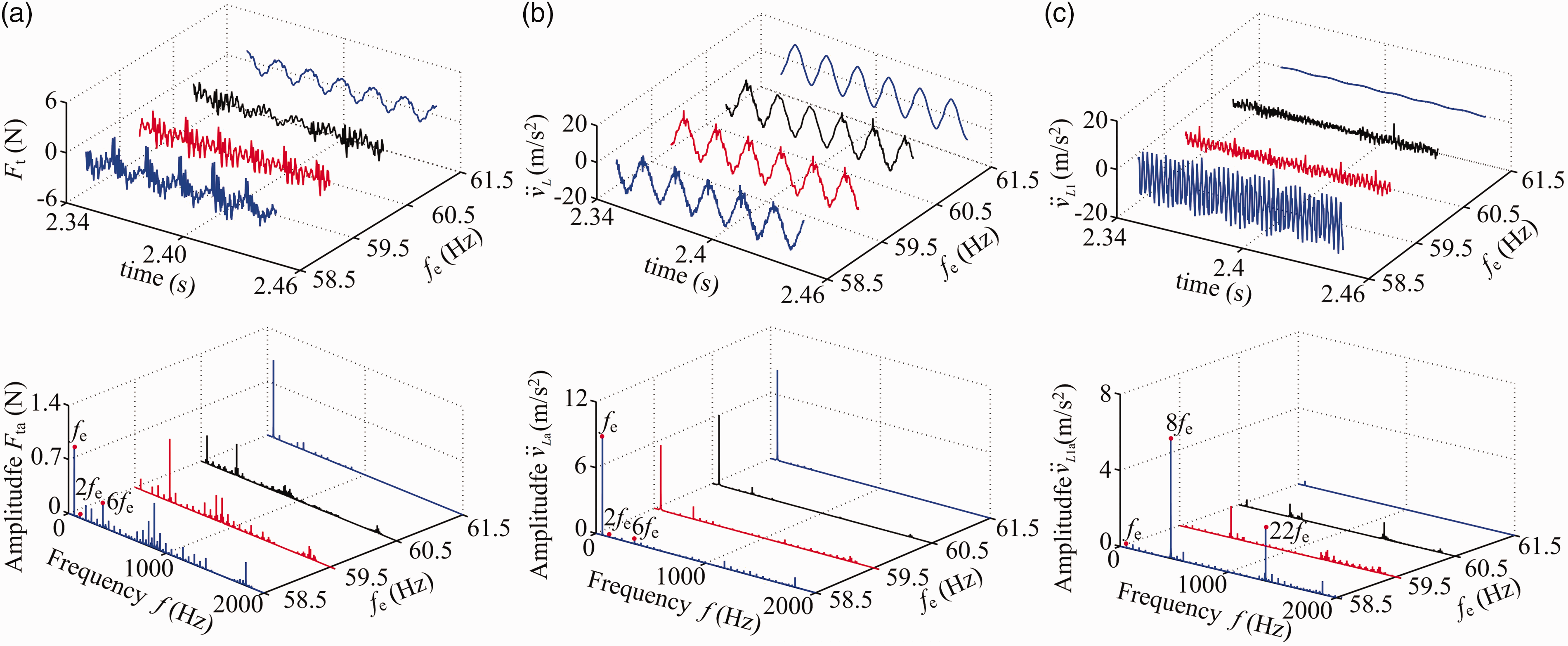
Taking the shroud gap Δ as variable parameter, and the other parameters are selected as: F0 = 15 N, fe = 60 Hz. Under different gaps, dynamic responses of shrouded blade obtained from EM and FEM are shown in Figures 10 and 11. These figures display that the vibro-impact responses between the shrouded blades decrease with the increase of shrouded gap, which is caused by the decreasing impact force (see Figures 10(a) and 11(a)). The frequency domain responses show that the amplitude amplification phenomena at 6fe for the active blade and at 8fe and 22fe for the passive blade can be observed. This is because the 6fe is closed to the second-order flexural natural frequency of active blade (see the natural frequencies with force sensor in Table. 2, fn2 = 361.9 Hz), and 8fe and 22fe are closed to the second- and three-order flexural natural frequency of the passive blade (see the natural frequencies without force sensor in Table 3). Moreover, the amplitude amplification phenomena for active blade at the second-order flexural natural frequency is more significant than that at other order flexural natural frequencies, the reason is that the second flexural vibration of active blade is easier to be excited because its external force loading position accords with its second flexural vibration mode (see Figure 12).
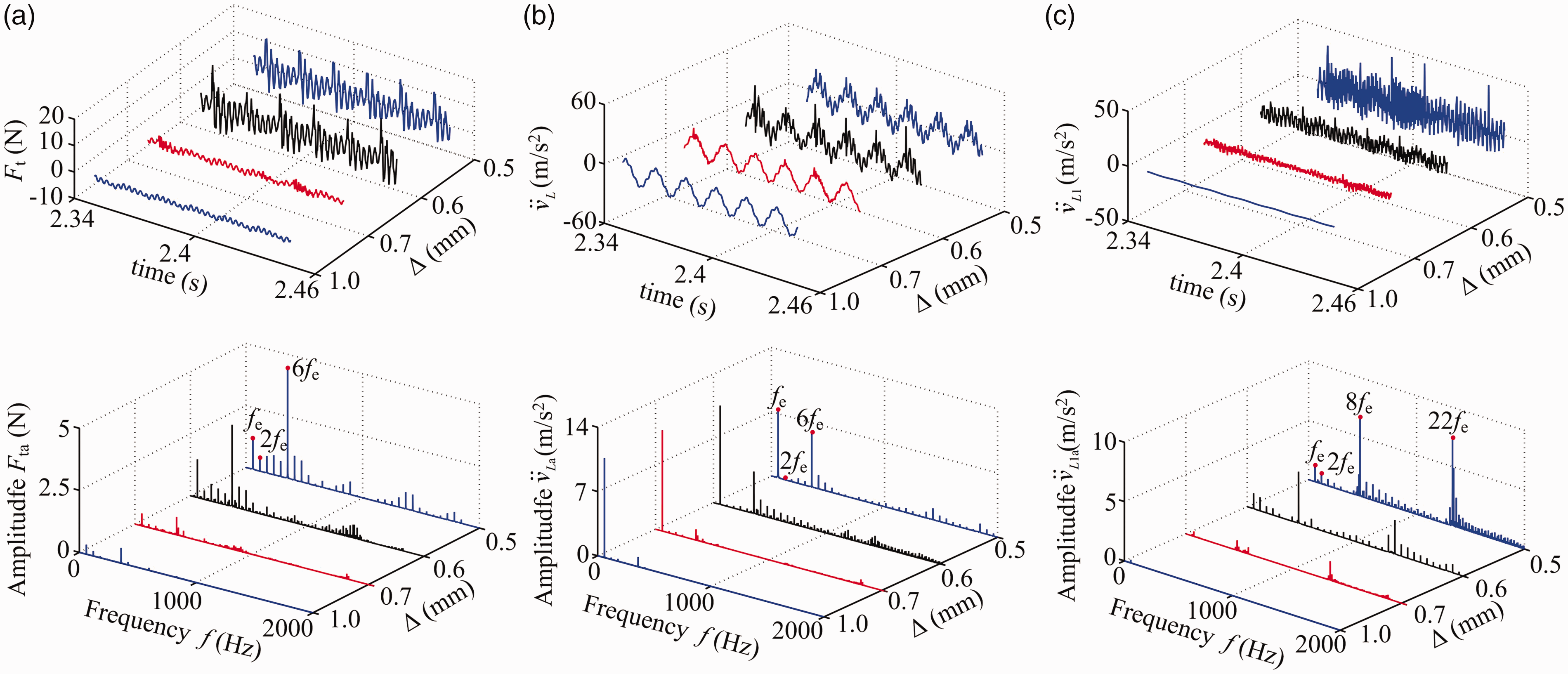
Vibro-impact responses obtained from EM under different gaps Δ: (a) force response, (b) acceleration response of active blade, and (c) acceleration response of passive blade.
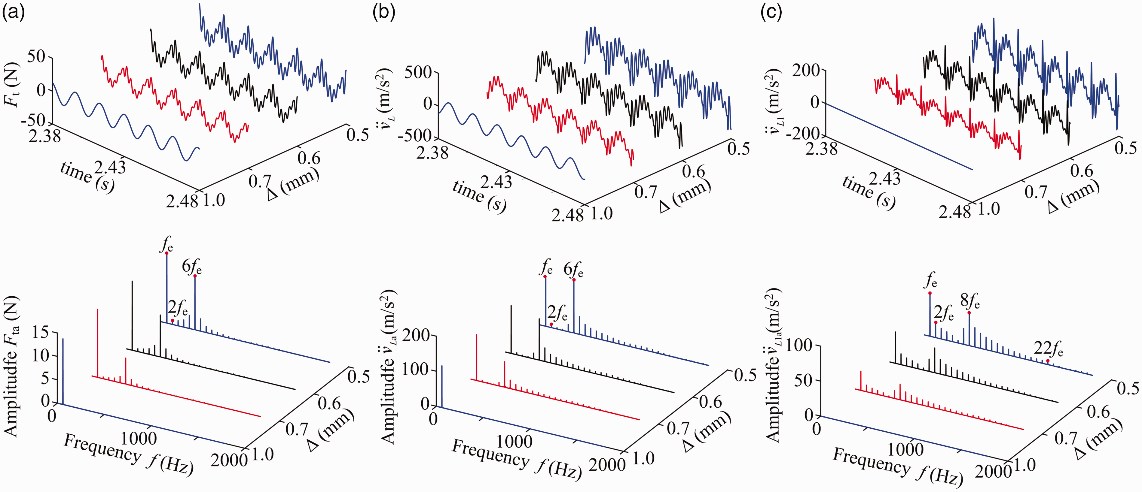
Vibro-impact responses obtained from FEM under different gaps Δ: (a) force response, (b) acceleration response of active blade, and (c) acceleration response of passive blade.
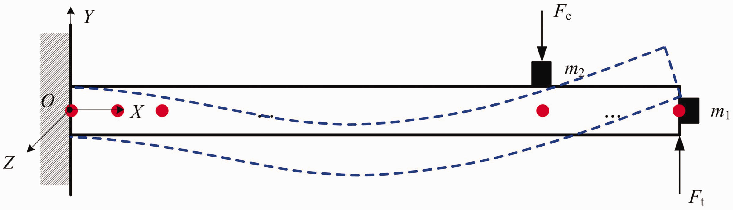
Schematic of the external force loading position on active blade.
Vibration response of shrouded blade under different excitation amplitudes
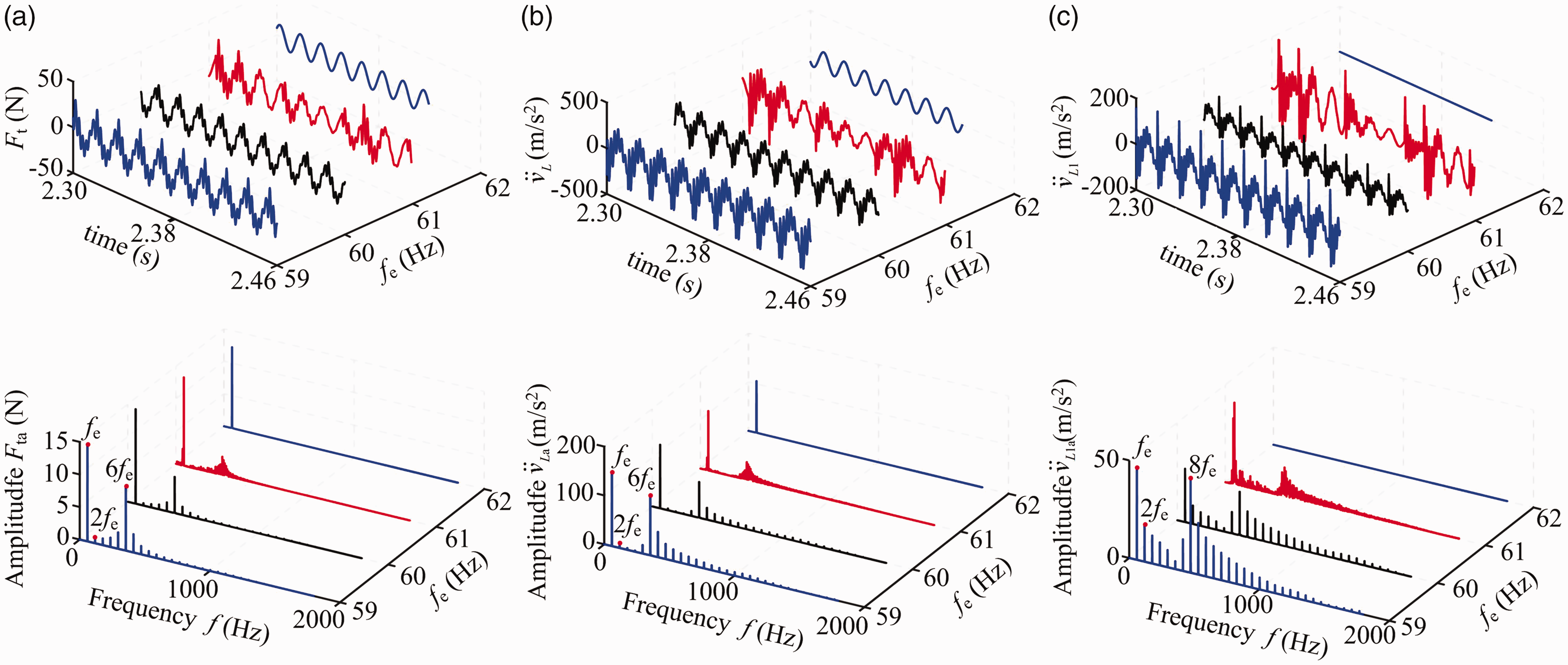
In this section, the vibration responses of shrouded blade under different excitation amplitudes are analyzed numerically and experimentally, and the other parameters are set as: Δ = 0.7 mm, fe = 60 Hz. Vibro-impact responses of shrouded blade obtained from EM and FEM are shown in Figures 13 and 14. Vibro-impact responses between shrouded blades become severe with the increasing excitation amplitude (see Figures 13(a) and 14(a)), which is opposite to that with the increasing shroud gaps. This is because the large excitation force amplitude can increase the flexural displacement of the shrouded blade, which intensifies the impact between the shrouds. Furthermore, the amplitude amplification phenomena at 6fe for the active blade and at 8fe and 22fe for the passive blade could also be observed; the excitation mechanism is the same as that under different shroud gaps.
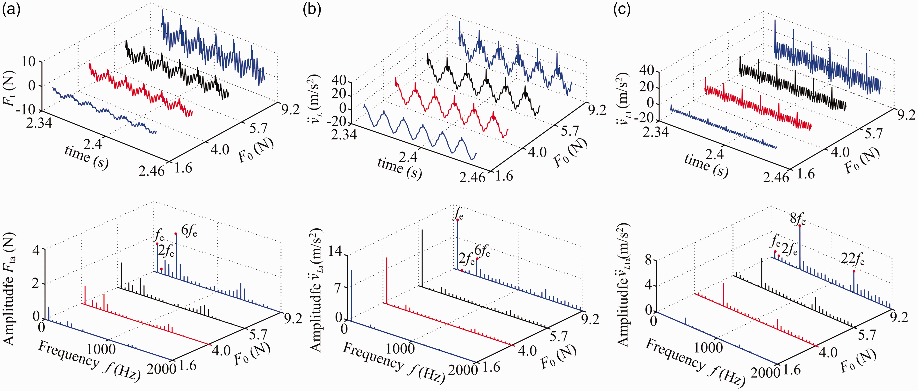
Vibro-impact responses obtained from EM under different excitation amplitudes F0: (a) force response, (b) acceleration response of active blade, and (c) acceleration response of passive blade.
Vibro-impact responses obtained from FEM under different excitation amplitudes F0: (a) force response, (b) acceleration response of active blade, and (c) acceleration response of passive blade.
Vibration response of shrouded blade under different excitation frequencies
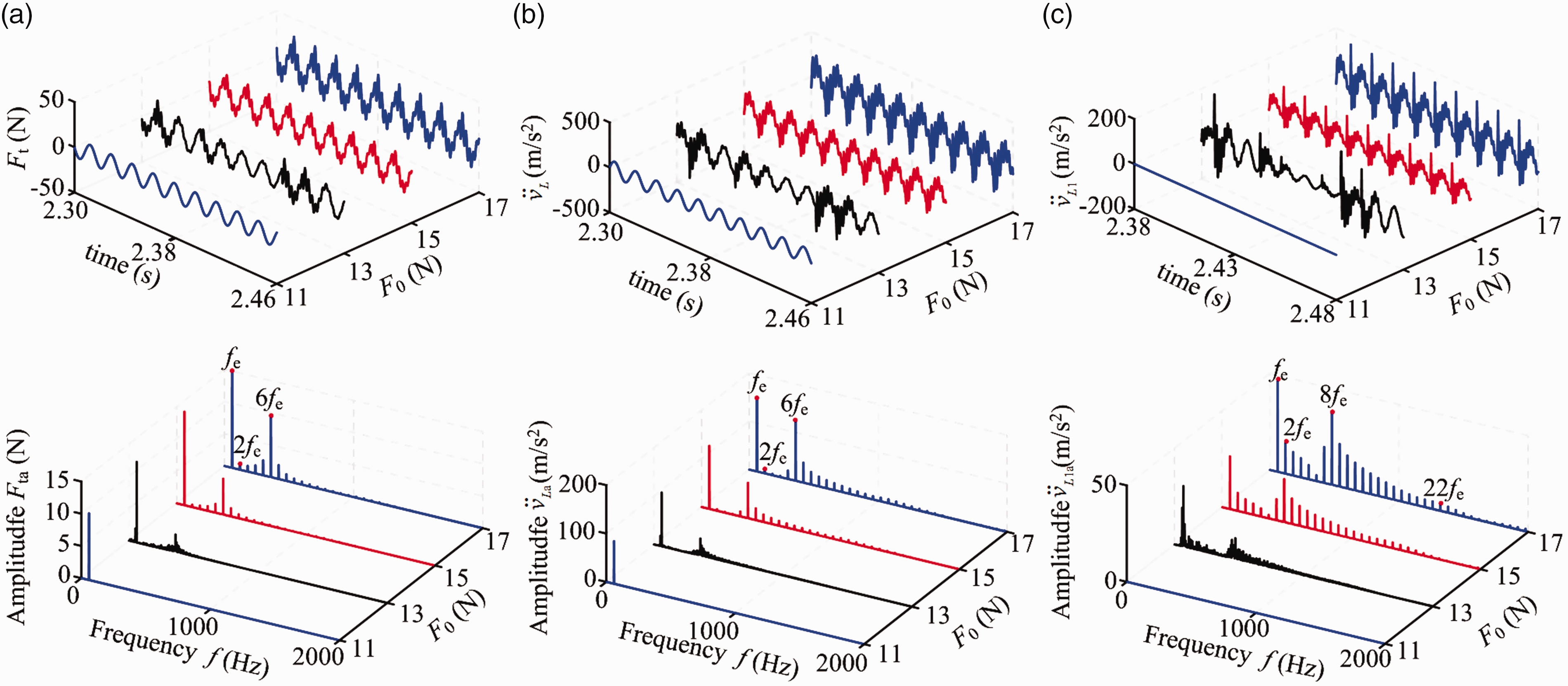
Taking the excitation frequency fe as variable parameter, and the other parameters are selected as: Δ = 0.7 mm, F0 = 15 N. Under different excitation frequencies, vibro-impact responses of shrouded blade obtained from EM and FEM are shown in Figures 15 and 16. These figures show that the vibro-impact responses between shrouded blades weaken and then the impacts between shrouded blades disappear with the increasing excitation frequency. This is because the excitation force frequency is far away from the resonance frequency with its increase. The similar amplitude amplification phenomena can also be observed (see frequency-domain graphs in Figures 15 and 16).
Vibro-impact responses obtained from EM under different excitation frequencies fe: (a) force response, (b) acceleration response of active blade, and (c) acceleration response of passive blade.
Vibro-impact responses obtained from FEM under different excitation frequencies fe: (a) force response, (b) acceleration response of active blade, and (c) acceleration response of passive blade.
Conclusion
This paper adopts FEM to simulate the shrouded blade and establishes a beam–beam impact model to analyze the vibro-impact responses of shrouded blade. The FEM of shroud blade is also verified by comparing with the natural frequencies, amplitude–frequency responses, and vibro-impact responses obtained from AM and experiment. In addition, the system vibration responses are also analyzed by numerical simulation and experiment under different gaps between shrouds, the amplitudes, and frequencies of excitation force.
The results obtained from FEM and experiment indicate that with the increase of the shroud gap and excitation force frequency, the vibro-impact responses between shrouded blades become weak, and the vibro-impact responses become strong with the increasing excitation amplitude. In addition, the super-harmonic responses close to the second-order flexural natural frequency are more significant than that at other flexural natural frequencies. This is because the loading positions of external force acted on shrouded blade can easily excite the second-order flexural vibration mode of shrouded blade.
Footnotes
Declaration of conflicting interests
The author(s) declared no potential conflicts of interest with respect to the research, authorship, and/or publication of this article.
Funding
The author(s) disclosed receipt of the following financial support for the research, authorship, and/or publication of this article: the National Natural Science Foundation (Grant no. 11772089), the Fundamental Research Funds for the Central Universities (Grant nos. N170308028, N160312001 and N160313004), Program for the Innovative Talents of Higher Learning Institutions of Liaoning (LR2017035) and Research Project of State Key Laboratory of Mechanical System and Vibration (Grant no. MSV201707).