
Abstract
In the present paper, a real-time implementation of a previously introduced nonlinear optimal-based vibration control method is presented. A vibrating structure, namely a wind turbine tower-nacelle laboratory model equipped with a tuned vibration absorber, is analysed. For control purposes, a magnetorheological damper is used in a tuned vibration absorber system. Force constraints of a magnetorheological damper are an intrinsic part of the implemented nonlinear technique. The aim of the current research is to experimentally investigate the influence of nonlinear optimal-based vibration control law quality index elements’ weights on the vibration attenuation effectiveness along with the magnetorheological damper stroke amplitude, maximum control current or force. As a reference, simple, optimal-based, modified ground-hook law with the sole control objective of primary structure deflection minimisation is used in addition to the passive systems with constant magnetorheological damper current values, proving the benefits of the proposed solution.
Keywords
Introduction
Vibrations may become a crucial problem for slender systems and structures such as towers, masts, chimneys, wind turbines,1–7 bridges,8,9 high buildings,10,11 plate structures,12,13 etc. Most of them are equipped with vibration attenuation or fatigue reduction solutions.
The concepts utilised to mitigate vibrations include tuned vibration absorbers (TVAs), tuned liquid (column) dampers, viscoelastic/hydraulic dampers, granular dampers, piezoelectric actuators, etc.14,15 TVAs are widely used vibration reduction solutions. A standard (passive) TVA consists of an additional moving mass, a spring and a viscous damper, the parameters of which are tuned to the selected (most often first) mode of the vibration. 16 Passive TVAs work well at the load conditions characterised with a single frequency but cannot adapt to a wide excitation spectrum. 3 During the system/structure operation lifetime, its frequency spectra may vary; thus, more advanced TVA solutions are investigated to enable TVA tuning to the vibration frequency.
Another approach that may be used to cope with the vibration problem is the deployment of high strength and fatigue-reducing material technologies, throughout which nanotechnology seems one of the most promising. Copper nanoparticles can help to reduce the unevenness in the surface of the steel, which in turn reduces the amount of stress risers, limiting fatigue cracking. The addition of nanoparticles can help to solve the brittleness issue of the welds and improve the fracture problems associated with high strength bolts. Nano-aluminium-oxide of high purity improves the tensile and flexural strength of the concrete. Carbon nanoreinforments as well as nano-silica are also used to improve the concrete strength, with the latter increasing its resistance to water penetration too; nano-iron gives self-sensing capabilities along with improved compressive and flexible strengths. Zirconia nanocomposites exhibit superior physical (strength, hardness, and flexibility) and chemical endurance. The use of nano-coatings can result in higher corrosion and fire resistance, and also in self-cleaning capabilities.17,18 These exemplary novel material solutions contribute to the increased lifespan of slender structures, due to the mechanism of nano-scale strength, hardness, and flexibility,19,20 along with their smart-maintenance. On the other hand, there are several concerns related to nanotechnology, including high cost (vibration absorbers are less expensive and highly effective) as well as health and environmental hazards.
Instead of dealing with the sophisticated materials for vibration and fatigue minimisation, the current paper focuses on the advanced vibration absorbers. Among them, magnetorheological (MR) TVAs are placed,5,6,11,21,22 as an MR damper guarantees a wide range of resistance force in comparison with a viscous damper and a high operational robustness along with minor energy requirements as compared with the active systems.1,3,22–28 Simulations and experiments show that the implementation of an MR damper in the TVA system may lead to further vibration reduction with regard to passive TVA.5,6
Most of the MR damper real-time control algorithms are based on the bang–bang approach or two-stage concepts with the calculation of an MR damper required force and precise force tracking algorithms.9,22,29 The latter concepts suffer from the inability to produce the demanded MR damper force pattern due to, e.g. the impossibility to generate active forces and force value limitations: lower constraint imposed by the residual force and upper constraint imposed by the piston velocity and maximum MR damper current/magnetic circuit saturation. As a result, the force pattern calculated at the first stage is not the same at the output of the second stage. Moreover, some advanced first-stage algorithms need real-time frequency determination which may be an issue for polyperiodic or random vibrations.30
Recently, an entirely different concept was proposed 30 – all of the MR damper force constraints are assumed to be an intrinsic part of a control method. This requires the utilisation of nonlinear control techniques, which include maximum principle-based methods,4,13,31 control Lyapunov function-based methods 8 including backstepping,10,32 (feedback) linearization methods / linear optimal control theory based on the Riccati equation solution,10,33 etc. Along with the advantages, each of the method groups have their disadvantages, that are significant for the current control problem consideration and solution.30
The concept which real-time implementation is presented in the paper was originally developed for the vibration attenuation of systems/structures equipped with MR TVAs, 30 from among which, a wind turbine tower-nacelle system is investigated currently in particular, using its scaled model.34–37 Wind turbines undergo external loads that vary in time, including wind load variations, wind shear, Karman vortices, the blade passing effect, differences in inflow conditions for each of the blades, sea waves and/or ice load, etc., as well as rotating elements’ unbalance, all of them contributing to the structural vibration and fatigue wear of towers and blades. The problem of wind turbine tower vibration was addressed within the scope of the Department’s research projects – a specially developed tower-nacelle laboratory model was built, assuming that a nacelle, a hub, a shaft, a generator, blades and possibly a gearbox are all represented by the rigid body fixed to the top of the vertical rod, representing a tower. The laboratory test rig gives the possibility to model tower vibrations under various aerodynamic, hydrodynamic, mechanical unbalance, changeable electromagnetic loads, etc., excitation sources – the horizontal concentrated force generated by a dedicated shaker may be applied at different heights of the rod, or at a nacelle position. Two initial bending modes of the vibration may be analysed; however, only the first one is investigated here and the MR TVA is tuned to its frequency. With the use of the MR damper, dedicated control solutions may be realized in comparison with the passive systems with constant MR damper current values.
The paper is organised as follows. First, a regarded system is depicted. Subsequently, the nonlinear optimal control problem is formulated and solved. Then, the implementation technique, the experimental setup and the test conditions are described. The paper is summarized with the real-time control results and several conclusions.
A regarded system
A wind turbine tower-nacelle model is considered as a primary vibrating system, which first bending mode (modal) mass is m1, (modal) stiffness is k1 and (modal) damping is c1. A TVA of mass m2, stiffness k2 and damping c2 is considered (Figure 1). The movement of both m1 and m2 is restricted to be linear displacement x1 and x2 (respectively) along the common axis (horizontal in Figure 1) of an applied excitation force
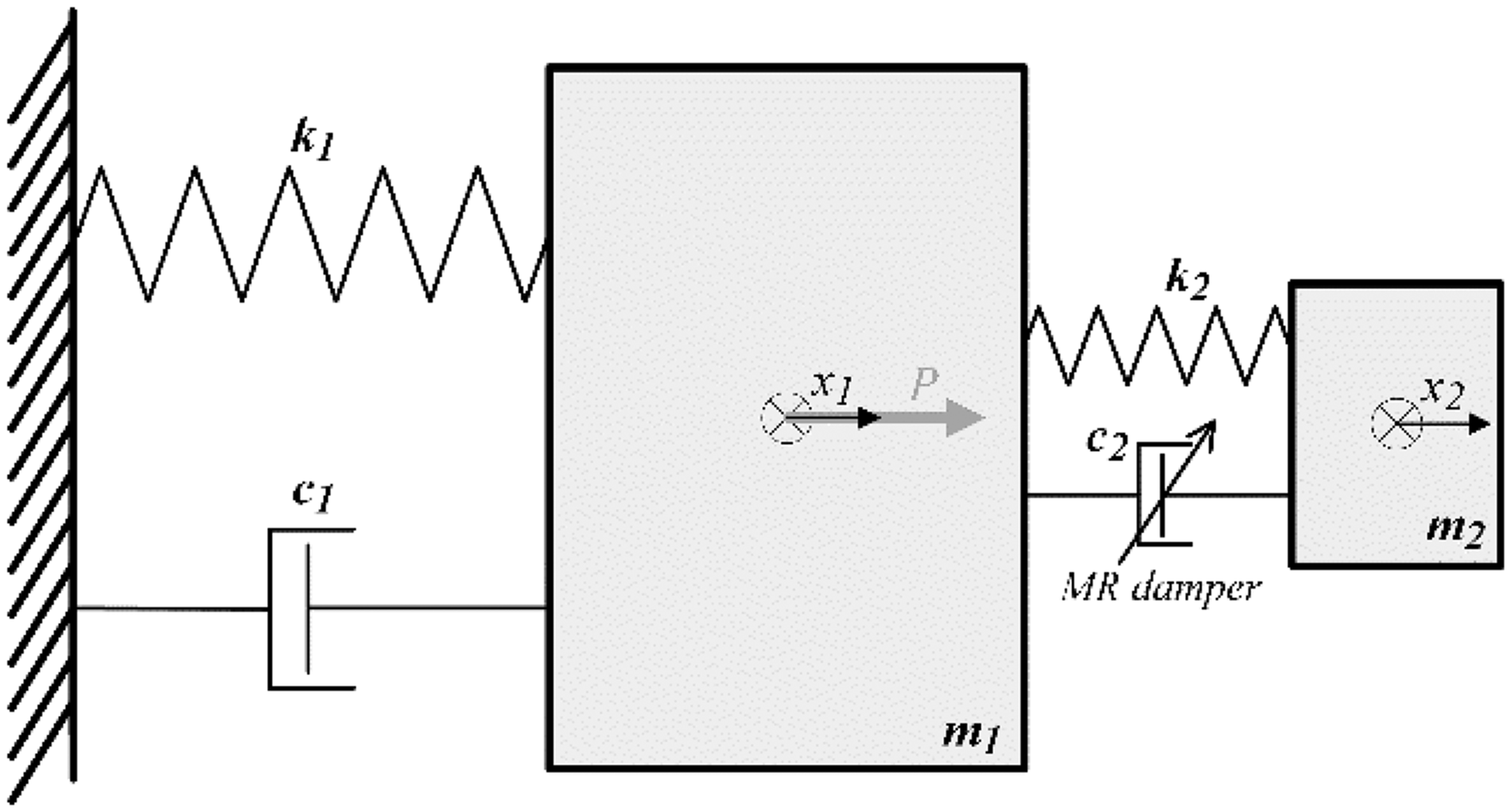
Two-body diagram of a regarded system with an MR TVA.
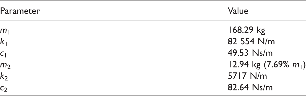
The adopted system parameters.
Problem formulation and solution
Consider the equation of a vibrating system with an MR TVA


Following ‘A regarded system’ section, assume: 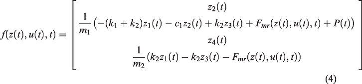

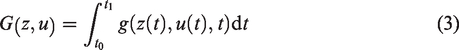
The considered quality function is
Assume the Hamiltonian in the form

If 


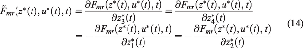


The Hamiltonian maximisation condition
39
is

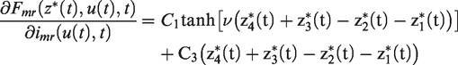
For the assumed 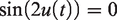
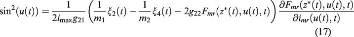
Analogically to Martynowicz
30
The implementation technique
The common approach to optimal control of nonlinear systems is offline computation of the optimal control
Regarding the above considerations concerning uncertain systems, the boundary value problem (1)(3)(8)÷(10) may be solved for every sample period of a real-time implementation. Due to the high computational load required online, the optimisation horizon may be assumed to be equal to one integration step; however, this also requires performance data acquisition, computation and control (DAC) environment when dealing with complex nonlinear systems. Utilising the MATLAB/Simulink environment, the bvp4c iterative scheme based on the three-stage Lobatto IIIa collocation formula 40 may be used for an efficient solution of the implicit nonlinear boundary value problems. Alternative iterative approaches are the Adomian decomposition method (ADM), the variational iteration method (VIM), 41 the homotopy analysis method (HAM) 42 and the homotopy method coupling with the perturbation technique – the homotopy perturbation method (HPM), 43 etc. HAM provides a family of solution expressions in the auxiliary parameter (even if a nonlinear problem has a unique solution). The auxiliary parameter gives an additional way to adjust the convergence region and rate of solution series; however, there are no rigorous theories to choose the auxiliary conditions. 44 In contrary, HPM uses the auxiliary parameter as a small parameter, and only few iterations are needed, unlike HAM where an infinite series is necessary. 45 Similar to HPM, VIM produces rapidly convergent successive approximations without the restrictive assumptions. It has been widely employed due to its flexibility, convenience and accuracy. Regarding the original VIM method, 41 many additional merits have been discovered and some advancements are suggested.46,47 Thus, VIM and HPM methods can effectively solve a large class of nonlinear problems including those with strong nonlinearity; they do not impose the limitations or assumptions required in classical perturbation methods, while they can overcome the difficulties arising in handling the ADM and HAM methods.45,48,49
Recently, a numerical implementation of one-step nonlinear optimal control for systems with MR TVAs was realised with MATLAB/Simulink dedicated level-2 s-function and bvp4c algorithm; 30 it was also shown that iteration procedures implicating large computational loads may be omitted, utilising very short time range basis optimal problem tasks with a high-frequency resetting function and zero initial conditions for all co-state integrators. In such a case, it was demonstrated that the influence of the transversality condition (10) error was negligible for the regarded MR TVA(s) control application.30 Thus, a real-time implementation of nonlinear optimal-based vibration control, with all of its advantages (including the various possible elements of the quality index), using simple DAC environment is possible.
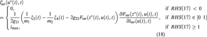
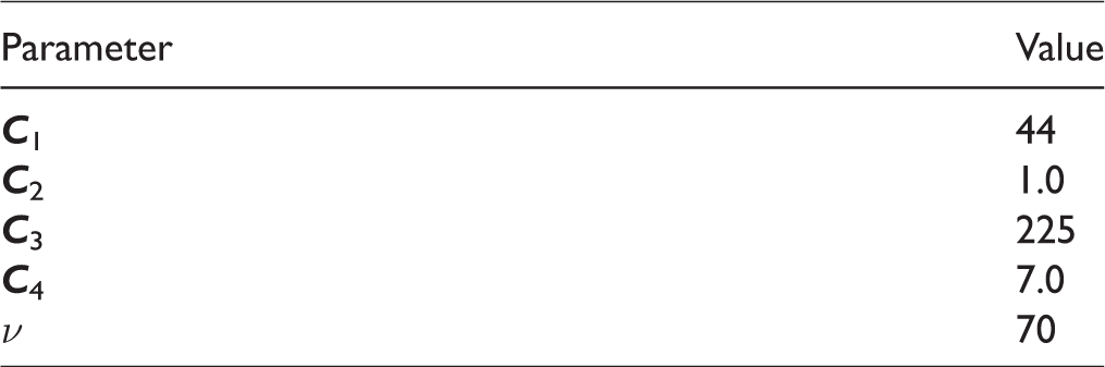
For the purpose of the real-time control of the wind turbine tower-nacelle model first bending mode, the approach described in the ‘Problem formulation and solution’ section and in ref.30 was implemented. The system and the initial MR damper model parameters as in Table 1 and Maślanka et al. 38 were used along with the MR damper control current formula (18) (this solution is further designated by Opt4). After the completion of the identification of the particular MR damper unit used, hyperbolic tangent model (5) parameters were modified accordingly (see Table 2) and utilised for the verified algorithm version, designated further by Opt7, being the basis for the analysis of various control cases I–IV (see ‘The test conditions’ section).
The identified MR damper model parameters.
A modified two-level displacement ground-hook law (Mod.GND) – the simple implementation of the optimal control for the case when primary system/structure displacement amplitude minimisation is the sole objective5,6,30 – was additionally tested during the present experimental study. This control law switches the control current between 0 and
The experimental setup
The analysed wind turbine tower-nacelle laboratory model had to fulfil various constraints imposed by the laboratory facility and project limitations. It was assumed that at least a partial dynamic similarity (similarity of motions of tower tips) between a real-world wind turbine tower-nacelle system (Vensys 82) and its scaled model has to be fulfilled.34,35,37 The absorber mass
The test rig (Figure 2) consists of a vertically oriented titanium alloy circular rod (no. 1, representing the wind turbine tower) and a system of steel plates (no. 2, representing the nacelle-assembly including the turbine) fixed to the top of the rod, with the MR TVA embedded. The titanium rod is rigidly mounted to a steel foundation frame (no. 3). The MR TVA is an additional mass (no. 4) moving horizontally along linear bearing guides, connected with the assembly representing the nacelle via springs (no. 5) and RD-1097–1 MR damper (no. 6) in parallel. The MR TVA operates along the same direction as the vibration excitation applied. The structure is excited by the TMS2060E lightweight electrodynamic shaker (no. 7 (TMS 50 )), the force of which is applied to the system of steel plates (no. 2) modelling the nacelle with the help of the drive train assembly (no. 8) of the changeable leverage.
The DAC system consists of a laser transducer for the nacelle-assembly displacement (i.e. the tower deflection)
The test conditions
The test conditions parameters are as follows. The wind turbine tower-nacelle model is excited by a harmonic force of amplitude minimise the primary structure deflection (nacelle-assembly displacement) minimise additionally the MR damper stroke amplitude: minimise additionally the MR damper current: minimise additionally the MR damper force:
While the MR damper current or force minimisation was not regarded as one of the primary quality objectives (i.e. control cases I and II), continuous current limitation
Real-time control results
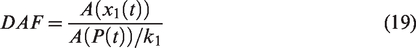
The efficiency of the adopted solutions is analysed using the frequency characteristics of the dynamic amplification factor (DAF)
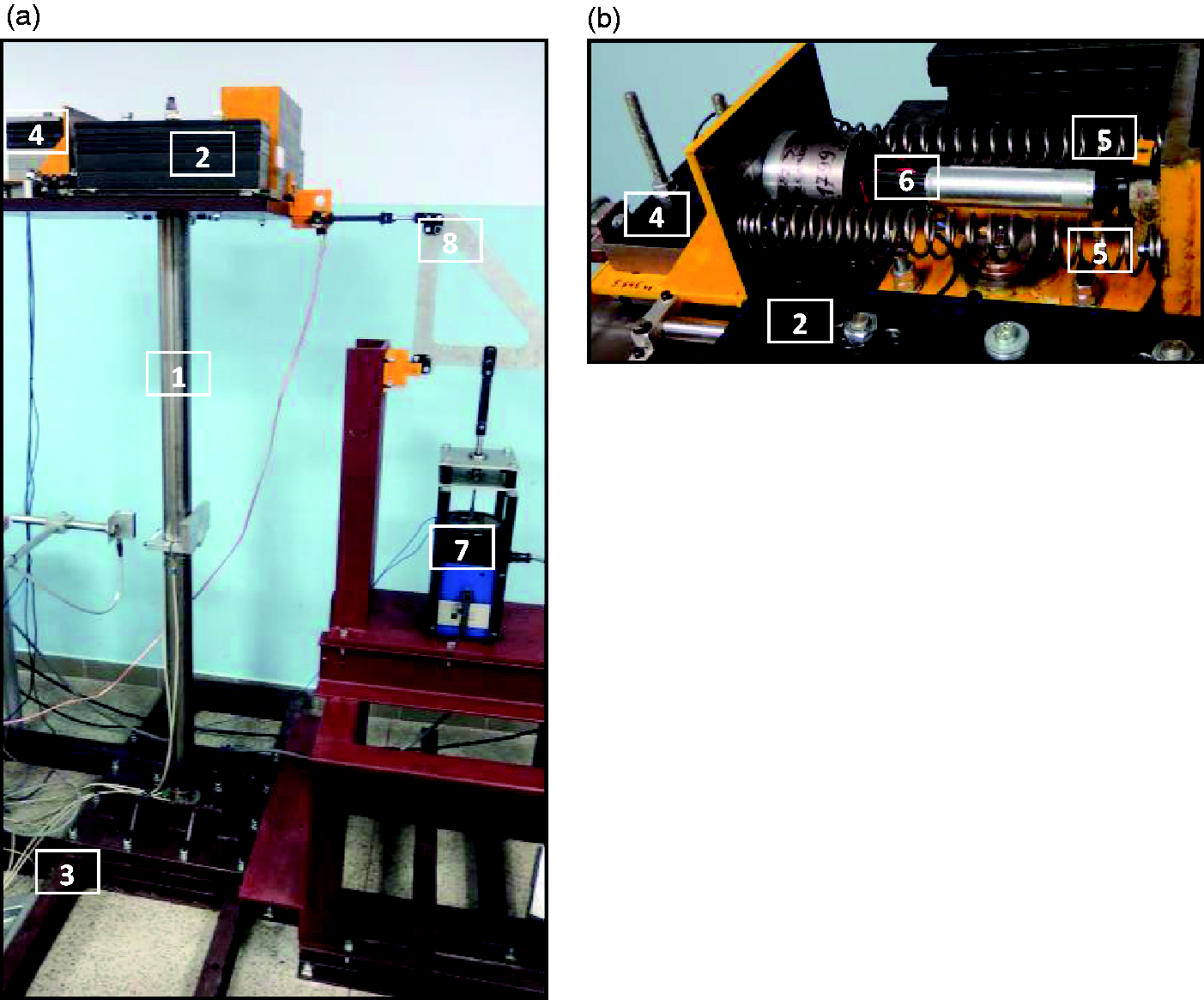
The laboratory test rig: (a) a general view, (b) the MR TVA.
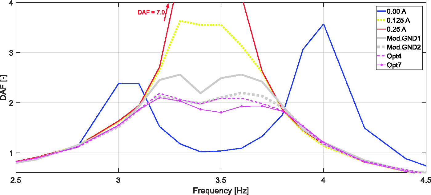
Dynamic amplification factor DAF frequency characteristics: passive system vs. Mod.GND1&2 vs. Opt4&7.
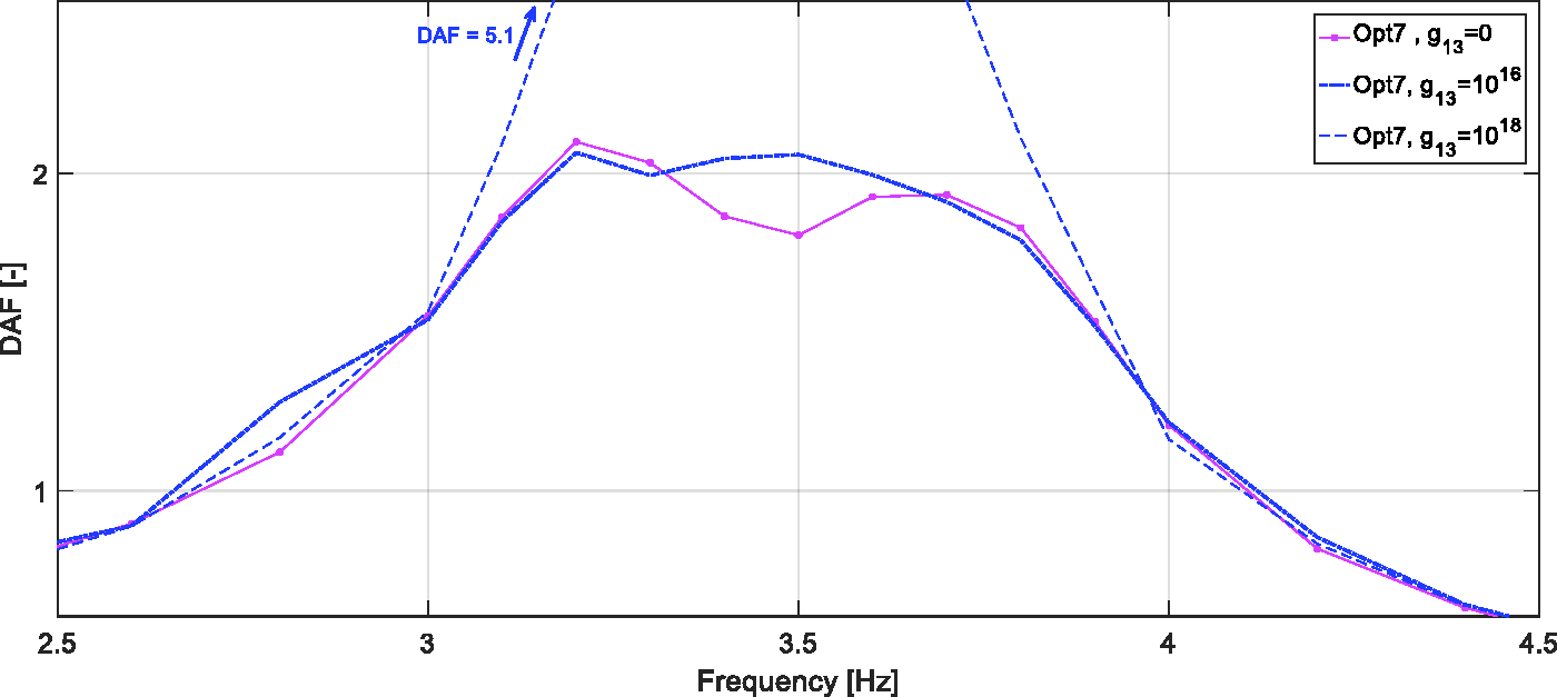
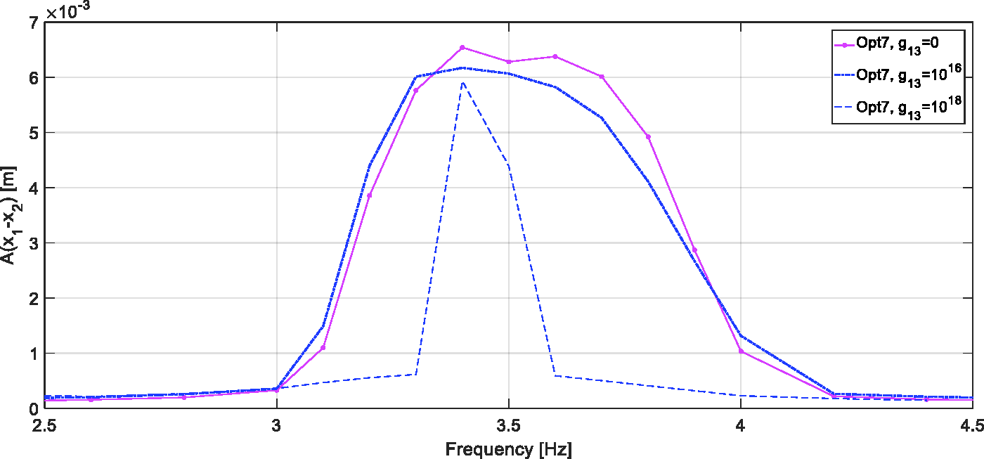
Dynamic amplification factor DAF frequency characteristics: Opt7 for different
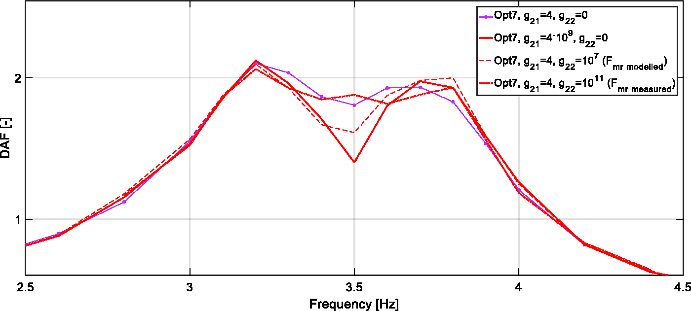
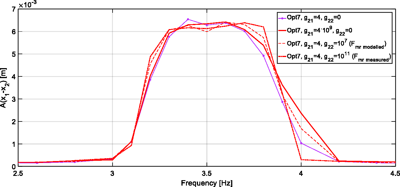
Dynamic amplification factor DAF frequency characteristics: Opt7 for different
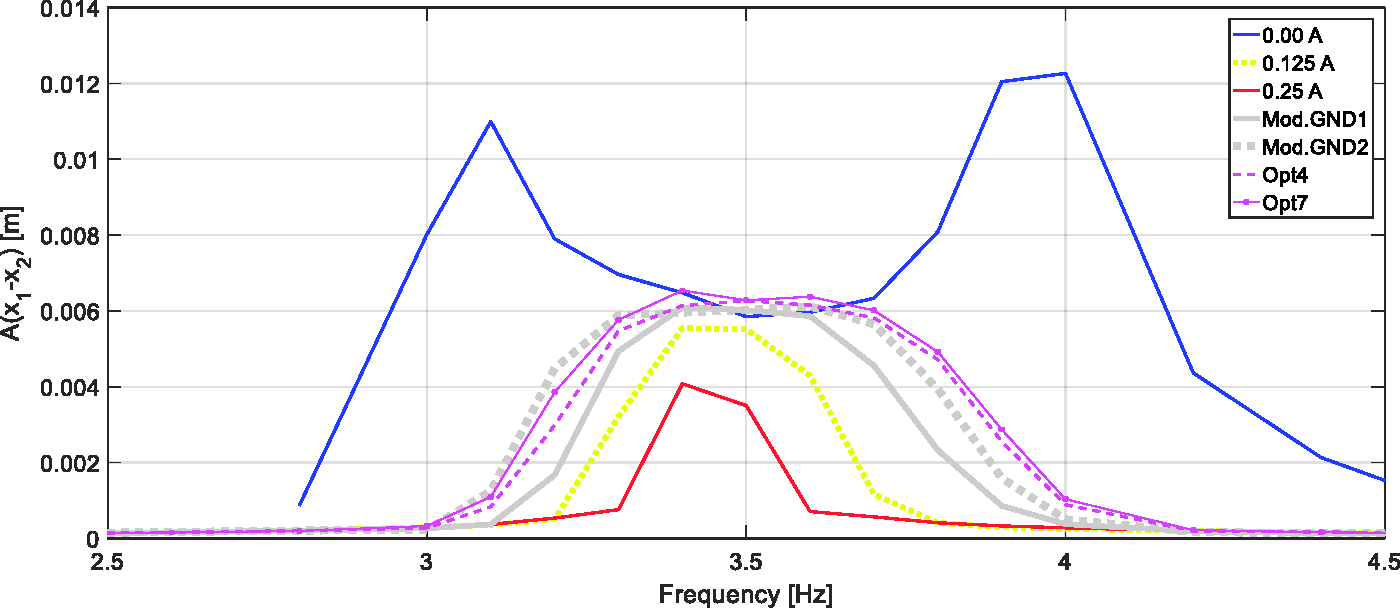
The MR damper stroke amplitude
The MR damper stroke amplitude
The MR damper stroke amplitude
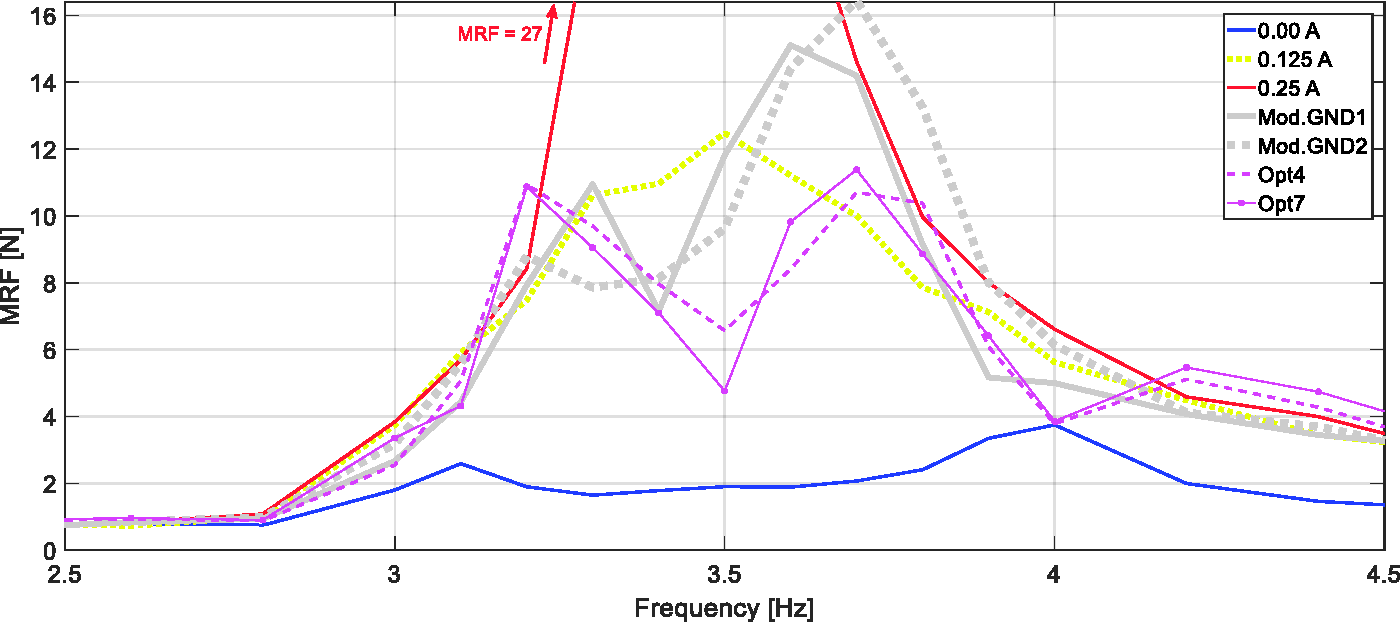
The MR damper force amplitude MRF frequency characteristics: passive system vs. Mod.GND1&2 vs. Opt4&7.

The MR damper force amplitude MRF frequency characteristics: Opt7 for different
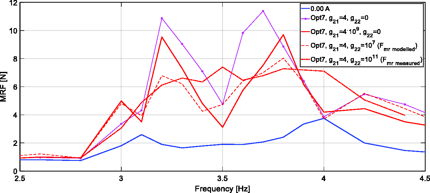
The MR damper force amplitude MRF frequency characteristics: Opt7 for different
Figures 12 to 14 present the comparison of the primary structure deflection
As may be observed (Figure 3), an MR damper force correction algorithm (Mod.GND2) improves the attenuation properties by more precise
Observing Figures 4, 7, 10, and 12, one may note that the MR damper stroke amplitude
Similarly, observing Figures 5, 8, 11, 12(a) and (d), 13(a) and (b), and 14(a) and (b), it is evident that by increasing
Remark
For the control cases I and II, no truncate effect at
Using the
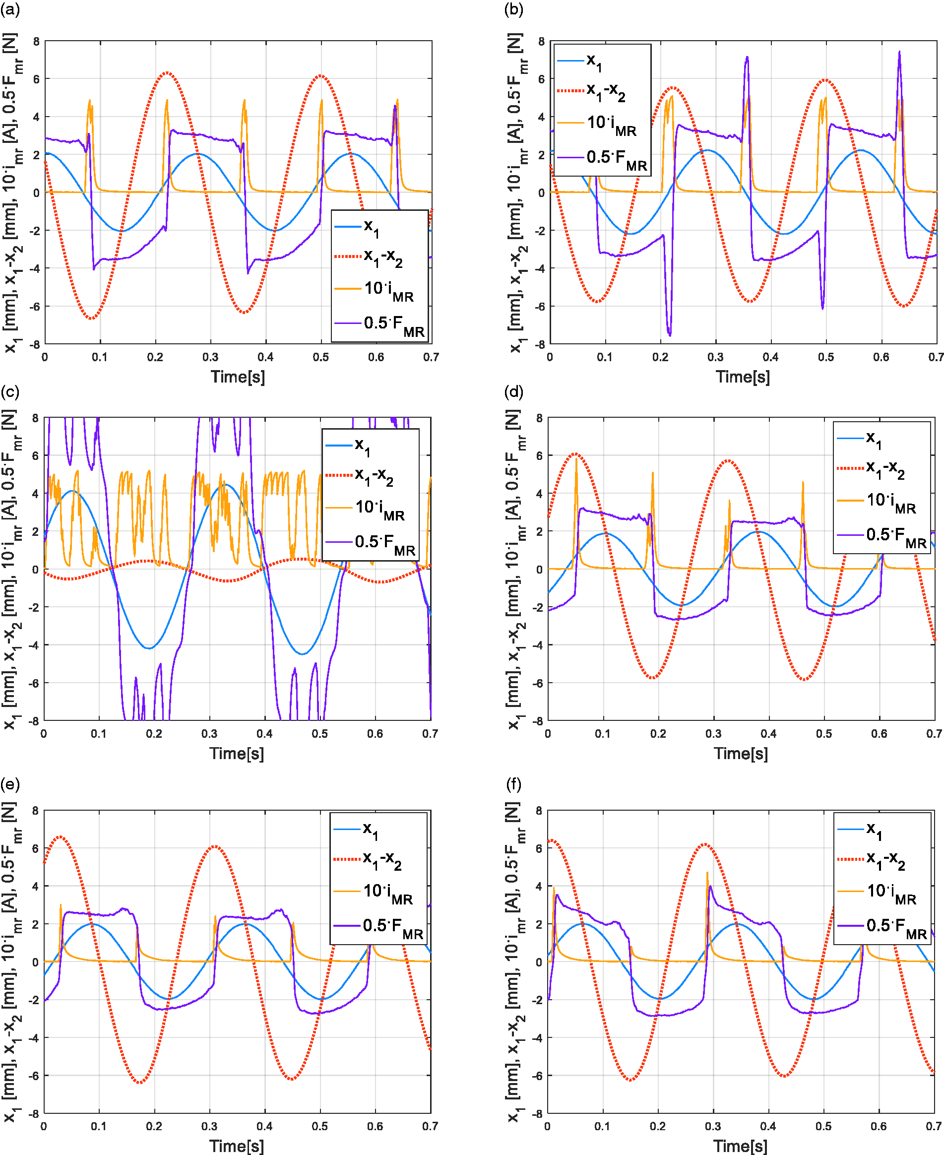
Time responses at 3.6 Hz: (a) Opt7, (b) Opt7,
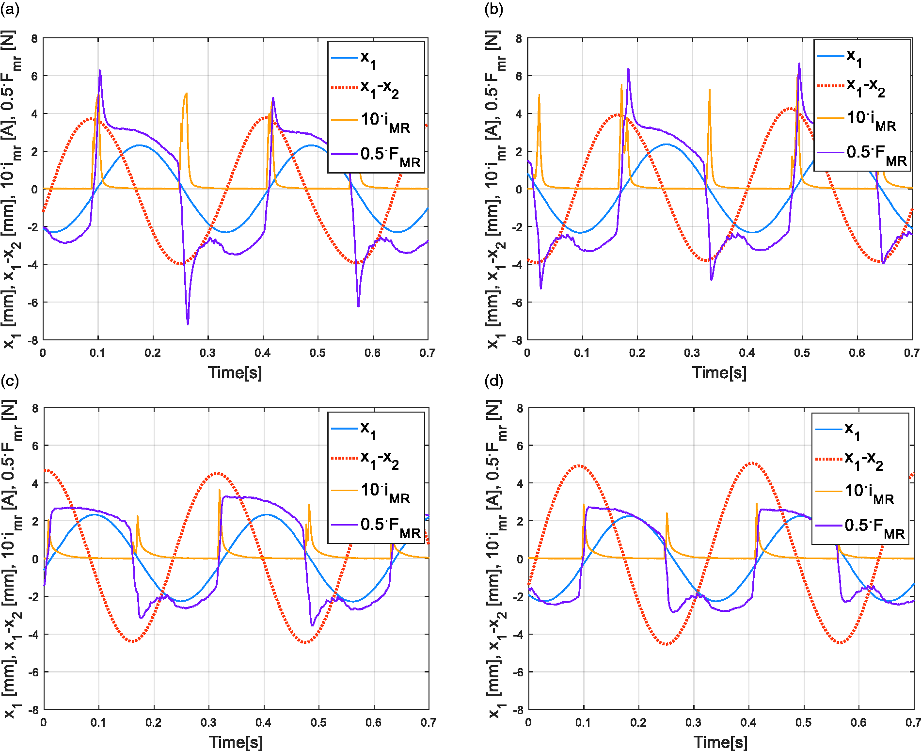
Time responses at 3.2 Hz: (a) Opt7, (b) Opt7,
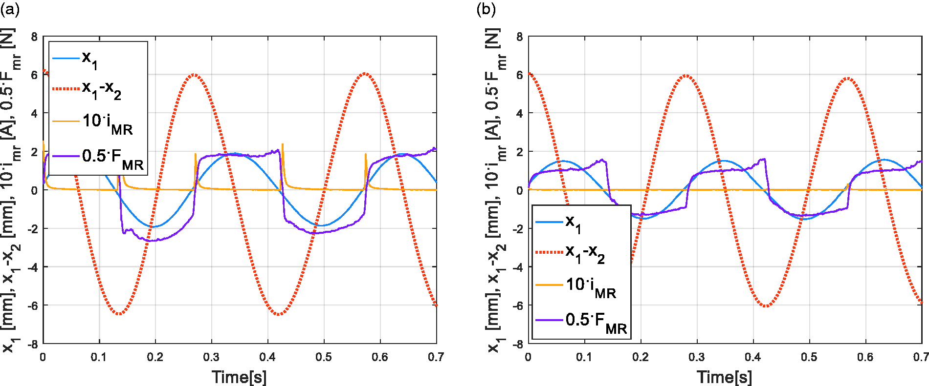
Time responses at 3.5 Hz: (a) Opt7, (b) Opt7,
Recapitulating, by increasing the
Conclusions
The aim of the current research was a real-time implementation and experimental test of the nonlinear optimal-based vibration control technique for a system/structure (namely a wind turbine tower-nacelle model) equipped with an MR TVA. Using a simple hardware, the previously developed technique30 was successfully implemented and verified, including additional optimisation fields covered by a nonlinear optimal control quality index, in comparison with simple yet reliable (optimal-based) modified ground-hook law, and passive solutions with constant MR damper current. The obtained maximum DAF values of ca. 2.0 are more than adequate for the assumed 7.69% TVA mass ratio, proving the effectiveness and validity of the control approach. 30 Neither MR damper force tracking nor oscillation frequency determination is necessary online; thus, control quality is not compromised by MR damper force constraints, while real-time control during transient, polyperiodic or random vibration phases is unimpeded; also neither offline calculation nor disturbances assumption is necessary, all essential for continual real-time control.
The experimental tests proved that the Opt7 method delivers the most valuable vibration control results, especially in comparison with a reference modified two-level displacement ground-hook law that previously demonstrated one of the best vibration reduction properties.5,6,22,30 However, the Mod.GND algorithm is devoted for the case when only the primary system displacement amplitude has to be minimised, while the proposed solution copes well with different constraints (optimisation fields) as, e.g. working space, MR damper stroke, current or force, that may be encountered during the operation of real-world systems.
Footnotes
Declaration of conflicting interests
The author(s) declared no potential conflicts of interest with respect to the research, authorship, and/or publication of this article.
Funding
The author(s) disclosed receipt of the following financial support for the research, authorship, and/or publication of this article: This work was supported by AGH University of Science and Technology (research program no. 11.11.130.766); and the Polish National Science Centre (NCN) (decision no. DEC-2013/11/D/ST8/03387).