
Abstract
This work covers selected control issues, including refined force tracking algorithm formulation, concerning the wind turbine tower-nacelle laboratory model equipped with a magnetorheological damper based tuned vibration absorber. The objective of the current research is a development and experimental implementation of the control algorithm that couples basic adaptive stiffness solution with stock magnetorheological damper force tracking concept to obtain a quality tower vibration reduction system. The experiments were conducted assuming monoharmonic, horizontal excitation applied to the assembly modelling the nacelle. The frequency range comprised the neighbourhood of the first bending mode of the tower-nacelle system. The results proved the effectiveness of the adopted algorithm referring to other high-performance solutions.
Introduction
The wind energy sector is rapidly growing nowadays. Wind turbines are ecological solutions, yet their implementation cost is significant. Structural vibrations and their consequences imply a relatively high investment into the construction process, which is one of the greatest contributors to the amount that wind farm implementation costs. The aerodynamic load (and the hydrodynamic/ice load for offshore structures) that varies in time, including wind shear, Karman vortices, blade-passing effect, differences in inflow conditions for each of the blades, as well as rotating turbine elements’ unbalance and generator operation are the major contributors to the structural vibrations of towers and blades. 1 The cyclic stress, that the tower is subjected to, may decrease reliable operation time due to the structure fatigue wear 2 or even a failure accident. These vibrations are generally lightly damped, especially considering the low aeroelastic damping for the first tower lateral mode.3–6 The lateral modes are excited due to Karman vortices, generator operation, sea wave variable load and rotating machinery unbalance rather than due to direct wind-load variations and the blade-passing effect, as for longitudinal modes. In the current project, only tower vibration is being analysed.
The solutions utilised to reduce wind turbine towers’ vibrations include collective blade pitch control, generator electromagnetic torque control,7–9 and tuned vibration absorbers (TVAs).10–13 In the standard (passive) approach, a TVA consists of an additional moving mass, spring and viscous damper whose parameters are tuned to the selected (most often the first) mode of vibration.10,14 Passive TVAs work well at the load conditions characterised with a single frequency to which they are tuned, but cannot adapt to a wide excitation spectrum; 15 hence, more advanced TVAs are required to change/tune the TVA operating frequency. Among them, magnetorheological (MR) TVAs are placed, 15 as using an MR damper instead of a viscous one guarantees wide range of resistance force, millisecond response time, high operational robustness including lower sensitivity to temperature change and minor energy requirements as compared with active systems.16–23 Simulations and experiments show that implementation of an MR damper in the TVA system may lead to further vibration reduction in relation to passive TVA.24–27
Within the scope of the current project, a specially developed and built tower-nacelle laboratory model (Figure 1) was made, in which all turbine components (a nacelle, blades, a hub, a shaft, a generator and possibly a gearbox) are represented by nacelle concentrated mass. The laboratory test rig of the wind turbine tower-nacelle system makes it possible to model tower vibrations under various excitation sources, as the horizontal concentrated force generated by the dedicated shaker may model the load applied to the nacelle or to the tower itself at the arbitrary height. Both locations enable to force tower bending modes of vibration. The rig may also be laid down on the horizontally excited platform to model the vibrations of buoy-floating wind turbine structures, or vibrations due to seismic excitation.
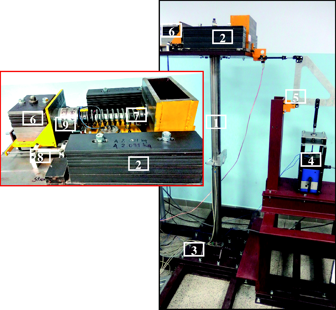
The laboratory test rig.
The problem of wind turbine tower vibration control with an MR TVA, utilising an adaptive stiffness concept with a newly developed force tracking algorithm, is presented here. Both the adaptive stiffness and the MR damper force tracking solutions were investigated previously separately; however, only limited (numerical or hardware in the loop only, continuous – with no discontinuities or two-level force/current pattern regarded) implementation scenarios were presented,28–32 or the quality of the force follow-up left the field for further improvements.24–26 The MR damper real-time force tracking problem along with the adaptive stiffness and damping/friction was investigated extensively with fair results in previous studies.33–36 Weber 33 uses a series of Bouc–Wen models computed in parallel to estimate the required control current with no need of force sensor, however, the presented measured tracking of clipped viscous damping with negative stiffness exhibits slow force rise after piston velocity sign change. The interesting logics is adopted in a study 34 for a system-tailored MR damper, dealing separately with the regions of rapid MR damper force increase, decrease, and the transition between these two relations, together with the negative current spikes just before the desired force sign changes. However, measured real-time tracking of force patterns exhibiting negative stiffness is again characterised with insufficiently sharp force rise, while tracking of force patterns exhibiting positive stiffness is characterised with significant force error (overshoot) due to the remanent magnetization. These two problems, occurring either when the actual MR damper force should be quickly increased to a large value or when the force should be rapidly decreased to zero, both at the displacement extreme (and force sign change), are not removed by this approach utilising MR damper inverse model feed forward and force sensor feedback, even using negative current applied on each half cycle. 35 Weber 36 also uses MR damper inverse model combined with force sensor. Again, measured real-time tracking of force patterns is characterised with insufficiently rapid force rise or significant overshoot, both after force sign change.
The current work covers real-time realisation of the improved (over the previous solutions24–26,29,31,32,37) stock MR damper continuous pattern tracking algorithm coping well with the discontinuities (rapid value changes) of the force and the magnetic remanence, combining MR damper forward model with force sign change prediction (feed forward), force sensor feedback and dedicated logics, together with a basic adaptive stiffness implementation, resulting in a quality vibration reduction system. As a reference, passive solutions with several MR damper constant input current values, the adaptive stiffness concept with previously tested MR damper hyperbolic tangent inverse model and PI-based force tracking algorithms,24–26,29,31,32,37 along with a modified ground hook control25,26 results are presented. Only the first bending mode of vibration frequency neighbourhood is analysed here.
The paper is organised as follows. In the forthcoming section, the wind turbine tower-nacelle laboratory model is introduced. Then, a vibration control algorithm is presented and followed by the experimental analysis results. The paper ends with several conclusions.
The wind turbine tower-nacelle laboratory model
The model to be analysed (Figure 1) consists of a titanium (Ti Gr.5) rod 1 arranged vertically, representing the wind-turbine tower, and a stiff body (system of steel plates) 2 fixed rigidly to the top of the rod, representing both nacelle and turbine assemblies. The bottom end of the rod is rigidly mounted to the ground via an adequately stiff steel foundation frame 3. As the first tower bending mode has dominant modal mass participation (ca. fivefold greater than the next mode), a vibration reduction system (an MR TVA) is located at the top of the rod (at the nacelle). The MR TVA is an additional stiff body 6 (an absorber), moving horizontally along linear bearing guides, connected with the system representing the nacelle via a spring and Lord RD 1097–1 MR damper 38 in parallel 7. The absorber mass m2 and the spring stiffness k2 parameters of the TVA were tuned to the first bending mode of the tower-nacelle system vibrations on the basis of standard principles of the TVA tuning. 10 The RD 1097-1 damper (whose force depends on the current fed to its coil) is an actuator of such a vibration reduction system. The MR TVA operates along the same direction as the vibration excitation applied (assuming small bending angles). Force excitation system comprises The Modal Shop lightweight electrodynamic force exciter of 2060E series 4 39 with the drive train assembly 5 of the changeable leverage.40–44
The horizontal displacement and velocity of the system modelling the nacelle are designated by x1 and v1 (respectively) while the horizontal displacement and velocity of the absorber (the TVA mass) are x2 and v2. Thus, x1–x2 designates the MR damper relative displacement (that is measured by LVDT transducer 8), while v1–v2 designates the MR damper relative velocity. The MR damper force PMR is measured by the tensometric transducer embedded in a casing 9.
Control algorithm
The underlying idea of the implemented control system is presented in Figure 2. Three measurement input signals are regarded: spring / MR damper relative displacement x1–x2meas, MR damper current iMRmeas and MR damper force PMRmeas. The MR Damper Required Force subsystem corresponds to the real-time calculation of the demanded MR damper force PMRreq – for the purpose of the current analysis, the algorithm of the undamped dynamic vibration absorber
10
that tracks excitation frequency25,26,28 is emulated using the MR damper. The MR damper should generate positive or negative stiffness force in such a way that the TVA stiffness


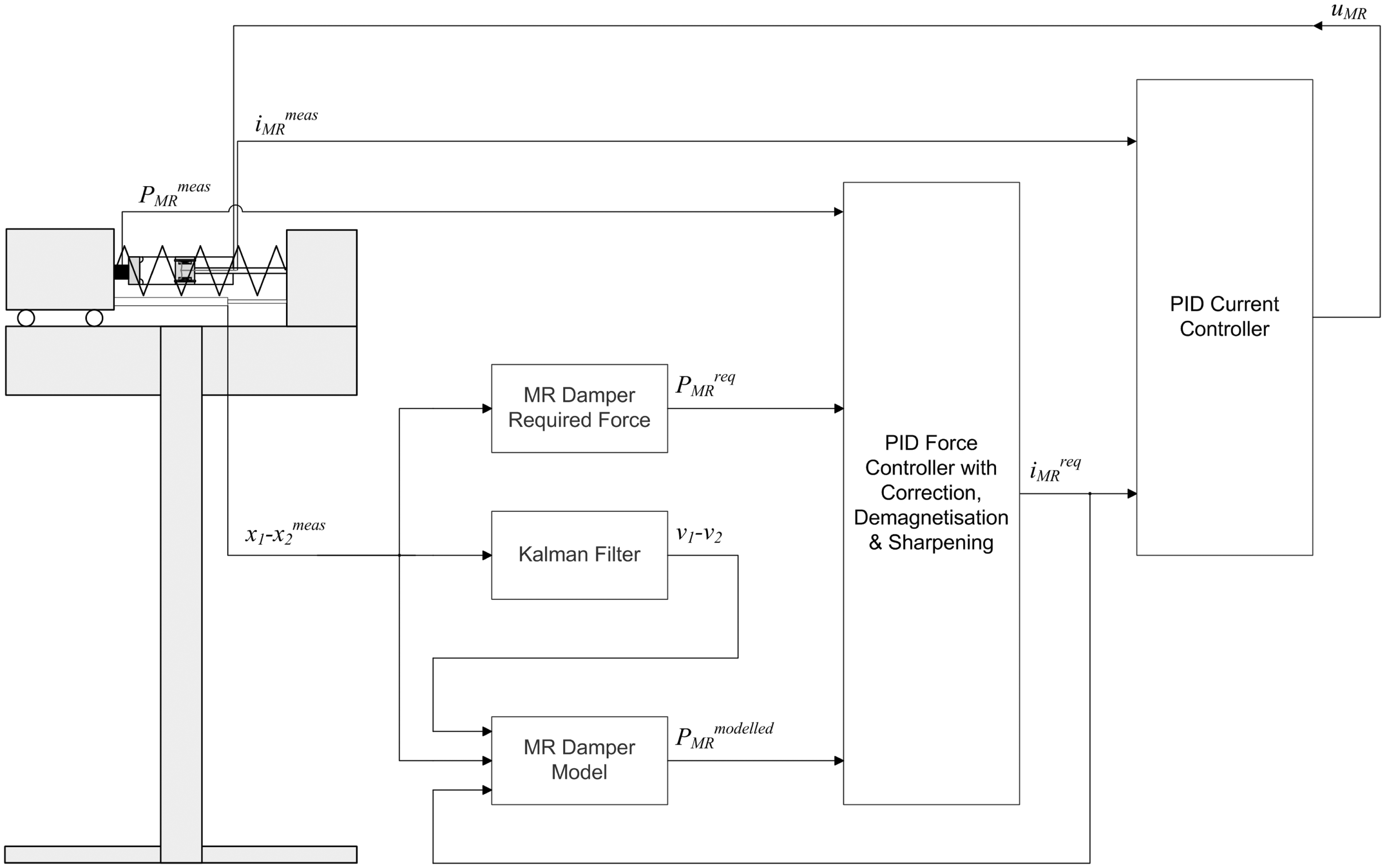
The schematic diagram of the control system.
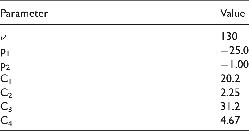
When active forces are required, zero force is assumed. Thus arises a problem of a precise MR damper force tracking in the case of pattern being discontinuous due to such clipping. A quick, timeous (with possible prediction) and sharp force follow-up is needed, whereas the actuator dynamics exhibits the inertia due to the coil electrical resistance and inductance, magnetic remanence, as well as the time lag / hysteresis resulting from the MR effect (particle chains formation) delay / MR fluid preyield operation regime. These effects cannot be eliminated by a simple PI / PID feedback controller with the sign adjustments24–26,31,32,37 as it can shape the force–velocity relationship only into a linear or a higher-order polynomial function, with the inherent time lag, even utilising the adequate current controller. Thus, a dedicated MR damper force follow-up PID based control algorithm, that was specially developed and refined during the current study based on earlier studies,25,26,31 is represented by the PID Force Controller with Correction, Demagnetisation & Sharpening subsystem (see Figure 2). Apart from the demanded MR damper force PMRreq input, the measured actual MR damper force PMRmeas and the modelled MR damper force PMRmodelled signals are fed to the input of this subsystem. PMRmodelled is the real-time calculated force with the use of the MR damper forward hyperbolic tangent model (the MR Damper Model subsystem) in the form of

The adopted parameters of the MR damper model.
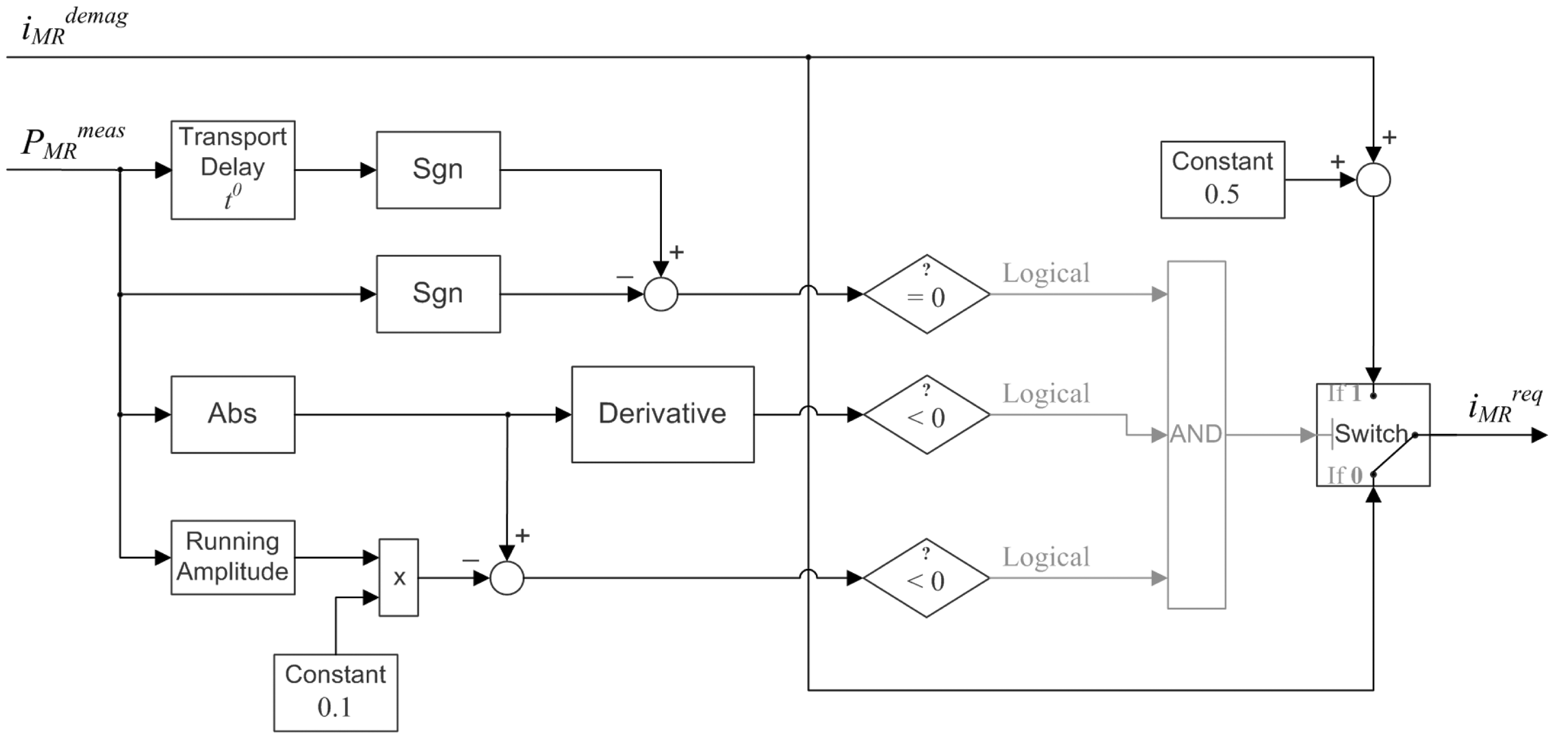
The PID Force Controller with Correction, Demagnetisation & Sharpening subsystem diagram is depicted in Figure 3. Its three main elements are: the PID Controller with Correction, the Demagnetisation, and the Response Sharpening subsystems.
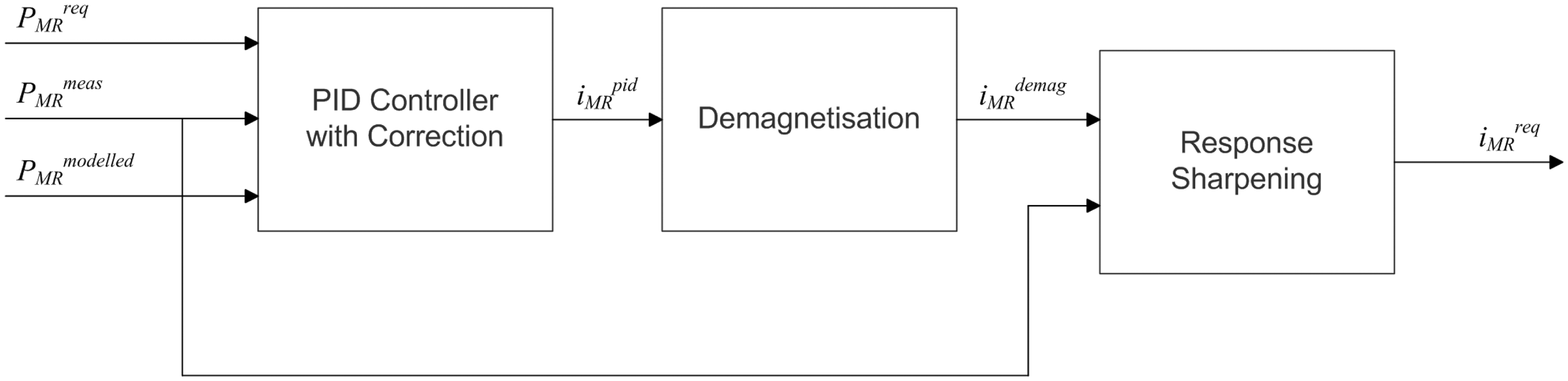
The diagram of the PID Force Controller with Correction, Demagnetisation & Sharpening subsystem.
The primary version (V.1) of the PID Controller with Correction subsystem is depicted in Figure 4. It consists of the Abs blocks, the Gain block Alpha1 as the scaling factor (Alpha1 > 1 is necessary as |PMRreq|=|PMRmeas| case should not result in zero control), the PID Controller with Alpha2 Constrained Integration block (Alpha2 < 1 multiplier constraints the integral action when: Alpha1|PMRreq|≤|PMRmeas|), the multiplying blocks, sign relations of PMRreq&PMRmeas, PMRreq&PMRmodelled and PMRmeas&PMRmodelled determination conditional (rhombus) blocks with logical (marked in grey) outputs and the Switch blocks with grey logical inputs and black switched signals inputs. Standard automatic control PID tuning techniques were used for the selection of proportional P, integral I and derivative D path gains. Additionally, the Saturation block is used with constants: idemag=1.5·10−2 A (the MR damper magnetic path & MR fluid particles demagnetisation current value) and imax=1.5 A, while the Gain ‘–1' is for negation and the Max block with ‘–0.2·imax' (–0.3 A) constant input are used to sharpen the system response when PMRmeas changes sign (while PMRreq sign is maintained), what is predicted by PMRmodelled signal, to set the instantaneous current adequately early to –0.3 A and, moreover, obtain minimum MR damper residual force modulus (that is greater due to the remanent magnetisation) after PMRmeas sign change (see time range of (0.315, 0.350) s in Figures 18, 19 and 21(b) vs. Figures 16 and 17). Such constructed MR damper force tracking idea is insensitive to MR damper dynamics changes due to, for example, temperature or stroke amplitude variation during its operation as PMRmodelled sign is considered here instead of PMRmodelled value.
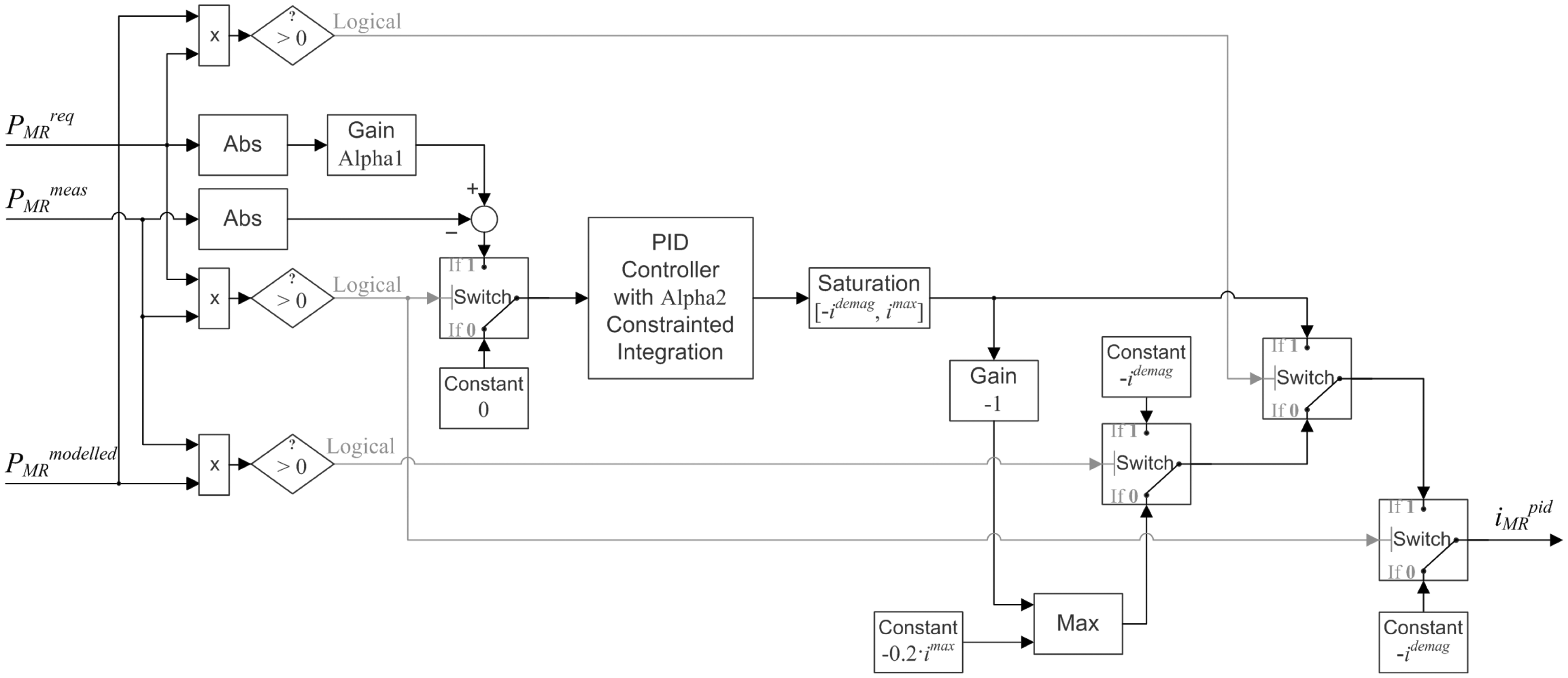
The diagram of the PID Controller with Correction subsystem, V.1.
The second version (V.2) of the PID Controller with Correction concept is depicted in Figure 5. It differs from V.1 by an idea of the integrator resetting when PMRmeas and PMRmodelled have the opposite signs, while the integrator initial condition (after the reset) is Alpha3 (Alpha3 < 1) times the most recent nonzero integrator state. This solution is implemented to cope with the integrator wind-up problem that may be observed for the V.1 concept (see Figure 18 vs. Figure 19 starting e.g. at 0.05 s) and comes along with possibly enlarged I path gain and higher integration constraint Alpha2 (Alpha2 < 1) in relation to V.1 concept.
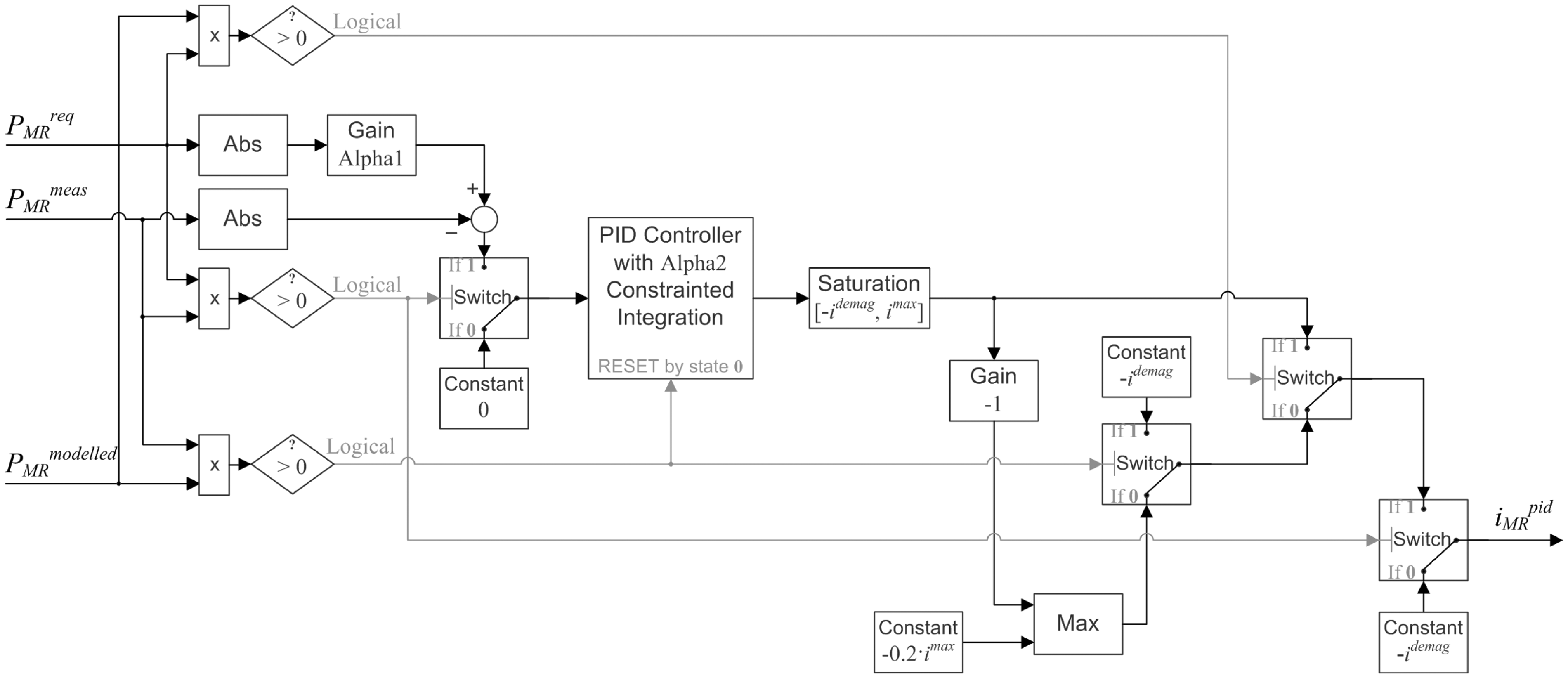
The diagram of the PID Controller with Correction subsystem, V.2.
The Demagnetisation subsystem (see Figure 3) is depicted in Figure 6. It produces the exponentially decaying current pattern (due to the presence of derivative element with first order inertia and T = 0.067·tperiod, where: tperiod=
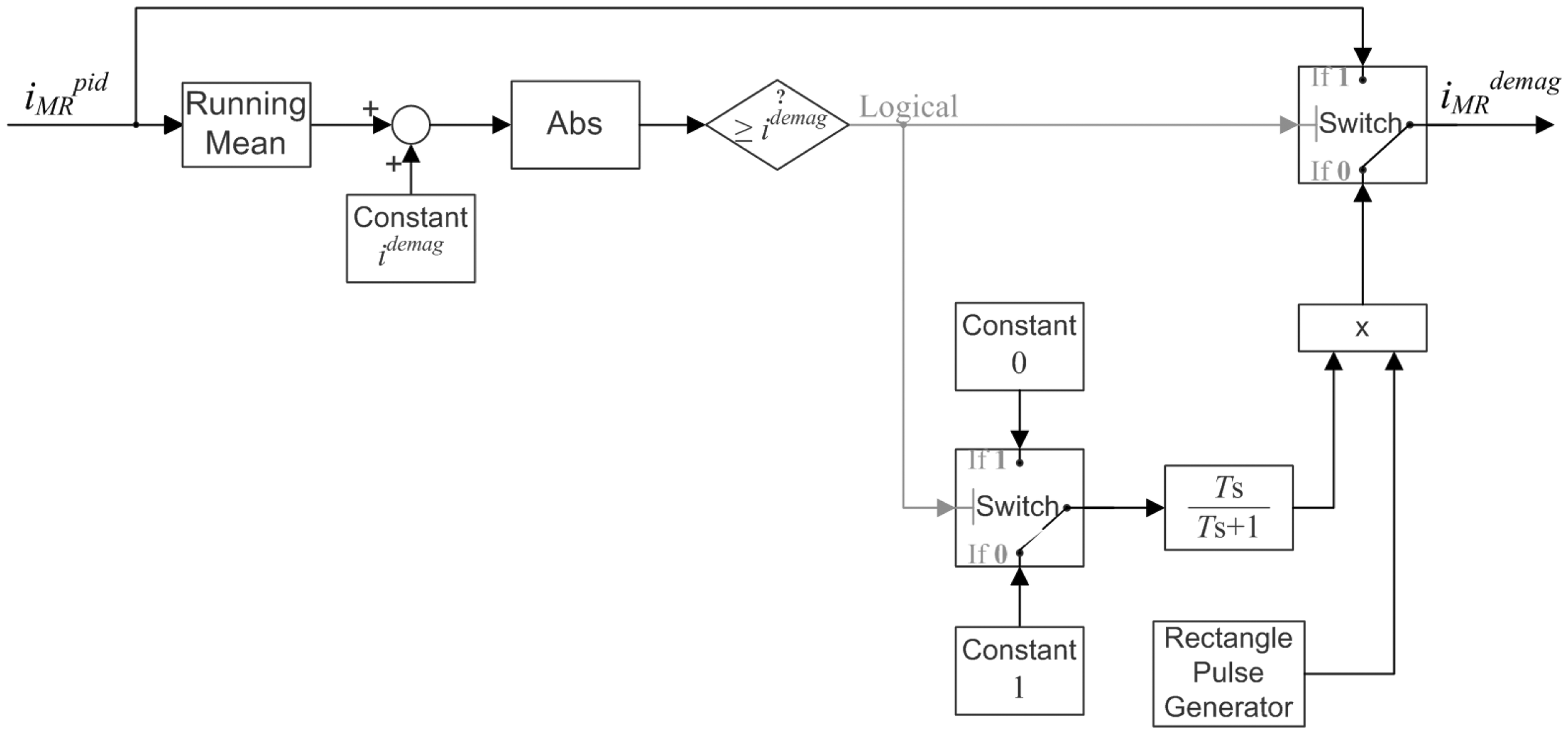
The diagram of the Demagnetisation subsystem.
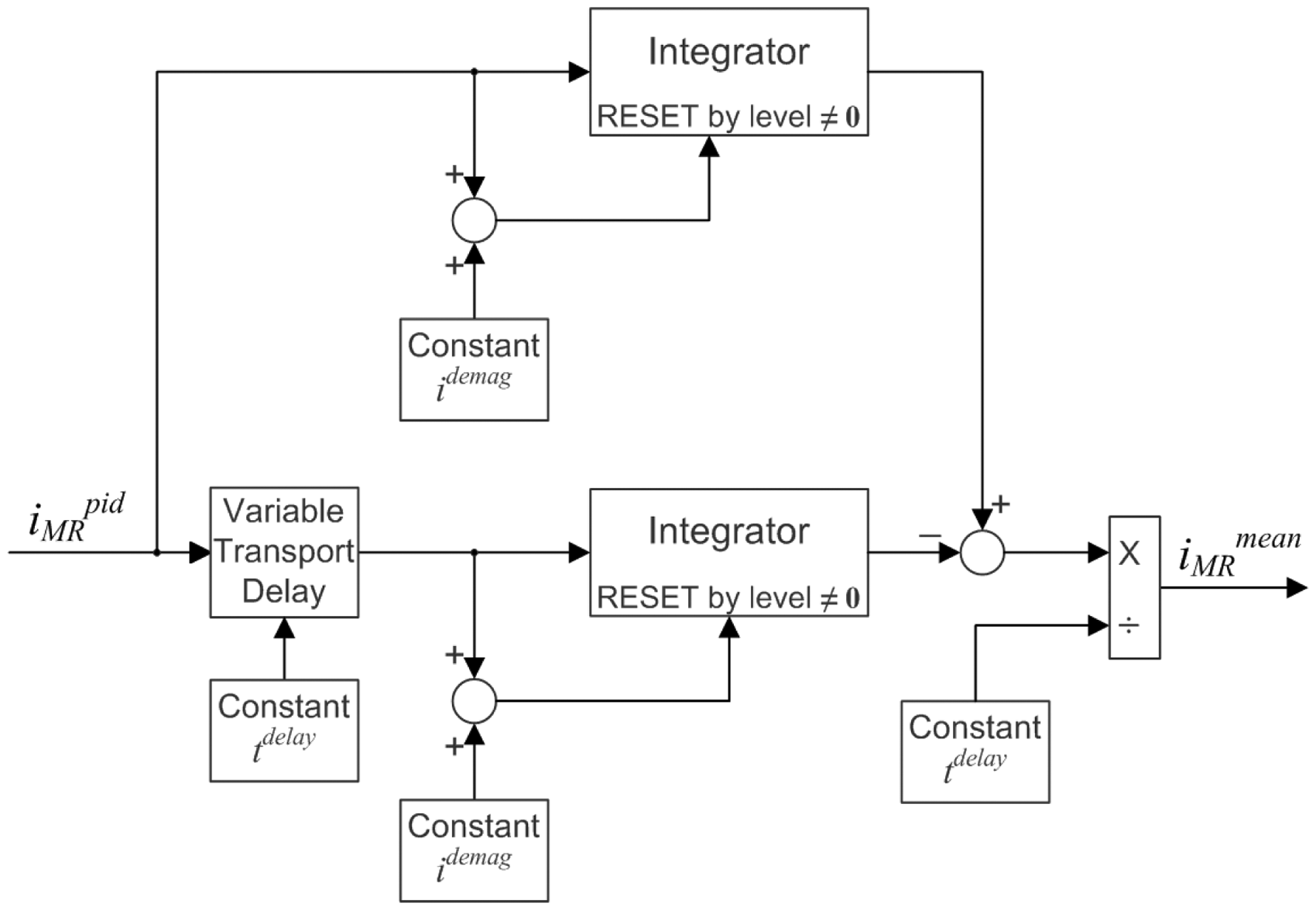
The diagram of the Running Mean subsystem.
The Response sharpening subsystem (see Figure 3) is presented in Figure 8. Its aim is to sharpen the MR damper response at the moment of PMRmeas signal sign change while PMRreq sign has changed earlier, however the MR damper (as a dissipative device) was unable to produce the active force (see Figures 13 and 14). To fulfil this task, the control current is enlarged by the value of 0.5 A when PMRmeas modulus is decreasing and is lower than 10% of PMRmeas running amplitude, and PMRmeas sign is consistent within last two sampling periods t0 (see Figures 13, 14 and 21(a), t0=1·10−3 s was assumed). Thanks to such logics, the required value of the control current iMRreq precedes the sign change of PMRmeas; thus the control current that actually flows through the MR damper coil iMRmeas is set at the moment of the PMRmeas sign change with no delay. The Running Amplitude subsystem (Figure 9) calculates the difference of the outputs of the two integrator blocks with delay of five oscillation periods between them. The input to both integrators is the quantity (PMRmeas) squared (Sqr block). The resultant difference is multiplied by two and divided by a time of five periods to obtain the amplitude squared; thus, finally the Sqrt (square root) block is needed only to obtain amplitude A(•) of the input signal (assuming that the vibration pattern is characterised by single dominant frequency, what is the case in the most real-world wind turbine structures’ operation scenarios).
The diagram of the Response sharpening subsystem.
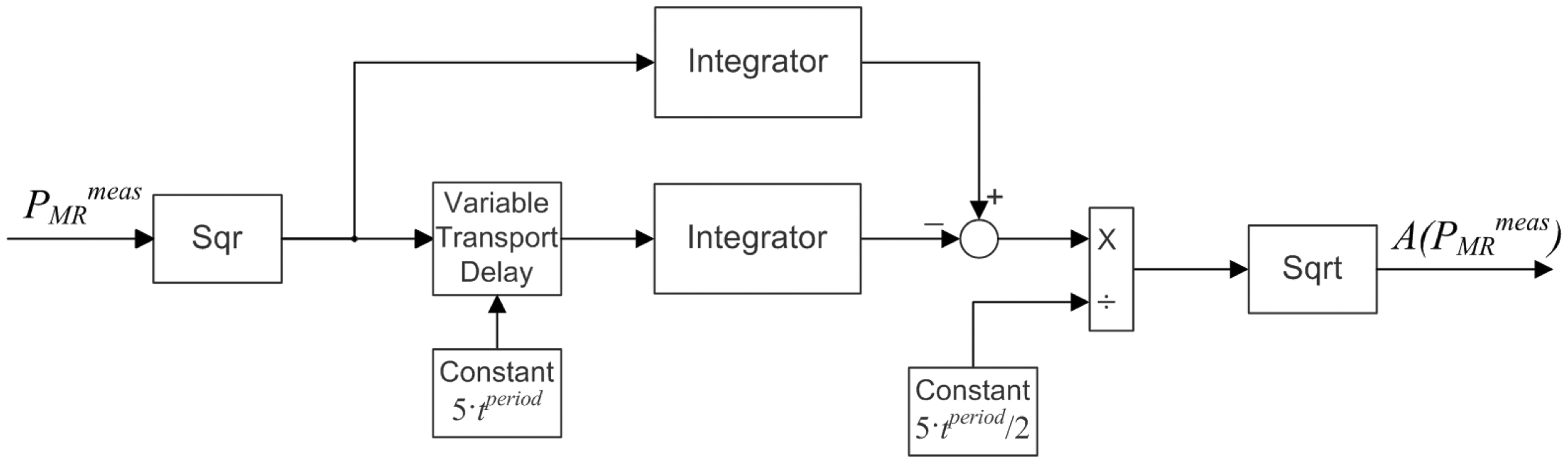
The diagram of the Running Amplitude subsystem.
The parameters imax, idemag, tdelay, Alpha1, Alpha2 and Alpha3 values were selected on the basis of numerical simulations supported by MR damper dynamics experimental testing.
The system in Figure 2 also includes standard analogue PID Current Controller subsystem aimed to control MR damper with the use of an electronic board that enforces the MR damper current via a control voltage uMR, based on iMRmeas and iMRreq signals (see Figure 22 (a) and (b)).
Experimental analysis
For the purpose of the current experimental analysis that is oriented to the development of the refined MR damper force tracking algorithm, the value of γ = 1 was assumed, while the selection of γ was not a scope of the present research. The theoretical study of γ determination for the idealised semiactive device of negligible response time, zero residual force and zero inherent system damping is presented in literature. 28
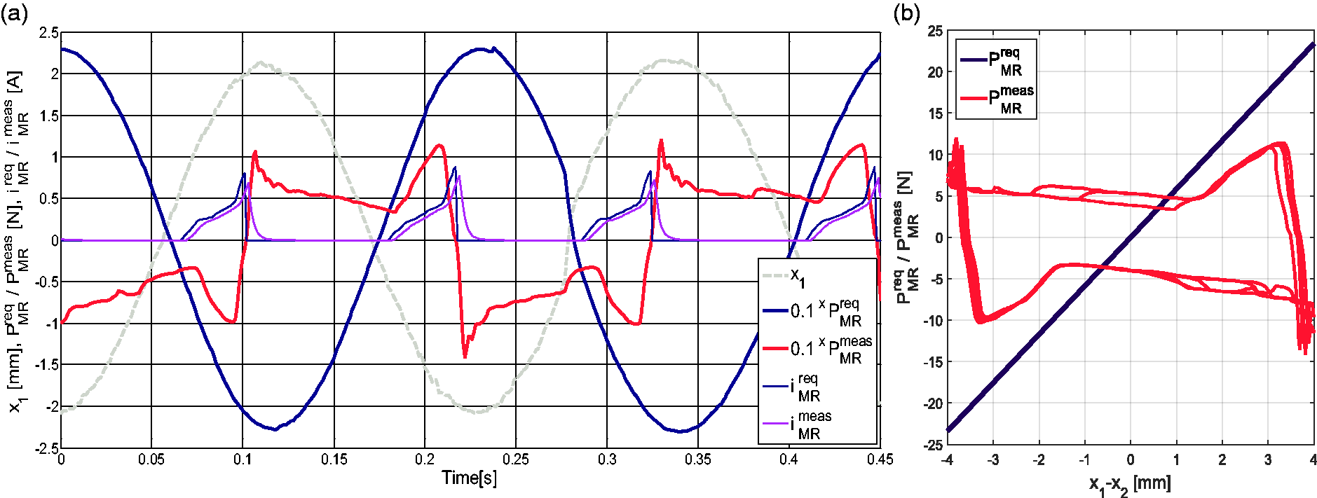
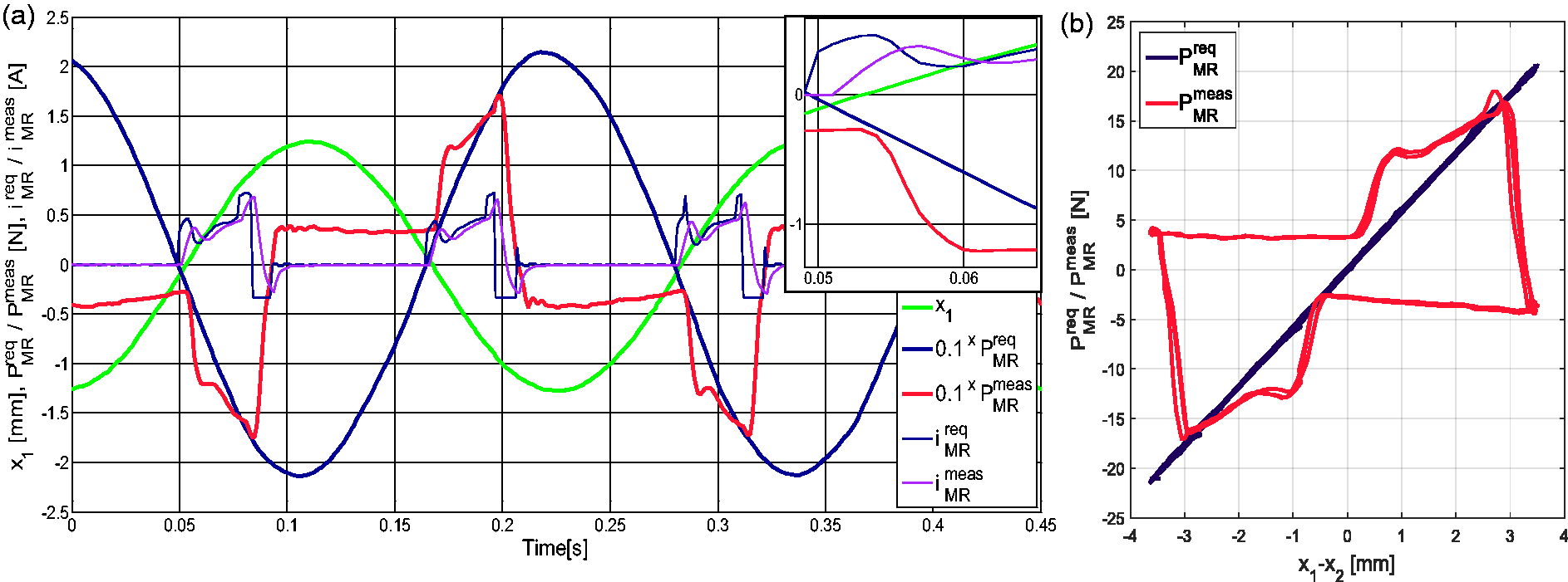
The experiments were conducted assuming P0 = 61 N amplitude of the monoharmonic, horizontal excitation applied to the nacelle. The frequency range comprised the neighbourhood of the tower-nacelle system’s first bending frequency, i.e. (2.50, 5.00) Hz. Several system configurations were regarded: passive system with the constant control current of 0.0, 0.1, 0.2, 0.3, 0.4 and 0.5 A, and the adaptive solutions (according to equation (1)) with the newly developed V.1 and V.2 force tracking algorithms (ADPT V.1 and ADPT V.2, respectively), or with the simple, previously tested MR damper hyperbolic tangent inverse model (ADPT INV, derived directly from equation (3)) and PI based force tracking algorithm (ADPT PI).25,26 As a reference solution, the modified ground hook algorithm (Mod.GND) that was previously proved to be the best approach24–26 was selected. All the obtained output frequency response functions of the tower tip horizontal displacement x1 amplitude are presented in Figure 10. Figures 11 to 20 contain time responses of the tower tip displacement x1, the MR damper force PMRreq/PMRmeas and the MR damper current iMRreq/iMRmeas (adequately scaled to fit the same coordinate axes, indicated by (a)) alongside the MR damper force-displacement loops (indicated by (b)), obtained for the respective systems (ADPT INV, ADPT PI, ADPT V.1, ADPT V.2 and Mod.GND) at the frequency of 2.95 Hz (Figures 11 to 15) and 4.35 Hz (Figures 16 to 20). Frequency neighbourhoods of 2.95 Hz and 4.35 Hz are the most crucial concerning preferable control solutions (see Figure 10, open loop systems are not of interest here). Figure 21(a) and (b) contains section of time responses of the MR damper force PMRreq/PMRmeas, and the MR damper current iMRreq/iMRmeas (adequately scaled), obtained for the system ADPT V.2 at 2.95 Hz and 4.35 Hz (selective zoom of Figure 14 and 19, respectively). Time patterns illustrating the PID Current Controller operation at positive / negative step change of iMRreq are given in Figure 22(a) and (b) (respectively).
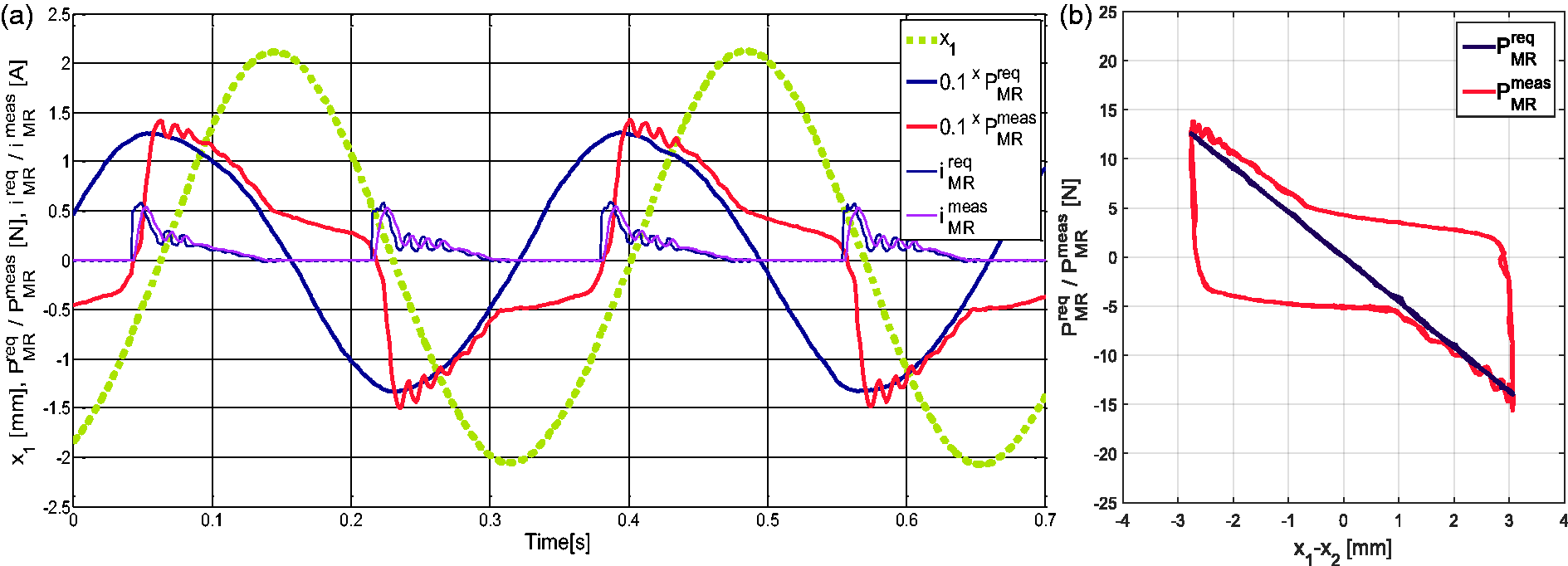
Tower tip displacement amplitude output frequency response functions. ADPT INV system at 2.95 Hz: (a) time responses and (b) MR damper force-displacement loops. ADPT PI system at 2.95 Hz: (a) time responses and (b) MR damper force-displacement loops.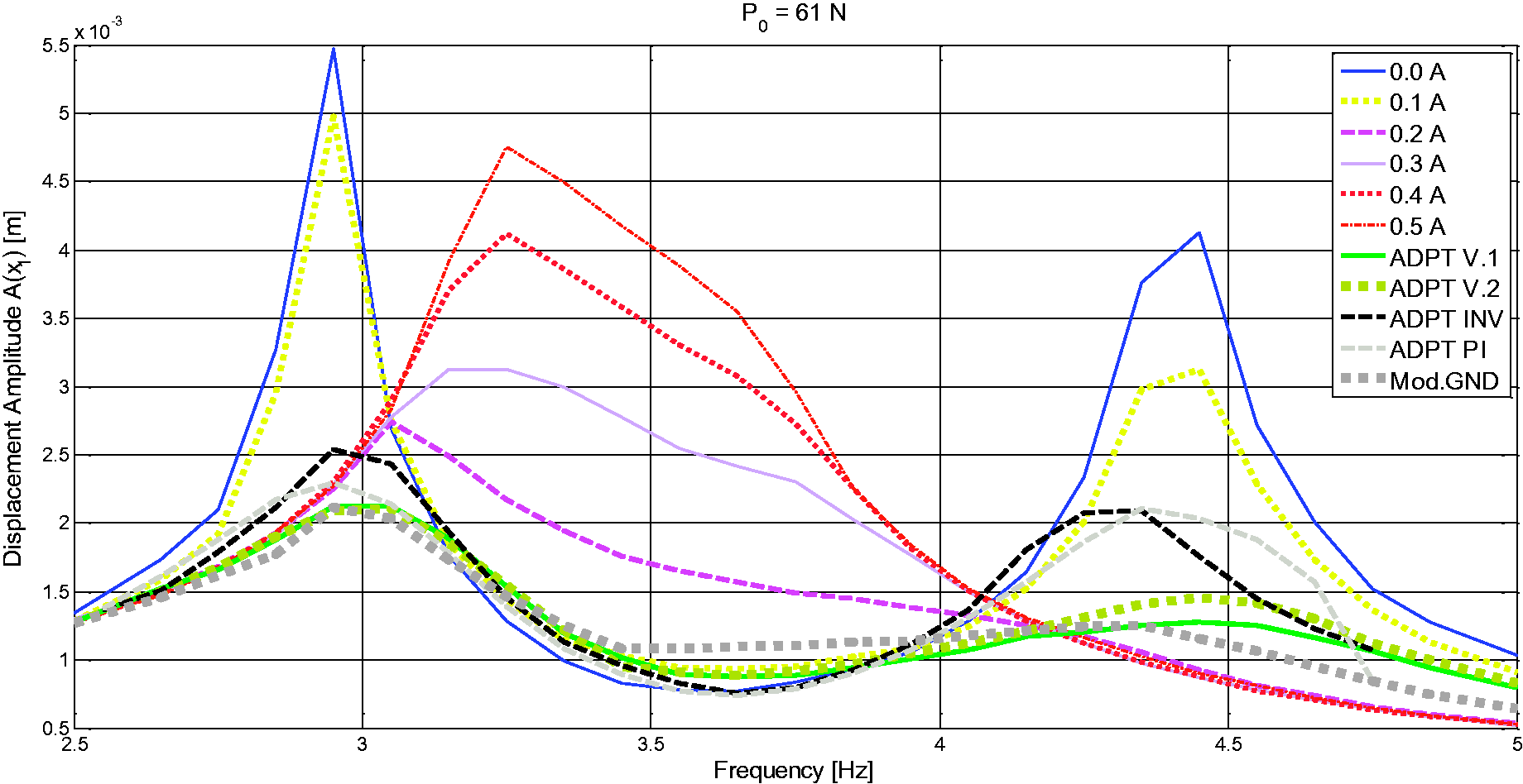
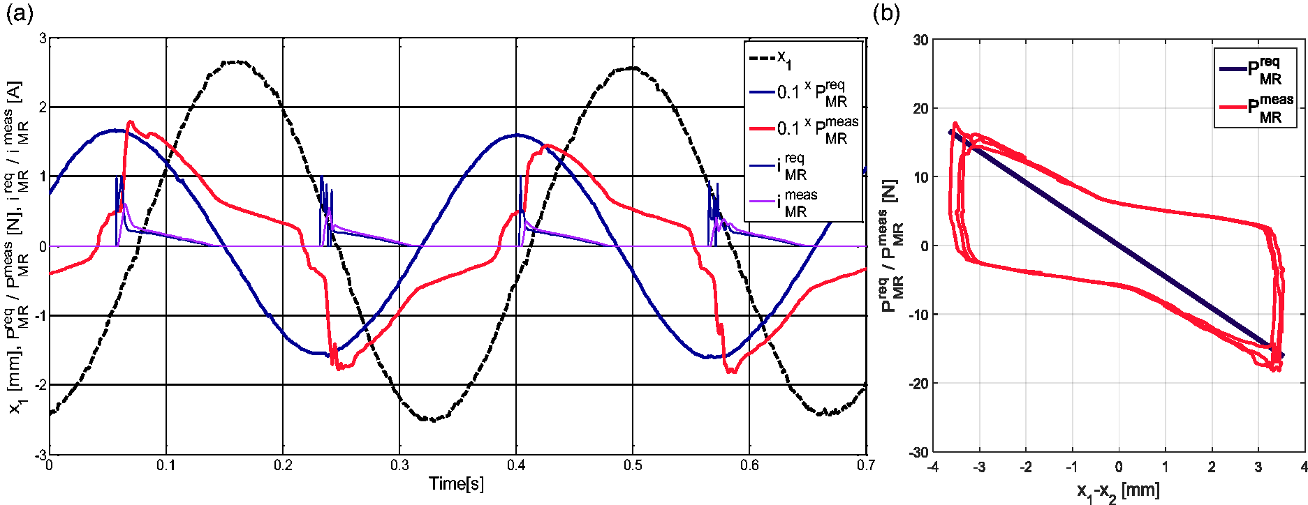
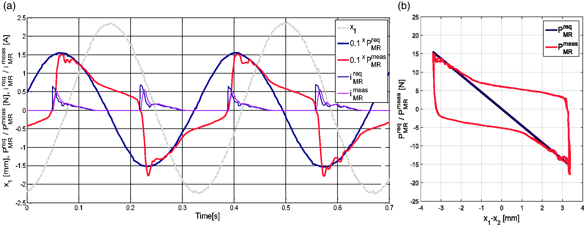
Table 2 presents values of the quality index Q (best values in bold) being a root-mean-square of the PMRreq–PMRmeas difference
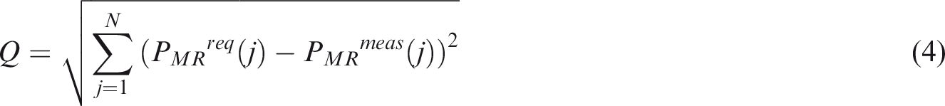
Values of the quality index Q calculated using equation (4).
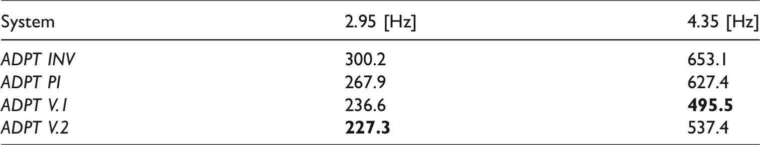
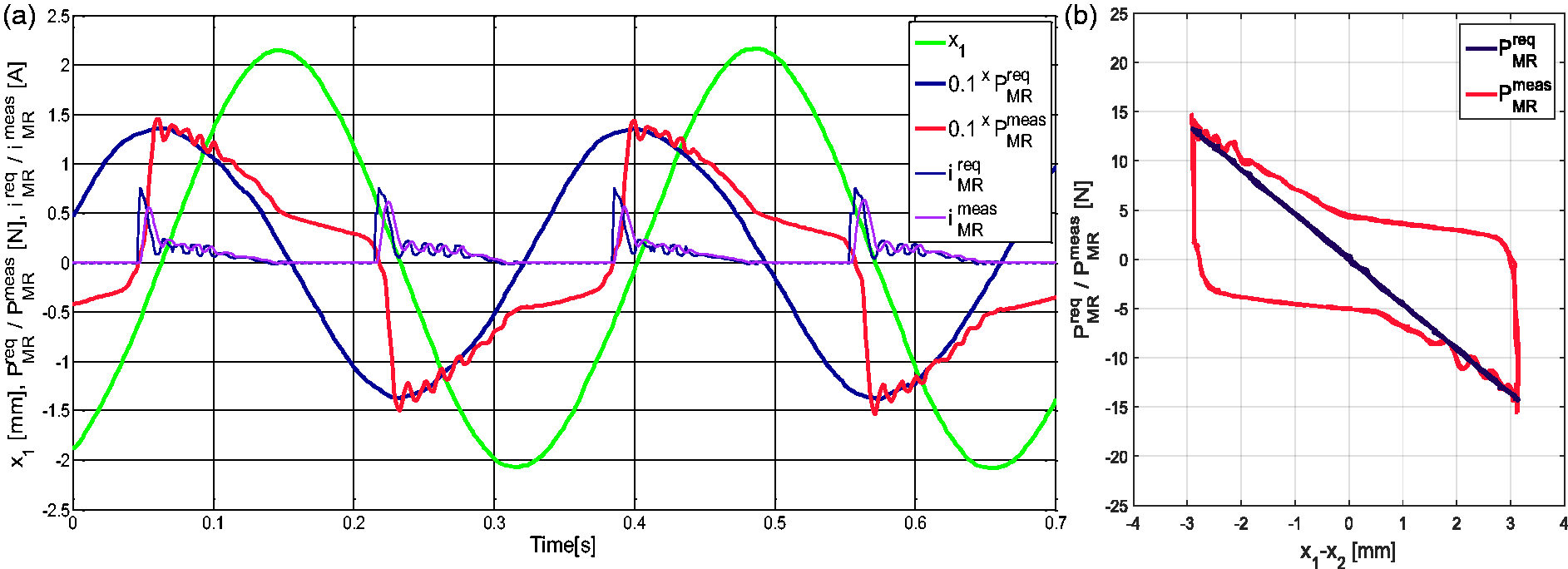
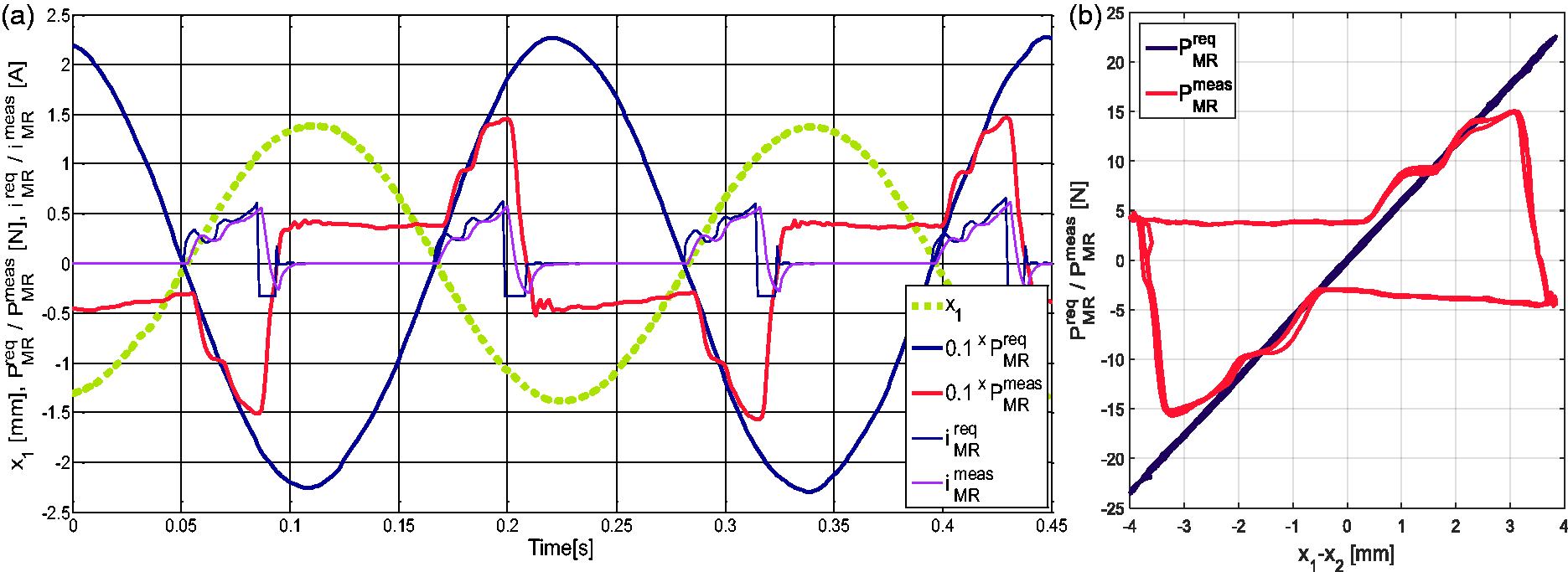
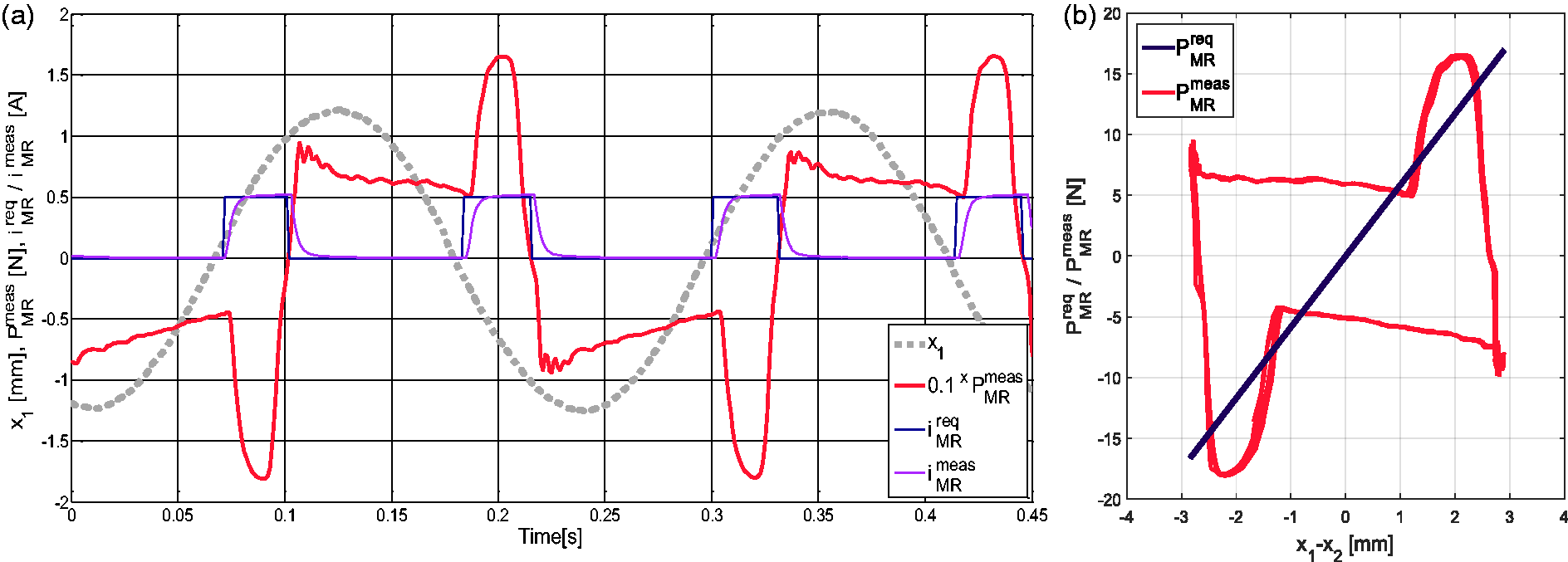
In Figure 10, two maxima that are typical for TVA operation are apparent for all the solutions but 0.2, 0.3, 0.4 and 0.5 A, for which the damping is relatively too high. Throughout all the semiactive solutions, ADPT V.1 and Mod.GND prove to be the most favourable. ADPT V.2 seems inferior to ADPT V.1 in the second maxima neighbourhood (while ADPT V.1 is marginally worse in the first maxima neighbourhood than ADPT V.2), however comparison of Figures 18 to 20 may result in the conclusion, that (offen chosen) assumption of γ > 1 or some positive damping added may improve the system response (as higher amplitude of PMRmeas seems more appropriate at 4.35 Hz - see also Figure 10); along with the increase of PMRreq, ADPT V.2 may become a preferred choice as it copes better with the integrator wind-up (by changing the value of γ, either the first maxima is lowered while the second maxima is elevated, or the second is lowered while the first – elevated). Both, ADPT V.1 and ADPT V.2 are superior to the previously introduced24–26,31,32,37 ADPT PI, and especially to ADPT INV, within the first and the second maxima neighbourhoods (see Figure 10 and Table 2). The MR damper required force PMRreq (that is the same for each of the ADPT algorithms) tracking at 2.95 Hz for ADPT PI and ADPT INV is inferior with respect to ADPT V.1 and ADPT V.2, especially considering the time instants immediately following PMRmeas sign changes (all presented time patterns have the same phase shifts, see Figures 11 to 14). While observing Figures 16 to 19, the difference of PMRreq force tracking precision at 4.35 Hz is more evident than at 2.95 Hz. The MR damper residual force values (just after PMRmeas sign changes) measured for ADPT PI, and especially for ADPT INV, are incomparable to the respective patterns registered for ADPT V.1 and ADPT V.2 systems (again all time patterns have the same phase shifts). The same may be concluded concerning PMRreq force tracking quality just before PMRmeas sign changes, although ADPT INV characteristics (Figure 16) could not be even described as ‘acceptable’. Concerning the MR damper residual force minimisation, both ADPT V.1 and ADPT V.2 (Figures 18 and 19) are superior to Mod.GND system (Figure 20) – the logics adopted for the demagnetisation and response sharpening do the job properly. The MR damper force-displacement loops exhibit the negative stiffness (resulting from the equations (1) and (2)) along with the friction (due to the MR damper residual force) phenomena at 2.95 Hz and the positive stiffness with the friction phenomena at 4.35 Hz. Interestingly, the MR damper measured force and current patterns obtained for Mod.GND system (Figures 15 and 20) do not differ fundamentally from the respective patterns obtained for ADPT V.1 and ADPT V.2; however, PMRmeas force-displacement loops for Mod.GND (combined with the hypothetical – as Mod.GND algorithm does not use required force pattern – PMRreq loops calculated according to equations (1) and (2) on the basis of x1–x2meas signal) indicate the additional presence of nonlinear damping.
As may be seen in (for example) Figure 18(a) zoom, the MR damper response time cannot be neglected – one may observe iMRreq signal rise at a time instant of 0.05 s, while PMRmeas response modulus rise is at ca. 0.06 s, what makes the real challenge for the follow-up-type-controller operational quality (part of that delay is iMRmeas delay, see Figure 22(a) and (b)); see also the resultant oscillations evident in Figures 13 and 14.
ADPT V.1 system at 2.95 Hz: (a) time responses and (b) MR damper force-displacement loops.
ADPT V.2 system at 2.95 Hz: (a) time responses and (b) MR damper force-displacement loops.
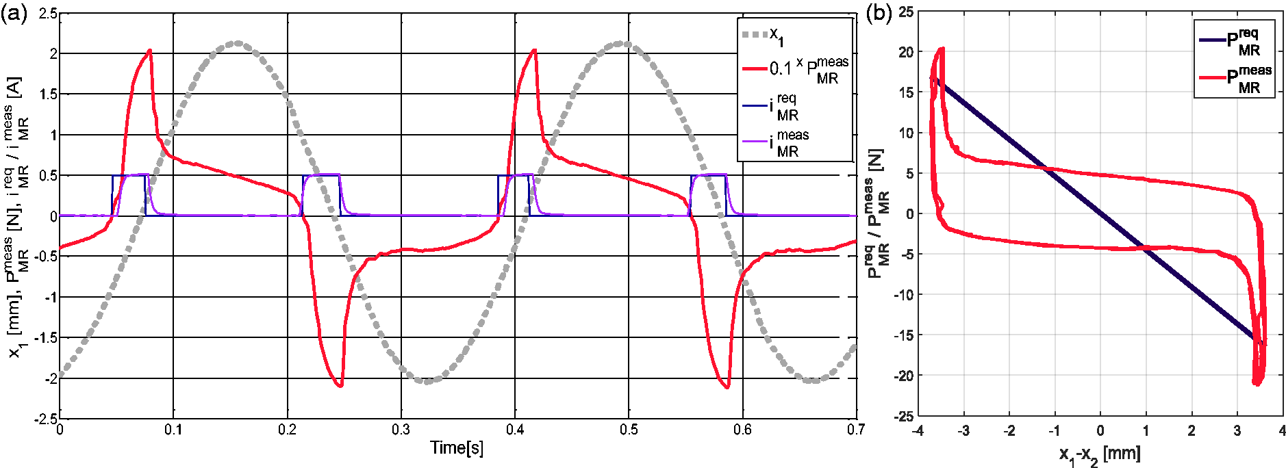
Mod.GND system at 2.95 Hz: (a) time responses and (b) MR damper force-displacement loops.

ADPT INV system at 4.35 Hz: (a) time responses and (b) MR damper force-displacement loops.
ADPT PI system at 4.35 Hz: (a) time responses and (b) MR damper force-displacement loops.
ADPT V.1 system at 4.35 Hz: (a) time responses and (b) MR damper force-displacement loops.
ADPT V.2 system at 4.35 Hz: (a) time responses and (b) MR damper force-displacement loops.
Mod.GND system at 4.35 Hz: (a) time responses and (b) MR damper force-displacement loops.
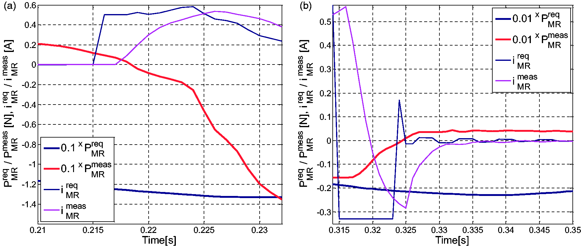
Selected time responses sections, ADPT V.2 system at: (a) 2.95 Hz and (b) 4.35 Hz.
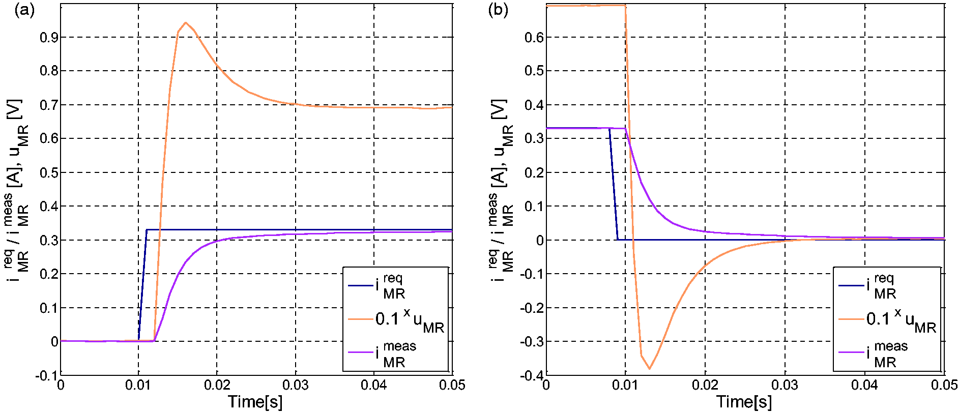
PID current controller operation at: (a) positive and (b) negative step change of iMRreq.
Conclusion
The conducted experimental analysis proved the effectiveness of the proposed refined MR damper force tracking algorithm in two versions. The obtained output frequency response function of the tower tip horizontal displacement amplitude for the ADPT V.1 system excels former solutions (designated by ADPT PI and ADPT INV) and is comparable to the frequency response of the Mod.GND system that previously demonstrated the best performance.24–26 ADPT V.1 is superior to Mod.GND in the (3.45, 4.15) Hz range, while Mod.GND excels for frequencies higher than 4.35 Hz and marginally in the (3.00, 3.20) Hz range. It was shown that the logics adopted for both ADPT V.1 and ADPT V.2 cope best with the problem of the residual MR damper force / magnetic remanence when zero force is assumed due to the MR damper inability to generate active forces. The implementation of these logics for the Mod.GND algorithm, along with the analysis of the demanded value of γ for the real-world system with response time, residual force and inherent damping, all of which are nonzero, shall be a subject of the future research. The minimisation of the residual force negative effects and the quality of positive stiffness tracking will also be investigated. Based on these analyses results, and laboratory model measurements, and considering the dynamic similarity study that includes determined time and length scale factors 41 in combination with force scale factor, 44 direct calculation of the demanded control signal for a real-world full scale vibration reduction system / MR TVA will be possible.
Footnotes
Declaration of conflicting interests
The author(s) declared no potential conflicts of interest with respect to the research, authorship, and/or publication of this article.
Funding
The author(s) disclosed receipt of the following financial support for the research, authorship, and/or publication of this article: This work is supported by AGH University of Science and Technology under research program no. 11.11.130.958.