
Abstract
A current-and-voltage serial-model stator flux estimator, based on fuzzy logic control for a speed estimation stator flux vector-controlled induction motor drive, is proposed in this study. Stator current and flux was used to establish direct stator flux vector-controlled induction motor drive and the estimated synchronous speed was derived from the developed voltage-and-current serial-model stator flux estimator. The estimated rotor speed was acquired by subtracting the slip speed from the estimated synchronous speed. The adaptation mechanism of this flux estimator was designed using the fuzzy logic control approach because it is simple and suitable for use under variable conditions. This system was simulated using the MATLAB\Simulink toolbox and all the control algorithms were realized by an RX62T microcontroller. Both simulation and experimental results confirmed the effectiveness of the proposed approach.
Keywords
Introduction
Intelligent precision machine tools demand high performance motor drives and induction motors (IMs) are used almost exclusively for this purpose nowadays. IMs are robust, can be totally enclosed, require little maintenance, and are usually small and inexpensive. The behavior of an IM can be represented by a differential equation model, with of two stator state variables, two rotor state variables, and shaft speed. Two more variables are involved in the computational process. The variation iteration method or homotopy perturbation method1–6 can be used to solve the linear and nonlinear systems of the differential equations. These approximating techniques are also employed to solve linear or nonlinear boundary value problems. The mathematical model of an IM is complicated and this makes IM drives more difficult to control than DC motor drives. Utilization of the flux vector control (FVC) technique and using Laplace transformation7,8 allows a time-variant, nonlinear coupled mathematical model of an IM to be transformed into one that has both torque and flux current components. 9 Both components are orthogonal and can be independently controlled. Such a condition is analogous to a separately excited DC motor and a maximum torque–current ratio can be attained. The FVC approach to IM drive control can in general be classified as direct or indirect. 10 In the direct FVC approach, the position and magnitude of the flux can be directly estimated based on the measured motor currents and voltages. In the indirect FVC approach, the rotor position and estimated slip angle are used to calculate the flux position. Implementation of a traditional FVC IM drive requires a rotor shaft position sensor such as an encoder to detect rotor position. However, this makes the system less robust and unsuitable for use in a hostile environment. A number of speed estimation methods for FVC IM drives have been devised: a rotor speed adjustment mechanism that uses an extended Kalman filter,11–14 a model reference adaptive system that determines the motor shaft speed online,15–18 a neural network that tunes the rotor speed,19–22 and a speed estimation scheme that uses a flux observer.23–26 In this study a speed estimation approach is proposed that has advantages over these other methods in that control is easy and stable. The traditional current-model stator flux estimator is affected by variations in rotor resistance at low speed and by variations in rotor resistance and mutual inductance at high speed. The traditional voltage-model stator flux estimator is affected by variations in stator resistance and the magnitude of the stator voltage at low speed, but is less affected by variations of the motor parameters at high speed. 10 The current-and-voltage serial-model stator flux estimator has an advantage in that it is less affected by variations of motor parameters and the running speed range can also be extended. In this system, the direct stator flux vector-controlled induction motor (SFVC IM) drive was established by using the current and flux of the stator. The current-and-voltage series-model stator flux estimator was used to estimate the synchronous speed and the estimated rotor speed was acquired by subtracting the slip speed from the estimated synchronous speed. The adaptation mechanism of this estimator was designed using a fuzzy logic control (FLC) scheme.
SFVC IM drive
The vector state equations of an IM at the synchronous reference coordinate frame are
10


Under an SFVC condition, set

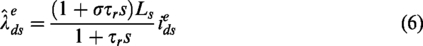
The linear control relation between the flux and current of the d-axis stator can be derived from
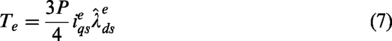
The electromagnetic torque under an SFVC condition is derived from

Under an SFVC condition, according to equation (2), the d-axis and q-axis stator voltage are expressed as


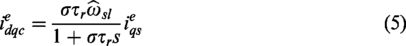
Inspection of equation (10) reveals that the linear control of the d-axis stator current loop is inherent, and equation (11) reveals the voltage coupling in the second term on the right side. This allowance definition of feed-forward compensation is


Current-and-voltage serial-model stator flux estimator based on an FLC approach
The estimated rotor speed of this system was obtained by subtracting the estimated slip speed from the estimated synchronous speed, and this synchronous speed was derived from the developed current-and-voltage serial-model stator flux estimator.
Current-and-voltage serial-model stator flux estimator
The stator and rotor voltage vector equations of an IM at stationary reference coordinate frame (


The stator and rotor flux vectors are given by


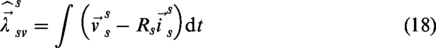
In accordance with equation (14), the voltage-model stator flux estimator is developed as
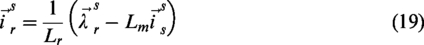
Utilization of equation (17) allows the rotor current vector to be expressed as a function of the rotor flux and stator current vectors as
And substitution of equation (19) into equations (15) and (16) allows the rotor flux and stator flux vectors to be expressed as
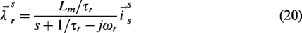
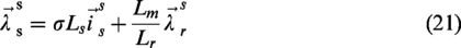
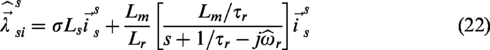
Then, substituting equation (20) into equation (21), the current-model stator flux estimator is developed as
The proposed current-and-voltage serial-model stator flux estimator is shown in Figure 1. Here the difference between the current- and voltage-model stator flux estimators is employed using an adjustment mechanism to obtain voltage
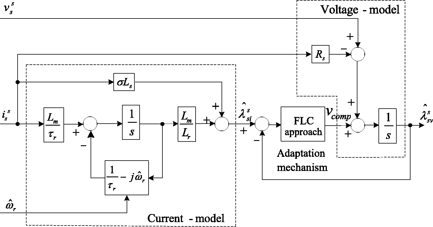
Current-and-voltage serial-model stator flux estimator. FLC: fuzzy logic control.
The synchronous angle position
Rotor speed estimation
Because
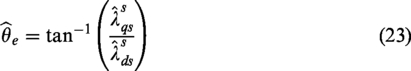
The estimated synchronous angle speed is derived by differentiating equation (23) with respect to the time variable from
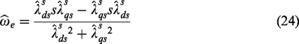
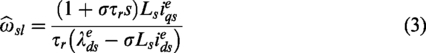
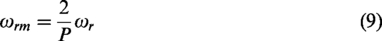
By utilizing equations (24) and (3), the estimated rotor speed can be obtained as

Design of an FLC based adaptation mechanism
FLC can be regarded as the application of linguistically imprecise knowledge from human experts and the behavioral characters of the plant. In accordance with the linguistic rule, the definite quantification input signals through fuzzy inference decide the fuzzy output signals, and these signals are then converted to definite quantities for drive control. An adaptation mechanism based on an FLC approach has advantages over the conventional proportion integral (PI) type in that the scheme is simple, easy to implement, and requires no precise information about the mathematical model.
27
An FLC adaptation mechanism includes fuzzification, a fuzzy knowledge base, fuzzy inference, and defuzzification.
28
The fuzzy knowledge base also has a fuzzy set and rule base and these are shown in Figure 2. The flux error
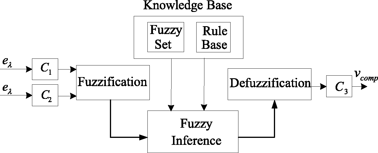
An FLC adaptation mechanism.
The basic steps in the design of an FLC adaptation mechanism are fuzzification, fuzzy inference, the fuzzy rule, and defuzzification.
Fuzzification
The fuzzification function converts the crisp input values into corresponding fuzzy values, and the numbers of fuzzy sets determine the compensation voltage of the voltage-model flux estimator. In this system, the fuzzy set is defined as positive large (PL), positive small (PS), zero error (ZE), negative small (NS), and negative large (NL), as shown in Table 1.
Definitions of the fuzzy set.

The membership functions for the flux error (
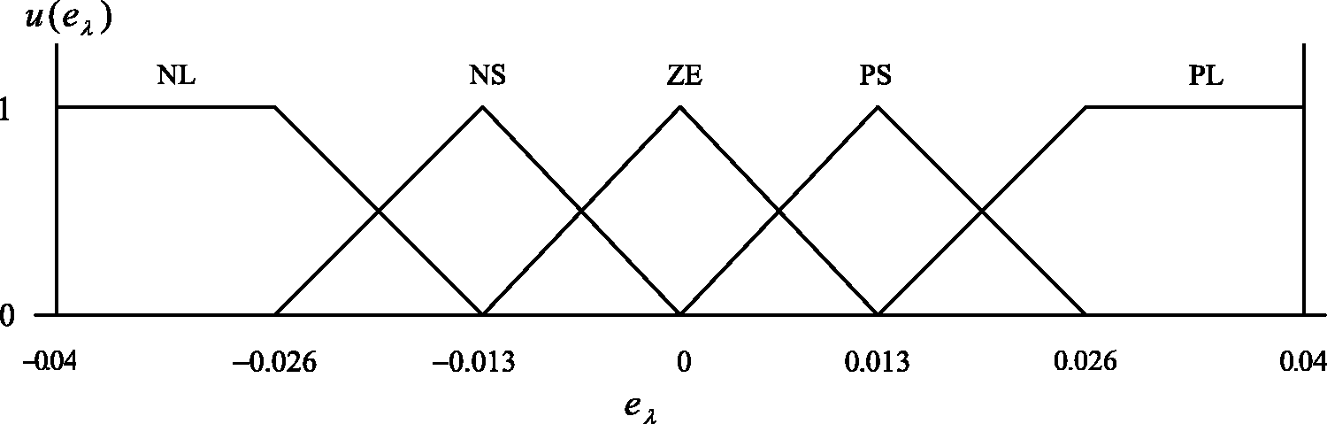
The membership function of
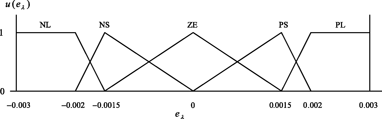
The membership function of
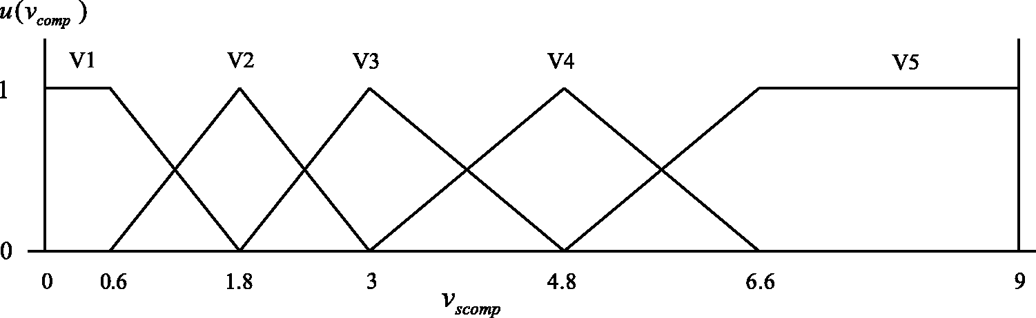
The membership function of
Fuzzy inference
The output characteristic is determined by the fuzzy rule and the output measure is based on fuzzy inference. The Min–Min–Max approach is used to decide fuzzy inference. The fuzzification step is regarded as the first Min term that uses minimum trigger as the membership grade. The output membership grade of each fuzzy inference rule is regarded as the second Min term that selects the minimum value from the two input membership grades based on the fuzzy inference rules. The maximum value approached from the same output membership functions integrated into an individual rule is regarded as the third Max term.
Fuzzy rule
The trigger for the output membership function is decided by the fuzzy rule; in this system the linguistic term if-then has been selected as the fuzzy rule. The relationship between the input variables,
Rule 1: IF
Rule 2: IF
⋮
Rule 13: IF
⋮
Rule 24: IF
Rule 25: IF
The 25 rules are listed in Table 2.
The fuzzy rule table.
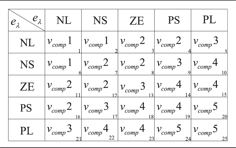
NL: negative large; NS: negative small; PL: positive large; PS: positive small; ZE: zero error.
Defuzzification
Defuzzification converts inferred fuzzy output into crisp output value, which is used to control the drive. In this system, the central value of the defuzzification sum approach is used, giving
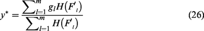
where
Simulation and experimental
The block diagram of the proposed FLC flux estimator-based speed estimation SFVC IM drive is shown in Figure 6 and includes the speed controller, flux controller, q-axis and d-axis stator current controllers, d-axis stator flux decoupling, q-axis stator voltage decoupling, estimated synchronous speed and estimated rotor speed, coordinate transformation, and an FLC-based current-and-voltage serial-model stator flux estimator. In this system, the PI-type controllers for the speed control loop, flux control loop, d-axis, and q-axis stator current control loops were designed using the root locus method. The adjustment mechanism of the current-and-voltage serial-model stator flux estimator was designed using an FLC approach.
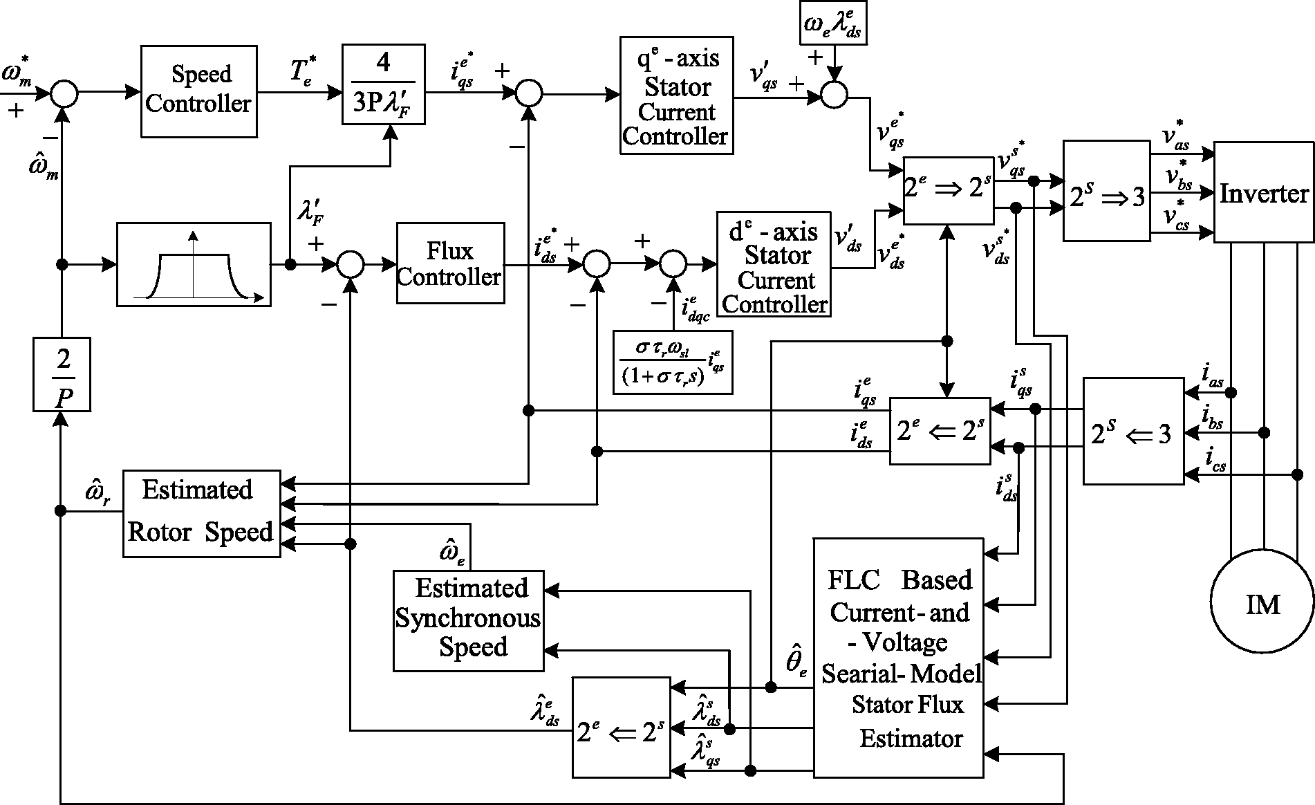
FLC current-and-voltage serial-model stator flux estimator-based speed estimation SFVC IM drive. FLC: fuzzy logic control.
A standard three-phase, 220 V, 0.75 kW, Δ-connected, squirrel-cage IM was used in experiments to confirm the effectiveness of the proposed speed estimation SFVC IM drive. In the running cycle tests, the speed commands were as follows: forward direction acceleration from
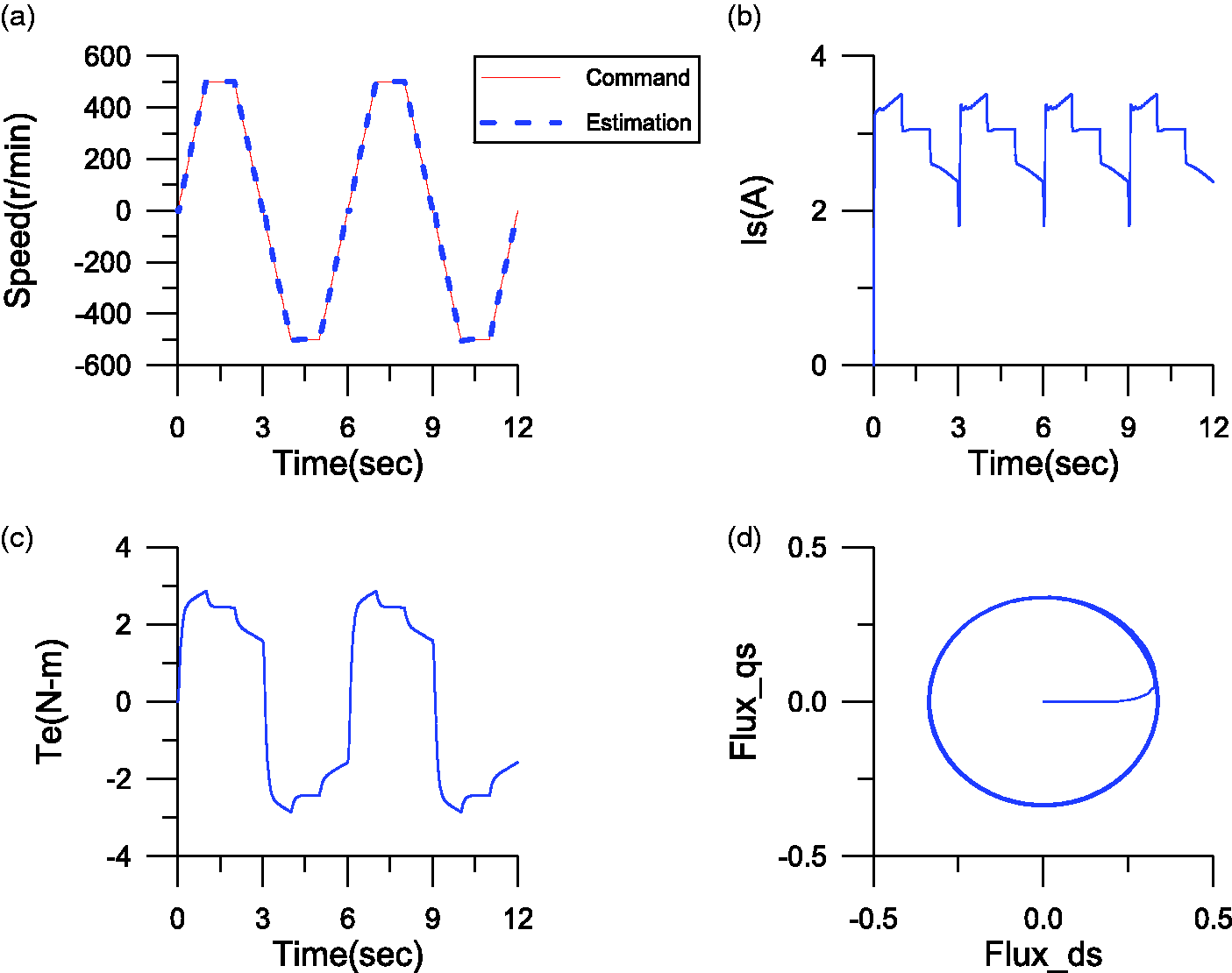
Simulated responses of the FLC flux estimator-based speed estimation SFVC IM drive with a 2 N m load and speed command ±500 r/min: (a) command (solid line) and estimated (dotted line) rotor shaft speed, (b) stator current, (c) estimated electromagnetic torque, and (d) stator flux locus (q-axis versus d-axis).
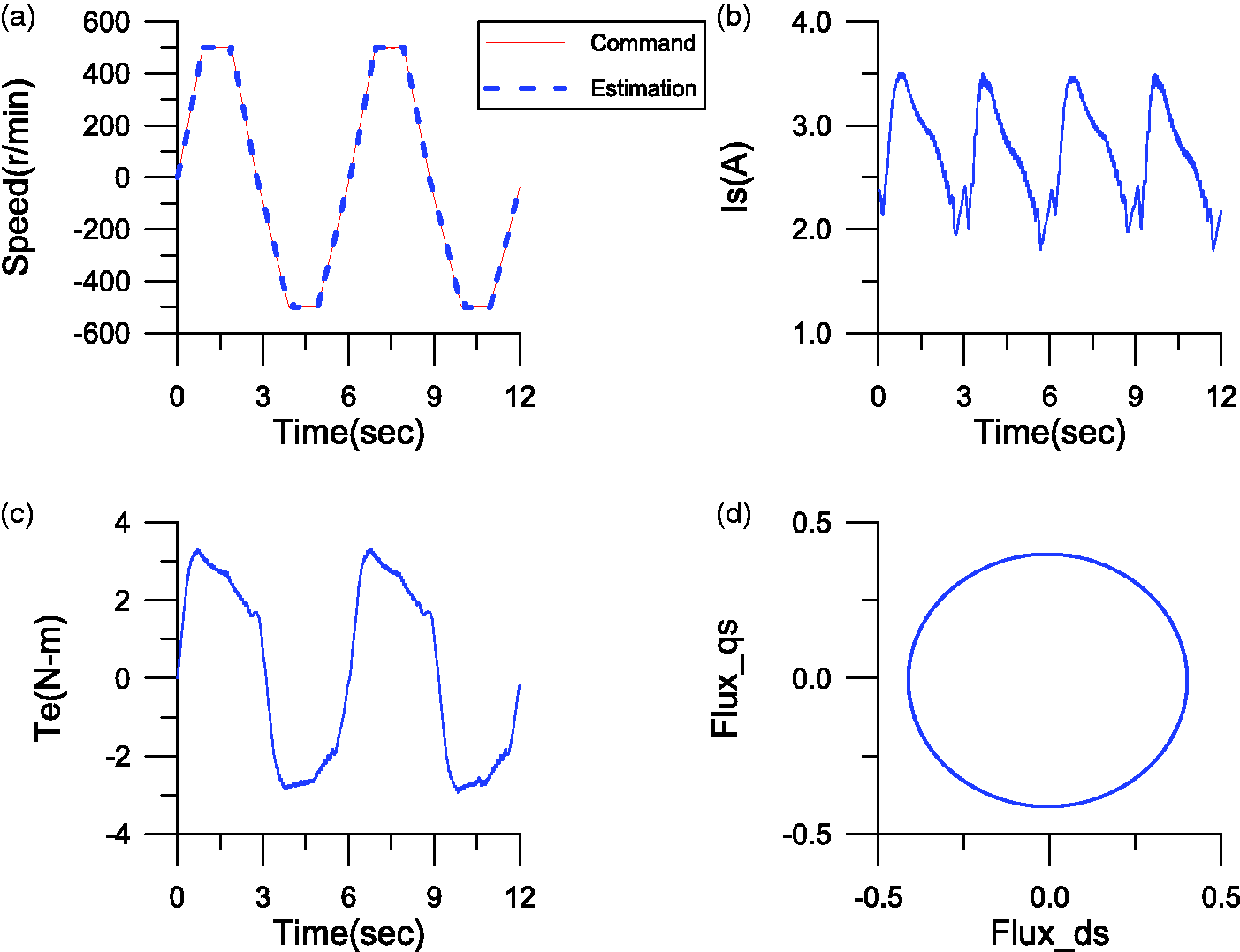
Measured responses of the FLC flux estimator-based speed estimation SFVC IM drive with a 2 N m load and speed command ±500 r/min: (a) command (solid line) and estimated (dotted line) rotor shaft speed, (b) stator current, (c) estimated electromagnetic torque, and (d) stator flux locus (q-axis versus d-axis).
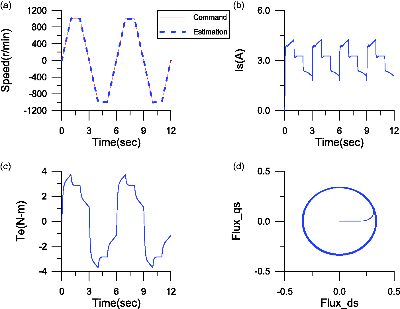
Simulated responses of the FLC flux estimator-based speed estimation SFVC IM drive with a 2 N m load and speed command ±1000 r/min: (a) command (solid line) and estimated (dotted line) rotor shaft speed, (b) stator current, (c) estimated electromagnetic torque, and (d) stator flux locus (q-axis versus d-axis).
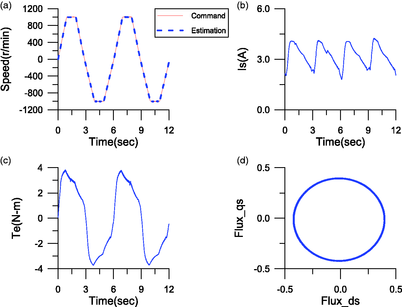
Measured responses of the FLC flux estimator-based speed estimation SFVC IM drive with a 2 N m load and speed command ±1000 r/min: (a) command (solid line) and estimated (dotted line) rotor shaft speed, (b) stator current, (c) estimated electromagnetic torque, and (d) stator flux locus (q-axis versus d-axis).
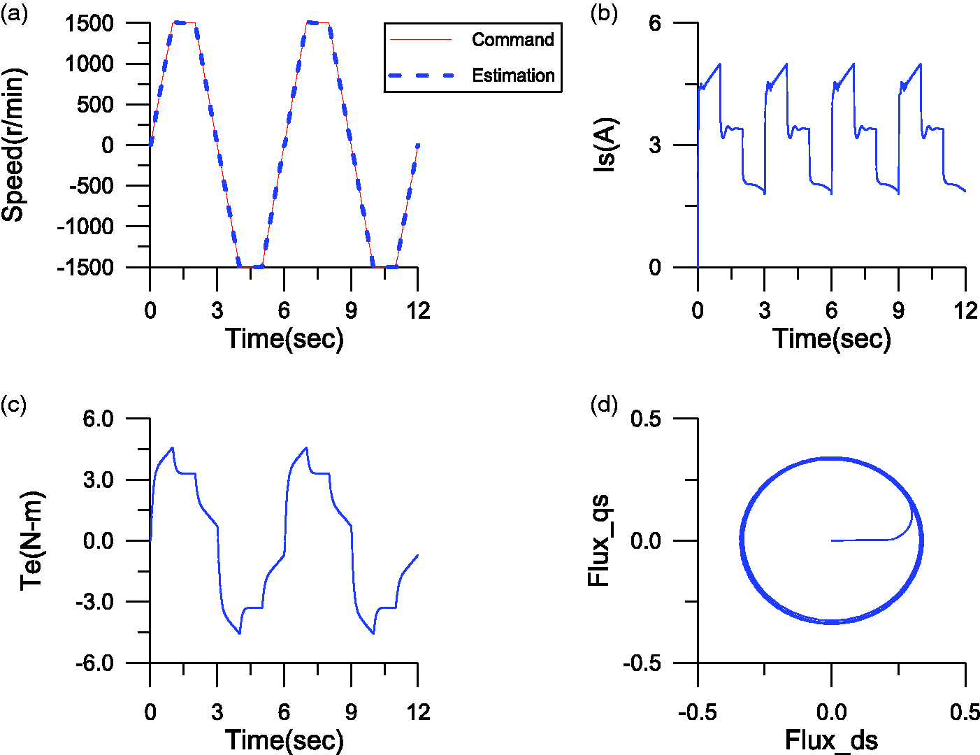
Simulated responses of the FLC flux estimator-based speed estimation SFVC IM drive with a 2 N m load and speed command ±1500 r/min: (a) command (solid line) and estimated (dotted line) rotor shaft speed, (b) stator current, (c) estimated electromagnetic torque, and (d) stator flux locus (q-axis versus d-axis).
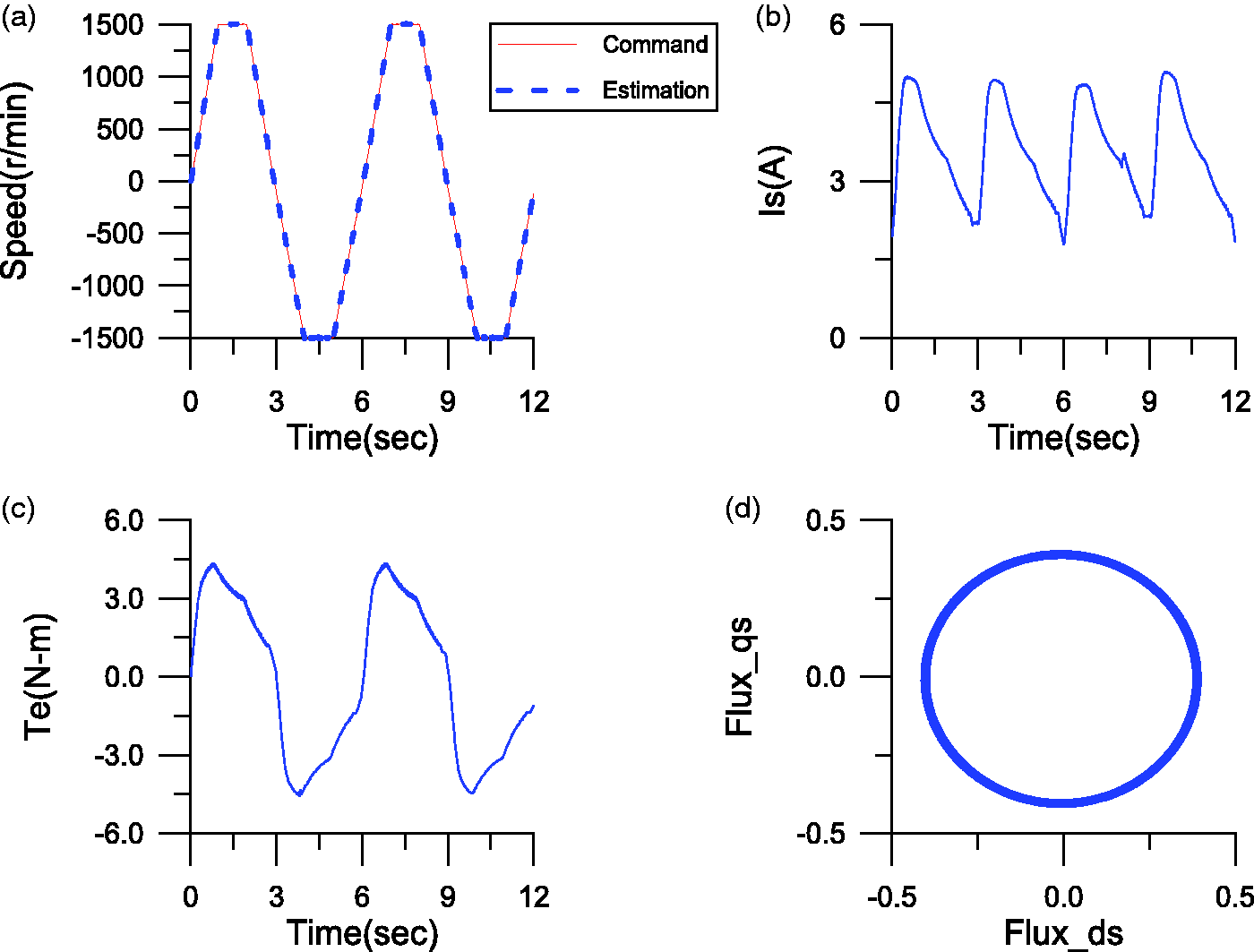
Measured responses of the FLC flux estimator-based speed estimation SFVC IM drive with a 2 N m load and speed command ±1500 r/min: (a) command (solid line) and estimated (dotted line) rotor shaft speed, (b) stator current, (c) estimated electromagnetic torque, and (d) stator flux locus (q-axis versus d-axis).
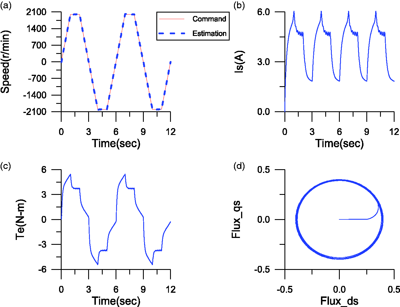
Simulated responses of the FLC flux estimator-based speed estimation SFVC IM drive with a 2 N m load and speed command ±2000 r/min: (a) command (solid line) and estimated (dotted line) rotor shaft speed, (b) stator current, (c) estimated electromagnetic torque, and (d) stator flux locus (q-axis versus d-axis).
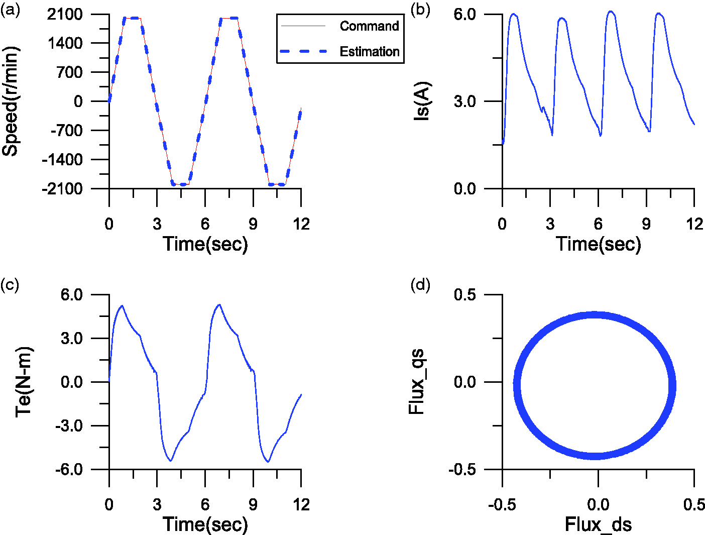
Measured responses of the FLC flux estimator-based speed estimation SFVC IM drive with a 2 N m load and speed command ±2000 r/min: (a) command (solid line) and estimated (dotted line) rotor shaft speed, (b) stator current, (c) estimated electromagnetic torque, and (d) stator flux locus (q-axis versus d-axis).
Accuracy estimations of the reversible rotation speed were obtained using simulations and experimental results for different speeds (see Figures 7 to 14). The circular shape of the estimated stator flux locus shows the estimated synchronous angle position for execution coordinate transformation to be exact, and the stator current and electromagnetic torque showed excellent response. Very good performance could clearly be achieved with the proposed FLC current-and-voltage serial-model stator flux-based speed estimation SFVC IM drive.
Conclusions
This study describes the design of an application that uses the current-and-voltage serial-model stator flux estimator, in a FLC approach, for the speed estimation of SFVC IM drives. The estimated speed derived from the current-and-voltage serial-model stator flux estimator guarantees correct operating speed within both low- and high-speed ranges. The adaptation mechanism was designed using FLC and has the advantages of simplicity and ease of implementation, the issue of instability is also avoided. The simulation and experimental responses for the estimated rotor shaft speed, stator current, estimated electromagnetic torque, and stator flux locus at different reversible steady-state speeds (±500, ±1000, ±1500, and ±2000 r/min) confirmed the effectiveness of the proposed approach.
Footnotes
Declaration of conflicting interests
The author(s) declared no potential conflicts of interest with respect to the research, authorship, and/or publication of this article.
Funding
The author(s) received no financial support for the research, authorship, and/or publication of this article.