
Abstract
In this paper, we propose the application of a speed estimation strategy to a fuzzy logic control flux estimator for a sensorless adaptive rotor flux direct-vector-controlled (RFDVC) induction motor drive. The RFDVC induction motor drive was established using the stator current and rotor flux, with the stator current being obtained from the induction motor. The model reference adaptive system (MRAS) theory was utilized to develop an adaptive rotor flux estimator based on voltage-model and current-model flux estimators. The estimated rotor speed and synchronous angle position are derived from the adaptive flux estimator. The adjustment mechanism of this estimator was designed using the fuzzy logic control strategy because this scheme is simple, easy to implement, and requires no precise information about the mathematical model. The MATLAB/Simulink® toolbox was used to simulate this system, and all the control algorithms were realized using a TI 6713-and-F2812 DSP card to validate this approach. Both the simulation and experimental results (including the estimated rotor speed, electromagnetic torque, and stator flux locus) confirmed the effectiveness of the proposed system and thereby validate the proposed approach.
Keywords
Introduction
The development of a precise manufacturing technology demands the use of many motors that exhibit superior performance to actuate machine tools. Induction motors (IMs) are generally used because of their robustness, low volume, and few maintenance requirements. However, their nonlinear, coupling, and time-varying mathematical models complicate the control of an IM drive more than that of a DC motor drive. By utilizing the flux vector control (FVC) theory of AC motors, 1 the complicated mathematical model of an IM can be transformed into flux-current and torque-current components, both of which are orthogonal and can be independently controlled. This condition is similar to a separately excited DC motor, so a maximum torque-to-current ratio can be achieved. The realization of an FVC IM drive requires a shaft-position sensor, such as an encoder or a revolver, to detect the shaft position. This sensor, however, reduces the robustness of the motor and is unsuitable for aggressive environmental conditions. Hence, the development and use of speed sensorless FVC IM drives are required to replace shaft-position-detection-type FVC IM drives. According to the literature, a number of speed estimation methods for sensorless IM drives have been developed: speed estimation by the adoption of a flux estimator or observer,2–5 speed adjustment by the utilization of a fuzzy logic control (FLC) approach or a neural network,6–9 speed determination by an adaptive control system,10–13 and speed identification by the use of an extended Kalman filter.14–17
Variable-speed motor drives have constant-torque and constant-power operation modes. In the constant-torque operation mode, the available speed of operation ranges from a standstill to the base speed. By setting the reference flux to the base value, the available output power is proportional to the motor speed. In the constant-power operation mode, the available operation speed ranges from the base speed to the maximum speed, and setting the reference flux to decrease with an increase in motor speed subsequently results in a decrease in the available output torque. In this study, we established the proposed RFDVC IM drive based on the stator current and the rotor flux. The MRAS theory was utilized to develop an adaptive rotor flux estimator based on voltage-model and current-model flux estimators, and the estimated rotor speed and synchronous angle position are derived from the adaptive rotor flux estimator. The adjustment mechanism of the adaptive rotor flux estimator was designed using the FLC strategy. The available operation speed can be extended to the constant-power mode by applying the field weakening technique. The developed adaptive rotor flux estimator guarantees an accurately estimated rotor speed and an exactly estimated synchronous angle position for the realization of a perfect sensorless RFDVC IM drive.
Direct rotor flux vector-controlled IM drive
The stator and rotor voltage vector equations for an IM in the synchronous reference coordinate frame from
18
are as follows


Under an RFDVC condition, we set

We also set


An inspection of equation (6) shows that the second and third terms on the left side are the coupling components in relation to the estimated d-axis rotor flux and the q-axis stator current, respectively. Also, the inspection of equation (7) shows that the first and third terms on the left side are the coupling components in relation to the estimated d-axis rotor flux and the d-axis stator current, respectively. These coupling components enable the following definitions of the d-axis and q-axis stator voltage feed-forward compensations
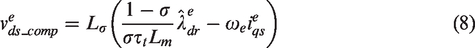
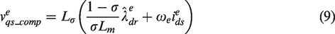
The voltage commands of the d-axis and q-axis stator-current control loops are derived as follows


By the utilization of equations (6) and (8) and equations (7) and (9), respectively, the plant equations of the d-axis and q-axis stator-current control loops are given, respectively, as follows
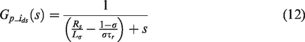
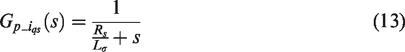
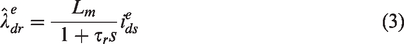
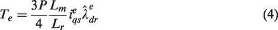
Since the bandwidths of the stator-current control loops are much higher than those of the flux and speed control loops, the closed-loop gain of the stator-current control loops can be regarded as a unit. According to equations (3) and (5), the plant equations of the flux and speed control loops are, respectively, given as follows
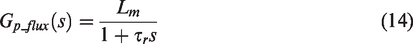
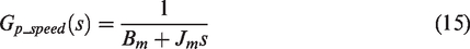
Figure 1 shows a linear control block diagram of an IM based on the RFDVC condition. Here, the paired parameters (
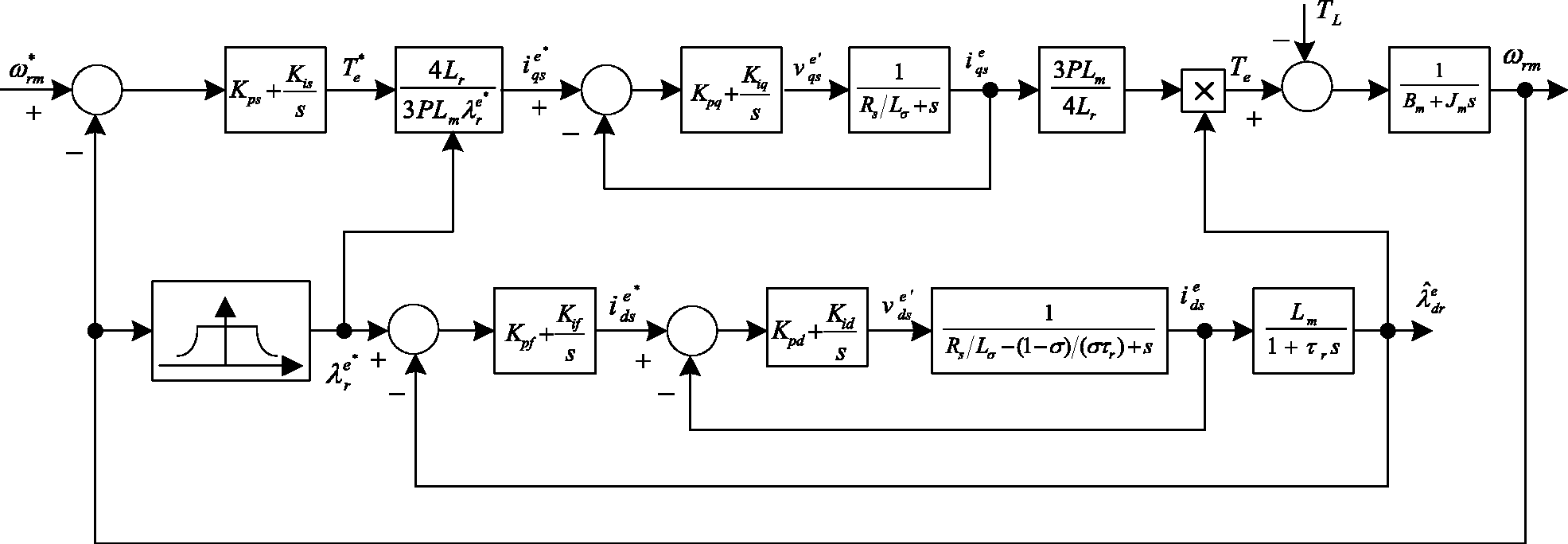
Block diagram of linear control RFDVC IM drive.
Synchronous angle position identification
The implementation of a direct vector-controlled IM drive requires the exact synchronous angle position for the coordinate transformation between a synchronous and stationary reference coordinate frame. In this study, we obtained the RFDVC IM drive based on the estimation theorem by application of the measured voltages and currents of an IM to directly calculate the magnitude and position of the rotor flux. Then, we obtained the estimated synchronous angle position from the current-and-voltage series-model rotor flux estimator.
According to equations (1) and (2), the state equations both of the stator current and the rotor flux at the stationary reference coordinate frame are as follows

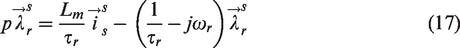
According to equation (17), the following current-model rotor flux estimator can be defined
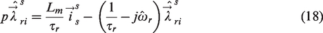
Furthermore, by utilizing equations (16) and (18), the following voltage-model rotor flux estimator can be defined

The current-and-voltage series-model rotor flux estimator is shown in Figure 2, and the difference between the outputs of the current-model and the voltage-model rotor flux estimator is used in an adjustment mechanism to derive the compensation voltage
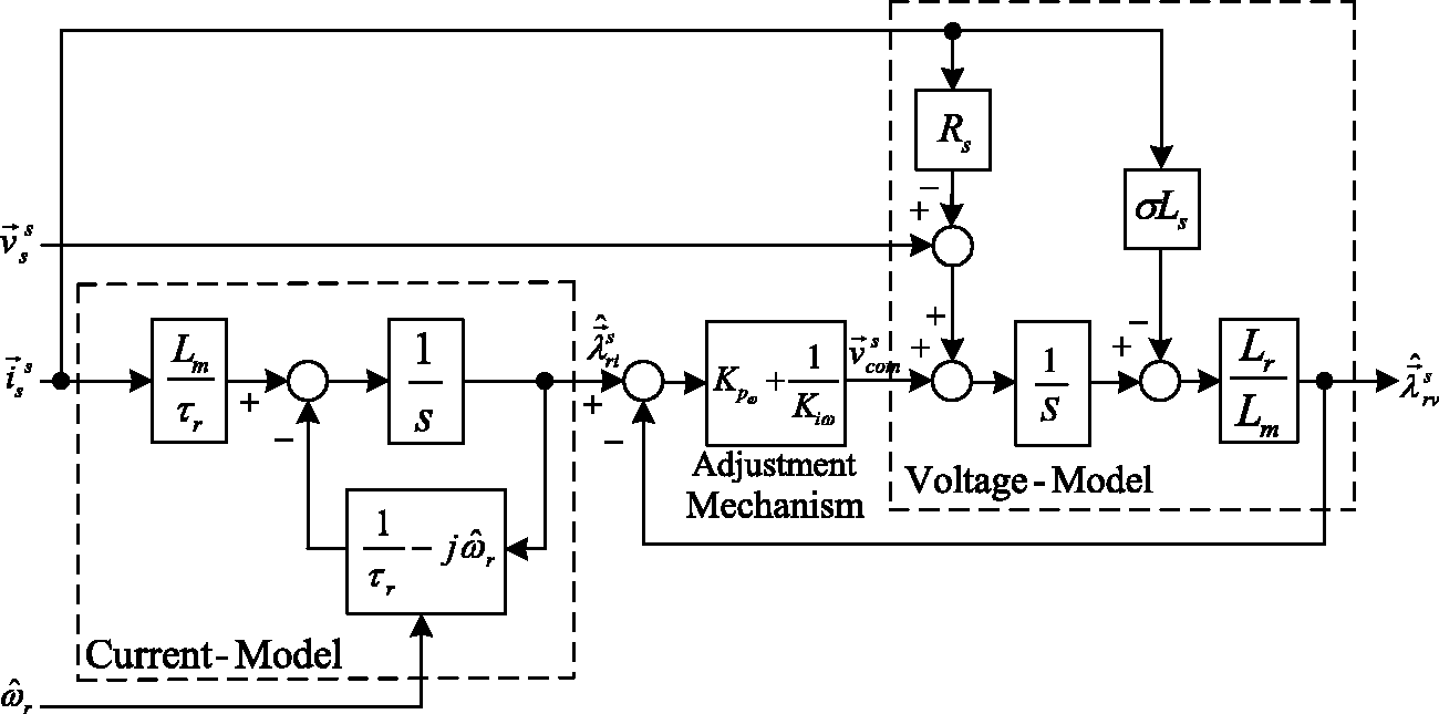
Current-and-voltage series-model rotor-flux estimator.
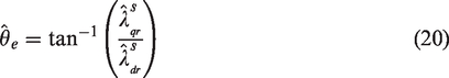
As shown in Figure 2, the synchronous angle position for realizing the coordinated transformation between synchronous and stationary reference coordinate frames is given by
A speed estimation scheme of an RFDVC IM drive
In the speed estimation RFDVC IM drive scheme, the feedback speed is replaced by a speed estimation signal, and this signal can be derived from the designed adaptive rotor flux estimator.
MRAS speed estimation scheme based on the rotor flux estimator
In the proposed sensorless RFDVC IM drive, the estimated rotor speed is derived using an MRAS speed estimation scheme based on the current-model and voltage-model rotor flux estimator. This approach guarantees the best performance of the sensorless RFDVC IM drive.
According to the MRAS theory,
19
equation (18) can be used as the adjustable model because it contains the estimated rotor speed

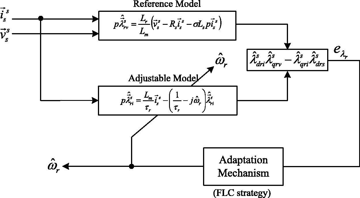
MRAS-estimated rotor speed scheme based on the rotor flux estimator.
FLC adaptation mechanism design
FLC is regarded as the application of linguistically imprecise knowledge from human experts and the behavioral characteristics of a plant. According to the linguistic rule, definite quantification input signals via fuzzy inference determine the fuzzy output signals, and these signals are transformed into definite quantities to achieve plant control. An adaptation mechanism based on an FLC approach has advantages over the conventional proportional–integral (P–I) type approach in that the scheme is simple, easy to implement, and requires no precise information about the mathematical model.
20
An FLC adaptation mechanism necessarily includes fuzzification, a fuzzy knowledge base, fuzzy inference, and defuzzification.
20
The fuzzy knowledge base also has a fuzzy set and rule base, as shown in Figure 4. The flux error
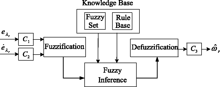
An FLC adaptation mechanism.
The basic steps in the design of an FLC adaptation mechanism, then, are fuzzification, fuzzy inference, the fuzzy rule, and defuzzification.
Fuzzification
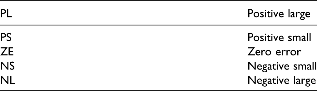
The fuzzification function converts crisp input values into corresponding fuzzy values, and the numbers of fuzzy sets determine the estimated rotor speed. In this system, a fuzzy set can be defined as positive large (PL), positive small (PS), zero error (ZE), negative small (NS), and negative large (NL), as shown in Table 1.
Definitions of the fuzzy set.
The membership functions for the flux error (
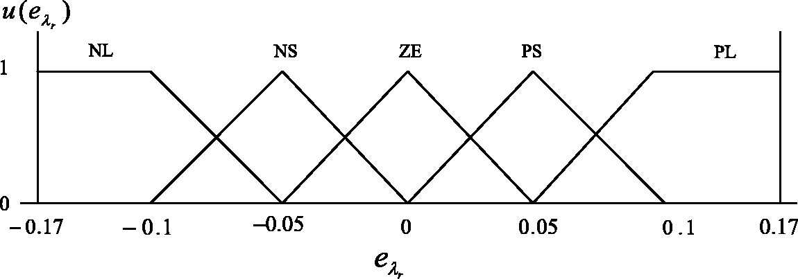
The membership function of
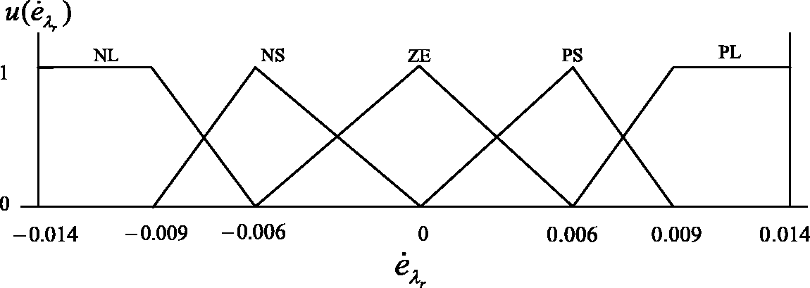
The membership function of
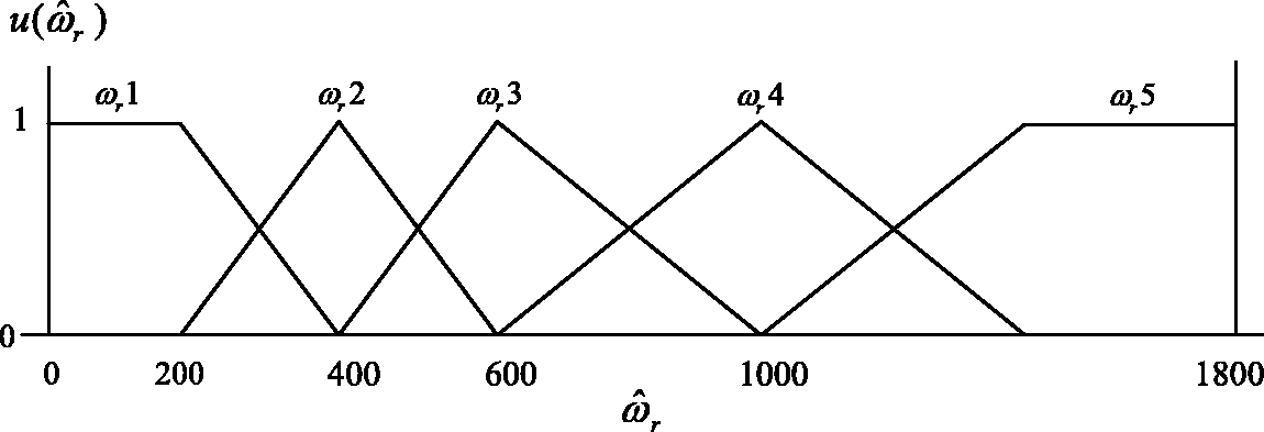
The membership function of
Fuzzy inference
The output characteristic is determined by the fuzzy rule and the output measure is based on fuzzy inference. The Min–Min–Max approach is used to determine the fuzzy inference. The fuzzification step is regarded as the first Min term and uses a minimum trigger as the membership grade. The output membership grade of each fuzzy inference rule is regarded as the second Min term, which selects the minimum value from the two input membership grades based on the fuzzy inference rules. The maximum value approached by the same output membership functions integrated into an individual rule is regarded as the third Max term.
Fuzzy rule
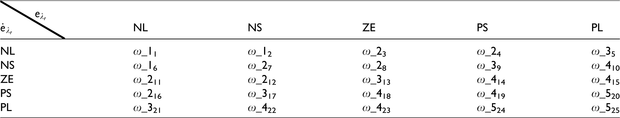
The trigger for the output membership function is decided by the fuzzy rule. In this system, the linguistic term if–then has been selected as the fuzzy rule. The relationship between the input variables,
The fuzzy rule table.
Defuzzification
Defuzzification converts inferred fuzzy output into a crisp output value, which is used to dominate the estimated rotor speed. This system uses the central value of the defuzzification sum, which gives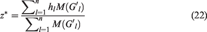
Figure 8 shows a block diagram of the proposed sensorless adaptive RFDVC IM drive based on the FLC rotor flux estimator. This system includes the following: a speed controller, flux controller, q-axis and d-axis stator-current controllers, d-axis voltage decoupling, q-axis voltage decoupling, flux command calculation, estimated d-axis flux calculation, coordinate transformation, estimated synchronous angle position based on the current-and-voltage series-model rotor-flux estimator, and the MRAS-estimated rotor speed based on the FLC strategy.
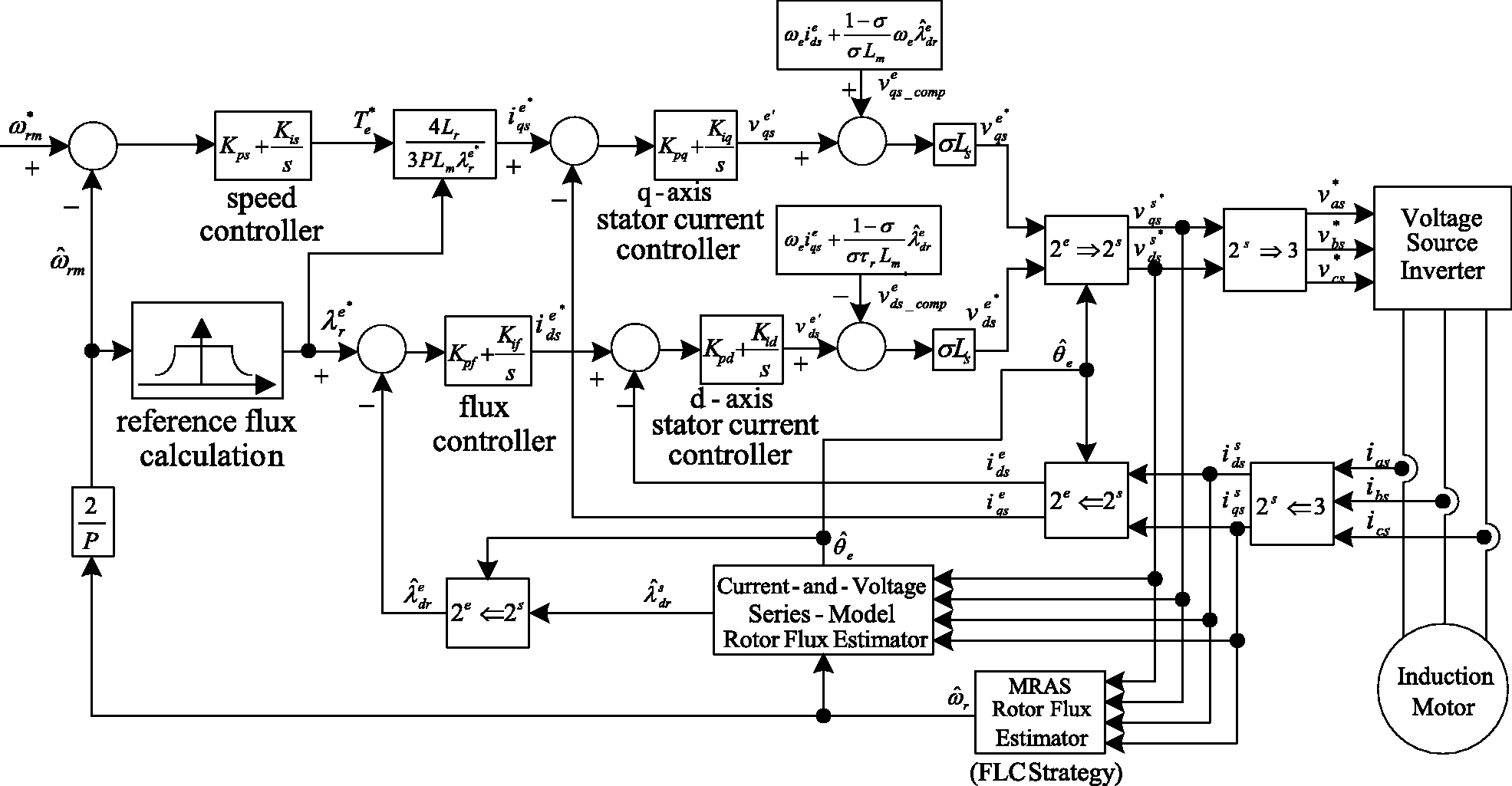
Block diagram of the proposed sensorless adaptive RFDVC IM drive based on the FLC strategy.
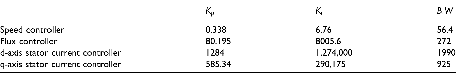
In this study, the root-locus method was used to design the P–I-type controllers for the speed control loop, flux control loop, and d-axis and q-axis stator-current control loops. Table 3 shows the proportional gain (
Controller parameters and its bandwidth.
Simulation and experimental
In the experiments, we used a standard three-phase, 220 V, 0.75 kW, Δ-connected, squirrel-cage IM to confirm the effectiveness of the proposed sensorless adaptive RFDVC IM drive based on the FLC strategy. In a running cycle, the speed command is as follows: forward-direction acceleration from
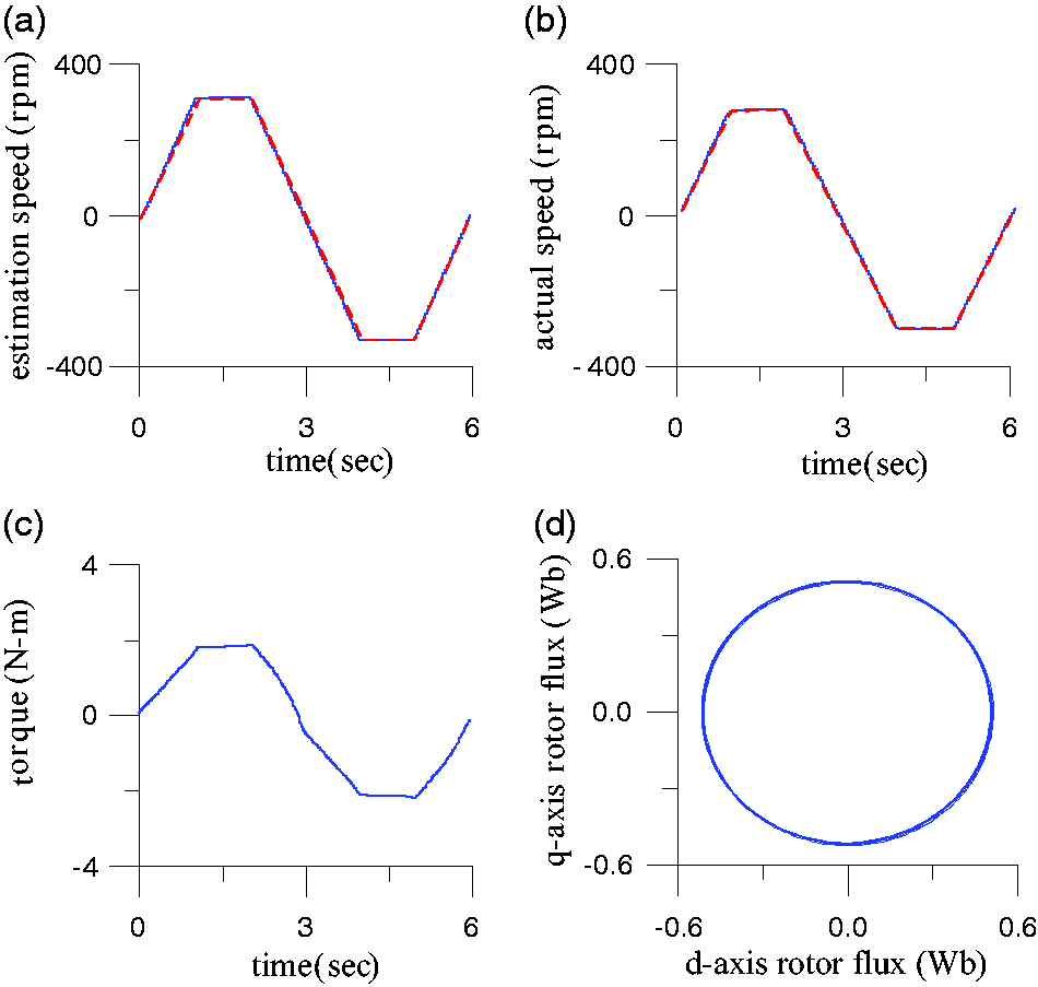
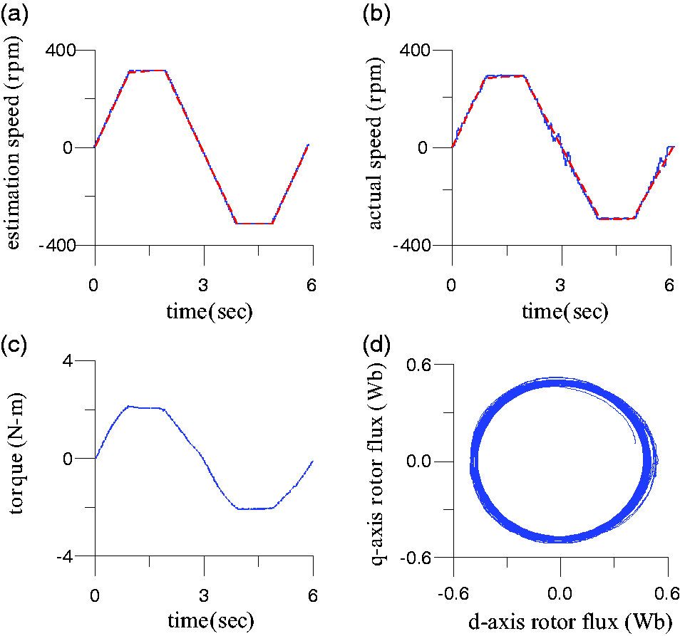
Simulated responses of the proposed sensorless adaptive RFDVC IM drive with 2 N-m load at reversible steady-state speed command ±300 r/min. (a) command speed (dotted line) and estimated rotor speed (solid line), (b) command speed (dotted line) and actual rotor speed (solid line), (c) electromagnetic torque, (d) stator flux locus (q-axis vs d-axis).
Measured responses of the proposed sensorless adaptive RFDVC IM drive with 2 N-m load at reversible steady-state speed command ±300 r/min. (a) command speed (dotted line) and estimated rotor speed (solid line), (b) command speed (dotted line) and actual rotor speed (solid line), (c) electromagnetic torque, (d) stator flux locus (q-axis vs d-axis).
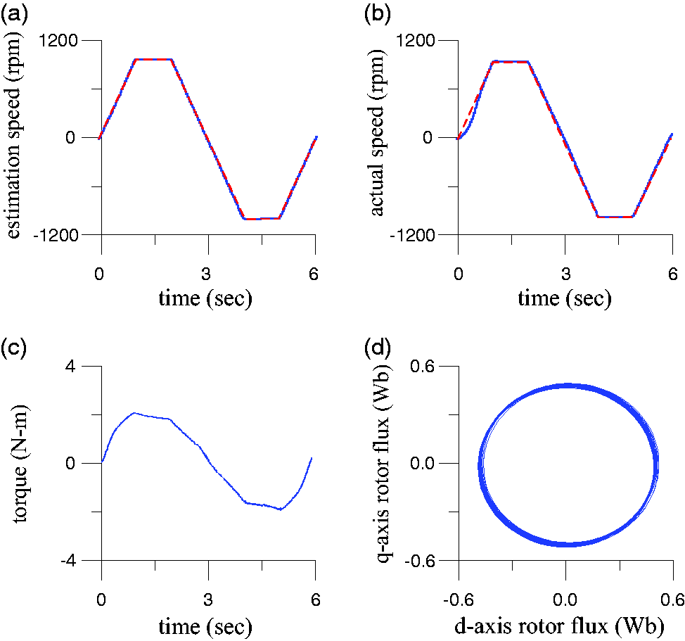
Simulated responses of the proposed sensorless adaptive RFDVC IM drive with 2 N-m load at reversible steady-state speed command ±900 r/min. (a) command speed (dotted line) and estimated rotor speed (solid line), (b) command speed (dotted line) and actual rotor speed (solid line), (c) electromagnetic torque, (d) stator flux locus (q-axis vs d-axis).
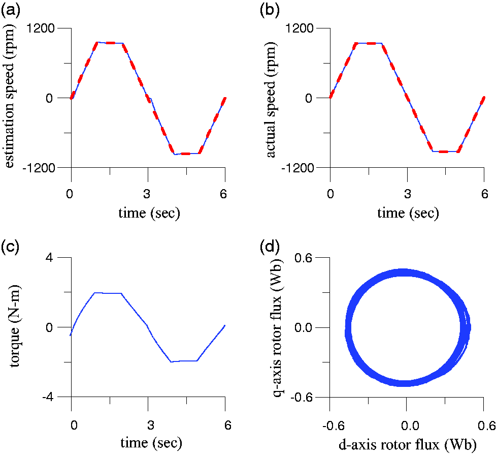
Measured responses of the proposed sensorless adaptive RFDVC IM drive with 2 N-m load at reversible steady-state speed command ±900 r/min. (a) command speed (dotted line) and estimated rotor speed (solid line), (b) command speed (dotted line) and actual rotor speed (solid line), (c) electromagnetic torque, (d) stator flux locus (q-axis vs d-axis).
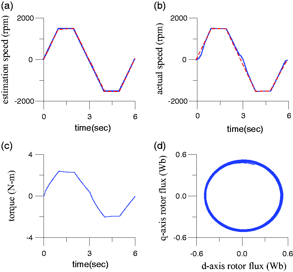
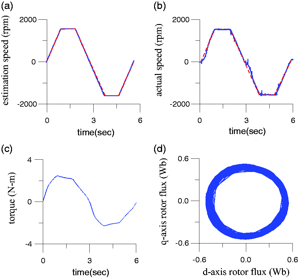
Simulated responses of the proposed sensorless adaptive RFDVC IM drive with 2 N-m load at reversible steady-state speed command ±1500 r/min. (a) command speed (dotted line) and estimated rotor speed (solid line), (b) command speed (dotted line) and actual rotor speed (solid line), (c) electromagnetic torque, (d) stator flux locus (q-axis vs d-axis).
Measured responses of the proposed sensorless adaptive RFDVC IM drive with 2 N-m load at reversible steady-state speed command ±1500 r/min. (a) command speed (dotted line) and estimated rotor speed (solid line), (b) command speed (dotted line) and actual rotor speed (solid line), (c) electromagnetic torque, (d) stator flux locus (q-axis vs d-axis).
Based on the simulated and measured results for the different operational conditions shown in Figures 9 to 14, accurately estimated rotor speeds were achieved, the electromagnetic torque attained better responses, and the circular shape of the estimated rotor flux locus verified the exactness of the coordinate transformation between the synchronous and stationary frames. Hence, the proposed sensorless adaptive RFDVC IM drive based on the FLC flux estimator demonstrated that the desired performance could be achieved.
Conclusions
In this paper, we proposed an adaptive-rotor-speed online estimation scheme that utilizes a rotor flux estimator for a sensorless RFDVC IM drive. The proposed current-and-voltage series-model rotor flux estimator acquires an estimated synchronous angle position to realize the coordinate transformation between the synchronous and stationary reference coordinate frames. This MRAS rotor-speed estimation scheme was developed based on the voltage-model and current-model rotor flux estimators, and the adaptation mechanism of the MRAS was designed using the FLC strategy. Both the simulation and experimental results, including the estimated rotor speed, electromagnetic torque, and stator flux locus, confirmed that superior performances in acceleration, steady-state, and braking operation in different reversal speed conditions can be achieved.
Footnotes
Declaration of conflicting interests
The author(s) declared no potential conflicts of interest with respect to the research, authorship, and/or publication of this article.
Funding
The author(s) received no financial support for the research, authorship, and/or publication of this article.