
Abstract
This paper presents a new composite buffer for mitigating the lateral displacement of structures under seismic loading. The buffer consists of a cylindrical rubber wrapped with fiber reinforced polymer composite. The uniaxial compressive stiffness of the buffer can be controlled by varying either the number of fiber reinforced polymer layers or the wrapping scheme of fiber reinforced polymer. First, a test program is carried out to investigate the impact of various parameters on the compressive stiffness and strength of the new buffer including thickness of fiber reinforced polymer, wrapping scheme, and method of wrapping of fiber reinforced polymer. Next, a theoretical formulation is derived to describe the constitutive behavior of fiber reinforced polymer wrapped rubber under uniaxial compression using strain energy density function of the Yeoh N-order polynomial model. Finally, a finite element model is developed to analyze the new composite buffer and the numerical results are validated using the experimental results. The results of the study show that the Yeoh model is able to simulate the behavior of rubber under compression. The new composite buffer exhibits significantly higher stiffness and strength than that of pure rubber. Wrapping scheme plays an important role in defining the mechanical behavior of the buffer. The study also shows good agreement between the numerical simulation and the experimental results.
Introduction
As an elastic material, natural rubber (NR) has been widely used in the field of earthquake engineering primarily as seismic isolation material. Rubber is often used in combination with other materials to improve its mechanical performance. For example, using steel plates in elastomeric bearings can greatly enhance the vertical bearing capacity of the bearings. 1 Using high damping rubber bearings to increase its energy dissipation capacity of elastomeric bearings. 2 The bearing capacity of elastomeric bearing is further enhanced through the confinement of the rubber using steel pot plate or fiber reinforced polymer (FRP) composites.3,4 Compared to those traditional bearings of NR reinforced by steel layers, isolation devices using FRP layers exhibit some significant advantages including higher energy dissipation capacity, lower manufacturing cost, and lighter weight. Researchers have conducted theoretical, numerical, and experimental studies to characterize the mechanical behavior of the newly developed FRP rubber bearing/isolator, namely its stiffness and damping characteristics.5–7 Moreover, as shown in Figure 1, to lighten the whole weight a laminated rubber isolator was by forming a cylindrical shape by winding a sheet-shaped rubber and a high-strength fiber sheet (FS) while being superposed and arranging the axial center of the cylindrical body along the dead-weight support direction. 8 In the laminated rubber section of the isolator, sheet-shaped rubbers and carbon fiber cloth as high-strength FSs were wound in a cylindrical shape while being superposed, and the carbon fiber cloth was used as rib member while the axial center of the laminated rubber section was disposed in the vertical direction along the dead-weight support direction of building weight.
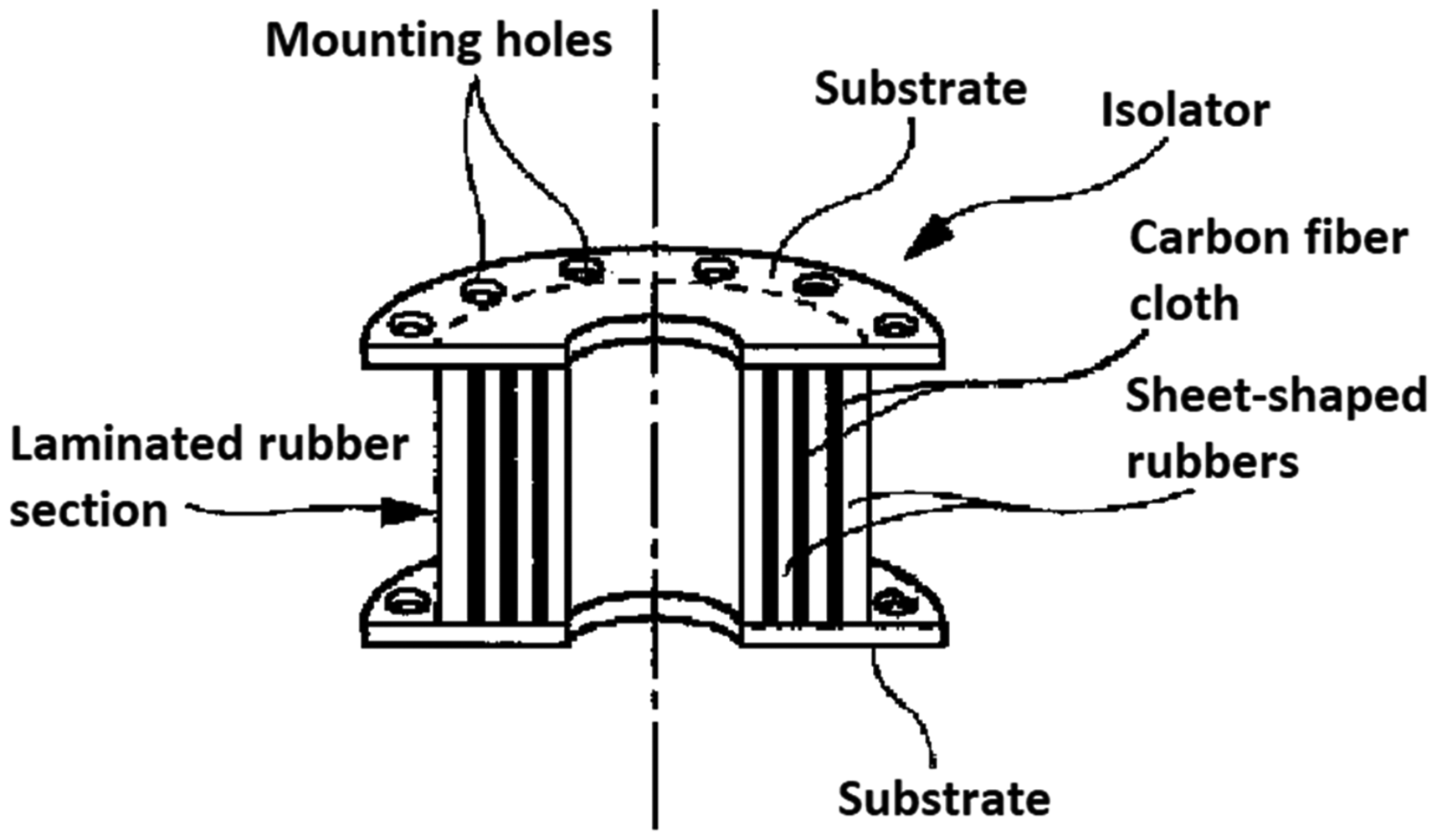
Schematic of a laminated rubber isolator.
One of the common seismic applications of NR is the use of cylinder rubber buffer devices to mitigate the lateral displacement of bridge superstructures.9,10 As illustrated in Figure 2, these buffers are installed between the superstructure and the substructure in the lateral direction to limit the relative lateral displacement between the super and substructure and to compensate for the relatively low horizontal stiffness of rubber-based bearings, which could lead to large horizontal deformations. 11 The deformation capacity and the axial stiffness of these rubber buffers should be effectively adjustable to meet different deformation and force demands. Moreover, very often the axial deformation and the load-carrying capacity of pure cylinder rubber buffers cannot meet the large deformation and force demands caused by strong earthquakes.
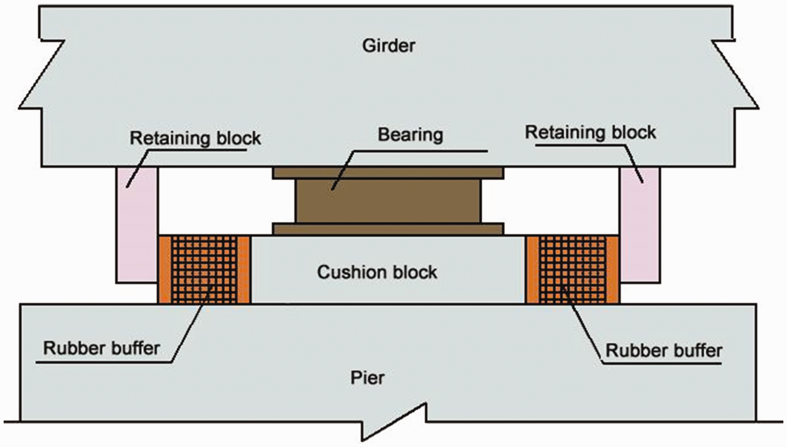
Schematic of typical rubber buffers system installed between bridge’s girder and pier.
This paper first presents a new rubber-based buffer with enhanced deformation and force capacity. The new buffer consists of cylindrical rubber wrapped (confined) with FRP composite. The lateral confinement provided by FRP helps reduce the lateral deformation of rubber which in turn enhances its compression stiffness. The main advantage of the new buffer is the ease of controlling its axial stiffness and deformation through adjusting the FRP wrapping scheme and thickness. Moreover, the new buffer is cheap and easy to maintain and install in practical engineering. The further research will focus on a similar buffer using high damping cylindrical rubber wrapped with high energy dissipation material such as shaped memory alloy wires to form a new energy dissipation device. The study result can be used in the seismic design of civil engineering. In order to verify the effectiveness of the axial stiffness adjustment method by wrapping a cylindrical rubber with high-strength materials, in this paper, the static mechanical behavior of this new FRP confined rubber buffer is investigated theoretically, numerically, and experimentally.
Constitutive relationship of pure NR
The phenomenological constitutive theory of rubber is widely applied in engineering using either the N-order polynomial model or the Ogden model. 12 The N-order polynomial model, the more popular among the two models, can be adapted to small, medium, or large strains by changing the orders and coefficients of the polynomial. The Ogden model, on the other hand, is usually applied for simulating large strains that can reach up to 700% strain. This model is characterized with higher order parameters and it requires a large number of experimental data to calibrate. Therefore, in this study, the N-order polynomial model which is more suitable for small and medium strains is utilized.
There are three common types of the N-order polynomial model, namely Neo-Hookean model, Mooney–Rivlin model, and Yeoh model.
13
The strain energy density function of these three models can be represented as follows
12


In addition, the stress–strain relationships of the three models can be given as follows
12


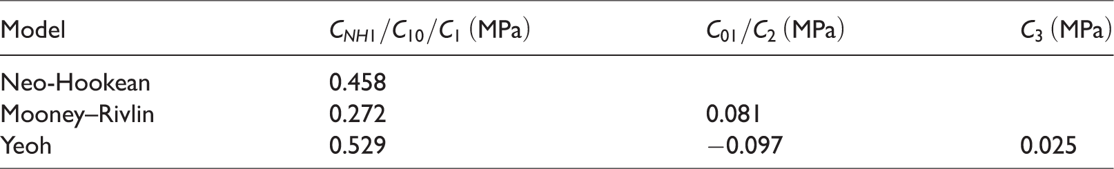
Since the constitutive relationship of NR is greatly dependent on the kind of rubber material, a uniaxial test was conducted to examine the stress–strain relationship of the test cylindrical rubber used in this study. Since there was no standard about the tested rubber buffer specimen in China, the dimension of the specimens depended on the laboratory test condition including the loading capacity of the tested machine and the specimen’s cost of production and transportation. The tested machine was an electrohydraulic servo universal testing machine with the maximal loading being 1000 kN. The specimens were produced by Hengshui Zhongtiejian Engineering Rubber LLC, China. The tested rubber cylinders were 200 mm in diameter and 200 mm in height. Their hardness was 60 HA. Thick steel plates and smooth Perspex plates were placed on both upper and lower surfaces of the tested specimens as shown in Figure 3 to ensure that the axial load is evenly distributed. A small amount of grease was applied on the interface between the Perspex plates and specimen to reduce the horizontal friction. The test results were used to compute the parameters associated with the three constitutive models previously presented in equations (1) to (3). The obtained parameters, which were the average value of three specimens (see Table 1), were used in calibrating the three models. Figure 4 presents comparison between the experimental and the experimentally calibrated stress–strain curves.
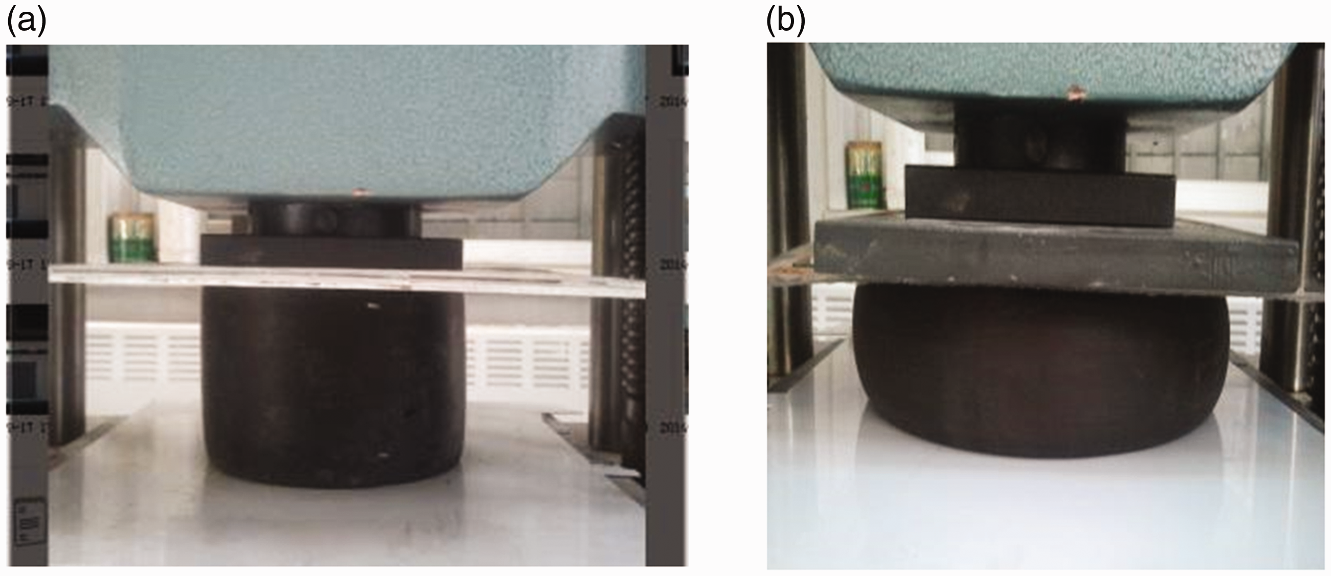
Static loading test of rubber. (a) Before testing and (b) during testing.
Model parameters of the three models.
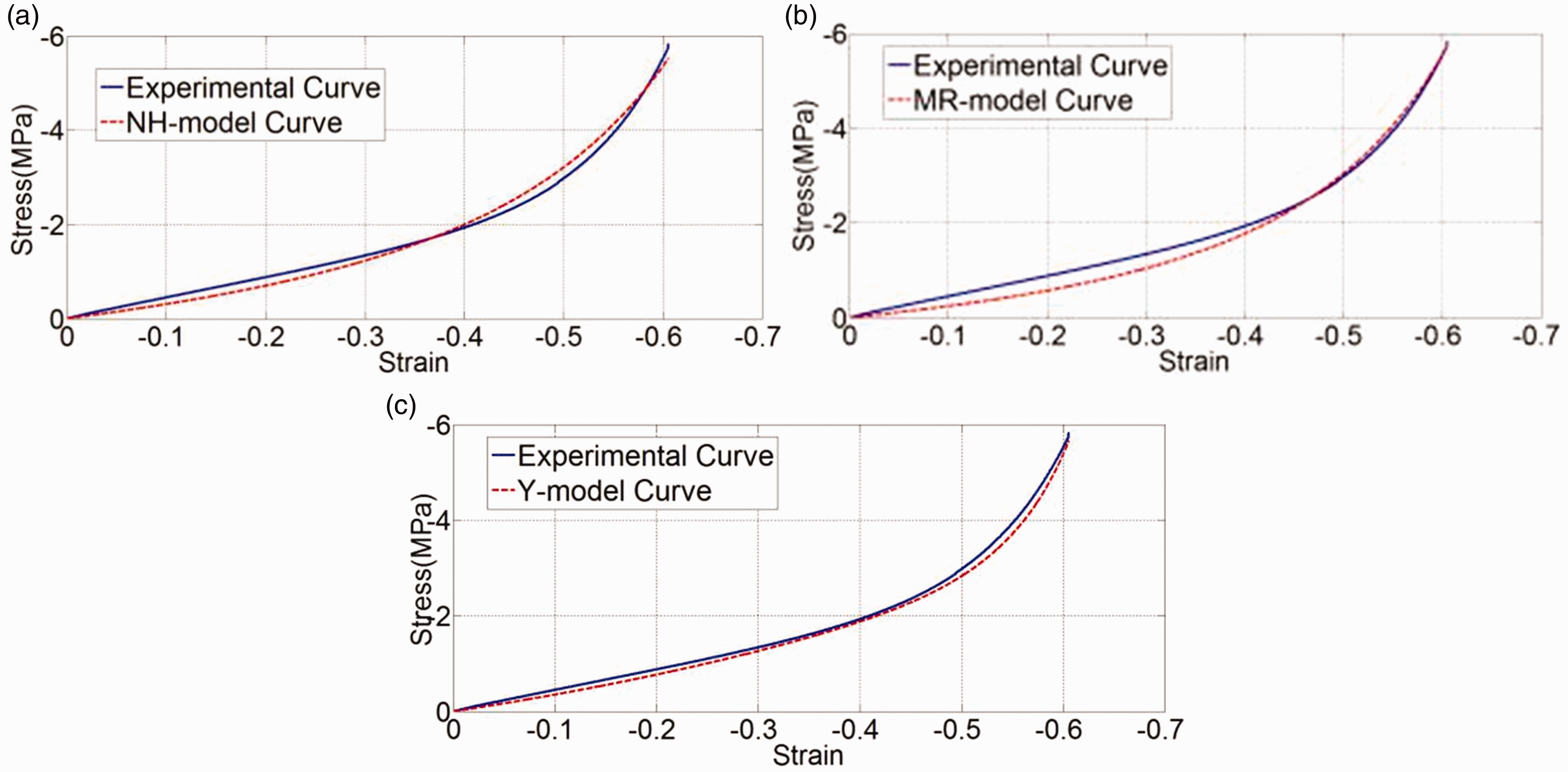
Comparison of the experimental and the experimentally calibrated stress–strain curves for the three models. (a) NH model, (b) MR model, and (c) Y model. MR: Mooney–Rivlin; NH: Neo-Hookean; Y: Yeoh.
As depicted in Figure 4 the rubber behaves linearly with a relatively low elastic modulus value of 4.25 MPa up until strain of approximately 0.4. When the strain exceeds 0.5, significant strain hardening is observed causing the elastic modulus to increase exponentially. Based on the comparison results shown in Figure 4, it was decided that the Yeoh model, which exhibited the most agreement with the experimental results is the most suitable among all three models to simulate the behavior of the rubber used in this study under compression.
Experimental testing of cylindrical rubber wrapped with FRP
Test matrix
The uniaxial compressive behavior of cylindrical rubber wrapped with FRP was examined experimentally. A total of 36 specimens (200 mm (diameter) × 200 mm (height)) were included in the test program. Each type of specimen included three specimens. A test setup similar to that was described earlier for pure rubber tests was utilized in testing these specimens (see Figure 5). The thickness of the FSs was 0.167 mm. They were produced by Shandong Jiangshan Fiber Technology Limited Company, China and their material property parameters were provided from the company. Strain gauges were attached to the surface of the FRP to measure the hoop strain of FRP.
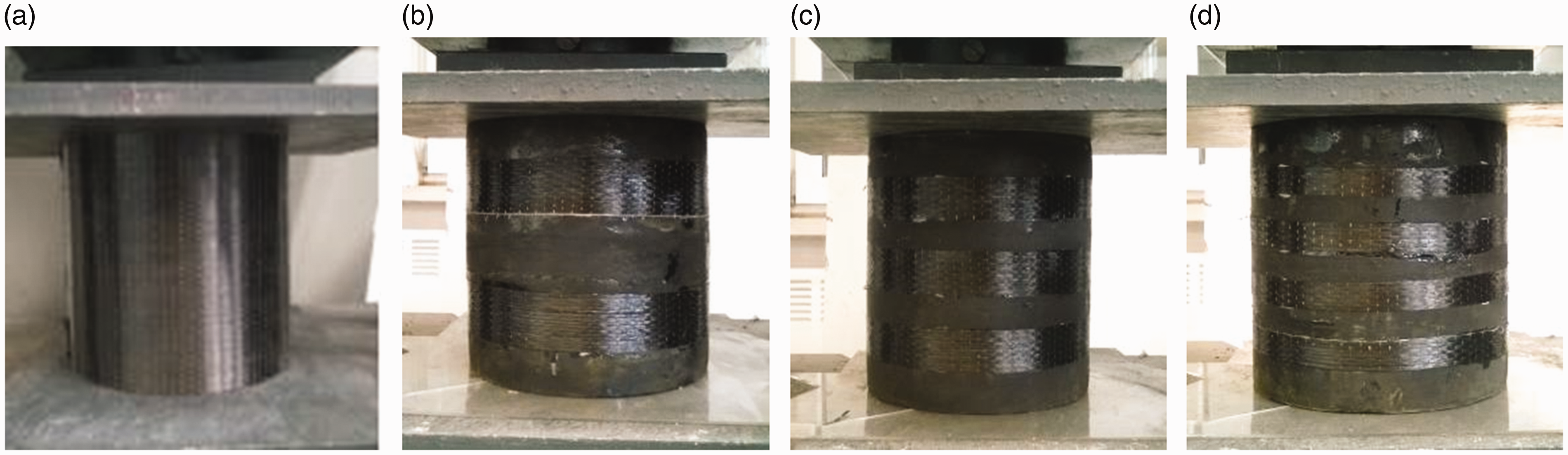
Specimens used for experimental testing using four different wrapping schemes. (a) All around, (b) two segments, (c) three segments, and (d) four segments.
Table 2 presents the specifications of each type of the 12 specimens. As shown in the table the specimens were classified into different wrapping schemes, widths, and number of layers (thickness). To examine the impact of applying carbon FRP composite wraps versus applying dry carbon FSs without impregnating it with resin, half of the specimens were wrapped with FS while the other half was wrapped with FRP (see Table 2). In preparing FS wrapped specimens epoxy resin was only applied at the overlapped region of the FSs as illustrated in Figure 6(a). The remaining portion of the wrap was not impregnated with resin but kept dry. However, for FRP wrapped specimens epoxy resin was applied throughout the entire area of the FSs using the traditional hand layup method (see Figure 6(b)). The length of the overlapping FS and FRP was 10 cm.
Test matrix of experimental specimens.
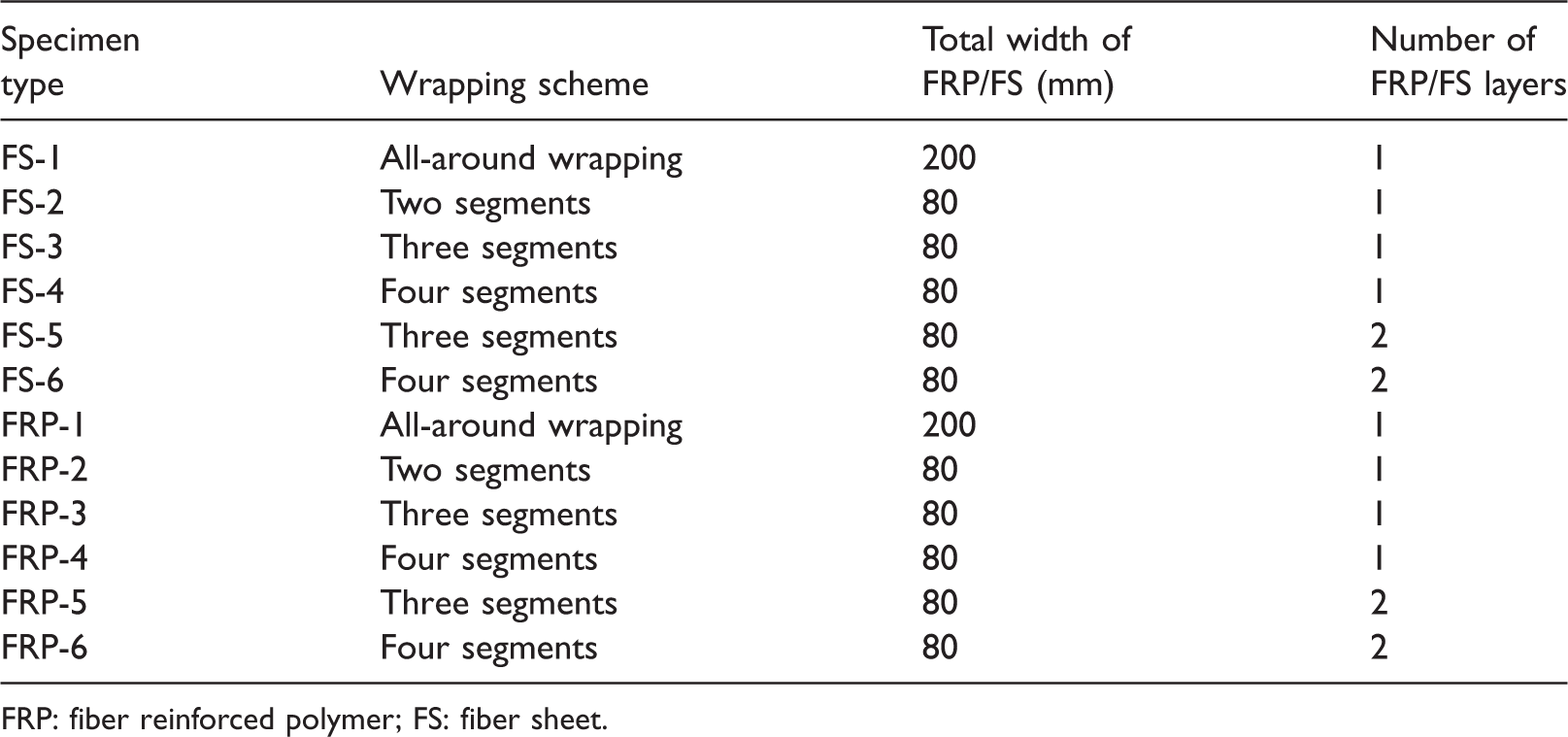
FRP: fiber reinforced polymer; FS: fiber sheet.
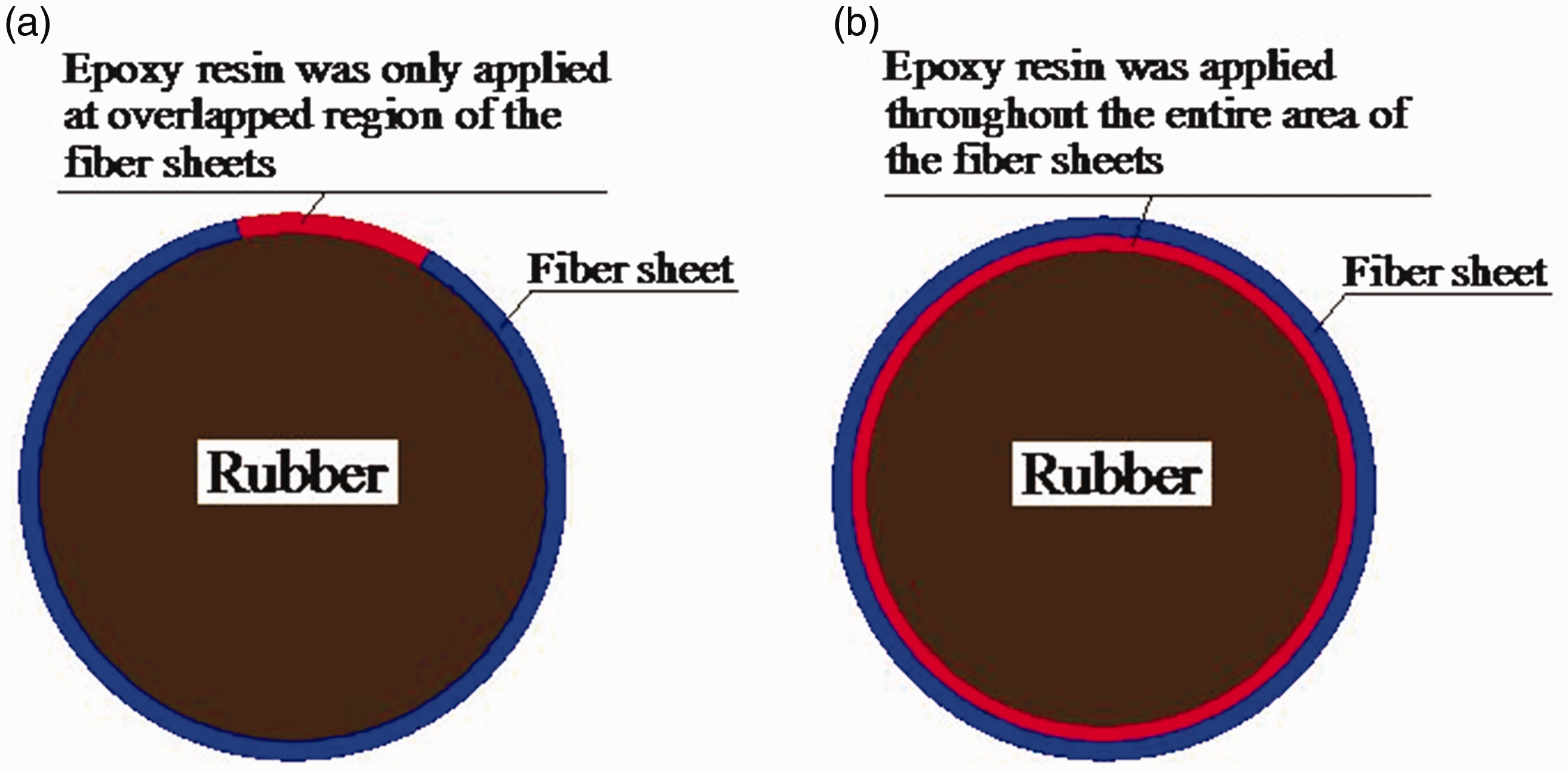
Cross section of the rubber wrapped with FSs and FRP composite. (a) FS and (b) FRP.
Test results
FS versus FRP results
Stress–strain curves of FS and FRP wrapped specimens are compared in Figure 7 along with that of pure rubber. Further, to provide a sample of the type of damages observed during testing and to be able to contrast the damage patterns of both FS and FRP wrapped specimens, Figures 8 and 9 present pictures depicting the progression of damage sustained during testing by specimens FS-6 and FRP-6, respectively. It can be seen from Figure 7 that both FS and FRP wrapped specimens exhibited significantly higher stiffness than the pure rubber specimen. Compared with the pure cylindrical rubber, the uniaxial stiffness of both FS and FRP all-around wrapped specimens was greatly improved by about 30 times. Moreover, the strength and the uniaxial stiffness of the all-around wrapping specimens were significantly greater than that of the piecewise wrapping specimens. As the load increased, before the rupture of the first FS or FRP strip the whole buffer remained in the elastic range. However, the maximum stress and the elastic modulus of FRP wrapped specimen were generally higher than that of FS wrapped specimen. There are several obvious sudden drop of stress in the figure depending on the number of the FS or FRP segments. Each sudden drop corresponded to a rupture of a FS or FRP strip. It was observed that there were some fluctuations in stress near the sudden drop, which was mainly caused by the successive fracture of fibers. The edge of the FS began to fracture first when the hoop strain of FRP was about 0.003 and all the fibers fractured when the hoop strain reached about 0.006. However, it is important to use caution when analyzing the results of specimens FS-1 and FRP-1 with all-around wrapping. The premature sudden drop in the stress in these specimens is attributed to the direct bearing of the loading plates on the FS and FRP wraps, which caused the wraps to wrinkle and fracture prematurely. This issue caused the axial deformation capacity of specimens FS-1 and FRP-1 to be limited compared to other specimens.
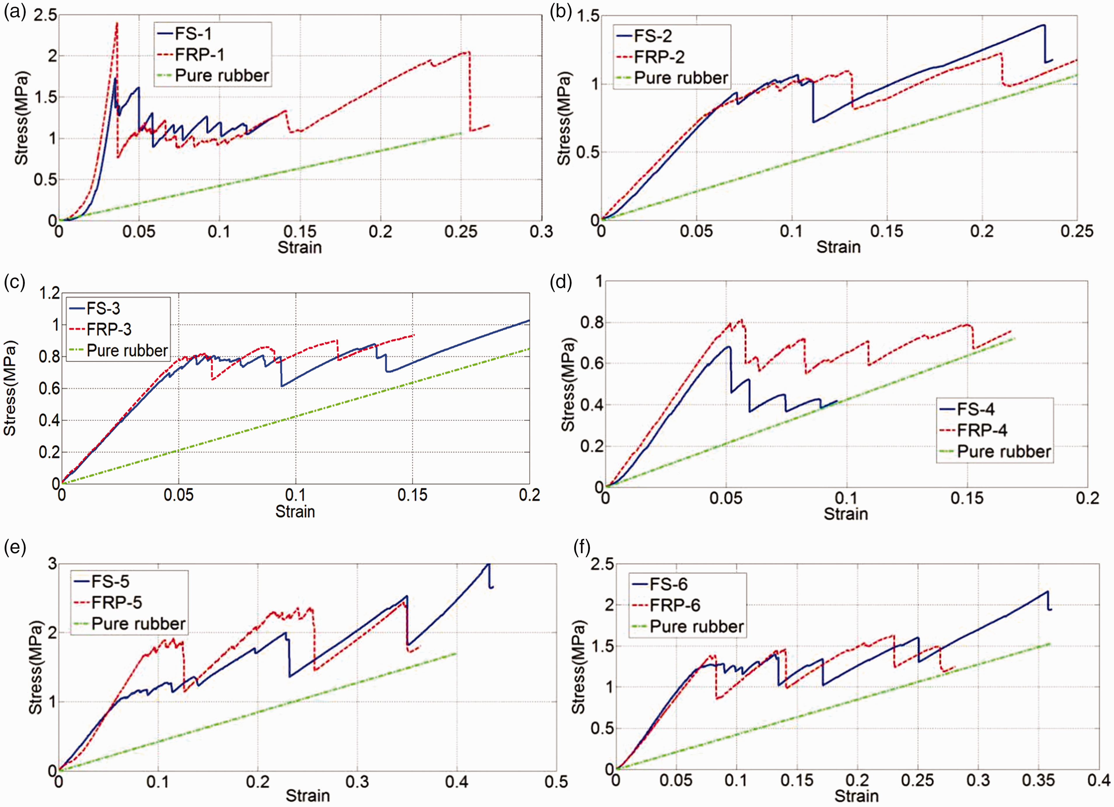
Comparison of the stress–strain curves of FS and FRP wrapped specimens. (a) FS-1/FRP-1, (b) FS-2/FRP-2, (c) FS-3/FRP-3, (d) FS-4/FRP-4, (e) FS-5/FRP-5, and (f) FS-6/FRP-6. FRP: fiber reinforced polymer; FS: fiber sheet.
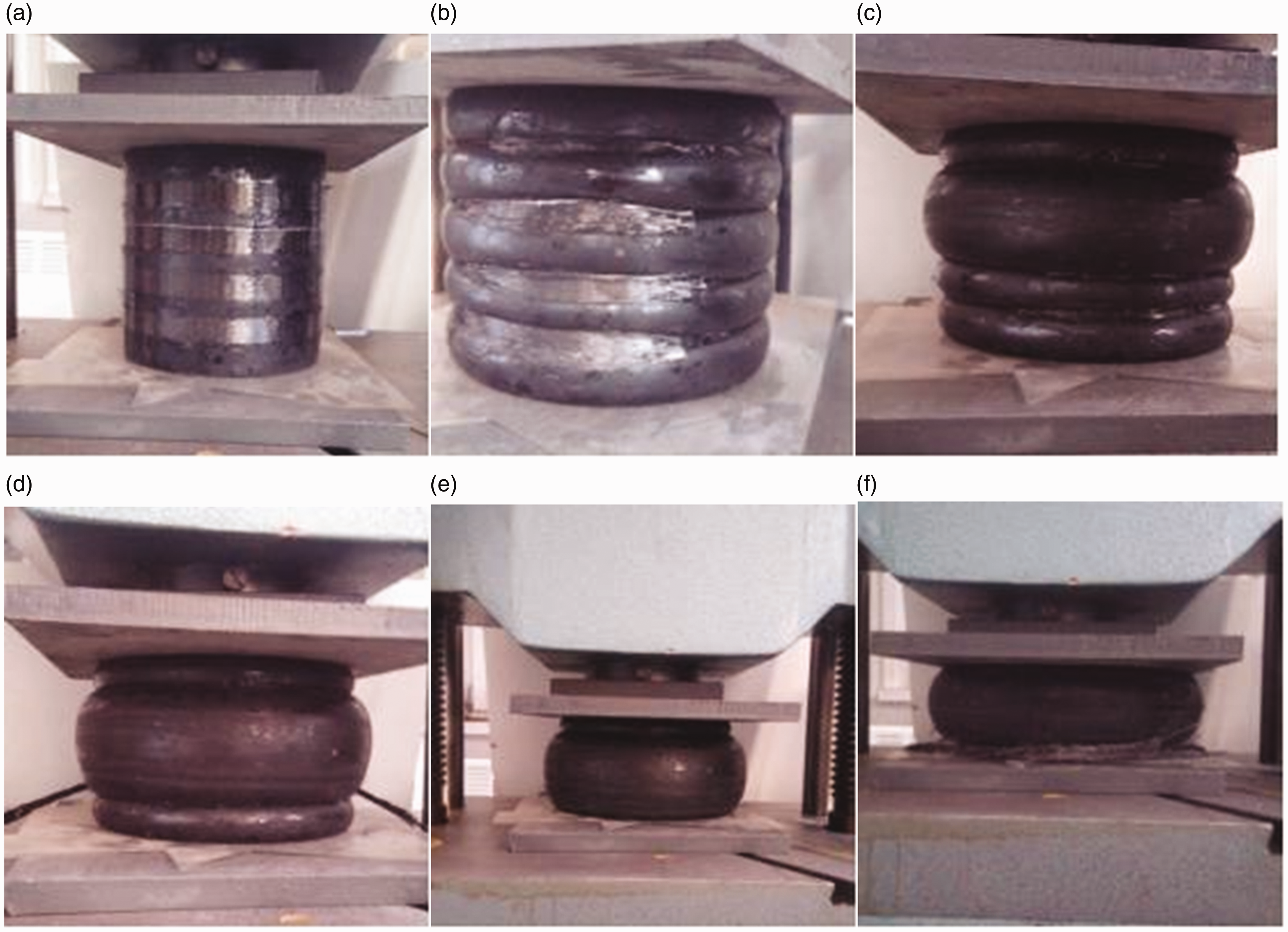
Testing process of specimen FS-6. (a) Before loading, (b) before the first fracture of FS, (c) first FS fracture, (d) second FS fracture, (e) third FS fracture, and (f) fourth FS fracture.
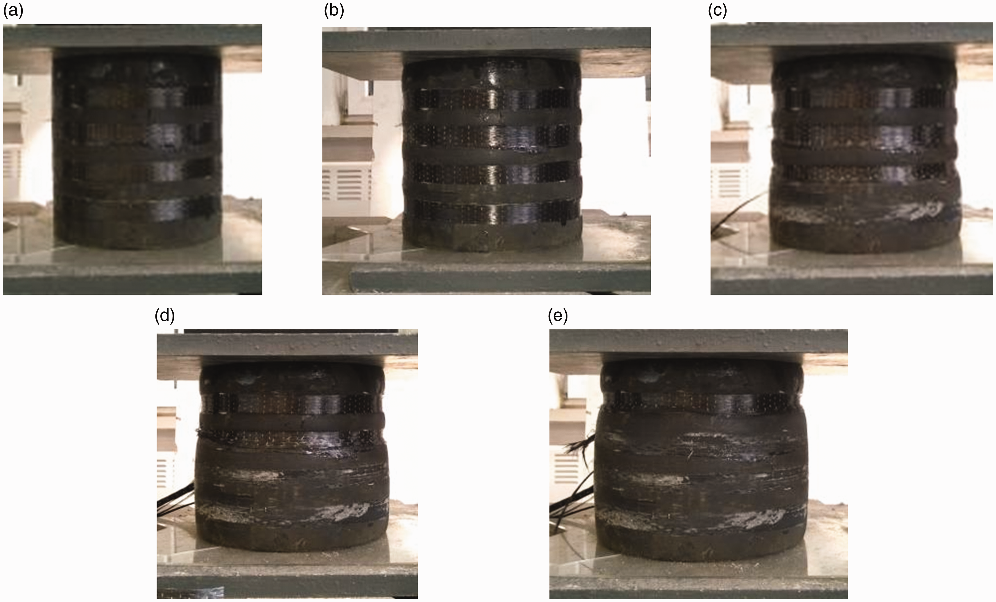
Testing process of specimen FRP-6. (a) Before loading, (b) before the first fracture of FRP, (c) first FRP fracture, (d) second FRP fracture, and (e) third FRP fracture.
Looking closely at the stress–strain results presented in Figure 7(f) for the two specimens FS-6 and FRP-6, which their damage progression is depicted in Figures 8 and 9, respectively, one can see that for the FS wrapped specimen, as load kept increasing, the original elastic modulus of the buffer was equal to 20.5 MPa and the value was five times that of the pure rubber. One FS strip at the middle of the height of the buffer ruptured first (see Figure 8(c)) followed by a sudden drop of stress. Then, the stress kept increasing linearly with a reduced modulus equal to about 53% of the original elastic modulus. The stress then kept increasing linearly after the second and the third stress drop, but the modulus of each stage was gradually decreasing.
As shown in Figure 7(f), the stress–strain curve of the FRP wrapped specimen was similar to that of the FS wrapped specimen. However, compared with the FS wrapped specimen, the stress drop of the FRP wrapped specimen was more obvious. This was attributed to the strong bond strength of the epoxy resin between the rubber and the FS. Since the FRP strip contributed more confinement to the rubber, it released more deformation and stress when it was fractured.
From Figures 8 and 9 it can be seen that as the load increased, the unconfined regions between the FS or FRP strips started to dilate (see Figures 8(b) and 9(b)). Initially, the bulging level of each part of the unconfined rubber between the FS or FRP strips was similar. After the fracture of the first FS or FRP strip, the length of the unconfined rubber increased so the rubber sustained significant bulging between the other two FS or FRP strips until the fracture of the second strip. After the second strip rupture, as shown in Figures 8(d) and 9(d), the maximum bulging occurred in the middle height of the unconfined rubber. Finally, the remaining FS or FRP strips fractured sequentially as the load continued increasing. However, from the comparison of Figures 8(b) and 9(b) one can see that the bulging level of the FRP wrapped specimen was quite less than that of the FS wrapped specimen. This was attributed to the effect of epoxy in the FRP wrapped specimens, which provided bond between the wraps and the rubber, which helped prevent the wrinkling of the wraps under loading as was observed in the FS wrapped specimens.
Effect of wrapping schemes
This section focuses on evaluating the impact of wrapping schemes on the uniaxial stiffness and strength which are considered the most critical design parameters for the new buffer. Throughout the rest of the paper the term strength will be used to refer to the maximum stress at the onset of fiber fracture. Figure 10 presents stress–strain behaviors for specimens with different wrapping schemes up until the point of first fiber fracture and the uniaxial stiffness of partial specimens are shown in Table 3. The data discussed in the following figures and tables are the average values of each group of specimens.
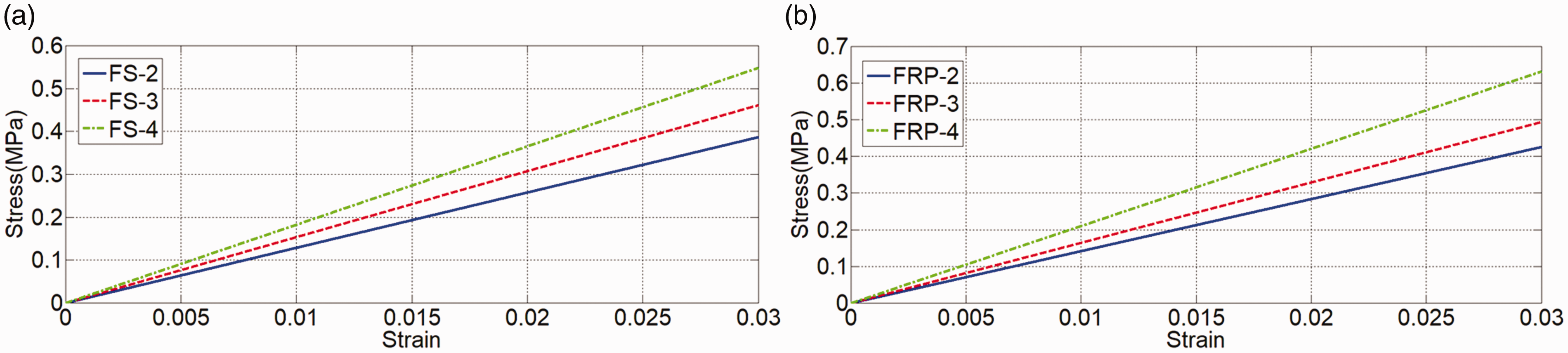
Comparison of the behaviors of the FS-wrapped (a) and FRP-wrapped (b) buffer using different wrapping schemes. (a) FS and (b) FRP. FRP: fiber reinforced polymer; FS: fiber sheet.
Axial stiffness of partial specimens.
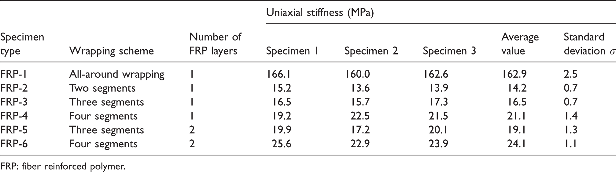
FRP: fiber reinforced polymer.
From the comparison of the behaviors of specimens FS-2, FS-3, and FS-4 and specimens FRP-2, FRP-3, and FRP-4 (see Figure 10(a) and (b) and Table 3) it was noted that although the total width of the strips was the same (80 mm) in all cases, the different spacing between each segment of the strips led to different uniaxial stiffness. Compared with FS-2 and FRP-2, the uniaxial stiffness of specimens FS-3 and FRP-3 was increased by about 19 and 16%. The uniaxial stiffness of specimens FS-4 and FRP-4 with less spacing between strips was increased by about 19 and 28% compared to that of specimens FS-3 and FRP-3, respectively. The results indicate that the uniaxial stiffness of the buffer increases as the number of segments increases with the same total width of FS strips. This result is due to the less bulging of the unconfined region of rubber with less spacing between strips.
Effect of FRP thickness
Another important factor that was studied is the wrap thickness which is represented by the number of FS or FRP layers. Through comparison between the behaviors of the specimens with one and two layers of FS or FRP (see Figure 11), it could be seen that regardless of the wrapping scheme (three- or four-segment wrapping), using two layers of FS or FRP increased the uniaxial stiffness of the buffer by about from 12 to 16% compared to the one layer cases. This relatively small increase in the buffer stiffness as a result of increasing the thickness of the wraps indicates that employing the wrapping scheme is a more efficient way to control the uniaxial stiffness of the buffer compared to changing the wrap thickness.
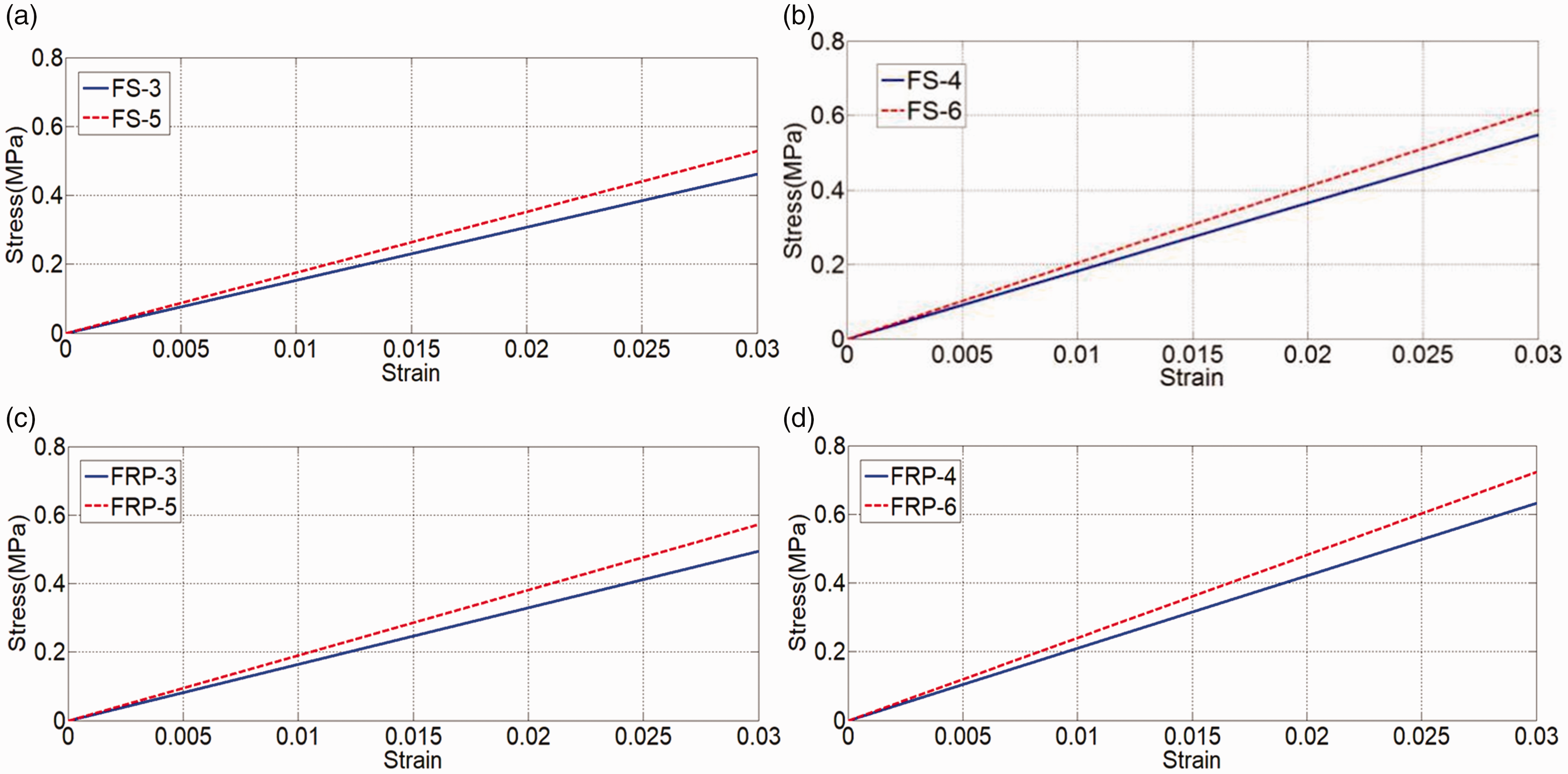
Comparison of the uniaxial stiffness under different number of FS or FRP layers. FRP: fiber reinforced polymer with impregnating it with resin; FS: fiber sheet without impregnating it with resin.
Theoretical behavior of rubber composite buffer wrapped with FRP
Different wrapping schemes of FRP can be applied to confine the lateral deformation of the cylindrical rubber including all-around wrapping, piecewise wrapping, and spiral wrapping. To simplify the theoretical derivation, this section focuses only on the all-around wrapping scheme. The derivation was based on the following two assumptions:
Strength and stiffness perpendicular to the FRP fibers are small and negligible, and Horizontal friction on the upper and lower compression planes of rubber is small and negligible. To simplify the derivation, the stress–strain curve of the Yeoh model is divided into three linear phases based on strain value:
First phase:
Second phase:
Final phase:
Due to the confinement of FRP, the strain of rubber is expected to be less than 0.4, hence, in this paper the emphasis was within the first phase.
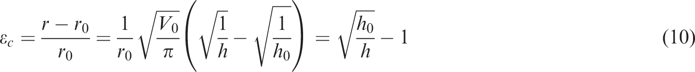
A schematic of a buffer with the all-around FRP is shown in Figure 12. The cylindrical rubber is wrapped by the all-around FRP in the circumferential direction. Figure 13 shows schematic of the buffer before and after deformation. The initial volume of the cylindrical rubber 
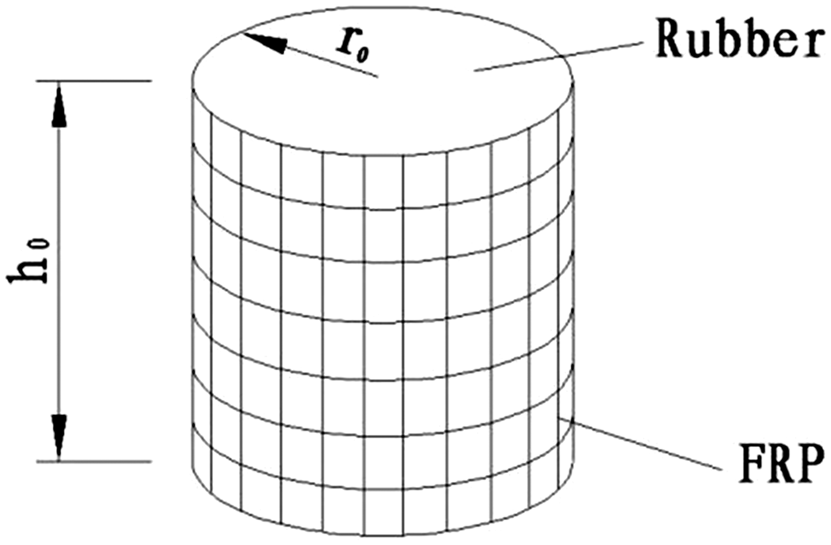
Cylindrical rubber wrapped all around by FRP. FRP: fiber reinforced polymer.
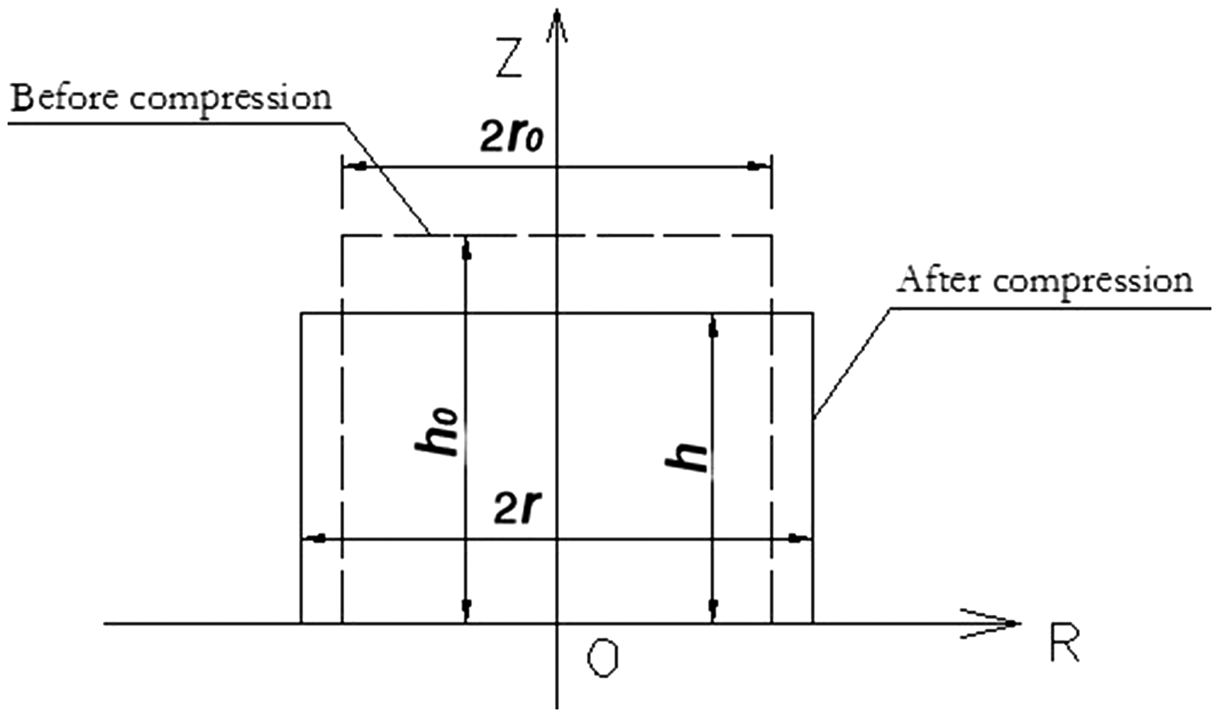
Schematic of the rubber before and after deformation.
According to the law of conservation of energy,
14
the equilibrium of the work done by the pressure and the sum of the strain energy of rubber and elastic energy of FRP can be expressed as

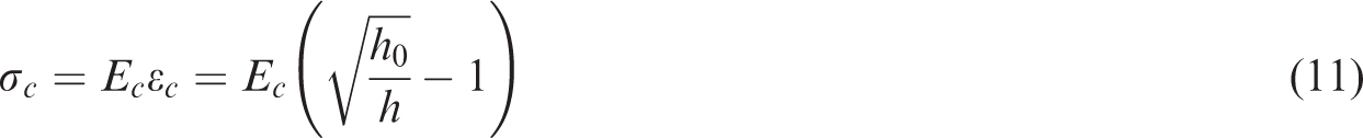
Since for simplicity the stress–stain relationship is assumed to be linear, equation (12) can be expressed in another form


From the above equations, the analytical uniaxial stiffness of the buffer is 210.1 MPa.
Numerical simulation of cylindrical rubber wrapped with FRP
In this section, finite element (FE) method is used to analyze the behavior of the proposed FRP wrapped buffer. All six FRP wrapped specimens presented in Table 2 (FRP-1 through FRP-6) were analyzed. The previously derived constitutive relationship using the Yeoh model coefficients was implemented into the FE software ANSYS considering hyperelasticity used in the analysis.15,16 For purpose of discussing the effect of the friction on the both ends of the rubber, two 5 cm thickness steel loading plates were simulated in the FE model as shown in Figure 14. In the FE model solid elements were used to simulate rubber and steel plates and FRP was simulated using shell elements. Surface-to-surface contact elements were modeled by the contact surfaces between steel loading plate and rubber. The interface of the rubber and FRP was simulated by node-coupling method in all directions. The Young’s modulus of FRP was taken as 240 GPa in the model. Only the elastic stage was considered and the analysis was stopped when the first FRP strip was ruptured. Axial forced displacement was applied to the upper loading plate and the axial stiffness of the buffer can be achieved.
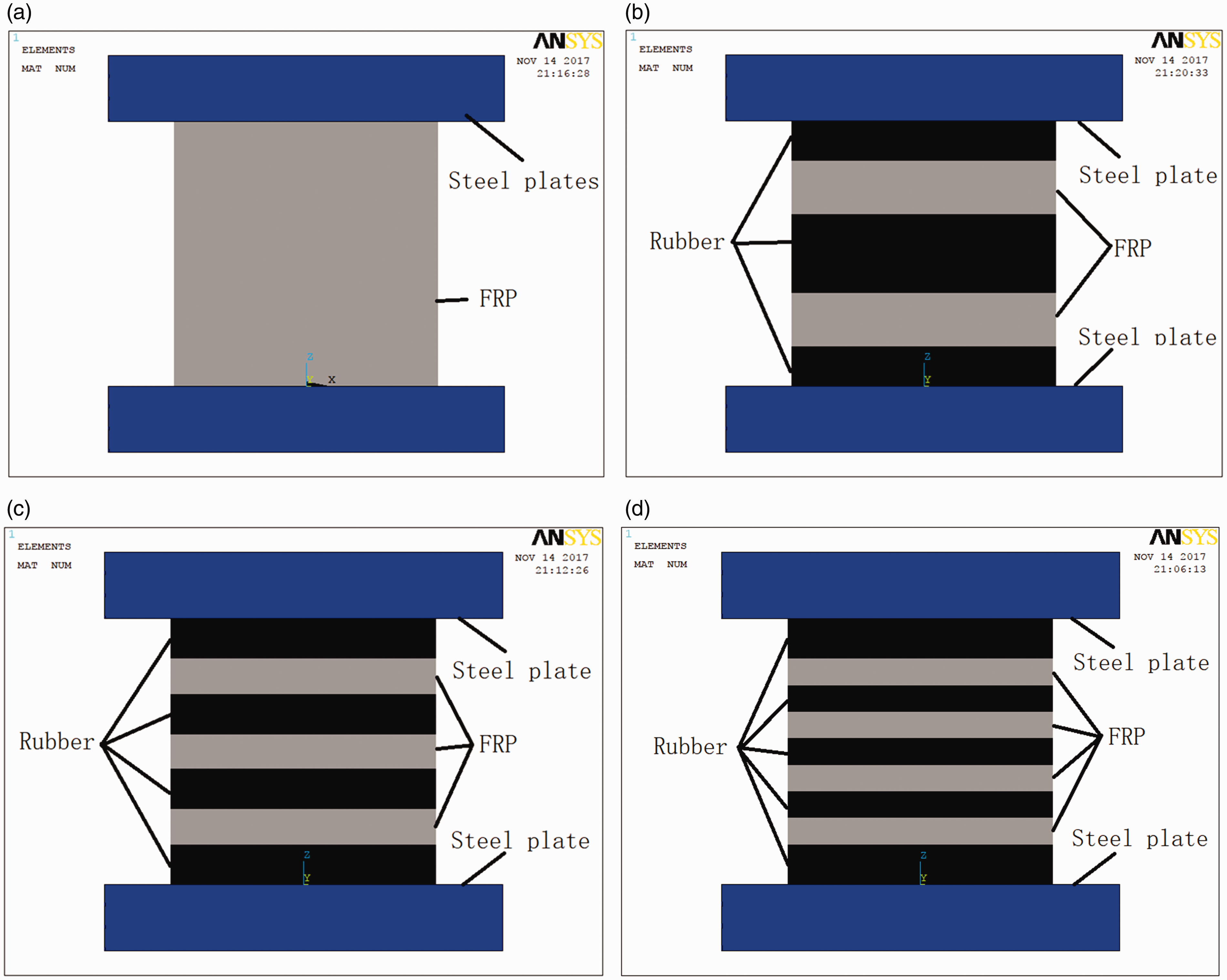
FE models of the buffer. (a) All around, (b) two segments, (c) three segments, and (d) four segments. FRP: fiber reinforced polymer.
In order to choose the suitable mesh density, different mesh sizes including 10, 5, 2.5, and 1 mm were applied to the analysis of the two-segment-one-layer case and the four-segment-one-layer case. The FE analysis result was shown in Figure 15. From the figure it can be seen that with the decrease of the mesh size, the uniaxial stiffness of the buffer was reduced. After the mesh size reached 2.5 mm the axial stiffness value tended to stability. The axial stiffness values calculated using 2.5 and 1.0 mm mesh size was less than 1% difference. Hence, 1 mm mesh size element was used in all the above models. Since the mesh photo with high density elements was not clear, the mesh detail did not display in Figure 14.
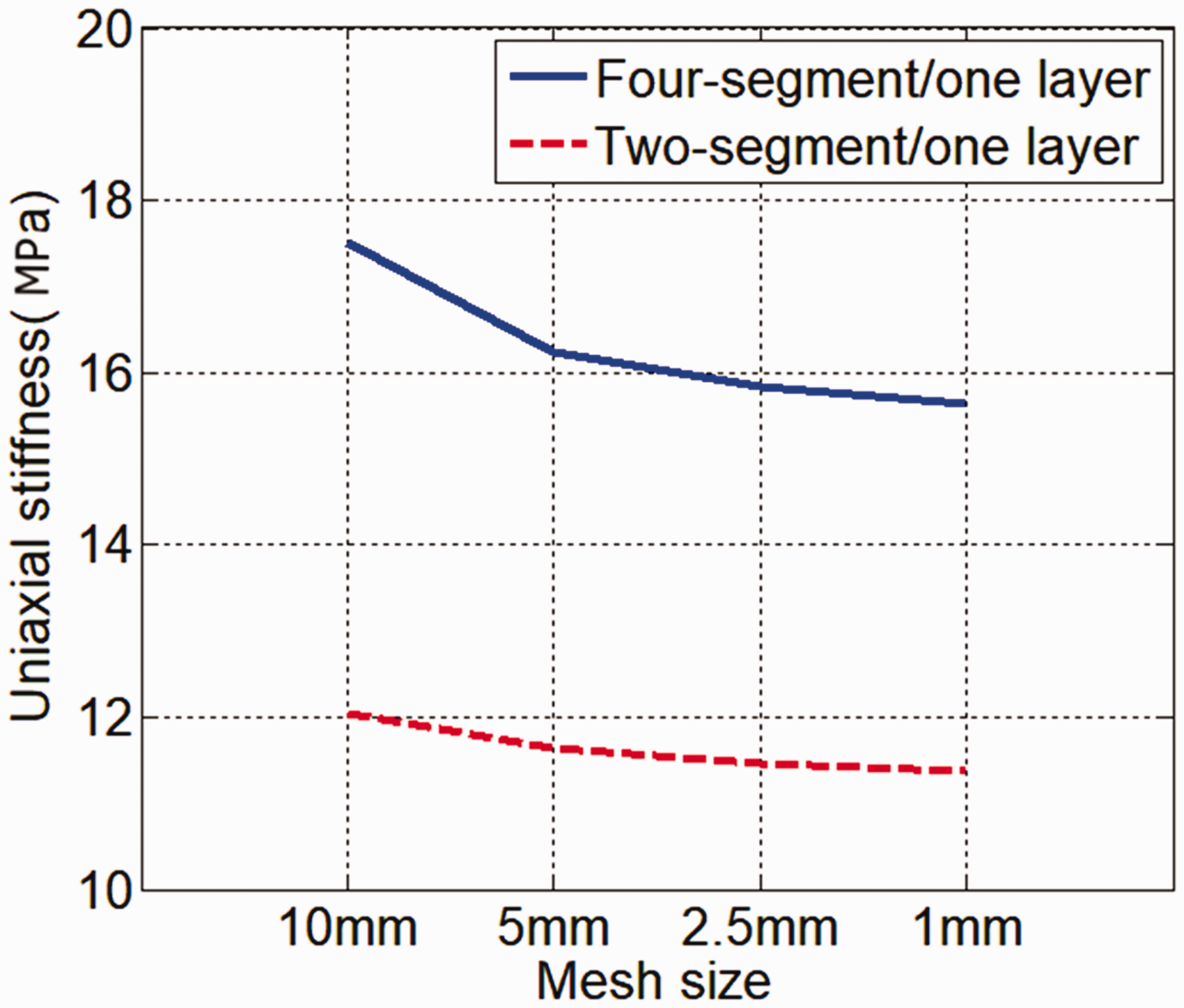
Uniaxial stiffness under different mesh sizes.
A comparison between FE and experiment results was conducted for the six cases described earlier. The FE results considering friction coefficients (
Uniaxial stiffness of experimental and FE results.
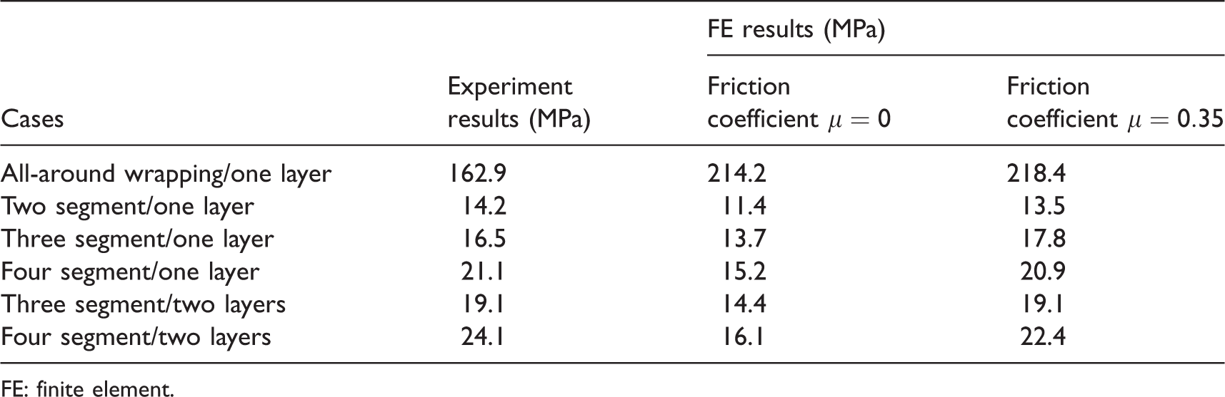
FE: finite element.
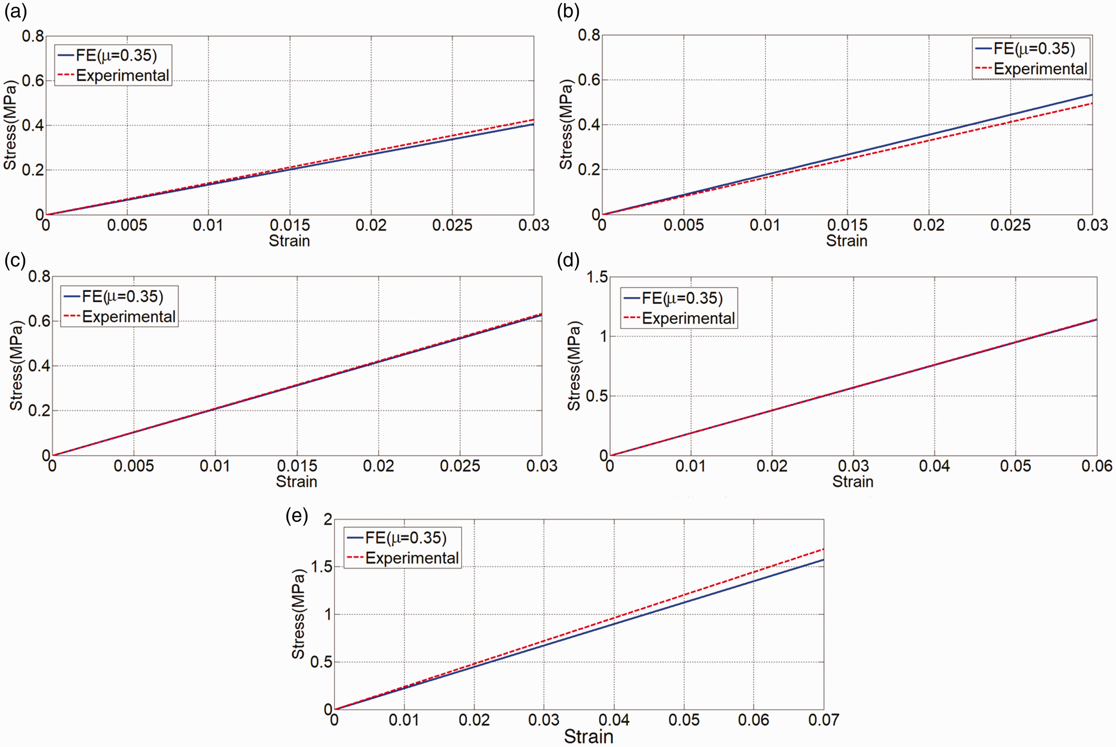
Comparison between FE and experiment results. (a) Two segment/one layer, (b) three segment/one layer, (c) four segment/one layer, and (d) three segment/two layers, and (e) four segment/two layers. FE: finite element.
As for the all-around specimens, the comparison among analytical, FE (
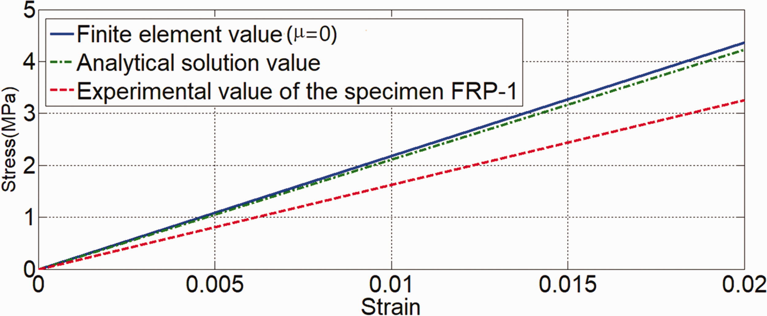
Comparison among analytical, FE, and experimental results of all-around specimens. FRP: fiber reinforced polymer.
Conclusions
This study focused on exploring the behavior of a new structural buffer which consists of cylinder rubber wrapped with FRP. Through theoretical derivation, numerical simulation, and experiment methods, the static mechanical performance of the new buffer was assessed and the following conclusions can be drawn:
Through theoretical analysis and experimental testing it was shown that among the three commonly used N-order polynomial constitutive models (Neo-Hookean model, Mooney–Rivlin model, and Yeoh model), the Yeoh model was the most suitable that could be utilized to describe the stress–strain behavior of rubber under uniaxial compression. Both FS and FRP wrapped specimens exhibited significantly higher stiffness than pure rubber specimen. However, the elastic modulus and the strength of FRP wrapped specimens were generally higher than that of FS wrapped specimens. The strength and the uniaxial stiffness of the all-around wrapping specimens were significantly greater than that of the piecewise wrapping specimens. Providing more uniform wrapping scheme by increasing the number of wrapping strips while maintaining the total width of strips was found to have significant effect on improving the uniaxial stiffness of buffer. With the same total width of wrapping FS/FRP, the uniaxial stiffness of specimens increases as the number of wrapping strips increases. Increasing the thickness of FRP sheets could also serve to enhance the uniaxial stiffness. However, it has much less impact on enhancing the stiffness compared to the wrapping scheme. Comparing the numerical and experimental results showed the effectiveness of FE method in predicting the uniaxial compressive behavior of the proposed buffer. Though the strength and the uniaxial stiffness of the all-around wrapping specimens were significantly increased, considering its manufacture difficulty and low deformability, this wrapping scheme is not suitable for practical engineering.
In general, the results of this study indicate that the uniaxial stiffness of a cylindrical rubber can be adjusted effectively by different wrapping scheme of confined materials such as FRP or FS. This study was limited by the absence of the theoretical derivation of the piecewise wrapping and spiral wrapping scheme. Further studies need to be carried out in order to develop this type of buffer to a new energy dissipation device which consists of a high damping cylindrical rubber wrapped with high energy dissipation material such as shaped memory alloy wires.
Footnotes
Declaration of conflicting interests
The author(s) declared no potential conflicts of interest with respect to the research, authorship, and/or publication of this article.
Funding
The author(s) disclosed receipt of the following financial support for the research, authorship, and/or publication of this article: The authors acknowledge the support from China Scholarship Council and National Natural Science Foundation of China under Award No. 51678110 and No. 51108058.