
Abstract
The paper presents an analysis of vehicle vibration, ride comfort and handling which have a decisive influence on health and safety of a driver. Experiments were carried out for a commercially available experimental all-terrain vehicle in the field in hard conditions with retaining the sufficient repeatability. The vehicle is equipped with a complex vibration control system, taking advantage of four automotive magnetorheological dampers. Numerous sensors, which measure acceleration in four points of the vehicle body, near the driver’s seat, feet and hands, body orientation in space and speed of vehicle wheels, are available in the vehicle. They were used for evaluation of magnetorheological dampers’ control signals and analysis of vibration affecting the driver. Constant values of magnetorheological damper control current were used for emulation of different settings of passive suspension. The analysis performed in frequency domain showed how vibration propagates in a medium-sized all-terrain vehicle and indicated that driver’s hands are mostly affected by the road-induced vibration. It was also confirmed that the greatest improvement of ride comfort can be obtained for the soft suspension, i.e. uncontrolled magnetorheological dampers. Furthermore, the Skyhook algorithm was implemented, including the proportional control of the magnetorheological damper force and the inverse Tanh model of the magnetorheological damper. It was validated for the wideband road-induced excitation contrary to the experiments commonly presented in the literature, which are performed only for harmonic excitation. It was shown that the properly tuned Skyhook algorithm enables improving vehicle handling compared to the passive suspension and simultaneously it can maintain the similar or even better results of ride comfort.
Keywords
Introduction
Vehicle driver and passenger bodies are particularly exposed to the negative effects of vibration in the forms of shocks induced by sudden road bumps and holes as well as continuous vibration caused by unevenness of the road profile. Smith et al. 1 indicated a correlation between the root mean square value of acceleration and general discomfort of the passengers. However, the effect of vibration depends strictly on its frequency. Vibrations are commonly analysed with respect to the resonance frequencies of the human body, e.g. 3 Hz corresponds to the upper limbs, 25 Hz corresponds to parts of head, as was listed by Cempel. 2 Dedicated biodynamic models can be used in order to analyse the influence of vibration on seated occupants. For instance, method of evaluation of four-degree-of-freedom biodynamic model using non-dominated sorting genetic algorithm II based on Pareto optimization principle was proposed by Bai et al. 3 In order to cover these resonance frequencies, the norms, e.g. BSI 4 or ISO 5 provides frequency weightings for analysis of vibration based on acceleration where vertical acceleration is commonly used. Els 6 presented results of comparison of objective methods for ride comfort and subjective comments of a crew driving different military vehicles in off-road conditions. They also stated that vertical direction of measurement was dominant while frequency weighting was not very important in their studies due to the frequency content of measured acceleration. Barone et al. 7 reported results of experiments carried out for five cars of different categories moving with different speeds and analysed ride comfort using frequency weightings. Furthermore, an analysis of exposure to vibration for a driver’s seat of an agricultural tractor was presented by Cvetanovic et al. 8
Vehicle handling is one of the criteria related to driving safety, which can be evaluated for steady-state or transient response of a vehicle as was summarized by Crolla et al. 9 The steady-state response is commonly tested for a vehicle moving with increasing speed along a constant radius circle. In the case of transient response, various driving test manoeuvres are used, e.g. J-turn or fish-hook. The vehicle handling can be evaluated using different quantities describing motion of a vehicle where the chance of a rollover is commonly analysed. Dahlberg 10 presented a method of determining dynamic rollover threshold which is based on roll angle measurements and includes information about the kinetic energy of the vehicle. Alternatively, Crolla et al. 9 and Uys et al. 11 took into account roll rate for analysis of the likelihood of rollover. Pitch angle was additionally recommended for analysis of ride performance by Choi et al. 12 for a road vehicle subjected to bump excitation and equipped with electrorheological dampers controlled by the Skyhook algorithm.
The influence of road-induced vibration on ride comfort and handling should be especially examined in the case of off-road vehicles which are widely used, e.g. by emergency services in order to get to hard-to-reach places or which are included in military equipment for transportation purposes. Since off-road vehicles exhibit high centre of gravity and greater suspension travel, they are especially prone to excessive pitching and rolling. Els et al. 13 showed based on simulations of three different vehicles that ride comfort and handling are contradictory, which is especially demanding for the designer of suspension systems. Settings of the vehicle suspension system should be selected in a way which allows for isolation of passengers from unevenness while simultaneously maintaining control over the vehicle as was stated by Els et al. 13 Uys et al. 14 proposed a method of determining the parameters of vehicle suspension taking into account weighted root mean square vertical acceleration of driver and passenger. Maciejewski et al. 15 presented methods for optimization of parameters of horizontal seat suspension and for improvement of dynamic seat comfort and the suspension travel by shaping the suspension’s vibro-isolation properties. However, especially demanding cases are those where ride comfort and handling are simultaneously required, e.g. in the case of double lane change manoeuvre performed on a Belgian paving. Combined analysis of both factors was presented by Holdmann and Holle 16 where the influence of suspension and tire parameters on both ride comfort and driving safety for different driving manoeuvres was studied for a vehicle model.
A desired vehicle suspension system should result in significant improvements in both ride comfort and vehicle handling. It is not feasible for classical passive suspension where a compromise needs to be found in the design stage of the vehicle. Such requirement needs adaptive suspension elements to be used, e.g. active force generators or semi-active magnetorheological (MR) dampers. Sibielak et al. 17 reported results of experiments performed for a quarter-car set-up with slow-active suspension elements. They analysed improvement of ride comfort, vehicle handling and road holding, and tried to simultaneously keep minimum power consumption. Ning et al. 18 presented a designed and fabricated active seat suspension which can be applied in heavy-duty vehicles. MR dampers are favoured over active elements for their low energy consumption, short response time to changes of control current, as reported by Koo et al. 19 and inherent stability. Sapiński 20 presented comprehensive studies on modelling and control methods dedicated to MR dampers. Bai et al. 21 reported an extended version of a semi-active seat suspension where both longitudinal and vertical vibration modes can be controlled by transformation into the rotary motion of an MR damper. Ahamed et al. 22 analysed performance of an MR damper with energy harvesting which is a significant improvement to standard MR dampers which are only dissipating energy of vibration.
Significant non-linearity revealed in the force–velocity characteristics of MR dampers, as reported by Sapiński, 20 requires sophisticated semi-active control schemes to be applied. Karnopp et al. 23 proposed the well-known Skyhook algorithm which is aimed at mitigation of the vehicle body vibration independently of the source of vibration. Thus, it not only improves ride comfort, but also influences vehicle handling by stabilizing the vehicle body motion. Alternative approaches to improvement of ride comfort were presented by Hong et al. 24 based on modified Skyhook control or by Kurczyk and Pawełczyk, 25 where a fuzzy control algorithm was applied for improving ride comfort of a vehicle model. Some researchers proposed improving control of the vehicle suspension using additional optical sensors, e.g. vision cameras are used in Yankun et al. 26 or laser range scanners in Budzan and Kasprzyk. 27 However, the typical Skyhook algorithm is favoured for its robustness and reliability.
Many of the listed articles present studies of ride comfort and vehicle handling carried out based on computer simulation. Experiments carried out in terrain exhibit incomparably more difficult conditions. The majority of presented experimental results related to the whole body vibration is limited to evaluation of the root mean square values, not taking into account the frequency content of measured signals. Very often they also relate to the typical commercial road vehicle not considering specific features of off-road vehicles. Contrary to commercial vehicles, a driver of the off-road vehicle is not covered by a cabin from unfavourable conditions and is especially subjected to vibration and shocks during an extensively long drive. Therefore, these vehicles should be examined enough with respect to optimization of suspension parameters and adaptive suspension systems. However, this problem is rarely dealt with. Moreover, limited size of quads makes it difficult to apply high-power-consuming suspension elements and controllers.
This paper relates to an experimental analysis of vibration influencing the driver of a real-size, commercially available all-terrain vehicle (ATV) which is described in detail in the ‘Experimental set-up’ section. Original shock absorbers of the vehicle were replaced with four MR dampers. The suspension is controlled by a complex control system which is dedicated to the improvement of ride comfort and driving safety. Several accelerometers installed in the vehicle show how vibration propagates in the vehicle and which parts of the driver’s body are mostly affected. Application of MR dampers allows for emulation of a passive suspension with different damping in the same vehicle, which was presented in the ‘Analysis of vibration affecting the driver’ section.
The Skyhook algorithm was implemented in the controller in the form described in the ‘Vibration control using MR dampers’ section, including additional signal processing routines. Its performance was compared to the passive suspension in the ‘Results of ride comfort and vehicle handling’ section. The analysis was performed based on ride comfort and vehicle handling quality indices and also in the frequency domain based on PSD characteristics. The experiments were carried out for the vehicle riding in hard ambient conditions in low temperature for different speeds in the field. Thus, algorithm performance was tested for a wideband road-induced excitation which is an advantage of the presented analysis, since mechanical systems are very often examined in the literature only for harmonic excitations. The results are discussed at the end of the manuscript and concluded in the ‘Conclusions’ section.
Experimental set-up
Tests were performed for a modified ATV of type CF-Moto-500 (presented in Figure 1). Main technical data of the vehicle are listed in Table 1. Replacement of standard shock absorbers with MR dampers produced by the Lord Corporation was the key modification of the vehicle allowing for control of its suspension parameters. The MR dampers are controlled by a dedicated main controller located in the rear part of the vehicle body. The control system takes advantage of several sensors installed in the vehicle and tracking its motion, i.e. accelerometers, suspension deflection sensors and the IMU module. Furthermore, the vehicle speed can be measured using wheel speed sensors.
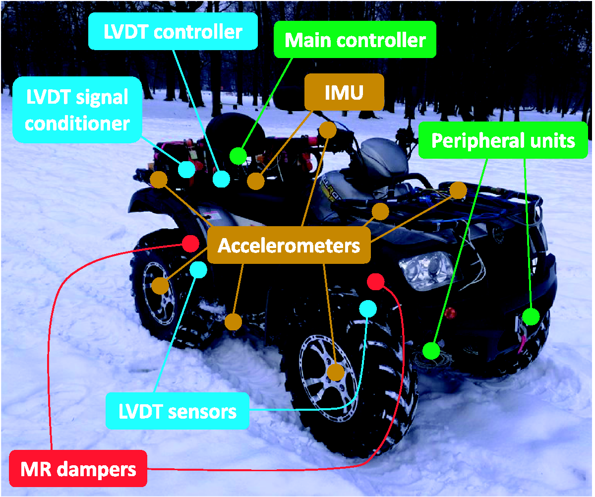
Experimental off-road vehicle with vibration control system. IMU: inertial measurement unit; LVDT: linear variable differential transformer; MR: magnetorheological.
Main technical data of experimental vehicle.
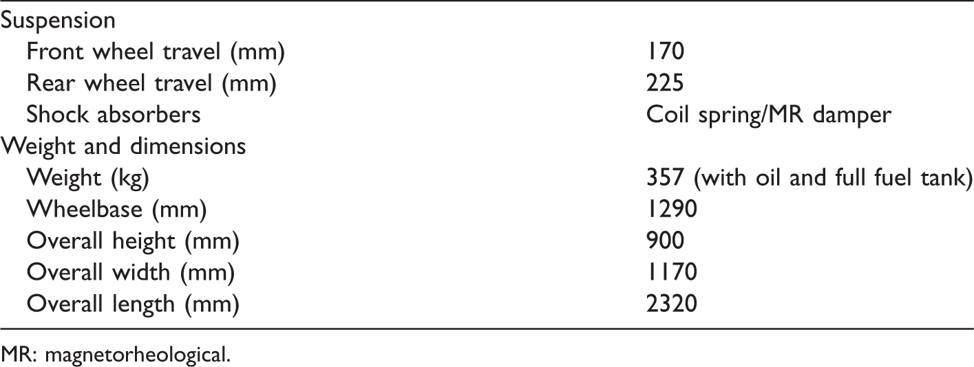
MR: magnetorheological.
Vehicle suspension control system
Scheme of the complete suspension control system, including connections between parts is presented in Figure 2. The main controller is based on a quad-core ARM single-board computer. Every quarter of the vehicle is related to a separate measurement and control unit (MCU), which is connected to the main controller via CAN bus. Each MCU is responsible for controlling a single MR damper via pulse width modulation voltage signal. It is also responsible for acquisition of measurement data from several sensors: two accelerometers (one located in the vehicle body and one close to the wheel) and a Hall effect sensor which provides information about instantaneous wheel speed. Deflection of every shock absorber is measured by linear variable differential transformer (LVDT) sensor, which is placed on the screws fixing the shock absorber. The LVDT sensor requires a dedicated signal conditioner generating output voltage signal proportional to the suspension deflection. After processing from raw AC voltage to DC voltage, data are transferred by the signal conditioner to the National Instruments single-board RIO (sbRIO) controller. The sbRIO creates a CAN frame based on the acquired data and sends it to the main controller. The sbRIO sends also an additional frame including measurements taken from two accelerometers located near the driver’s right hand on the handlebar and near the right foot on the footrest. The IMU module mounted under the driver’s seat is connected to the main controller directly via RS-232. Ride comfort, which is analysed in the manuscript, was evaluated using available accelerometers whereas vehicle handling was analysed using pitch and roll velocities taken from the IMU module. Wheel vibrations were additionally monitored using accelerometers located close to each wheel.
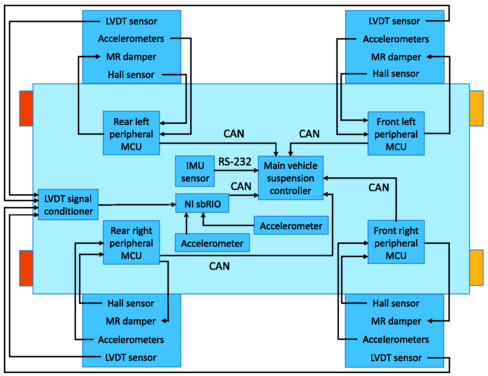
Scheme of the complete suspension control system. CAN: controller area network; IMU: inertial measurement unit; LVDT: linear variable differential transformer; MCU: measurement and control unit; MR: magnetorheological; sbRIO: single-board RIO.
Road-induced excitation
Off-road experiments were carried out in Chrobry’s Park in Gliwice, in the south of Poland. The driving test route had the shape of a rectangle, 60 m long and 25 m wide (see Figure 3), which results in a total length of approximately 170 m. It is worth noting that the suspension control system was validated in hard off-road conditions and low ambient temperature. Due to snow and slippery off-road surface a four-wheel drive mode of the vehicle was used during the experiments. The test route was characterized by the lack of sudden turnings and it has been mapped out in order to study vibrations affecting the driver and ride comfort. However, since significant unevenness of a rough road additionally influences driving safety issues, the vehicle handling was also studied.
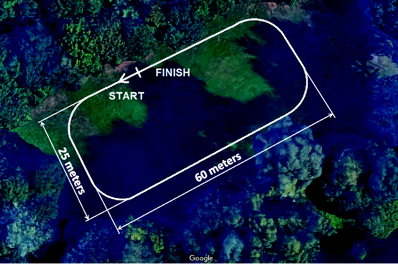
Driving test route mapped out in the field (presented based on www.google.pl/maps).
Experiments for all control configurations, including the passive suspension and Skyhook algorithm were divided into two runs related to the different average vehicle speed equal to 14 and 18 km h−1, respectively. Sample speed values averaged for all Hall sensors are presented in Figure 4. Different lengths of time diagrams result from different vehicle speeds. Three phases of the movement can be distinguished: initial acceleration, a main period of time when the vehicle speed is being stabilized and the final vehicle braking. It can be also seen that the speed depends on the shape of the route – on the straight parts the speed is slightly higher than on the curves.
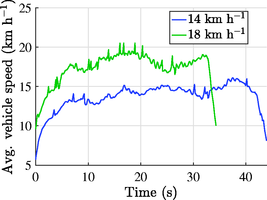
Average vehicle speed for two runs with zero damper control current.
Vibration control using MR dampers
The vibration control algorithm was performed independently for each quarter of the vehicle suspension. It was assumed that each part is separate and signals used for generation of control current for a particular vehicle quarter are measured only in this quarter. No information is exchanged between suspension controllers. Thus, the following description of the control scheme is dedicated to a separate control of a quarter-car model used, e.g. in Karnopp et al. 23
The control scheme relating to MR dampers can be decomposed into two layers (see Figure 5). The lower layer is responsible for stabilization of the force generated by the damper Fmr for a given control current imr according to the desired force denoted as Falg. The desired force is calculated by the upper layer, i.e. vibration control layer, which includes the Skyhook algorithm responsible for mitigation of the vehicle body vibration.
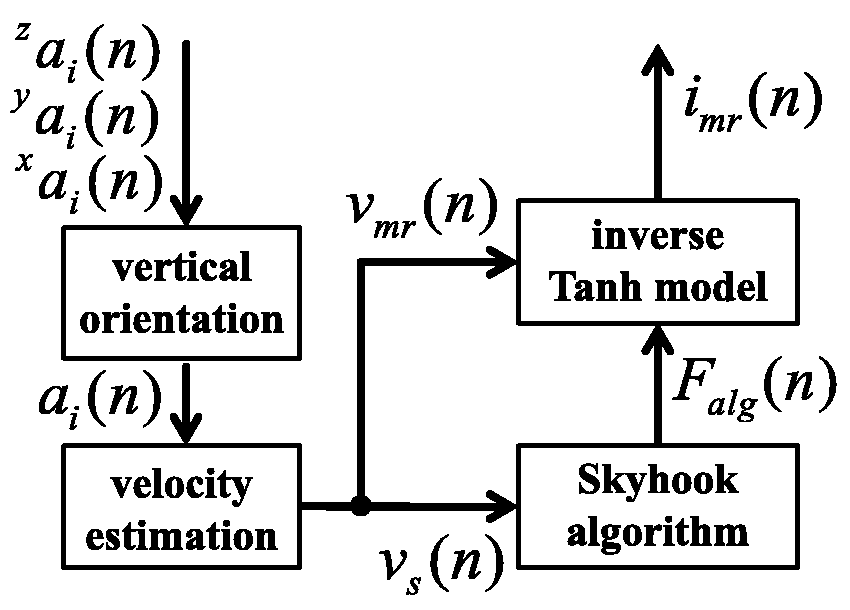
Block diagram of the semi-active control scheme, including preprocessing related to the vertical orientation of acceleration measurements and velocity estimation.
Generally, in road vehicles only a limited number of measurable signals are available and others need to be estimated. Thus, the block diagram of the semi-active control scheme includes additional signal preprocessing blocks. The first block is responsible for evaluation of acceleration signals ai, which are oriented vertically with respect to the vehicle’s coordinate system. They are evaluated based on measurements
Skyhook control
In road vehicles the Skyhook algorithm is used for stabilization of a sprung mass (vehicle body) for both road- and manoeuvre-induced excitation. Force desired by the Skyhook algorithm Falg for a selected vehicle quarter is proportional to the vertical velocity of the related body part according to the following formula

Instead of the proportional control also an on-off control can be implemented as was shown by Ahmadian, 28 where the control current can be switched between two levels related to the minimum and maximum damping value what significantly simplifies the control scheme. It corresponds to the Skyhook control applied for the greater value of the gain csh. However, in the real application the on–off control causes significant chattering of a control force and acceleration of the vehicle body, resulting in an over-tuned Skyhook and consequently it deteriorates ride comfort. Thus, the proportional force control based on an inverse MR damper model was applied.
Inverse Tanh model of the MR damper
The force generated by the MR damper can be controlled in the open loop or in the closed loop. Furthermore, modifications of both methods can be included which improves results of controlling MR damper force. For instance, Martynowicz 29 proposed an additional control block related to demagnetization and sharpening which corrects the calculated MR damper control current. Generally, the closed-loop approach is based on a control feedback which needs an additional force sensor to be installed in the shock absorber. It requires modification of the suspension system, which is an extra cost. Thus, the open-loop approach is applied instead. It requires only information about the relative velocity of the MR damper piston, which is much easier to implement. However, in this approach a model of the MR damper behaviour is needed so it has to be identified beforehand.
Selection of an appropriate MR damper model for the force control is not a trivial task. Such a model should not only map the major phenomena occurring during the MR damper operation, but it should exhibit a structure that can be easily inverted and applied in the real-time system. A model of the MR damper proposed by Kasprzyk et al.
30
was used in the presented study. It is based on Tanh function which can accurately map non-linearity of the force–velocity characteristics of the MR damper according to the following formula

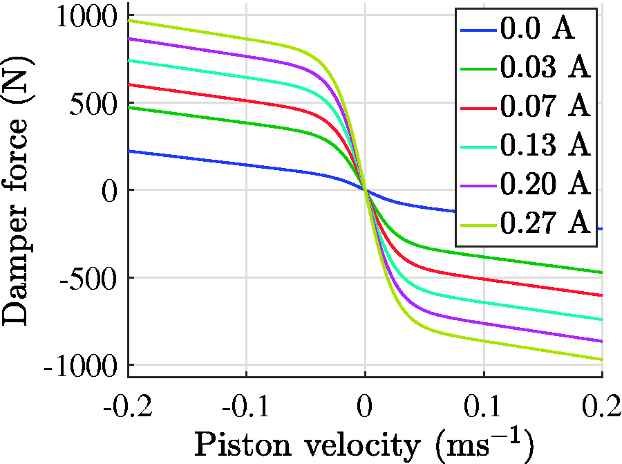
Force–velocity characteristics of the Tanh model of the MR damper for different control currents imr.
To obtain a desired current imr that enables the generation of force Fmr close to the desired value Falg, this model should be reformulated to the inverse form

Symbol 
It can be noticed in Figure 6 that only a dissipative force can be generated by the MR damper, i.e. the force can be generated only if the following condition is met

Otherwise, the inverse model (3) is not processed in order to avoid the redundant computation in the real-time implementation.
Preprocessing of measured signals
Three-axis sensors are used for acquisition of acceleration at four points of the body and at four wheels. Raw acceleration measurements are initially reoriented in space, resulting in the vertical acceleration which is further used in the Skyhook control. Additional accelerometers located on the handlebar, footrest and built in the IMU are oriented vertically and they are used directly for assessment of ride comfort and vehicle handling. These additional sensors are not used in the control algorithm.
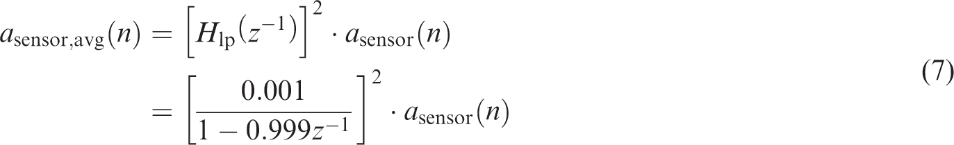
Calculated vertical acceleration includes an additional component of the gravitational acceleration which should be excluded, e.g. by subtracting its estimate in the form of the averaged value of measurements

Here
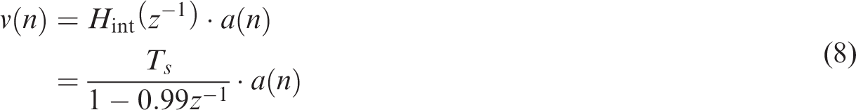
Next, absolute vertical velocities of the vehicle body parts and wheels required in the control scheme can be obtained by applying integration with inertia as follows

Analysis of vibration affecting the driver
Road experiments were conducted for two cases: constant control current imr of different values and Skyhook control with different gain csh. Initially, the analysis was focused on constant current, the same for all suspension dampers for a particular road experiment. It reflects a classical passive suspension with different damping parameters. The following values of control current were tested: 0.0, 0.03, 0.07, 0.13, 0.20, 0.27 A. Each experiment corresponds to a single vehicle ride along the off-road test route described in the ‘Road-induced excitation’ section. The analysis was done in the frequency domain on the basis of power spectral density (PSD) characteristics denoted as Sx for a certain signal x.
Acquisition of measurements
Signals from all sensors were sampled with the sampling frequency Fs equal to 500 Hz. Number of samples taken in the analysis depended on the vehicle speed (see Figure 4) and was approximately 22,500 samples for 14 km h−1 and 17,500 samples for 18 km h−1.
It was explained by Savaresi et al. 31 that analysis of ride comfort and vibrations affecting vehicle passengers is generally limited to the frequency 25 Hz. It is justified by the fact that most of the resonance frequencies of the human body are covered by such a frequency range – also confirmed by Ogonowski. 32 Thus, measurement signals used in the analysis were initially modified by a high-order Chebyshev low-pass filter with the cut-off frequency equal to 25 Hz. Otherwise, the low-pass filter eliminates the high-frequency measurement noise. It is induced by vibration of the engine or the drive system and it is not strictly related to the vehicle response to road-induced excitation. Besides, offset values were subtracted from all analysed signals.
Several signals describing the motion of the vehicle and vibration affecting the driver are used in the further analysis. Vertical acceleration of a certain wheel and a certain body part are denoted below as 
Similarly, auf and aur are evaluated as an average of the vertical acceleration of the front or rear wheels, respectively
Analysis of vibration in frequency domain
The following figures present PSD characteristics Sx obtained for selected acceleration signals, where x denotes the analysed signal. The PSD was estimated according to the method described by Welch,
33
where the number of points of the discrete Fourier transform N = 2048 and the overlap ratio for consecutive windows of analysis is equal to 0.66. Because the sampling frequency was 500 Hz, resolution of the evaluated PSD spectrum is equal to
Road-induced vibrations propagate through tires and wheels to the vehicle body simultaneously inducing vibrations of various vehicle parts with the amplitude that increases at a resonance frequency of a specific part. The averaged PSD evaluated for vertical acceleration of the front vehicle wheels is presented in Figure 7. The results are presented for different vehicle speeds and different characteristics of passive suspension determined by the value of current supplying the MR damper. A resonance peak can be noticed at frequencies from 11 to 14 Hz with the amplitude proportional to the vehicle speed. Comparison of frequency characteristics for different values of current reveals that a higher control current results in a lower resonance peak and lower amplitude of wheel’s vibration.
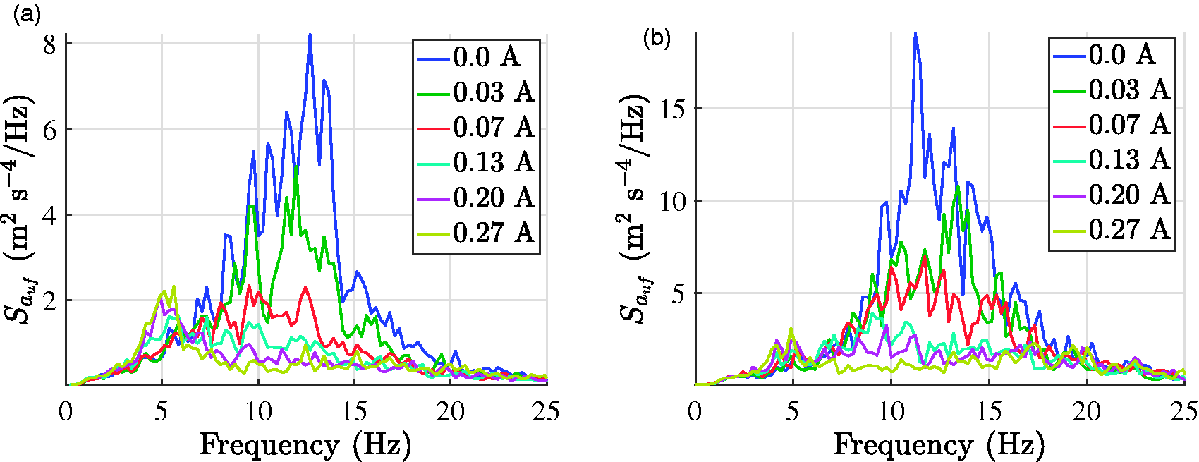
PSD of the front wheel acceleration
Most of the vehicle parts which are in contact with the driver are isolated from road-induced excitation and wheels by the suspension system. However, it appeared from the experimental results that the handlebar of the experimental vehicle was an exception. It is directly connected to the steering mechanism of the front wheels and it needs to be handled during the ride. Thus, a large part of the vibration of front wheels propagates through the handlebar and directly affects the hands of the driver. Figure 8 presents Shb evaluated for vertical acceleration of the handlebar.
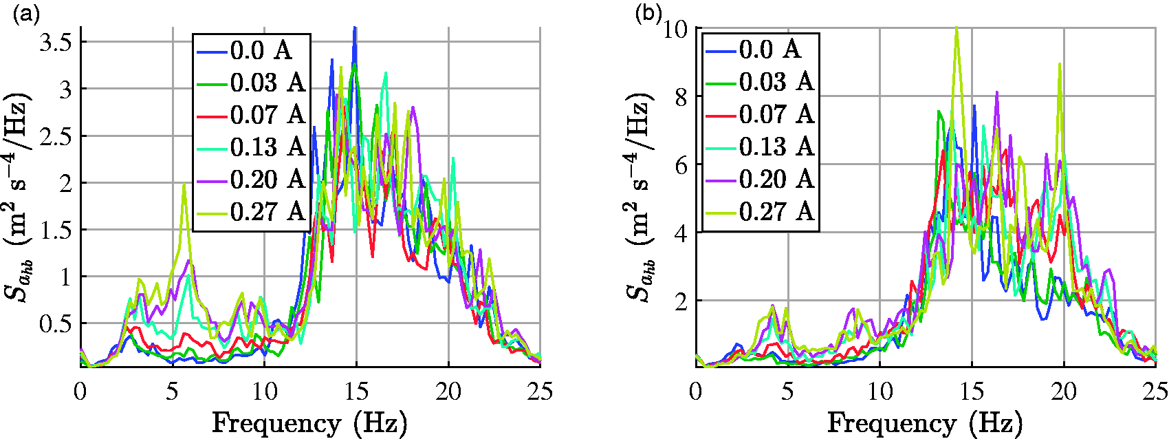
PSD of the handlebar acceleration
It can be noticed that the vibration of the handlebars in the frequency range from 0 to 11 Hz is efficiently mitigated. However, damping of vibration from 11 to 25 Hz is limited and its amplitude is comparable to that obtained for the wheel vibration which was confirmed by the driver. Such conclusions have a decisive influence on possible applications of the ATV since it requires hands of the driver to be specially protected against vibration.
Frequency analysis of vibration of the vehicle body is limited here to accelerations of the front of the vehicle asf and driver’s seat ast. Figure 9 shows frequency characteristics evaluated for asf for both vehicle speeds. For the front of the vehicle a resonance peak can be noticed at the frequency equal to 1.5 Hz for control current equal to 0 A.
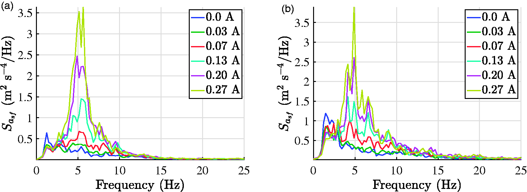
PSD of the front body acceleration
Presented characteristics indicate that the majority of high-frequency vibration is mitigated by the vehicle suspension. Besides, an invariant point can be indicated in the front vehicle part at 3 Hz. The invariant point is a point in the frequency characteristics which is independent of the suspension’s damping parameter, e.g. it can be used for determination of parameters of a mechanical system.
Furthermore, it can be noticed in Figure 9 that greater control current causes increase of the vibration amplitude and deterioration of the ride comfort. This can resemble response of a linear single degree of freedom vibratory system to harmonic base excitation where increase of a damping coefficient results in better damping of resonance peak but also increases vibration propagation for higher frequencies. For higher control current a resonance peak located at frequency equal to 1.5 Hz disappears but, on the other hand, a resonance peak at 5 Hz appears. Such a phenomenon occurs if the suspension system is stiff enough to make vibrations of the wheels and the vehicle body to be partly coupled. It should be specially taken into account for the ATV, in which the wheels are bigger with much greater width, and lower stiffness compared to road vehicles.
The driver’s seat is located in the rear of the vehicle. Thus, vertical acceleration of the seat is significantly coupled with vibration of the rear of the body which was confirmed experimentally. Frequency characteristics evaluated for seat vibration are presented in Figure 10 for different control currents. A resonance peak can be clearly indicated for both vehicle speeds at frequency equal to 1.5 Hz. Similar to the previous characteristics, the greater control current is used, the greater amplitude of vibrations. Here one can also observe that a resonance peak appears at 5 Hz for greater control current. Figure 10 confirms that vibrations of the rear wheels are significantly mitigated before reaching the seat whose vibration greatly affects the driver.
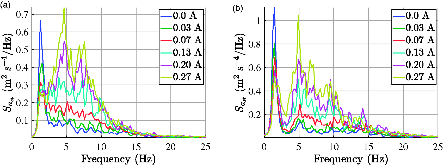
PSD of acceleration of the driver’s seat
The accelerometer close to the driver’s footrest is located approximately at the same distance from the front and rear vehicle ends. PSD characteristics obtained for the footrest’s acceleration are presented in Figure 11. The central position of the sensor allows to observe an effect of excitation of the front and rear vehicle part which are in phase and out of phase for different frequencies. The front–rear in-phase synchronization is met for selected components of the wideband excitation at frequencies fr, which are compatible with the following relation


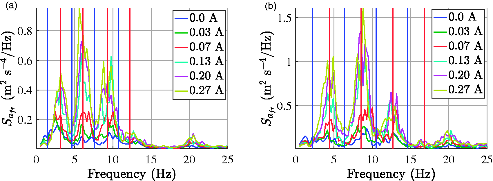
PSD of acceleration of the driver’s footrest
In-phase excitation corresponds to the peaks of vertical acceleration of the footrest while the case of 180 out of phase corresponds to the valleys with high vibration damping. Consecutive frequencies fr calculated according to equations (12) and (13) are presented in Figure 11 as vertical lines: red and blue, respectively. It can be noticed that these values are in good conformity with the corresponding frequency characteristics.
Results of ride comfort and vehicle handling
Ride comfort and vehicle handling are contradictory goals for a classical passive suspension system. Lower damping of the suspension generally leads to better isolation of passengers from road-induced vibration and improves ride comfort. However, the lower damping simultaneously makes the vehicle body to be prone to excessive pitch and rolling. In this section influence of the semi-active Skyhook control on both ride comfort and vehicle handling is considered using quality indices based on the acceleration transmissibility and the PSD characteristics. Similarly to the analysis presented for constant control current, different parameters csh of the Skyhook algorithm were tested assuming they were the same for all vehicle suspension quarters. The following values of csh were tested: 500, 1000, 1500, 2500, 3500, 4500 N s m−1. Such assumption allows to limit the number of possible experimental cases and the total time span for experiments.
Assessment of performance of vibration control
Implemented control algorithm influences mitigation of vibration which propagates from ground to the driver. Herein, it should be mentioned that the driver’s seat is located directly above the rear wheels. Thus, performance of the vibration control system is analysed here on the basis of the acceleration transmissibility which demonstrates how vibration propagates from the rear wheels to the driver’s seat and how it is mitigated. The transmissibility can be evaluated as a ratio between PSDs 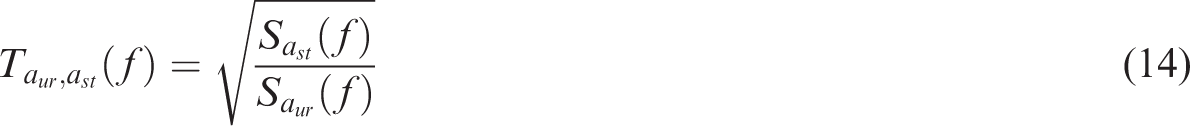
Savaresi et al.
31
presented several methods of evaluation of the ride comfort index related to performance of the vibration control system where the quality index was defined as an integral of the transmissibility spectrum within the selected frequency range. It reflects the method of evaluating root mean square values based on integral of PSD characteristics. Thus, in order to compare results of the Skyhook control obtained for different experiments, a vibration control quality index Jsh can be defined as
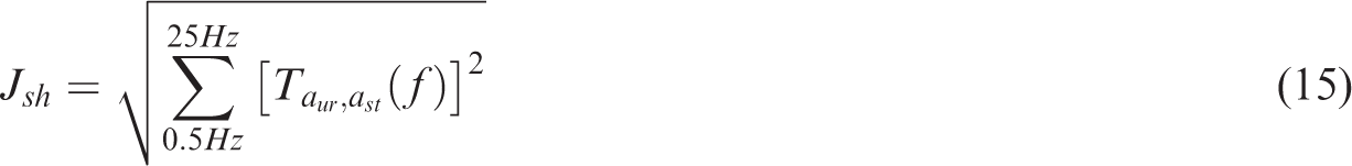
The frequency range up to 0.5 Hz is skipped as it is not related to resonance frequencies of the human body parts and also in order to reduce the effect of an offset component. The quality index Jsh is additionally normalized according to the following formula

Analysis of ride comfort
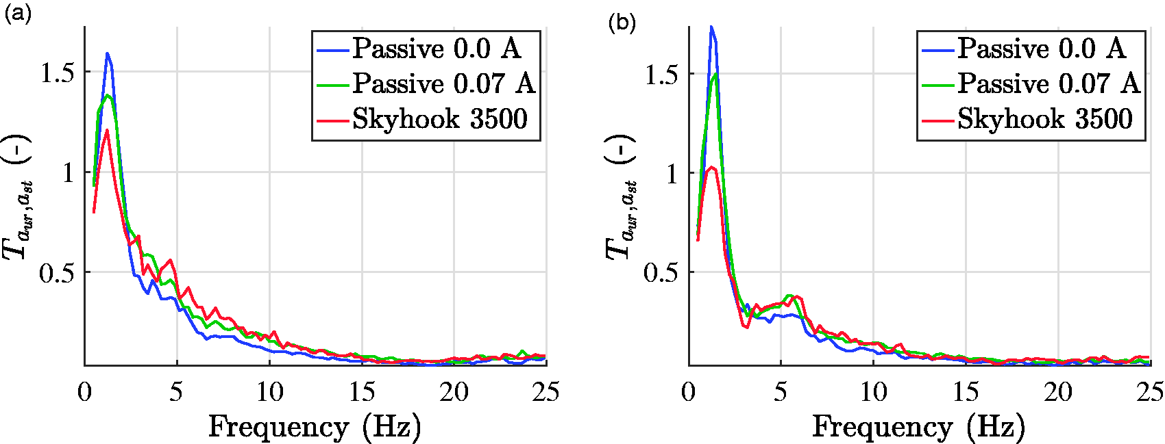
In the ride comfort analysis the vertical acceleration of the driver’s seat ast was taken into account which mostly indicate vibrations affecting the driver. Initially, in order to compare different approaches to vibration control analysis, acceleration transmissibility characteristics are shown in Figure 12 for the same cases of passive suspension as presented in the previous section. Here it can be observed that higher frequency components exhibit lower values comparing to the corresponding PSD characteristics presented in Figure 10. This is due to the fact that transmissibility is normalized based on the wheel acceleration whose higher frequency components are much greater than lower ones. Besides, it should be mentioned that the transmissibility is based on the square root of PSD. A resonance peak can be also noticed at the frequency equal to 1.5 Hz for both vehicle speeds.
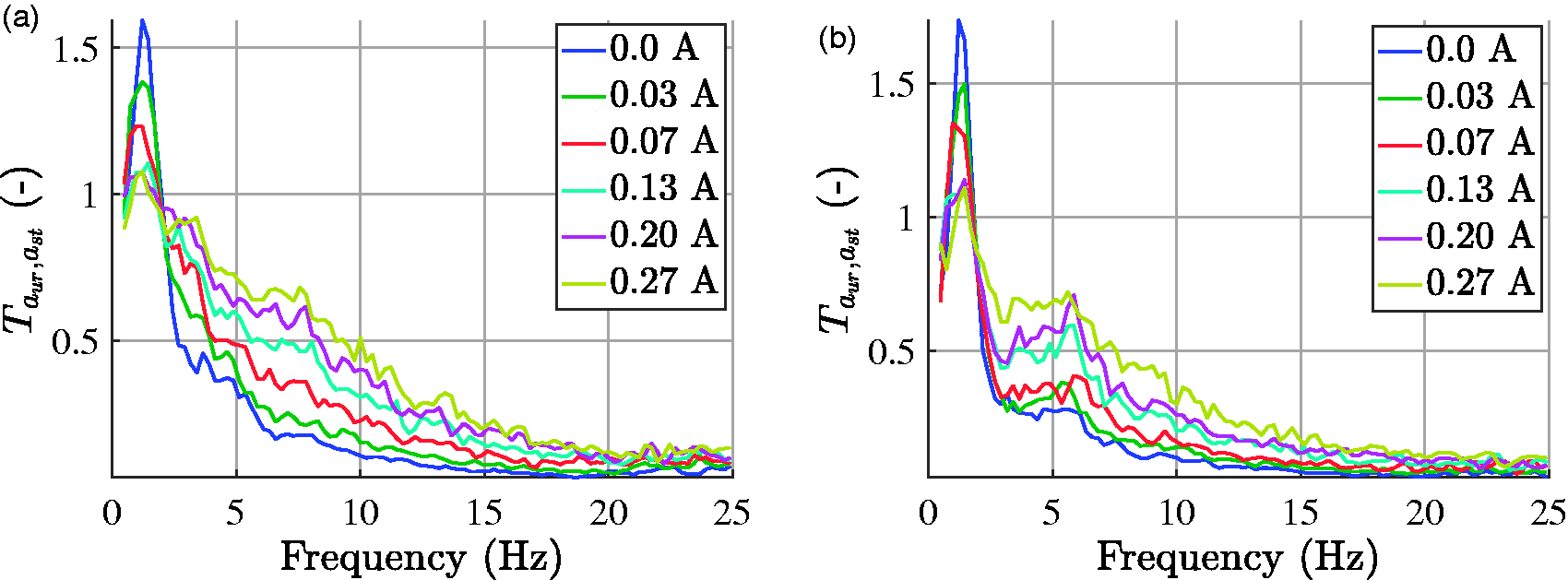
Acceleration transmissibility
The results of the Skyhook control compared with the passive suspension at zero control current evaluated for the driver’s seat acceleration are presented in Figure 13. It can be noticed that Skyhook efficiently suppresses the resonance peak of the suspension system at 1.5 Hz. Simultaneously, vibration control for the higher frequencies is only slightly deteriorated compared to the passive suspension presented in Figure 12, where similar damping of the resonance peak was burdened with a clear deteriorated vibration mitigation at higher frequencies. This improvement in the resonance mitigation was obtained for both vehicle speeds.
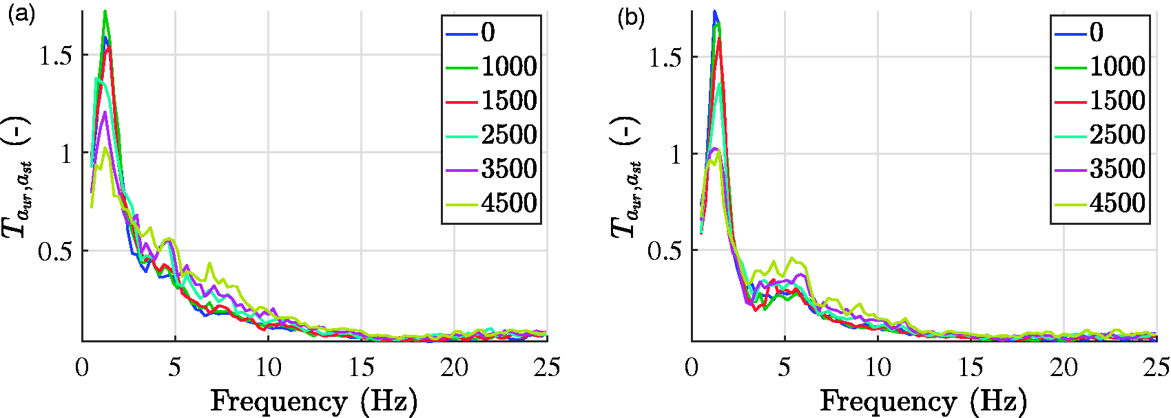
Acceleration transmissibility
Values of normalized quality indices
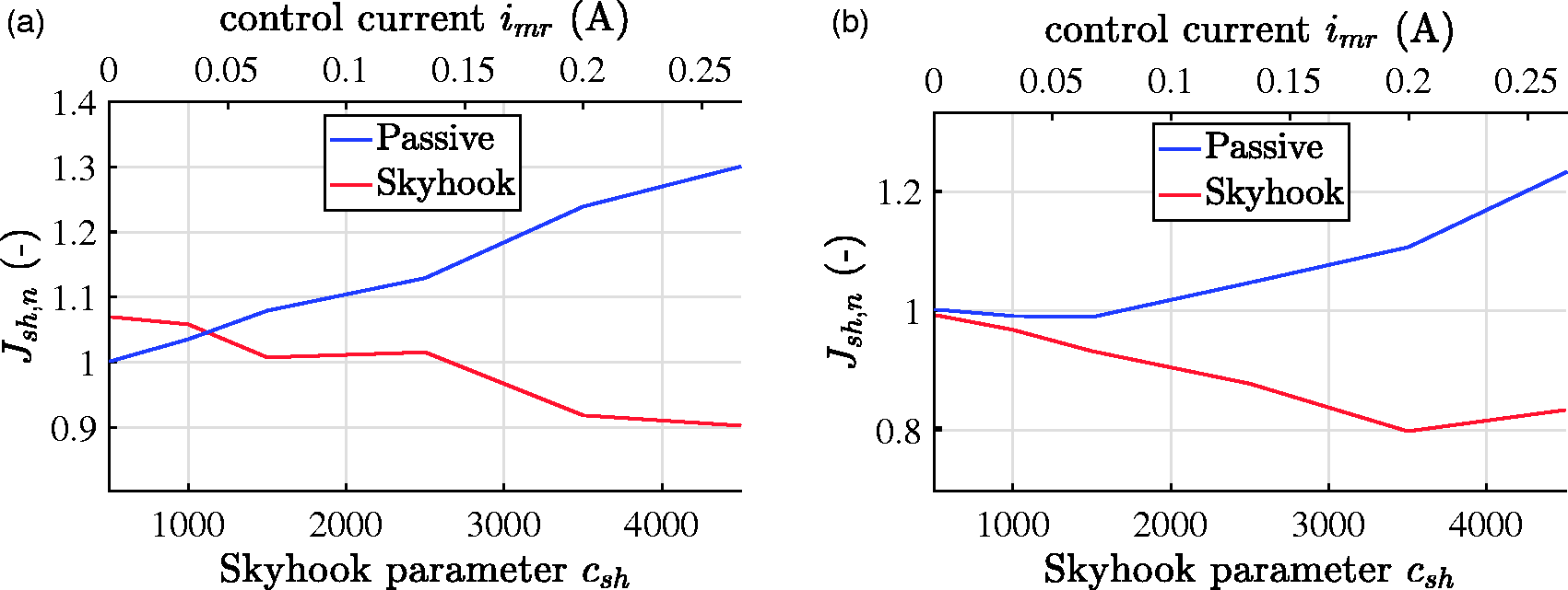
Values of the normalized vibration control quality index
The Skyhook algorithm allows for further improvement of the velocity mitigation by 10% for 14 km h−1 and 19% for 18 km h−1 for csh equal to 3500 and 4000, respectively. It can be also stated that Skyhook algorithm is robust and resistant to changes of the gain factor in a wide range for the higher vehicle speed. Contrary to the Skyhook algorithm, a slight increase of control current for passive suspension results in a significant drop of ride comfort.
Taking into account results obtained for both vehicle speeds it can be said that Skyhook parameter csh equal to 3500 is recommended for this case. Additionally, differences between the best results obtained for passive suspension and Skyhook algorithm are shown in Figure 15. Collation reveals that the Skyhook algorithm suppresses the resonance peak at 1.5 Hz and it only slightly deteriorates vibration control for higher frequencies compared to the passive suspension.
Acceleration transmissibility
In order to refer to the previous analysis based on PSD characteristics, comparison of these characteristics for the best cases of the passive suspension as well as Skyhook algorithm is presented in Figure 16. It indicates suppression of lower frequency vibration offered by the Skyhook algorithm and deterioration of vibration mitigation for higher frequencies. In order to minimize the problem of Skyhook deterioration, the following aspects should be taken into account in the future research: limited accuracy of the MR damper force control using the inverse damper model, limited accuracy of the control current imr and measurement noise generated mainly by the vehicle engine.
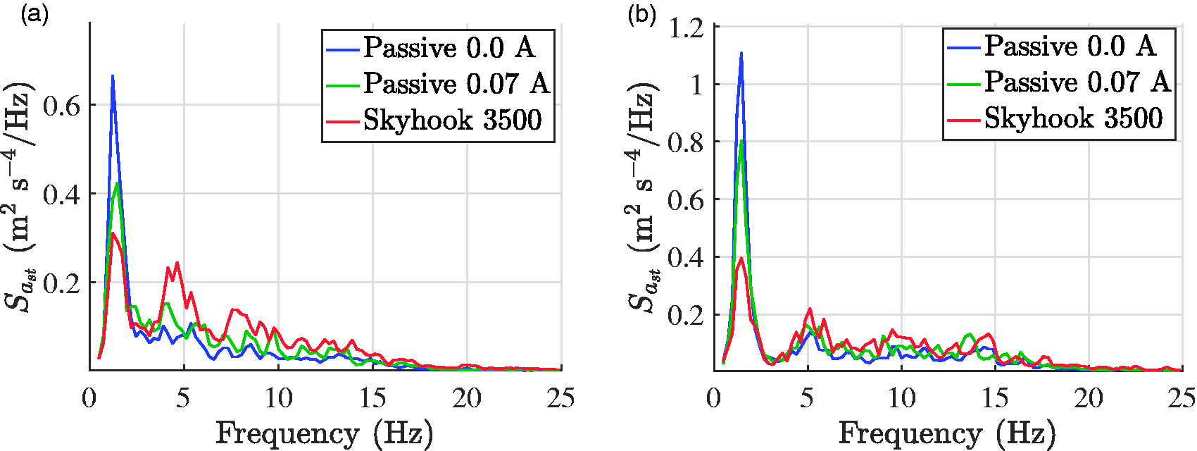
PSD of acceleration of the driver’s seat
Analysis of vehicle handling
Analysis of driving is strictly related to vehicle handling which is assessed by observation of vehicle orientation, mainly its body part as given by Uys et al. 11 Furthermore, the motion of the vehicle body influences directly passengers and the driver. Here, the vehicle handling is assessed assuming the vehicle is subjected only to road-induced excitation generated by an off-road. The goal of the suspension control system is to make variations of the vehicle body orientation as small as possible. Therefore, vehicle handling is assessed based on the pitch and roll velocities of the vehicle body denoted as ωsp and ωsr, respectively. These signals are taken from the IMU sensor located under the driver’s seat.
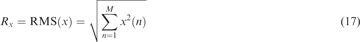
In order to compare results obtained for different experiments, root mean square values are used and evaluated as follows
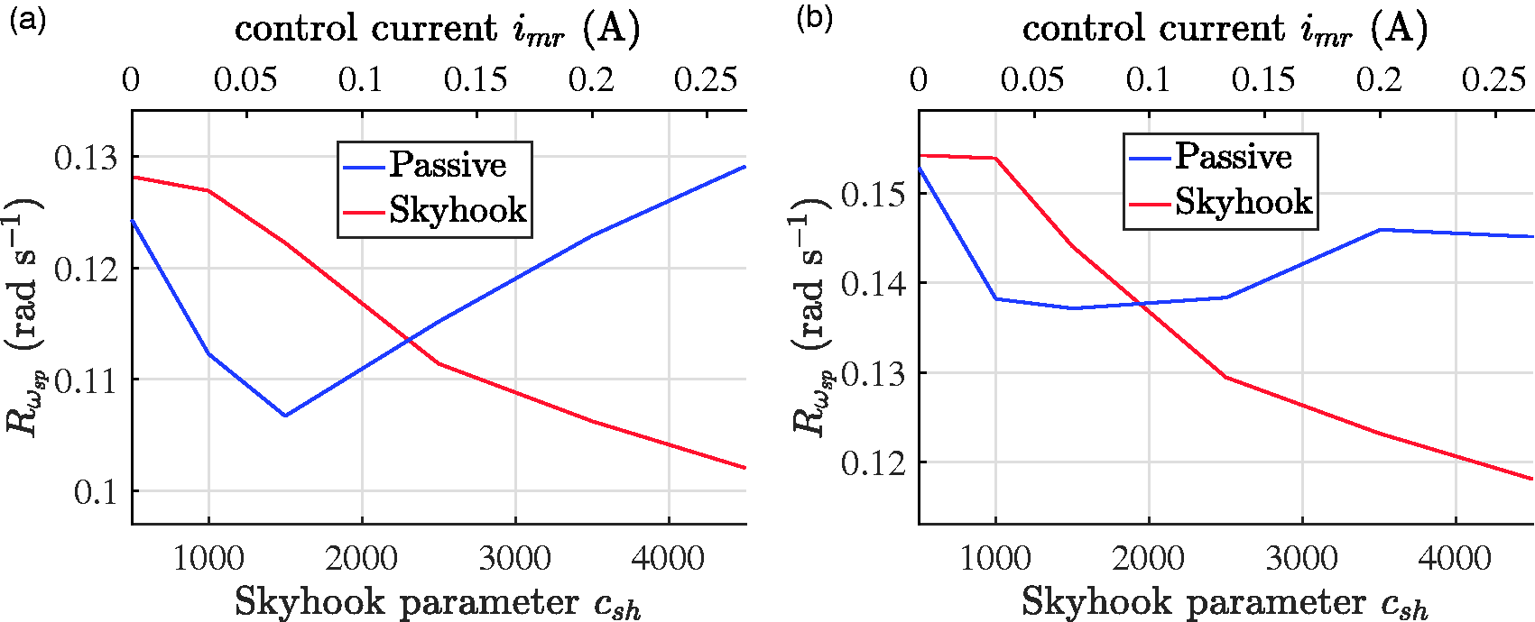
Root mean square values of the pitch angular velocity of the vehicle body
Comparison of quality indices related to the roll velocity of the vehicle body is presented in Figure 18. Here, it is indicated that the Skyhook control exhibits better results for the higher vehicle speed whereas the passive suspension gives better results for the lower vehicle speed and for control current equal to 0.03 A. It can be also noticed that lower values of the Skyhook gain are recommended for mitigation of the roll velocity contrary to the pitch velocity, where the higher values of control gain are recommended.
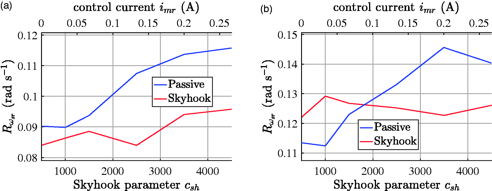
Root mean square values of the roll angular velocity of the vehicle body
Discussion of the results
Many researchers present validation of the vibration control algorithms, including Skyhook only for the harmonic excitation. The suspension control system under consideration was experimentally tested for the wideband road-induced excitation in terrain. It was shown that the Skyhook algorithm better mitigates velocity signals than acceleration signals. The authors are planning to improve the performance of Skyhook by modifying the inverse MR damper model which exhibits finite compatibility with the real MR damper as well as by refinement of the controller and algorithms of signal preprocessing. It was also shown that the selection of an appropriate Skyhook gain is important in order to reach the best possible quality of vibration control.
Vibration of different vehicle parts affecting the driver has been considered. Ride comfort was assessed based on the acceleration of the front and rear body, wheels, driver’s seat, handlebars, and footrest. The vehicle handling was evaluated based on the body pitch and roll velocities. Measurements were additionally analysed in the frequency domain and it was demonstrated that vibrations of the handlebars are comparable to the vibrations of the wheels and consequently the driver’s hands are mostly affected by the road-induced vibration at the higher frequencies.
PSD characteristics evaluated for the driver’s footrest acceleration revealed an effect of the different influence of the in-phase and out-of-phase excitation of the front and rear vehicle wheels. Thus, during the experiments carried out in the field the vehicle was subjected to the road-induced excitation of different frequencies depending on its speed and length rather than stimulated uniformly in the whole frequency range. Such phenomenon can be used in the vibration control algorithm which will be focused only on the certain frequency bands and not on those which are already sufficiently mitigated. This effect is more clearly visible for the hard suspension when the vibrations of the wheels mainly propagate to the driver’s footrest.
The vibration control algorithm influences propagation of vibration from ground and wheels to the driver located in the vehicle body. It was shown that analysis of the vibration control algorithm based on the acceleration transmissibility characteristics introduces additional information about performance of the system apart from analysis based only on PSD characteristics.
Furthermore, a methodology for testing road vehicles with different types of suspension system was proposed in the article. Application of MR dampers allows for quick changing of suspension damping parameters and emulation of different settings for the suspension system. Such approach makes the obtained results more closely related to the examined settings of the suspension and independent of different suspension designs.
The problem of engine-induced vibration is especially current for off-road vehicles where the driver is hardly isolated from unfavourable conditions including engine vibration. It was observed during the experiments that the vibrations generated by engine propagate to all parts of the vehicle deteriorating acceleration measurements used in the vibration control algorithm. More sophisticated digital filters cannot be implemented since they exhibit significant time delay which also worsens the control effects.
Finally, preprocessing of acceleration measurements and estimation of the velocity are required by the Skyhook algorithm. Selection of the filter parameters is crucial. Too large value of the time constant of the integration filter would cause long decaying of integration errors, whereas too small time constant would result in deteriorated estimation for the lower frequencies. In the future research, the authors will focus on the sensor fusion algorithm which will allow for improving the quality of the signal estimation and filtering of disturbances.
Conclusions
The original contribution of this paper consists of road experiments carried out for a real object, i.e. the experimental off-road vehicle with MR dampers. Due to a wide range of possible applications of a such vehicle it is required to efficiently solve the compromise between ride comfort and vehicle handling using the semi-active suspension. The vehicle is equipped with numerous accelerometers and the IMU module that allow for a comprehensive analysis in the frequency domain based on the PSD as well as based on the ride comfort and vehicle handling quality indices. Here, ride comfort was evaluated based on the root mean square of the selected acceleration signals, whereas the vehicle handling was assessed based on the pitch and roll velocity of the vehicle body.
One of the interesting issues was to analyse how vibration propagates in this vehicle and which parts of the driver’s body are mostly affected. This can constitute a recommendation for the future design of the vehicle and suspension. The Skyhook algorithm was implemented including the proportional control of the MR damper force and the inverse Tanh model of the MR damper. It was validated for the wideband road-induced excitation contrary to the commonly presented in the literature experiments performed only for the harmonic excitation. It was shown that the properly tuned Skyhook algorithm gives better results for the ride comfort and vehicle handling in the majority of cases compared to the passive suspension where MR dampers are controlled with different values of constant current. Also, a methodology for testing different settings of the suspension system was proposed by changing the control current of the MR damper.
The main effort consisted in the implementation of the control algorithm in the embedded real-time controller, synchronization of signals coming from different sensors and carrying out experiments in the field in hard conditions, like the low temperature, simultaneously with retaining the sufficient repeatability and good quality of the suspension control. It was shown that the proposed system effectively mitigates vibration propagating from ground and wheels to the driver’s seat. It should be mentioned that ambient conditions were the main limitations which influenced length of experiments and location of the test route. The maximum vehicle speed was also limited in order to keep acceptable driving safety during tests while accuracy of stabilization of the speed was finite. Moreover, since not all possible combinations of control parameters could be tested, parameters related to all suspension quarters were the same for a single experiment. Additional accelerometers attached to the driver would be recommended for measuring vibration of chest, arms or head. Assembly of force sensors in the suspension system would allow assessing quality of current controller, inverse MR damper model and estimating dynamic forces of wheels. Future research will be focused on development of the measurement and control system as well as on adaptive algorithms dedicated to the suspension systems equipped with MR dampers.
Footnotes
Declaration of conflicting interests
The author(s) declared no potential conflicts of interest with respect to the research, authorship, and/or publication of this article.
Funding
The author(s) disclosed receipt of the following financial support for the research, authorship, and/or publication of this article: The partial financial support of this research by Polish Ministry of Science and Higher Education is gratefully acknowledged.