
Abstract
The paper presents an experimental analysis of the selected feedback vibration control schemes dedicated to magnetorheological dampers, related to ride comfort and road holding. They were applied in a complex vibration control system installed in a commercially available off-road vehicle. Original shock-absorbers of the vehicle were replaced with magnetorheological dampers. The control system takes advantage of numerous sensors installed in the vehicle tracking its motion, i.e. accelerometers, suspension deflection sensors (linear variable differential transformer) and IMU module. Vibration control algorithms: Skyhook, PI, and Groundhook were tested experimentally using mechanical exciters adapted for diagnosis of a vehicle suspension system. Since the presented semi-active vibration control requires the magnetorheological damper inverse model to be applied, accurate operation of this model significantly influences the quality of vibration control. Therefore, additional analysis was related to application of measurements from accelerometers or suspension deflection sensors in the inverse model. Presented variants of control algorithms were compared by means of transmissibility characteristics evaluated in the frequency domain as well as using ride-comfort- and driving-safety-related quality indices. It was confirmed that the Skyhook control as well as PI improved ride comfort, whereas Groundhook control improved road holding and decreases vibration of the wheels. Furthermore, it was shown that both approaches to the relative velocity estimation, based on accelerometers and linear variable differential transformers, can be used in this application. However, the first solution gives better results in the case of the Skyhook and PI control, whereas application of LVDT sensors is better for the Groundhook algorithm.
Keywords
Introduction
Methods of vibration control are highly desired in the road vehicles, which are constantly subjected to road unevenness, road bumps, and holes. Vehicle vibration propagates through all parts of the vehicle, e.g. wheels and vehicle body including passengers’ seats and passengers themselves. Vibration of wheels occurring at the resonance frequency deteriorates road holding and leads to loss of adhesion to the road surface. Vibration of vehicle body causes discomfort to passengers, having a negative influence on their health as well as can damage cargo carried in the vehicle. Cempel 1 stated that the resonance frequencies of the human body mainly cover the frequency range up to 25 Hz. Such statement was confirmed by evaluation of ride comfort quality index presented by Savaresi et al. 2 The frequency range related to ride comfort should cover dominant resonance frequencies of a road vehicle, which were listed, e.g. by Hrovat. 3 Different simplified models of vehicles presented in the literature are always defined in order to map the most important resonance frequencies. The half-car model, which was applied in studies, e.g. by Prabakar et al. 4 or Malekshahi et al. 5 exhibits 4 degrees-of-freedom (DOFs) and maps vertical motion of the front and rear wheels as well as heave and pitch dynamics of the vehicle model. The full-car model used by Lagraa et al., 6 which exhibits 7-DOFs, additionally describes the vertical motion of all wheels and roll vehicle body motion. Other vehicle models take into account interactions of the vehicle with the human body as presented, e.g. by Gohari and Tahmasebi. 7
The problem of vehicle vibration is especially seen in the case of off-road vehicles, which are intended for use in difficult road conditions and are subjected to road excitation of much higher amplitudes comparing to roads of common use. Such vehicles are widely used not only for sports and recreation, but they are also exploited by emergency services in order to get to hard-to-reach places and as military vehicles for transportation purposes. Driver of the all-terrain vehicle is not protected by a cabin from undesired conditions, e.g. noise and vibration, during long drives. A method of determining the parameters of the vehicle suspension that takes into account the weighted root-mean-square vertical acceleration of the driver and passenger was presented by Uys et al. 8 Moreover, limited size of a quad applied in the presented study is demanding and limits power-consumption of suspension elements and their controllers. Els et al. 9 presented studies based on simulations of three different vehicles where it was stated that ride comfort and handling are contradictory. The problem of handling can be especially visible in the all-terrain vehicle, which exhibits high center of gravity and, thus, is prone to the excessive pitching and rolling. All-terrain vehicles should be analyzed with respect to optimization of suspension parameters and adaptive suspension systems, but currently it is rarely presented in the literature. Vehicle suspension systems need to be designed in a way, which allows for isolation from unevenness and simultaneously maintains control over the vehicle trajectory as it was given by Els et al. 9 Generally, a passive suspension can be characterized by its damping ratio, which usually ranges from 0.3 for cars of common use to 0.7 for sport cars as was given by Hyvarinen 10 while its parameters cannot be changed during exploitation. For significantly varying road conditions, it is extremely difficult to design a passive vehicle suspension system, which simultaneously meets those conflicting requirements related to ride comfort and road holding.
As a consequence, an adaptive suspension system was proposed in the literature, which allows to find a compromise between ride comfort and road holding depending on instantaneous road conditions where its different realizations can be differed based on active force generators or semi-active suspension systems. A study presented by Adibi and Rideout 11 belongs to the active solutions where an idea of using a lead vehicle of a convoy for generating a preview function for active suspension was tested in simulations. Experiments carried out by Sibielak et al. 12 for a quarter-car set-up with slow-active suspension elements were dedicated to the analysis of ride comfort, vehicle handling, and contact of the wheels with the road surface simultaneously maintaining minimum power requirements. Ning et al. 13 presented design, fabrication, and testing of an innovative active seat suspension dedicated to heavy-duty vehicles. Semi-active suspensions are favored for their inherent stability and low energy consumption, where the latter is especially desirable for mobile applications with limited energy resources. MR damper is filled with MR fluid. Its viscosity can be influenced by magnetic field induced by control current supplied to electric coils, which are built in the damper piston. Short response time of MR damper, which is 20 ms on average, as was reported by Koo et al., 14 makes the use of this device an efficient way to counteract road unevenness and vehicle vibration. Sapinski 15 presented a comprehensive analysis of MR dampers and reported their application in a driver’s seat suspension and in a pitch-plane model of vehicle suspension. Comparison of different control algorithms based on numerical simulations dedicated to MR dampers including proposed human simulated intelligent control (HSIC) algorithm was presented by Dong et al., 16 whereas the experimental results were reported by Dong et al. 17
Despite the advantages of the MR dampers, their complex dissipative behavior, as was reported by Song et al., 18 force saturation and hysteresis loops revealed in the force-velocity characteristics and shown in studies presented by Spencer et al., 19 and Sapinski 15 as a result of modeling and identification experiments require sophisticated control algorithms to be applied. Commonly, control systems dedicated to MR dampers are decomposed into two layers. The lower layer is responsible for controlling the force generated by MR damper, where application of MR damper inverse model is the most popular approach. The higher layer is aimed at solving compromise between ride comfort and road holding, and consequently at controlling vibration of certain vehicle parts.
The Skyhook algorithm introduced by Karnopp et al., 20 which belongs to the group of feedback control where vertical velocity of the vehicle body is used as a feedback signal, is the most popular and robust semi-active control scheme dedicated to ride comfort. Other researchers, e.g. Savaresi and Spelta 21 presented an extension of the Skyhook algorithm, i.e. the mixed Skyhook-ADD algorithm where the separate ADD (acceleration-driven damping) is based on the acceleration of different vehicle body parts. Furthermore, the displacement or position signal can be also used in feedback loop, which was shown by Cabrera-Amado and Silva-Navarro 22 as applied in a positioning application dedicated to MR dampers. Studies presented by Metered et al. 23 are the example of application of a proportional–integral–derivative (PID) control algorithm, where all three feedback signals (displacement, velocity, and acceleration) are used for MR-damped vehicle suspension system. The PID algorithm was optimized using a particle swarm optimization procedure. However, generally in the case of real-time implementation a compromise needs to be found between accuracy or performance and complexity of the control algorithm. The PID control dedicated to MR dampers can be also generalized to clipped optimal control. However, its disadvantage is a necessity of solving the Riccati equation, which requires higher computational effort. The solution to this problem was proposed by Moore et al. 24 The authors applied neural networks for modeling and identification a state-space model of a linear system as well as for solving the infinite-horizon Riccati equation in real time. Samath and Selvaraju 25 presented an extension of the previous work where neural networks were applied to the online solution of a matrix Riccati differential equation dedicated to a nonlinear singular system. Kurczyk and Pawelczyk 26 presented an alternative approach to the semi-active control of the vehicle body motion where fuzzy control was utilized for a full-car model of a vehicle moving over a single obstacle. The fuzzy control was applied for MR damper control without an inverse MR damper model, which is a significant advantage of the proposed control scheme.
The Groundhook algorithm, e.g. described by Savaresi et al., 2 which is in opposition to the Skyhook, is used for controlling vibration of the wheels and consequently is related to the road holding issue. Furthermore, the hybrid algorithm was proposed in the literature which is a composition of the previous two control schemes while its implementation was tested, e.g. by Dong et al. 16 Makowski and Knap 27 presented results of experiments for another approach to improve road holding. These methods were used for assessing the properties of MR suspension devices in the case of control algorithm, which was dedicated to the reduction of variations in vertical wheel forces and tire deflections. The algorithms mentioned above belong to the group of feedback control which can be generalized by the optimal control that takes advantage of all state variables. Application of optimal control for a slow-active vehicle suspension was presented by Sibielak et al. 12 An optimal control with modified quadratic performance index tested in simulations and experimentally for a quarter-car test rig was further presented by Sibielak et al. 28
Measurement system installed in a vehicle is the key element of a control system for vehicle vibration. Sensors track the motion of the vehicle and generate feedback information for a control algorithm. Measurement signals are deteriorated by multiple factors, including vibrations generated by vehicle engine or induced by tire tread located on rotating wheels, see e.g. Burdzik. 29 Thus, reducing measurement noise and uncertainty, as e.g. discussed by Wiora et al., 30 is especially important in vehicular applications. Apart from measurement noise, tracking the position of a moving vehicle is particularly difficult since any reference measurement point is hardly available. Different alternatives were proposed in the literature which are based on optical sensors, e.g. Yankun et al. 31 presented application of vision cameras in obstacle detection system, Budzan and Kasprzyk 32 discussed laser range scanners used for determination of road profile and a multi-sensory approach was presented by Yu et al. 33 Such optical sensors can generate a preview signal required by adaptive feed-forward control algorithms. However, they require high computational effort and increase cost of a suspension control system. Thus, commonly acceleration sensors are used in vibration control systems, accompanied with suspension deflection sensors, see e.g. Makowski and Knap, 27 or gyroscopes measuring the orientation of the vehicle body.
The vast majority of publications dealing with suspension control algorithms present mainly the simulation results. This paper is focused on the experimental study of the most popular Skyhook, PI, and Groundhook control algorithms applied to an experimental off-road vehicle. The purpose of the research was to investigate how the algorithms improve ride comfort and influence driving safety for uneven roads. This required the construction of a special test stand to determine the actual vehicle frequency characteristics. Also, different configurations of the measurement system were analyzed, taking into account application of additional linear variable differential transformer (LVDT) sensors and their influence on the quality of vibration control. The paper is organized as follows. The upcoming section presents the set-up including the off-road vehicle, its measurement and control system, a diagnostic station with mechanical exciters, and a method of excitation of the vehicle vibration. Next section reports applied semi-active control algorithms along with the MR damper model and the velocity estimation, while later sections present results obtained for the experimental vehicle and different control approaches, and they are concluded in the final section.
Description of the experimental set-up
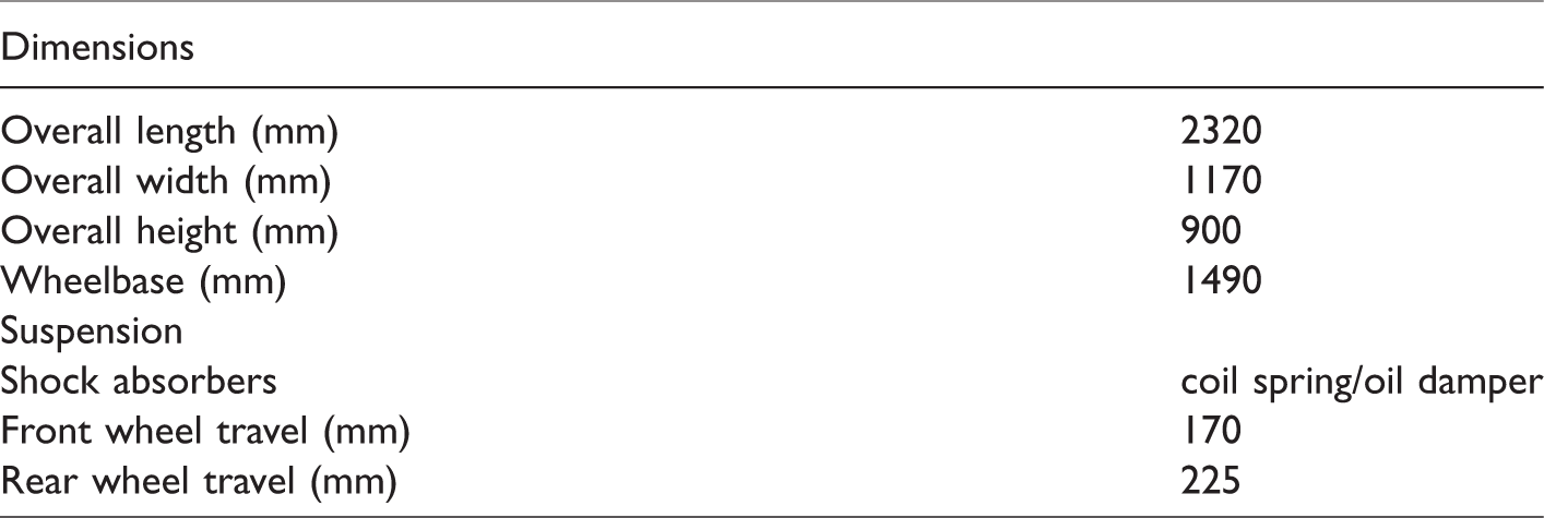
The research was carried out for an all-terrain vehicle (ATV) CF500–2A, produced by the CF Moto Company (Figure 1). Key parameters are presented in Table 1. The standard vehicle suspension was modified in order to incorporate magnetorheological (MR) dampers produced by the Lord Corporation.
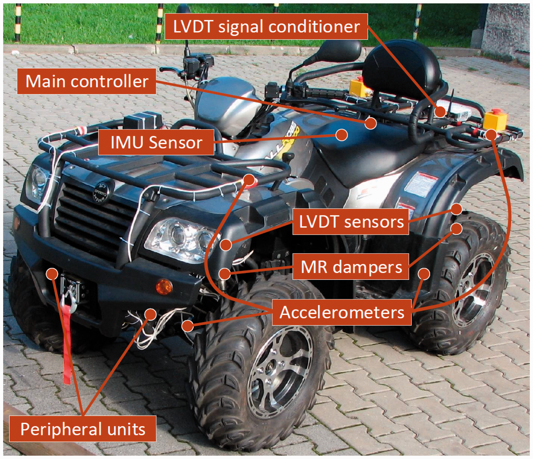
Experimental off-road vehicle with vibration control system.
Main technical data of the experimental vehicle.
The main controller is a single-board computer with a quad-core ARM processor, which is connected to measurement and control peripheral units (MCUs) via CAN bus. In every quarter of the experimental vehicle, there is a set of sensors connected to the MCU. Single set of sensors consists of two 3-axis accelerometers for measuring acceleration of a quarter of the vehicle body and a wheel, single Hall sensor for measurement of speed of the selected wheel and the MR damper which serves as an actuator in the suspension system. There is also an LVDT sensor for suspension deflection measurement, which is mounted on the same screws as the shock absorber. Every LVDT sensor is connected to a dedicated signal conditioner. After transforming measurement from LVDT to DC voltage, data are acquired by a single-board RIO from National Instruments, afterwards processed and send to the main controller via CAN. An IMU unit is an additional sensor dedicated to assessment of the driver’s comfort. Connection between the IMU sensor and the main controller is established via RS-232 (Figure 2).
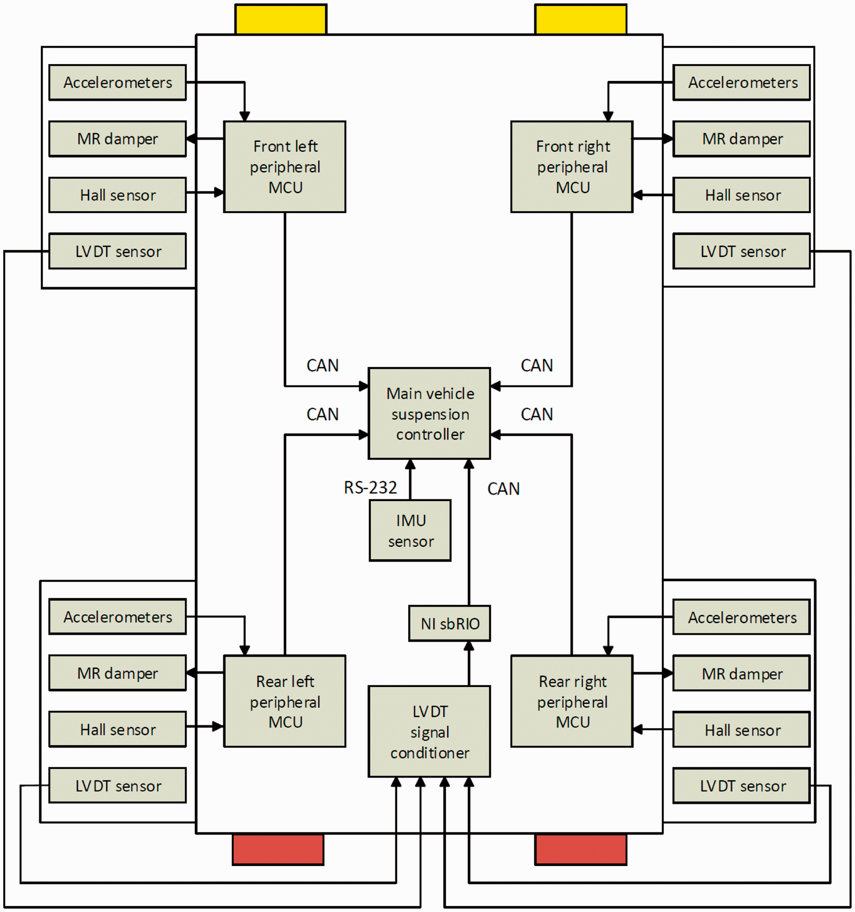
Scheme of the complete suspension control system.
Mechanical exciters for vehicle diagnosis
A modified vehicle diagnostic station was used as a measurement stand with vibration exciters (Figure 3(a)). Right and left exciters are powered by 1.3 kW asynchronous motors, each controlled by a Danfoss frequency inverter. The inverters work in a closed-loop mode, with reference and feedback signals, which sets proper vibration frequencies of the exciters. The feedback signal for the each exciter, i.e. a measurement of its frequency is generated in the form of pulse signal from a Hall proximity sensor, which is connected to a pulse feedback input of the inverter. The Hall sensor is mounted against eight magnets located on a flywheel, which is fixed to each motor (Figure 3(b)). This number of magnets allows for achieving eight times greater update rate then frequency of the exciter, which gives better measurement accuracy. A sequence of a single experiment, i.e. the desired vibration frequency and its duration are controlled by a Schneider programmable logic controller (PLC) via its analog voltage outputs connected to the analog reference inputs of the inverters.
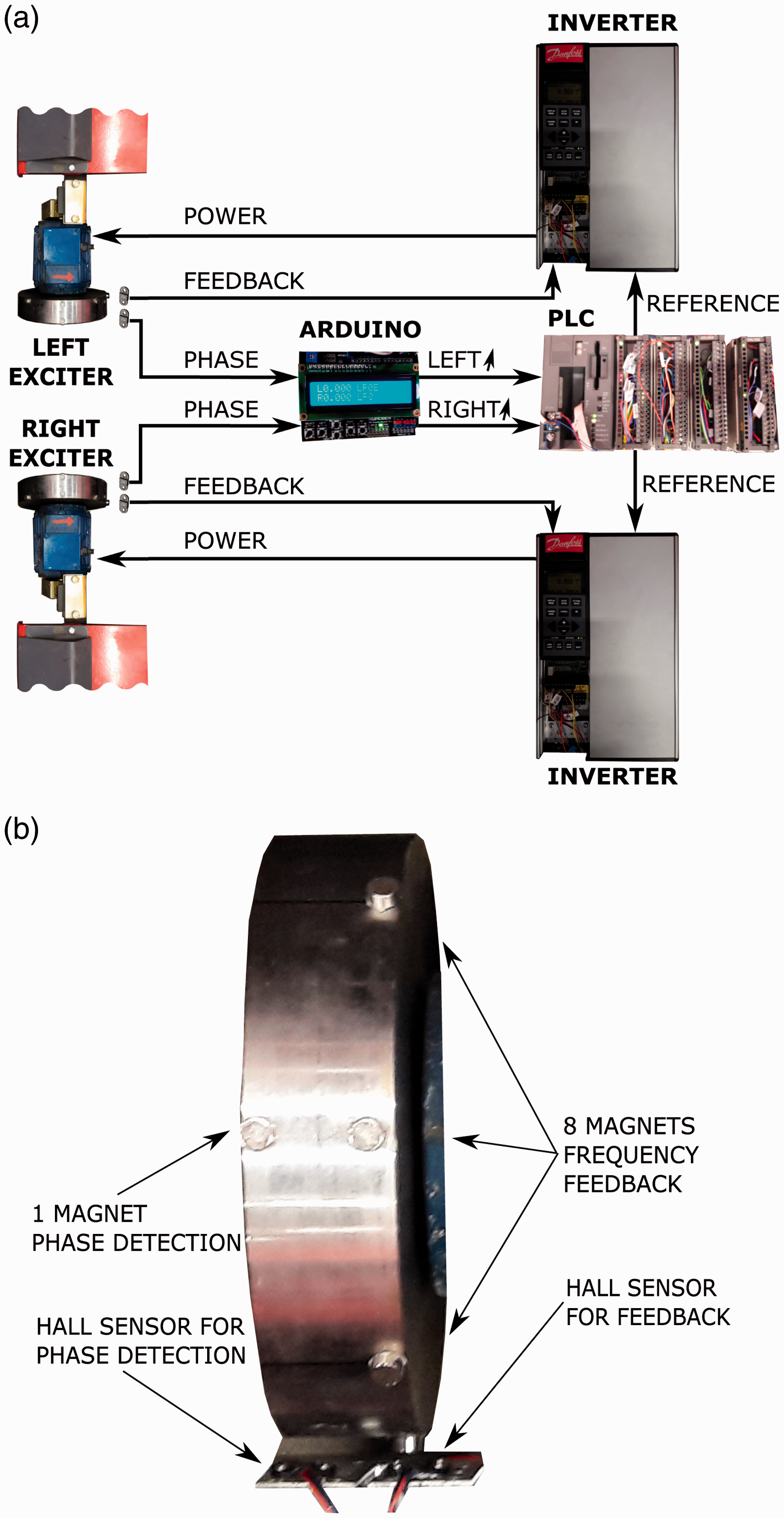
Experimental set-up with mechanical exciters: (a) block diagram of exciters control system, (b) location of Hall sensors and magnets on the flywheel.
A second control loop was implemented in order to keep the vibrations of both exciters in the same phase. It takes the advantage of a second Hall sensor located on each flywheel, opposite to only one magnet, which is used for phase shift detection. This pair of Hall sensors of both motors is connected to the Arduino Uno board which measures the frequency of rotation of the motors and the phase shift. Next, it sends information to the PLC if speeding up one of the motors is necessary in order to compensate the phase shift. Experiments indicated that the presented control system of the vibration exciters keeps the desired frequency with accuracy of ±0.1 Hz and phase shift at range ±20° about 5 s after setting a new frequency (Figure 4).
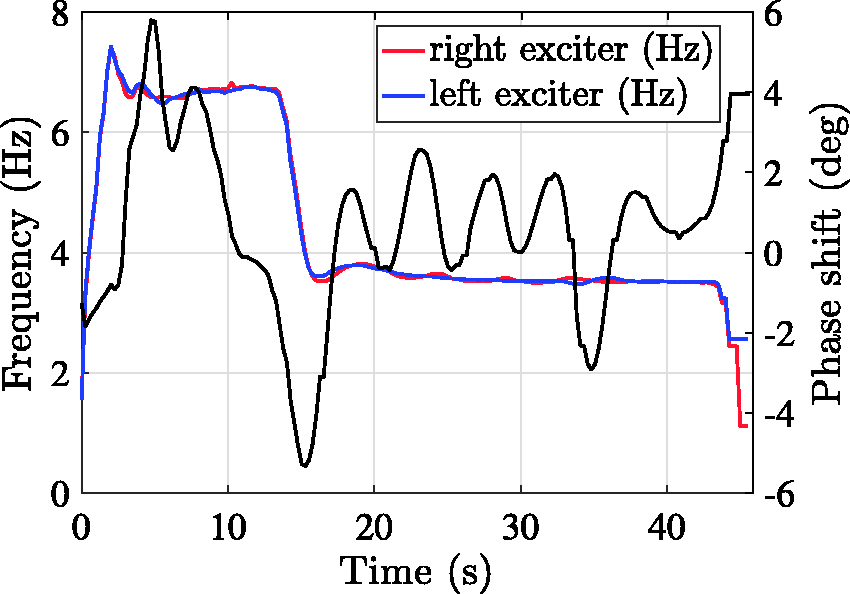
Results for vibration generated at 3.5 Hz including a speedup phase at 7 Hz for the first 15 s followed by the measurement phase. Red line – frequency of the right exciter. Blue line – frequency of the left exciter. Black line – phase shift between right and left exciters.
Response of the vehicle suspension to ground vibration was examined for frequency range from 1.5 Hz to 12.0 Hz at intervals of 0.5 Hz. Since damping parameter of each exciter is very small, it tends to vibrate at high amplitude for frequencies close to 9 Hz, which is close to the resonance frequency of wheels of the vehicle. Thus, in order to avoid damage of the experimental set-up, excitation frequencies from 8.0 Hz to 9.5 Hz were omitted during experiments.
Each experiment consists of three phases: start-up, measurement and relax. During the start-up phase, which lasts for 15 s, the motors accelerate to higher rotational speed, independent of measurement frequency, in order to reach a steady state of frequency-related and phase-shift-related controllers. In the second phase, the exciters operate at measurement frequency defined for the experiment. This phase lasts 30 s to acquire sufficient amount of measurement data for a steady-state of vibration excitation. During the third phase, which lasts 30 s, both motors stop in order to avoid their overheating.
Vibration excitation
This study is focused on results obtained for the front part of the experimental vehicle subjected to vibration excitation generated by two mechanical exciters acting on the right and left wheel (Figure 5). The steering wheel was blocked in order to obtain repeatability over consecutive experiments. Since no driver was required during experiments, influence of a driver on the dynamics of the vehicle was neglected in the analysis. Elements of the vehicle related to vibration excitation, wheels and body are denoted by r, u, and s, respectively.
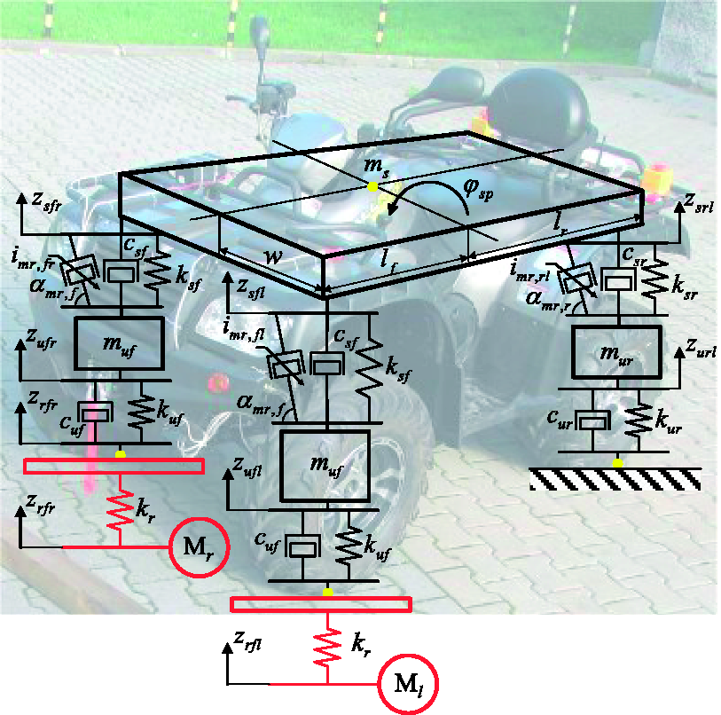
Experimental vehicle subjected to vibration excitation generated by mechanical exciters.
The vehicle and exciters create a set of interacting vibrating elements, where stiffness of a single exciter denoted as kr and stiffness of a single front wheel tire denoted as kuf can be substituted by a replacement stiffness (after neglecting the damping parameter of the tire denoted as cuf). Such combination changes the resonance frequency of a wheel which is to be examined in experiments. However, this analysis is neglected in the presented studies. The results were obtained for exciters operating in phase, which induce mostly vertical vibration of the vehicle front part. Thus, the vibrating system can be simplified to 3-DOF system, consisting of two masses of the front wheels muf and the vehicle body mass ms. Dynamic behavior of the vehicle is influenced by MR dampers, apart from passive invariant stiffness and damping element denoted as csf and ksf, respectively.
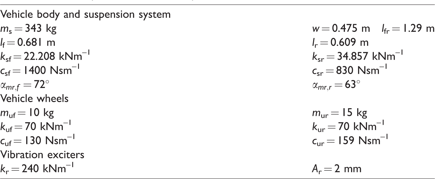
Selected parameters of the experimental off-road vehicle were measured or estimated, and they are presented in Table 2 in order to give comprehensive information about the vehicle. Masses of wheels denoted as muf and mur were measured, whereas the mass of the vehicle body ms was estimated using an actual mass of the whole vehicle and wheel masses. Similarly, distances lf and lr were also measured. Inclination angles of MR dampers in the front and rear of the vehicle, denoted as
Selected parameters of the experimental off-road vehicle.
Excitation generated by the mechanical exciters can be modeled as sinusoidal according to the following formula

Mainly, two modes were analyzed during experiments, i.e. vertical vibration of the vehicle body front part and vertical vibration of front wheels. The body vibration can be described by a vertical displacement of the center of the body front part denoted as zsf, which can be calculated as an average of the front right zsfr and front left zsfl vertical displacement. Vibration of the front vehicle body can be also described by a pitch motion denoted as
Control of the vehicle suspension system
Algorithms for semi-active control were implemented and applied independently for each quarter of the vehicle. All vehicle parts were controlled simultaneously, although, no information was exchanged between the quarter-car controllers. Thus, the following description of the algorithms is given for a single quarter of the vehicle as presented in Figure 6.
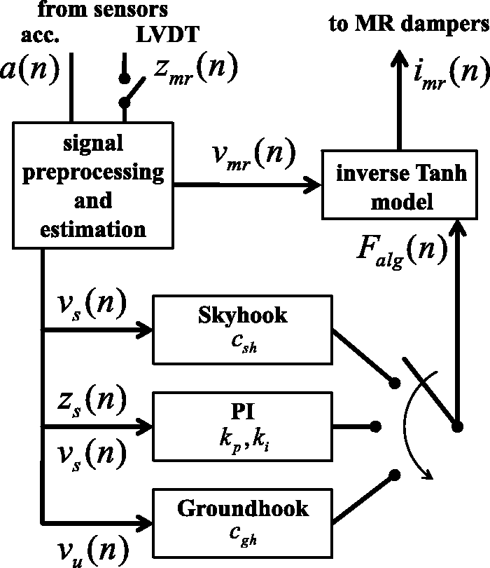
Block diagram of the semi-active control scheme dedicated to a single quarter of the vehicle.
Semi-active control related to MR dampers is commonly decomposed into two layers: MR damper force control and vibration control. Since only a limited number of signals is given by the measurement system, an additional processing block was introduced, which is responsible for estimating immeasurable signals required by control algorithms (discussed in detail in the next subsections). The implemented control scheme takes advantage of the measurements taken from the accelerometers located in the vehicle body and close to the wheels, denoted here as a. Besides, signals from LVDT sensors measuring suspension deflection zmr can be used as the other option for vmr estimation. Different tested alternatives of the vibration control were marked using switches.
Another element of the control scheme is related to vibration control and it is responsible for motion damping of a certain part of the vehicle. Depending on the selected control algorithm, i.e. Skyhook with parameter csh, PI with parameters kp, ki or Groundhook with parameter cgh, the vibration control layer is focused on damping of vibration of the vehicle body or the wheels. The selected algorithm generates a desired control force Falg based on the estimated signals of the absolute vertical velocity of the body part vs or the velocity of the wheel vu. Tested vibration control algorithms are described in the next subsection.
Generated Falg is then applied into the inverse model of the MR damper. It is responsible for converting the desired control force to the appropriate control current imr applied to the MR damper. It should result in force generated by the MR damper, close to Falg. The inverse model additionally uses an estimation of the relative velocity of the MR damper piston vmr according to the description presented in the next subsections.
Classical approach to vibration control using MR dampers
Three algorithms included in the vibration control layer were tested. Firstly, the studies were focused on algorithms related to ride comfort, i.e. Skyhook and PI, which can be assumed as an extension of the former one. Next, the Groundhook algorithm was examined that is strictly related to the road holding issues. The algorithms were implemented in the proportional form as opposed to the on-off method of controlling MR dampers, which is based on switching the MR damper control current between only two values. The proportional method means that the desired force Falg generated by the control scheme is proportionally converted into the control current using the inverse MR damper model. Validation of the on-off form was not considered, as usually this form deteriorates the quality of vibration control in comparison with the proportional one.
Skyhook control is used in the road vehicles for mitigation of vibration of the vehicle body. Thus, it is often identified with the ride comfort issue in the case of road-induced excitation. However, in the case of maneuver-induced excitation, the Skyhook tends to stabilize the orientation of the vehicle body and improves vehicle handling, which is partly related to driving safety issues. The desired force generated by the Skyhook is dependent and proportional to the absolute vertical velocity of a certain vehicle body part as follows

The PID control algorithm is commonly used in real-time applications due to its reliability and robustness. In the case of vibration control of vehicle suspension systems a set value, which is fed to the controller, is commonly equal to zero since the goal of the algorithm is to minimize vibration. Thus, the PID algorithm can be simplified to the sum of three feedback loops dedicated to the displacement, velocity and acceleration as was presented in Talib and Darus 34 and Metered et al. 23 Furthermore, it is worth noticing that a classical idea of the gain scheduling, which is dependent on the set value does not fit in this case. However, other approaches to the gain scheduling dedicated to the semi-active dampers were presented in the literature, where the scheduling is dependent on the dominant frequency of the sinusoidal road-induced excitation 35 or on a general class of the road excitation. 36
A control force desired by the PID algorithm can be formulated as follows

Preliminary studies of the PID algorithm were carried out in simulations for a quarter-car model 20 and a full-car model (Figure 5) in order to limit the number of different possible combinations. Both, the D (corresponding to the ADD algorithm) and PD (corresponding to the mixed Skyhook-ADD algorithm) gave unsatisfactory results for the given vehicle model. Only quality of the vibration control obtained by the PI algorithm (corresponding to the velocity and displacement feedback) was promising, so it was further implemented and tested experimentally.
Groundhook control is used in road vehicles for mitigation of vibration of the wheels and consequently it is identified with the road holding issues. The desired force generated by the Groundhook is dependent on the absolute vertical velocity of a certain vehicle wheel as follows

Inverse model of the MR damper
MR damper control can be realized in two manners, i.e. using the open-loop and closed-loop force control. The closed-loop approach needs force sensors to be mounted within the suspension system or shock-absorbers. It usually requires redesigning selected parts of the suspension system and increases cost of the semi-active suspension system. Thus, the open-loop approach is more popular in research studies and commercial applications of MR dampers. The open-loop force control takes advantage of the MR damper model which is identified off-line for a selected range of the excitation frequency. Next, the inverse form of the model is evaluated and used in semi-active control. Since inversion is required, structures of MR damper models that are analytically invertible are more popular than noninvertible ones. In this study, a Tanh MR damper model proposed by Kasprzyk et al.
37
is used. Parameters of the model were estimated by an identification procedure for an MR damper manufactured by the Lord Corporation. During experiments performed using the MTS (material testing system) the damper piston was subjected sinusoidal excitation at frequency equal to 1.5 Hz. Minimization of the mean squared error between the measured force and Tanh model response was the goal of the identification algorithm and resulted in model parameters presented below. Considered Tanh MR damper model is described by the following equation

This model can be reformulated resulting in the inverse model, as follows


Symbol
Furthermore, in order to avoid redundant computation processed by the real-time controller Falg is tested whether it is a dissipative force. The inverse model is used only if the following condition is met

Otherwise imr is set to zero.
Algorithms for signal preprocessing and estimation
Acceleration measurements, which are a key element of the considered suspension control system, are acquired in three coordinates using three-axis accelerometers. Since operation of vibration control is focused on vertical vibration of the vehicle, raw measurements need to be initially reoriented resulting in signals of the vertical acceleration of the selected vehicle part. Furthermore, estimated signal of vertical acceleration consists of two components related to vibration of the vehicle and gravitational acceleration. Thus, the gravitational component needs to be excluded by subtracting the averaged value of acceleration


The absolute vertical velocities of the vehicle body parts and wheels are estimated by integration with inertia as follows

For the integral component of the PI algorithm the displacement feedback signal was obtained by further integration of the vertical velocity using the same digital filter with inertia

Further results indicate that an estimation method of the damper relative velocity vmr, used in the inverse model, has decisive influence on the quality of vibration control. Two methods of vmr estimation were considered, i.e. the accelerometer-based (Acc-based) and LVDT-based method. The Acc-based method takes advantage of the velocity signals estimated according to equation (11) and the following equation

The second estimation method directly uses suspension deflection measurement zmr taken from the LVDT sensor. Now, the relative velocity is estimated by the simple differentiation of suspension deflection measurement as follows

There are more advanced methods of the velocity estimation, as e.g. second-order differentiation. However, they lead to an increase in the delay time in the control path and hence are not used here. The relative velocity could also be measured with a linear velocity transducer (LVT). However, this would require a change in the suspension structure, which is not possible at this stage of the research.
Experimental analysis of the off-road vehicle
Several experiments were performed and different scenarios were validated, including constant control current as well as Skyhook, PI, and Groundhook algorithms. Also, both methods of the relative velocity estimation were examined. Analysis of the semi-active vibration control was carried out using two approaches: the frequency domain approach based on transmissibility characteristics, and time domain approach based on ride comfort and road holding quality indices.
The data set used for the analysis of a single experiment consists of 18 sequences, where each is related to the different frequency of excitation, ranged from 1.5 Hz to 12.0 Hz. However, during the experiments wheels vibration with high amplitude occurred for excitation within the frequency range from 8.0 Hz to 9.5 Hz. Thus, this range was omitted during experiments, as it was mentioned in section, in order to avoid damage of the experimental set-up.
All measurement signals are sampled during the experiments with the sampling frequency equal to 500 Hz. Data used for further analysis performed for a certain excitation frequency are selected in two stages. The first stage corresponds to pre-selection of a 20-second-long period of time, which is related to the most stable operation of the exciters and their controllers. The second stage of selection corresponds to the final 10-second-long period of time (5000 samples) relating to the stable and proper operation of the phase-shift controller, which aims at in-phase excitation of the right and left vehicle wheels.
Analysis in the frequency domain
Transmissibility characteristics are commonly used for the analysis of mechanical vibrating systems. Here, transmissibility is evaluated based on the results obtained from consecutive experiments performed for a ground excitation in the form of sinusoidal excitation with the different frequency. Herein, motion of the front wheels as well as of the front part of the vehicle body are analyzed. The vehicle body transmissibility, denoted as 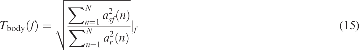
Consecutive points of
The analysis of wheels vibration is performed in the frequency domain using the wheel transmissibility 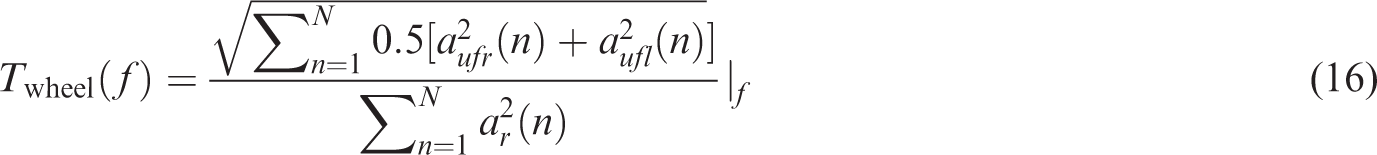
Ride comfort and road holding
The ride comfort quality index is generally related to the analysis of vibration power estimated based on measurements of vertical acceleration, which was recently confirmed in Savaresi et al.
2
In order to fulfil this assumption the other authors proposed to evaluate the ride comfort quality index as an integral within the selected range based on squared transmissibility characteristics. This approach is closely related to the method of power evaluation for a signal based on its power spectral density. Thus, the ride comfort was evaluated for the purpose of the presented research based on vehicle body transmissibility within the frequency range from 1.5 Hz to 12.0 Hz as follows

Similarly to the definition of ride comfort, the road holding quality index was made closely related to the power of the wheel vibration and evaluated within the frequency range from 1.5 Hz to 12.0 Hz as follows

Presented quality indices of ride comfort and road holding are additionally normalized according to the following expression

Passive suspension system
The first group of experiments was related to the analysis of the semi-active suspension system with constant control current imr feeding the MR dampers. The following current values were tested: 0.0 A, 0.02 A, 0.03 A, and 0.07 A. Results of experiments in the form of transmissibility characteristics are presented in Figures 7 and 8 for wheel and vehicle body vibration, respectively.
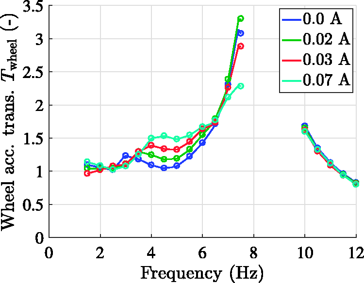
Wheel acceleration transmissibility evaluated for different control current imr.
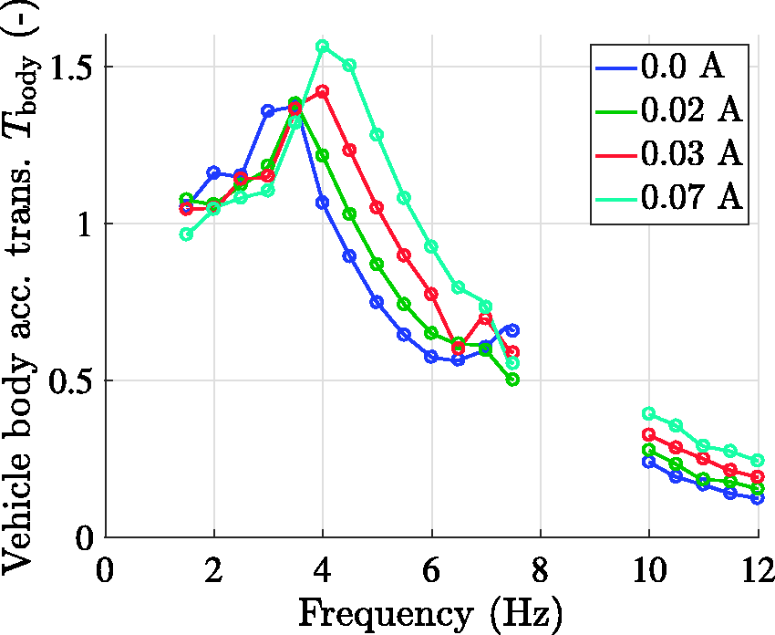
Vehicle body acceleration transmissibility evaluated for different control current imr.
The wheel transmissibility characteristic clearly shows the resonance frequency of the wheel at approximately 8.5 Hz. The second resonance frequency slightly visible at 3.5 Hz for zero-control-current suspension system corresponds to the resonance of the vehicle body. In the case of passive suspension, changing its damping parameters increases or decreases the transmissibility close to the resonance frequencies. Some points of the transmissibility, i.e. invariant points as shown in Savaresi et al. 2 are independent of the damping parameters. The invariant points can be used for derivation of parameters of the mechanical system. In the case of presented wheel transmissibility characteristics two invariant points can be noticed at 3.5 Hz and 6.5 Hz. The second invariant point was revealed despite the fact that the experiments for frequencies from 8.0 Hz to 9.5 Hz have to be omitted.
The resonance of the vehicle body can be confirmed by its transmissibility (Figure 8) at the frequency of 3.5 Hz. Similarly to wheel vibration, the vehicle body transmissibility reveals an invariant point clearly visible at 3.5 Hz. Consequently, normalized ride comfort and road holding quality indices were evaluated for the given transmissibility characteristics and presented in Table 3.
Normalized ride comfort and road holding for invariant control current.
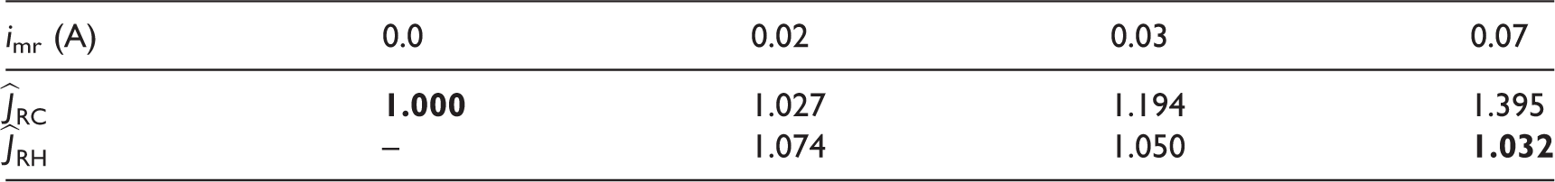
Note: The best index values are marked in bold.
Values of ride comfort quality index increase for increasing control current. Thus, it can be concluded that the most comfortable vehicle suspension is offered for the lowest control current and the softest suspension system. Contrary to ride comfort, the best road holding can be obtained for the highest control current and the hardest vehicle suspension.
Results of vibration control
Similarly to the analysis of the passive suspension, semi-active control algorithms described in section Control of the vehicle suspension system were validated in the frequency domain using transmissibility characteristics and in time domain using ride comfort and road holding quality indices. Of course, proper tuning and parameter adjustment for Skyhook or Groundhook algorithms is important. For smaller control gain the algorithm is under-tuned and not fully exploits the possibilities offered by semi-active suspension system. On the other hand, the greater gain factor causes the suspension system is over-stiffened and exhibits phenomena characteristic for hard suspension. Thus, the process of tuning is critical for good quality of vibration control and could be automatized and improved using some auto-tuning procedure. However, it is not considered in this paper.
Skyhook and PI control
Because the analysis of the Skyhook control is strictly related to ride comfort issue, so it is based mainly on the vehicle body transmissibility and ride comfort quality index. Parameter of the Skyhook algorithm csh was the same for all quarters of the suspension system in a particular experiment. According to previously discussed methods of the relative velocity estimation, two alternatives: Acc-based and LVDT-based Skyhook control were validated. Preliminary search for the optimal gain indicated that in the case of Acc-based Skyhook control the best results of ride comfort can be obtained for csh ranging from, 1000 to 3500. In the case of LVDT-based control the best results were obtained for csh within the range from 600 to 1250.
Transmissibility of the vehicle body is presented in Figure 9 for five values of csh: 1000, 1500, 2500, 3000, and 3500, in Acc-based Skyhook control. This parameter was selected in order to show the operation of the Skyhook control from the under-tuned case (csh = 1000) to the over-tuned case (csh = 3500). Similarly to results obtained for the passive suspension system, an invariant point can be noticed here at the frequency equal to 3.5 Hz. Visual inspection of the vehicle body transmissibility suggests that the best results can be obtained for csh = 2500, where the resonance peak is significantly decreased and quality of vibration mitigation is not deteriorated for higher frequencies.
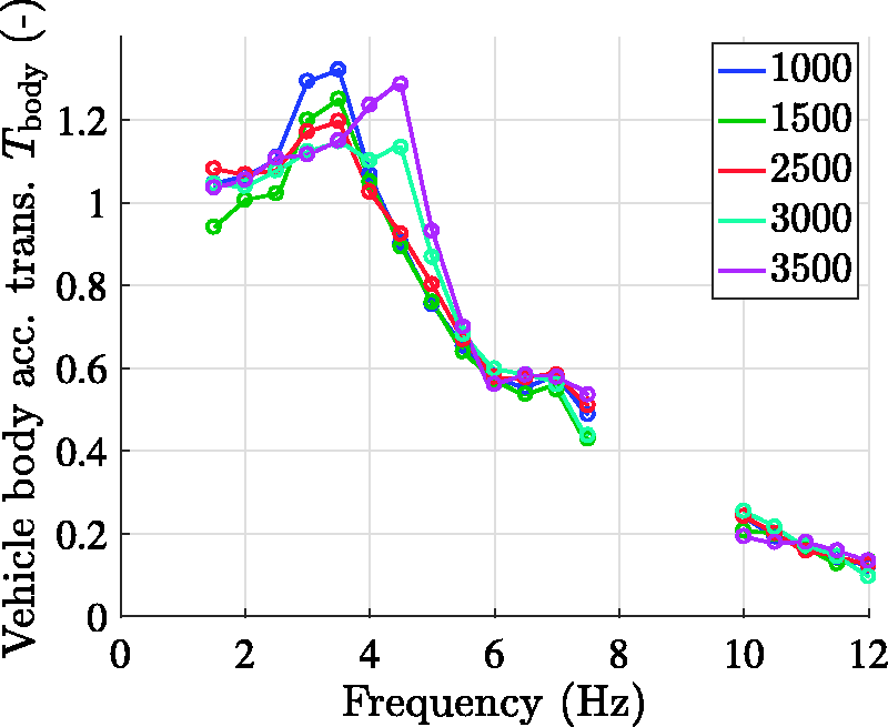
Vehicle body acceleration transmissibility evaluated for different parameters csh of the Skyhook control with the accelerometer-based relative velocity estimation.
Results of LVDT-based Skyhook control for five values of csh: 600, 750, 850, 1000, and 1250 are presented in Figure 10. Similarly to the previous case, these values were selected in order to present operation of the Skyhook control from the under-tuned to the over-tuned case. As before, an invariant point can be observed for the frequency equal to 3.5 Hz. It could be noticed that the best results were obtained for csh = 750, where the resonance peak is significantly decreased and quality of vibration mitigation is maintained.
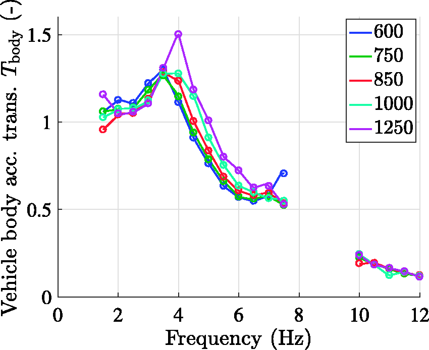
Vehicle body acceleration transmissibility evaluated for different parameters csh of the Skyhook control with the LVDT-based relative velocity estimation.
Results of the Skyhook control can be also compared taking into account the evaluated values of the ride comfort quality index listed in Table 4. The best instances of Acc-based and LVDT-based Skyhook control corresponding to csh = 1500 and csh = 750, respectively (bold text) confirm conclusions of the analysis carried out based on transmissibility characteristics.
Normalized ride comfort for the Skyhook control.
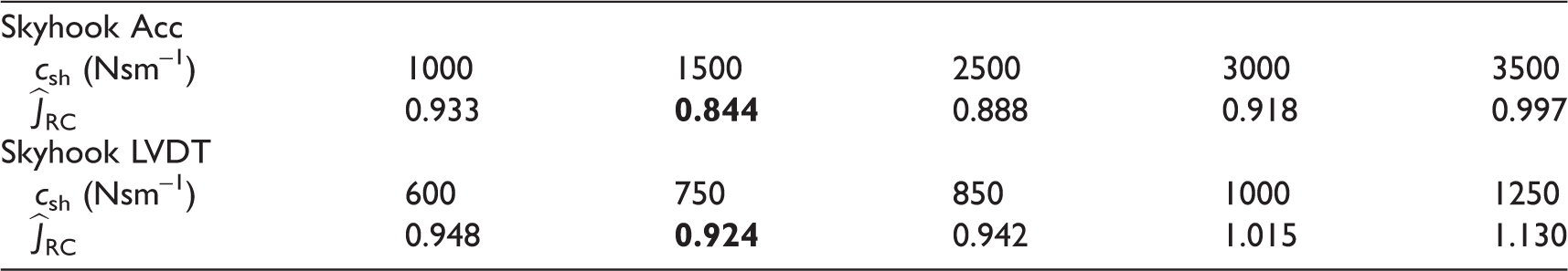
Note: The best index values are marked in bold.
Methods of PID tuning applied for MR dampers presented in the literature are based on optimization over the space of control parameters. Various optimization algorithms can be used for such a task, e.g. iterative learning algorithm applied in Talib and Darus 34 or particle swarm optimization algorithm used in Metered et al. 23 However, the proposed methods require performing consecutive experiments and evaluating values of the quality index for different combinations of control parameters, which is very time-consuming. Thus, in this study the solution space was directly analyzed while consecutive candidates and direction of the search were selected manually.
Experimental tuning of the PI algorithm was carried out in two stages. Since experiments performed for the Skyhook algorithm showed that application of the accelerometer based algorithm gave better results only this variant was tested for PI. First, vibration control was tested separately for the integral component ki within the range from 5000 to 60,000. In the case of the separate P component the range of kp was similar to the Skyhook since both algorithms are identical. Afterwards, experiments were carried out for different combinations of both components of the PI algorithm and the best set of parameters kp = 2000 and ki = 10,000 was marked.
All alternatives of Skyhook control were compared with each other and with the results obtained for the best case of the passive suspension with respect to the ride comfort issue. Plots of wheel and vehicle body acceleration transmissibility are presented in Figures 11 and 12. It can be stated that Acc-based Skyhook better mitigates vibration of the vehicle body, which is confirmed by vehicle body transmissibility characteristics and ride comfort quality index. It gives about 15% improvement of ride comfort quality index comparing to passive suspension, whereas the LVDT-based algorithm gives about 8% improvement.
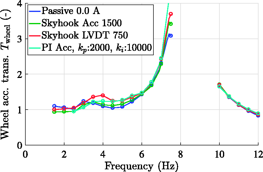
Wheel acceleration transmissibility evaluated for the best instances of Skyhook control with the accelerometer-based and LVDTs-based relative velocity estimation compared with the best instances of PI control.
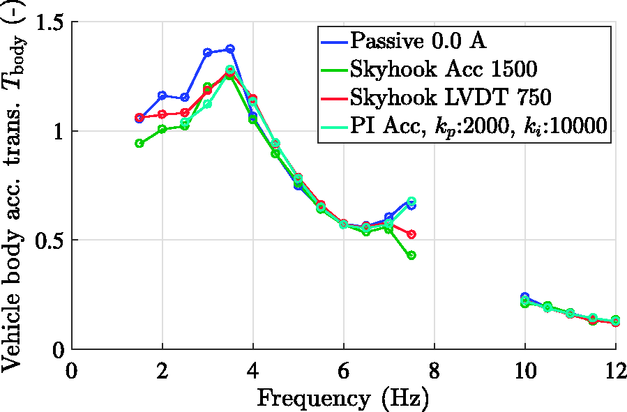
Vehicle body acceleration transmissibility evaluated for the best instances of Skyhook control with the accelerometer-based and LVDT-based relative velocity estimation compared with the best instances of PI control.
Results obtained for the best case of the PI algorithm presented in Figure 12 appears to be comparable to those offered by the Skyhook algorithm despite the search in a rather wide range and many combinations of the parameters. Thus, the Skyhook algorithm is more recommended in this case since it is more robust and less complex which is critical in real-time applications.
Groundhook control
Study of the Groundhook control is strictly related to road holding and the analysis is mainly based on wheels transmissibility and the road holding quality index. Similarly to the Skyhook control, parameters of the Groundhook algorithm cgh were the same for all quarters of the suspension system. Also, two alternatives of the relative velocity estimation were considered. Preliminary search for optimized control parameters indicated that in the case of the accelerometer-based Groundhook the best results of road holding can be obtained for cgh ranging from 1500 to 4500, whereas for the LVDT-based Groundhook the best results were obtained for cgh ranging from 1000 to 1500.
Transmissibility of the vehicle wheels is presented in Figure 13 for four values of cgh: 1500, 2500, 3500, and 4500 in accelerometer-based Groundook control. This gain factor was selected in order to show operation of the Groundhook control from under-tuned case (cgh = 1500) to a slightly over-tuned case (cgh = 4500). Similar to the results obtained for passive suspension, an invariant point of the wheel vibration can be noticed for the frequency equal to 6.5 Hz. Visual inspection of the wheel transmissibility suggests that the best results can be obtained for cgh = 3500, where quality of vibration mitigation is still maintained.
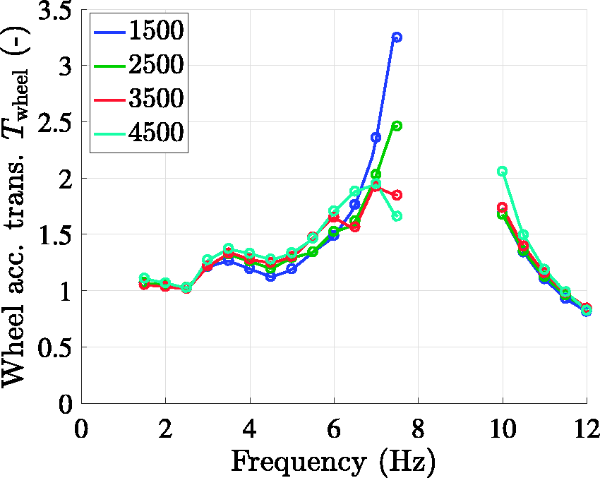
Wheel acceleration transmissibility evaluated for different parameters cgh of Groundhook control with the accelerometer-based relative velocity estimation.
Results of LVDT-based Groundhook control for four cases of cgh: 1000, 1250, 1350, and 1500 are presented in Figure 14. These parameters were also selected in order to present operation of the LVDT-based Groundhook from under-tuned to over-tuned case. An invariant point can be noticed for the frequency equal to 6.5 Hz, similarly as for Acc-based case. It could be noticed that the best results can be obtained for cgh = 1500, where the resonance peak is significantly decreased and quality of vibration mitigation is only slightly deteriorated for lower frequencies from 3.5 Hz to 6 Hz.
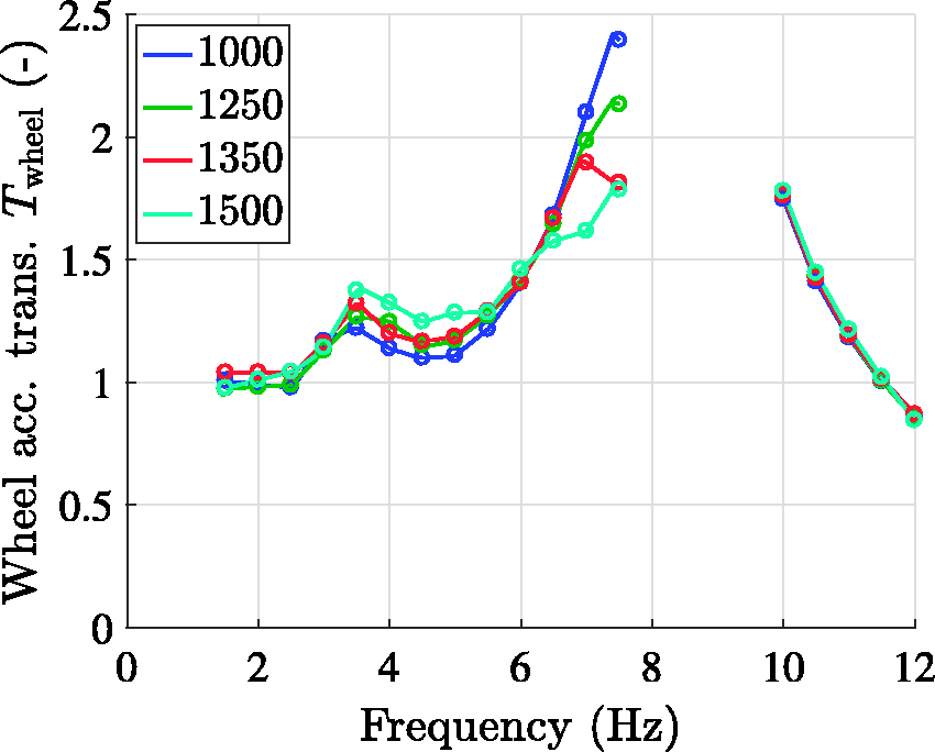
Wheel acceleration transmissibility evaluated for different parameters cgh of Groundhook control with the LVDT-based relative velocity estimation.
Results of Groundhook control can be also compared taking into account the evaluated values of the road holding quality index listed in Table 5. The best cases of the accelerometer-based and LVDT-based Groundhook corresponding to cgh = 3500 and cgh = 1500, respectively confirm conclusions of the analysis carried out based on transmissibility characteristics.
Normalized road holding for Groundhook control.
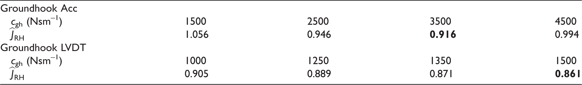
Note: The best index values are marked in bold.
Both alternatives of Groundhook control were also compared with each other and with the results obtained for the best case of passive suspension with respect to road holding issue, i.e. for imr = 0.07 A. Plots of wheel and vehicle body acceleration transmissibility are presented in Figures 15 and 16. It can be stated that LVDT-based Groundhook control gives the better results of mitigation of wheel vibration, contrary to Skyhook control, where Acc-based option offers better vibration mitigation. Higher efficiency of LVDT-based Groundhook control is confirmed by road holding quality index, as it gives about 14% improvement of road holding quality index comparing to passive suspension, whereas Acc-based algorithm gives about 8% improvement.
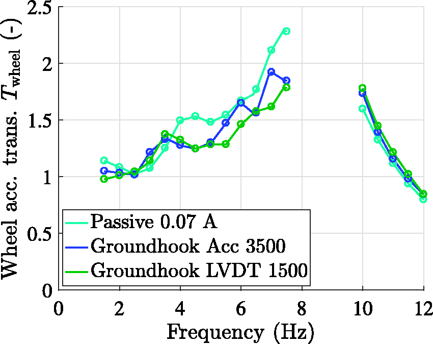
Wheel acceleration transmissibility evaluated for the best instances of Groundhook control with the accelerometer-based and LVDTs-based relative velocity estimation.
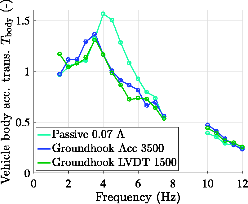
Vehicle body acceleration transmissibility evaluated for the best instances of Groundhook control with the accelerometer-based and LVDT-based relative velocity estimation.
Furthermore, the selected LVDT-based Groundhook control gives also better results of vehicle body vibration control as it is shown in Figure 16.
Discussion
Preliminary studies carried out by the authors in simulations suggested the Skyhook algorithm is resistant to over-tuning with high values of control parameters which in consequently suggests no need for the Skyhook tuning. However, experiments indicated inaccuracy of the current controllers used for the MR dampers, inconsistency between the real MR damper and its inverse model, as well as inaccuracy of the relative velocity estimation which are inevitable in reality. All these inaccuracies lead to the deterioration of the vibration control quality for higher frequencies of the road-induced excitation and for greater values of control parameters. It confirms that parameters of the algorithm controlling the semi-active suspension system should be tuned for a certain application.
Comparison of application of LVDT sensors and accelerometers reveals that the results obtained for LVDTs are worse what is probably due to the delay introduced by the applied measuring equipment. It gives another significant conclusion and suggests paying special attention to specification of the equipment. Additional simulation tests performed for the sinusoidal and wideband road-induced excitation confirmed that a slight delay in the measurement path has a more decisive influence on the control quality than significant measurement noise.
The presented work also showed results of mitigation of vehicle wheels vibration by using the well-known Groundhook algorithm. However, lower vibration of wheels results in larger tire deflection. It was noticed during experiments that higher parameters of the Groundhook correspond to more frequent loses of tire adhesion to the surface of mechanical exciters. Thus, from the road holding perspective a combination of the Groundhook with an algorithm related to the tire deflection would be more desired in the authors’ opinion.
Finally, the presented studies also refer to the problem of signal estimation in the road vehicles, which always exhibits finite accuracy. Herein, the absolute velocity and displacement of the selected vehicle part are estimated on the basis of the acceleration signal. The straightforward first-order digital filter was used for integration in order to minimize the time delay of such filter as well as selection of the filters’ parameters was crucial for the vibration control. A compromise always needs to be found since too large value of the filter time constant results in a long decaying of integration error while a smaller time constant and, consequently, the higher filter bandwidth results in a significant deterioration of the velocity and displacement estimation for the lower frequencies. Further research carried out in the field of the measurement signal preprocessing and estimation will be focused on sensor fusion methods.
Conclusions
The paper deals with the semi-active vibration control applied in the experimental off-road vehicle. The vehicle is equipped with numerous sensors, including the accelerometers located in the vehicle body and in the vicinity of wheels as well as the LVDT sensors, which measure deflection of each quarter of the suspension system. Original shock-absorbers of the vehicle were replaced with the MR dampers, which are used for vibration mitigation.
The original contribution of this paper consists in the presentation of the results obtained for the real object, particularly frequency characteristics of the tested layout. The main effort consisted in the evaluation of the acceleration transmissibility of the vehicle body and wheels, as well as the ride comfort and road holding indices determined for different settings of control algorithms. One of the most important issues was the synchronization of signals coming from different sensors and the implementation of algorithms in the embedded controller so that they work in real time with the appropriate sampling period.
For the purpose of this research, a typical vehicle diagnosis station including two mechanical exciters was adopted for experiments. Implementation of controllers related to the frequency of vibration exciters and to the in-phase excitation of the front right and left vehicle wheels enables the analysis of the vehicle response for different experimental instances.
Two semi-active control algorithms were tested, i.e. Skyhook and Groundhook, which are related to ride comfort and road holding issues, respectively. Besides, two different methods of estimation of the damper piston relative velocity were tested: using measurements obtained from accelerometers or from LVDT sensors. The vibration control algorithms were tested within the frequency range from 1.5 Hz to 12.0 Hz at intervals of 0.5 Hz, excluding the frequency range from 8.0 Hz to 9.5 Hz which was dangerous for the construction of the mechanical exciters.
It was demonstrated that properly tuned Skyhook and Groundhook control schemes improve the ride comfort or road holding quality indices by about 15%, compared to the passive suspension system with the uncontrolled MR dampers. Furthermore, it was stated that the accelerometer-based velocity estimation should be rather used in Skyhook control, whereas Groundhook control achieves better results with the LVDT-based estimation. Future research will be focused on methods of automatic tuning of classical vibration control algorithms, and then on adaptive semi-active control algorithms.
Footnotes
Acknowledgement
The authors would like to thank the Polish Division of Danfoss Group for delivering a frequency inverter for diagnostic experiments of the off-road vehicle.
Declaration of conflicting interests
The author(s) declared no potential conflicts of interest with respect to the research, authorship, and/or publication of this article.
Funding
The author(s) disclosed receipt of the following financial support for the research, authorship, and/or publication of this article: This study received partial financial support by the Polish Ministry of Science and Higher Education.