
Abstract
This paper describes the design, simulation, and performance evaluation of hybrid MR damper on quarter bus semi-active seat suspension coupled with human biodynamic model. Also, the whole body vibration (WBV) exposures were evaluated based on the international standard ISO 2631 (1997), and its parameters were used to measure the level of discomfort for bus drivers. The hybrid MR damper was proposed to enhance the damping force within low current supplied and achieve a fail-soft capability in case of electrical failure. The characteristics of the proposed hybrid MR damper were compared to the conventional MR damper by considering the same size, materials, and current input. The designed damper was incorporated to seat suspension system coupled with biodynamic lumped model, and the governing equations of motion of the full model were derived. Skyhook controller was used to control the amount of current to be supplied to hybrid MR damper. The controlled semi-active hybrid MR and conventional MR seat suspension are compared to uncontrolled system for two types of road excitation. The simulated results show that the driver seat comfort was improved by the skyhook controller than the uncontrolled case. The evaluated WBV showed that the hybrid MR damper can improve the driver life from fairly uncomfortable to little discomfort.
Keywords
Introduction
Driver’s fatigue and lower back pain are the common issues related to ride discomfort. The source of discomfort is mostly caused by the vibration from the road roughness which is transmitted to the driver seat. Most of researchers have revealed that professional bus drivers are prone to low back pain (LBP) than others. 1 To know how the vibration affects the driver’s health, there are a lot of research studies concerning whole body vibration (WBV) exposure for professional drivers. Thamsuwan et al. 2 conducted a comparison study of measuring the WBV exposure in high floor coach and low floor city bus. They have found that the seats only attenuate 10% of the transmitted vibration and attenuate it on the speed humps. Okunribido et al. 3 conducted a study about city bus driving and LBP and they have found that the city bus drivers spent more than 60% of their work time driving. To reduce the vibration risks for the health of the drivers, different techniques were developed to improve the driver seat comfort. Tengler et al. 4 proposed an optimal springing o f a seat for driver comfort improvement. In their work, they were aiming to calibrate the existing system and an improvement of 58% and 68% was achieved for smooth bump and sharp bump, respectively. All the above authors were focused on improving ride comfort either by optimizing or introducing active system to the existing passive model. However, all the models have the benefits and drawback. Passive system which is equipped by spring, shock absorber and sometime stoppers is well known for their reliability and low cost but has poor rider comfort and limited operational range. On the other hand, active suspension system which uses actuators to generate force was provided to improve the ride comfort significantly. However, its higher cost and extra space requirement for the system has been a challenge for the car manufacturers. 5 To overcome the higher cost of active suspension and keep harnessing the reliability and easiness of passive suspension, a semi-active suspension was introduced. Unlike actuators, magnetorheological (MR) damper is commonly used as semi-active device. A lot of works about semi-active suspension were conducted and different equipment featuring MR dampers are already available at the market. 6 Currently, semi-active MR damper is still a hot topic due to its fast response time, controllable damping force, and lower energy consumption compared to active system. 7 Du et al. 8 proposed a semi-active control for full car with seat suspension and driver body using ER damper, and their results showed that semi-active control can provide better ride comfort than passive. Metered and sika9,10 presented a vibration control of semi-active seat suspension using fuzzy logic to control MR damper force.
To contribute in this study, a hybrid MR fluid damper for seat suspension is proposed. Unlike the conventional MR damper, this model incorporates a permanent magnet (PM) which helps to enhance the yield stress of MR fluid and keep the activeness of hybrid MR damper in case electrical circuit failure. Also, the hybrid MR damper is evaluated under eight DOF of quarter bus coupled with human biodynamic model to show its effectiveness on vibration isolation. The results presented in this work are obtained through computer simulation due to the time consuming, cost and much effort required to conduct experimental work. The rest of this paper is organized as follows: in section Modeling of hybrid MR damper, hybrid MR damper is modeled; section Seat suspension system, biodynamic lumped model coupled with quarter bus model is developed; section Simulation results and discussions is for Simulation results and evaluation; and section Whole body vibration analysis is for conclusion.
Modeling of hybrid MR damper
Generally, the conventional MR dampers generate low damping force in off-state condition.
11
The damping force is increased as the current is supplied to the electromagnetic coil. However, in case of electric circuit failure, the MR damper retains the behavior of passive damper which also called fail-soft. The hybrid MR damper is composed by two PMs apart from electromagnetic coil. In off-state condition, the two PMs will generate low magnetic field in the annular gap. In the on-state condition, the electromagnetic coil will also generate enough magnetic field depend on the supplied current and these magnetic field will be added to the initial one generated by PM to form the total magnetic field in the damper valve. The use of hard magnets in our model help to overcome the fail-soft issue when the smaller current is supplied to the coil. The size of hard magnet should be carefully selected as it can lead to fail-hard also called higher initial damping force which is not beneficial to our application. Figure 1 shows a full schematic configuration of the proposed hybrid MR seat damper and structural dimension which are also presented. Figure 2 represents the cross section of piston valve of the proposed hybrid MR seat damper. Where part 1 is core, 2 is PM, 3 is coil, 4 is coil insulator, 5 is piston rod, 6 is flux return, 7 is bottom pole, 8 is upper pole, and 9 is piston outer seal. Schematic configuration of hybrid magnetorheological damper. Structural configuration of piston valve for hybrid magnetorheological damper.
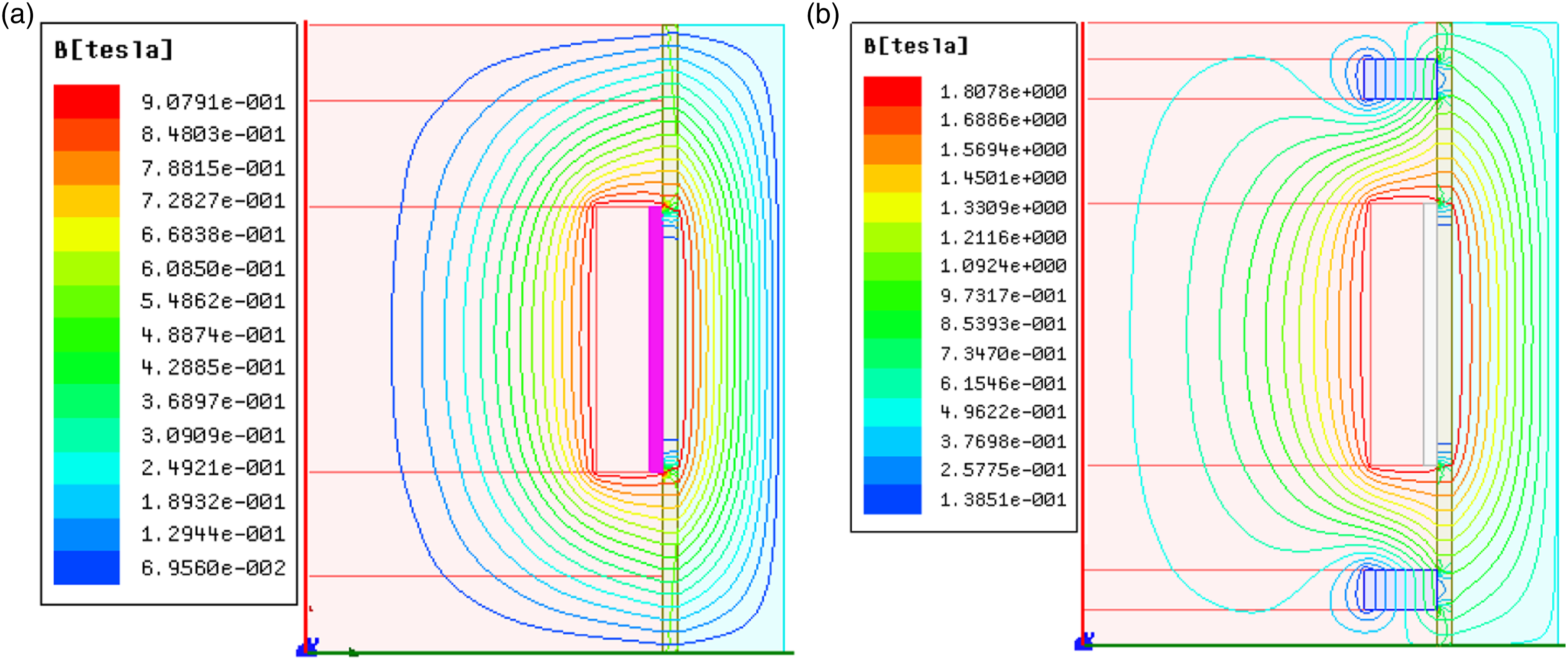
Due to the nonlinearity of the magnetic materials which compose the piston valve, it is difficult to measure analytically the magnetic induction and yield stress of MR fluid in the annular gap. The finite element analysis using ASNYS MAXWELL software was used to simulate and estimate the magnetic flux density and field intensity respect to various current input. Figure 3 shows a 2D symmetric model for hybrid MR valve and it shows how the magnetic flux pass through the annular gap for both magnets and primary coil. All the dimensions for hybrid MR piston valve are mentioned in Table 1. Figure 4 shows the distribution of magnitude field lines and magnetic flux density from both conventional and hybrid MR dampers. The physical properties of MR fluid (MRF-132DG) from LORD Corp was taken as controllable fluid for our damper. According to Ref. 7, the yield stress induced by input current in annular gap is obtained as follows Magnetic circuit of hybrid type magnetorheological damper. Dimensions for proposed hybrid MR. Note: MR: magnetorheological. Finite element analysis result of piston core in MR damper. (a) Conventional MR damper and (b) hybrid MR damper. Note: MR: magnetorheological.


For
By neglecting the effect of gas compliance and friction force, the total damping force for the proposed hybrid MR damper is derived as follows
From equation (6), it is clearly seen that the damping force is composed by two parts. Part one is related to fluid viscosity of MR fluid and the structure of hybrid MR damper; it is also called viscous damping force. On the hand, there is damping force which is related to yield stress of MR fluid in on-state condition and it varies with the magnetic field strength induced. The controlled force is also called Coulomb damping force. 14
Figure 5(a) and (b) illustrates the simulation results of damping force against piston velocity at various magnetic fields obtained from both conventional and hybrid MR damper, respectively. As shown in Figure 5(a), at the off-state condition ( Damping characteristics of conventional MR and Hybrid MR seat damper. (a) Conventional MR damper and (b) hybrid MR damper. Note: MR: magnetorheological.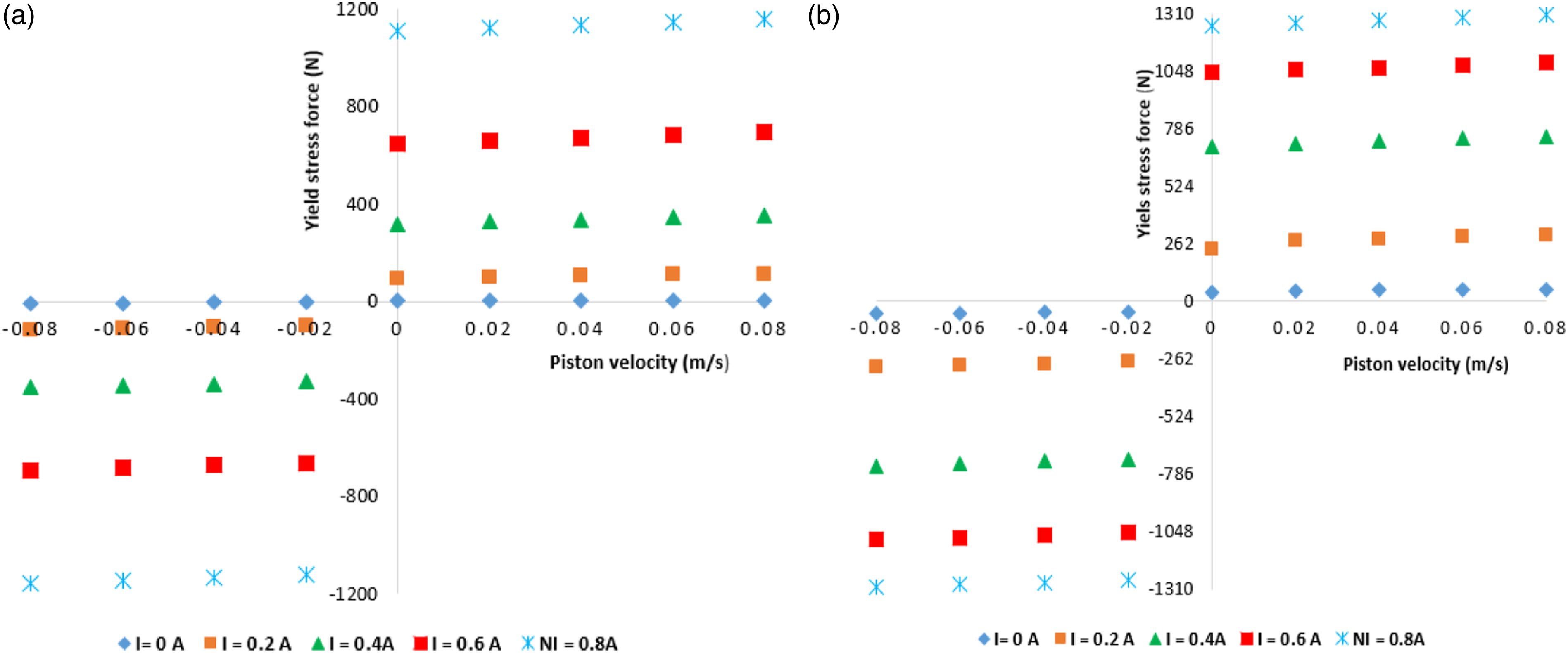
Seat suspension system
Since a decade ago, different constructions from lower to higher degree of freedoms (DOFs) for seat suspension have been proposed. Metered et al.
15
proposed a single DOF for seat suspension. A simplest form with 4 DOF was proposed by Gündoğdu.
16
Also higher degrees of freedom for seat coupled with human model were presented by Refs 17 and 18. Since we will deal with the WBV for bus driver, we preferred to work with a model of eight DOF as shown at Figure 6, where 4 DOF are for human model, two DOF for seat system and two DOF for quarter bus model. Quarter bus seat suspension coupled with biodynamic lumped model.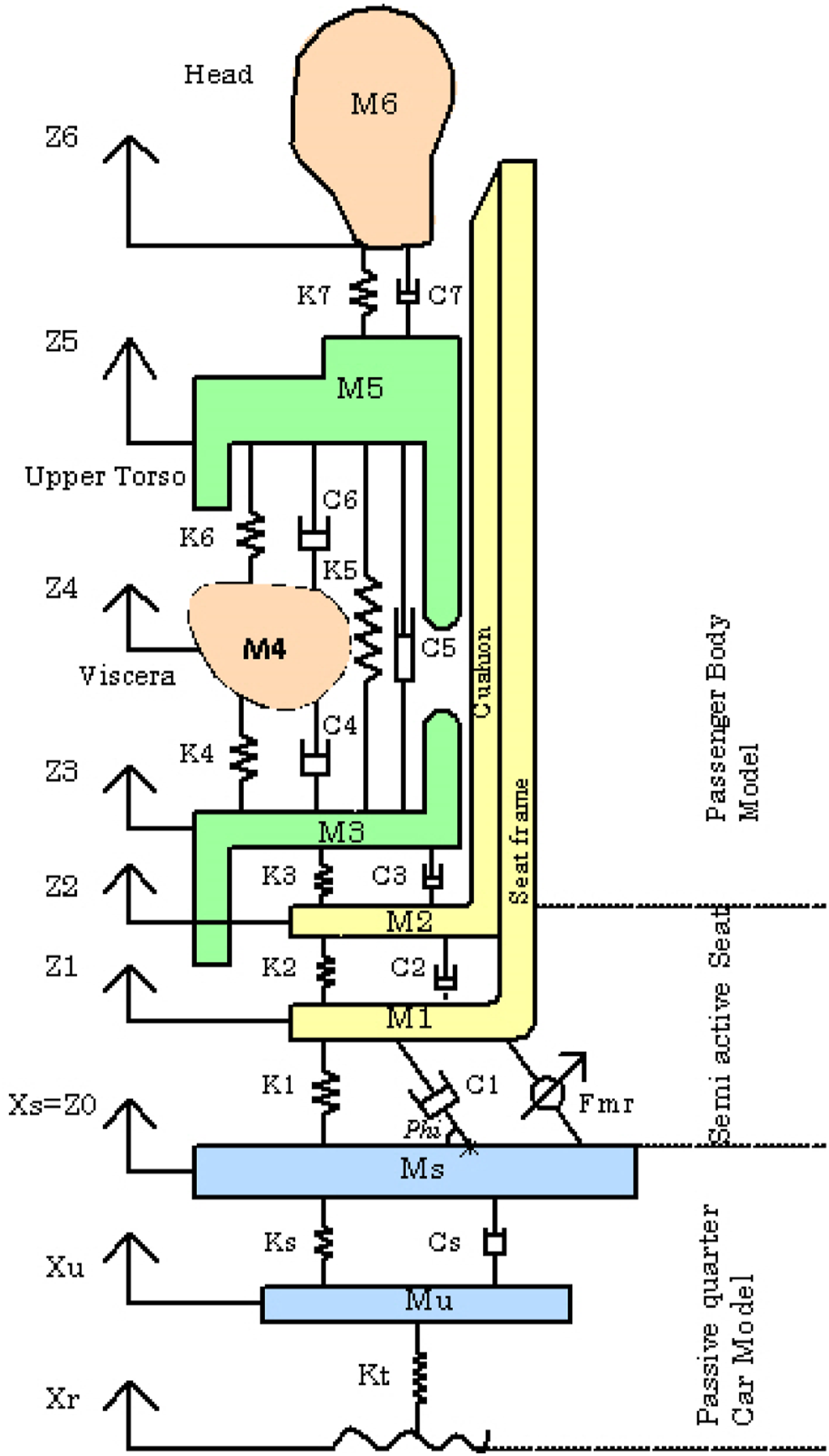
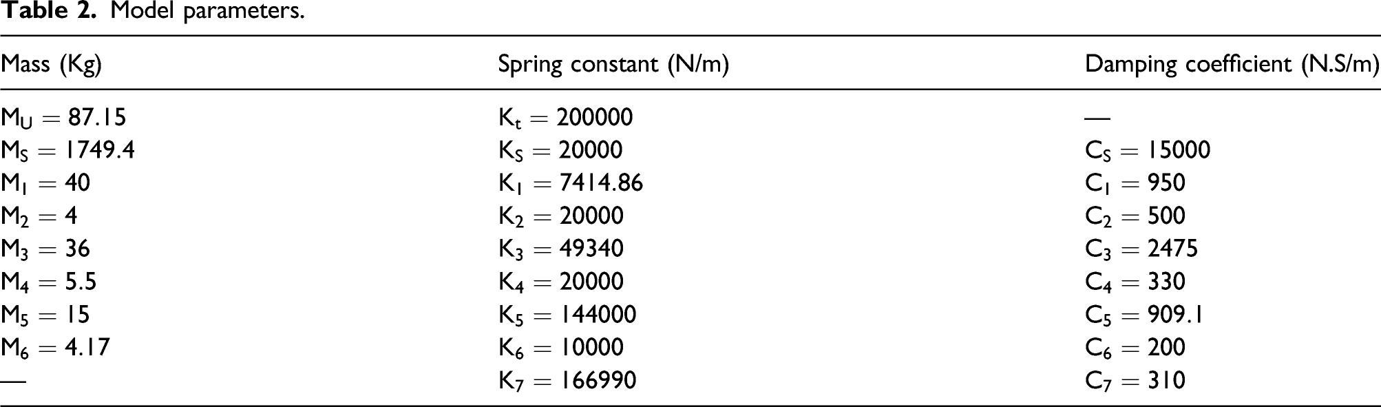
Model parameters.
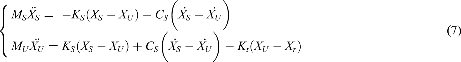
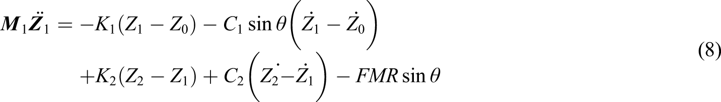
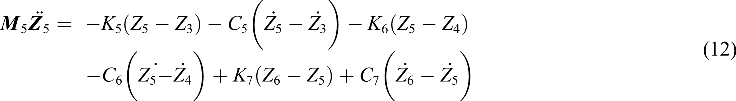
The dynamic model equations for the system are described below from their static equilibrium state:


To control the vertical vibration responses, skyhook controller is chosen for its simplest and easy implementation. Moreover, this type of controller has proven to be powerful in terms of suppressing the vertical vibration and improving ride performance.7,19,20 The ideal skyhook controller is approximated by the following control logic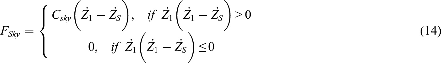
Once the control output 
Simulation results and discussions
All the results presented in this paper were simulated via MATLAB/Simulink software, and both uncontrolled and controlled results are compared. To assess the ride comfort of the driver, the displacement of seat, head, and their respective accelerations are provided. During simulation, two types of road excitation, bump and random roads were used. In this work, the input disturbance to the seat system is taken as
bump road excitation.
9
In this case, the pavement profile road 
random road excitation
22
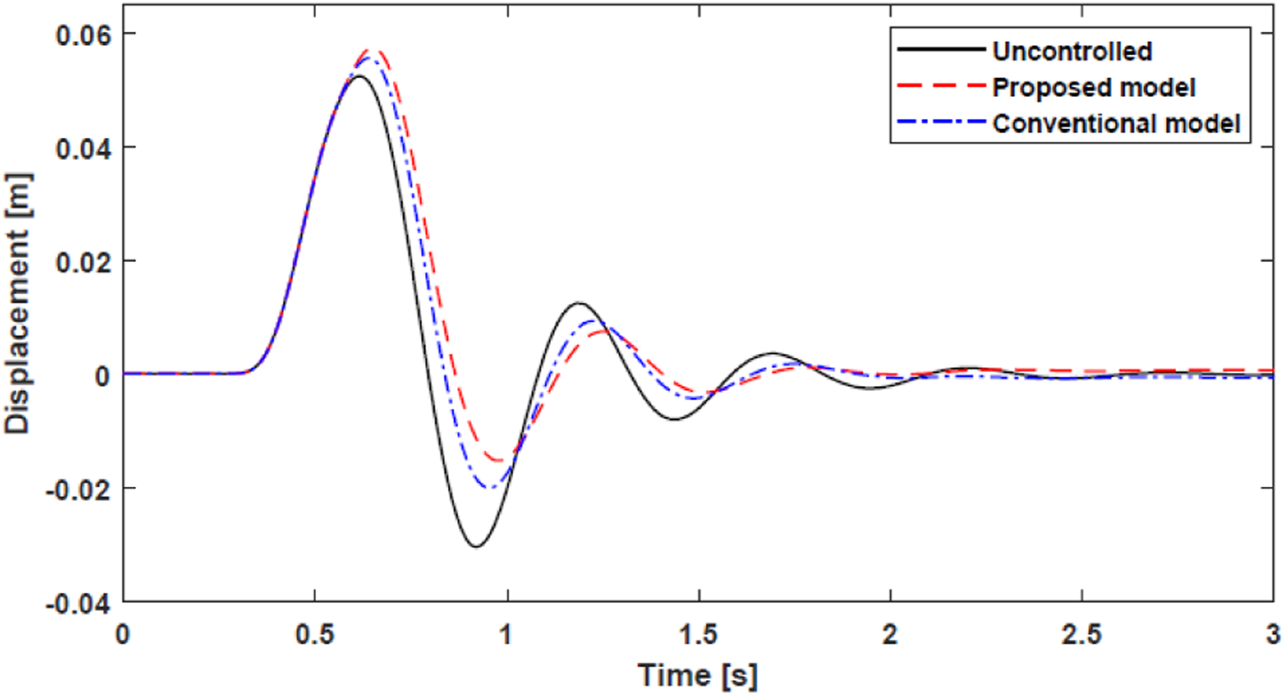
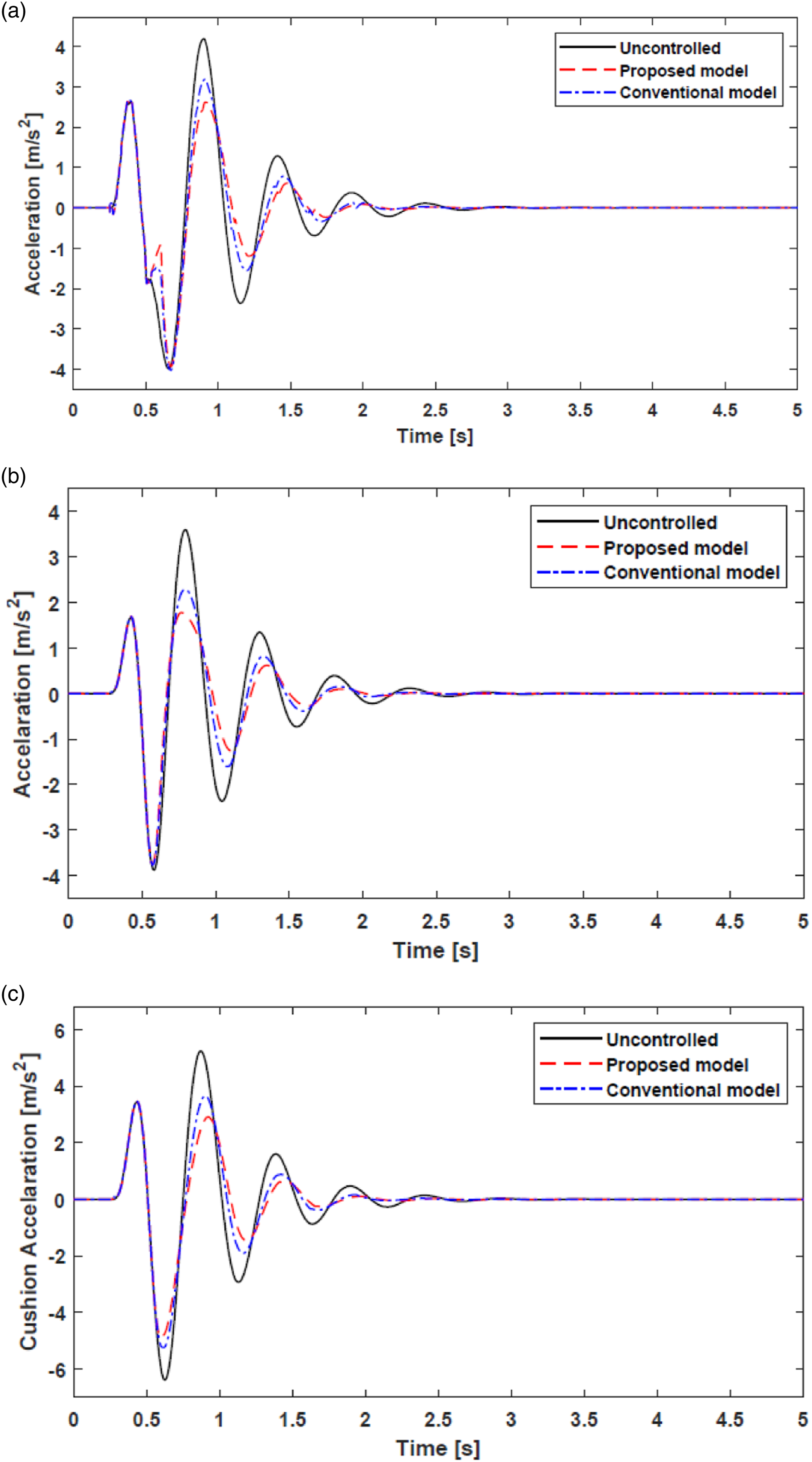
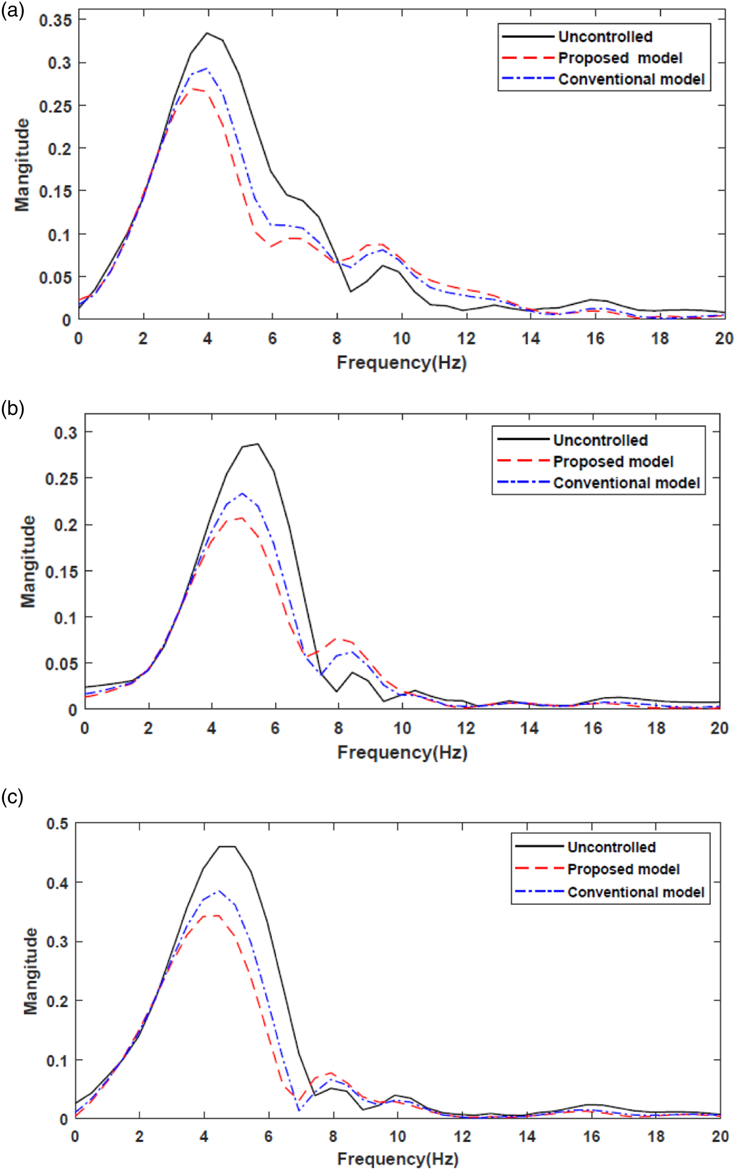
In this case, the pavement profile road The bump response for seat displacement is shown in Figure 7, by comparing peak to peak values, and the controlled responses for both proposed and conventional models are slightly high compared to uncontrolled response. However, they have a fast settling time. This might be caused by displacement of sprung mass which was taken as input to seat system. Also, the proposed model seems to amplify the output displacement response than conventional MR damper. On the other hand, the skyhook controller has managed to suppress all the unpleasant vibration supplied to the driver seat. Figure 8(a) and (b) show the acceleration response for seat frame and driver head acceleration, and it is clearly seen that the proposed model has performed well than the conventional MR damper and uncontrolled responses in terms of both peak to peak values and RMS values. Figure 8(c) represents acceleration response for seat cushion, and it is also shown that the controlled response by skyhook controller for proposed model is better than that of conventional MR damper and uncontrolled one. Seat frame displacement. (a) Seat frame, (b) driver head, and (c) seat cushion. Acceleration responses in time domain for bump road. RMS value and Percentage improvement for bump road. Acceleration responses in frequency domain for bump road. (a) Seat frame, (b) driver head, and (c) seat cushion.
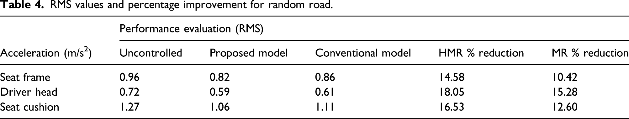
For the case of random vibration, the acceleration and frequency domain for uncontrolled, HMR, and MR controlled responses were illustrated in Figures 10 and 11, respectively. In this case also, the controlled hybrid MR damper outperformed well the conventional MR damper in terms of both attenuate the vibration and minimize the energy transferred to the seat frame and driver body. For better visualization of how all responses performed, the RMS values and percentage reduction for accelerations were calculated and presented in Table 4. The controlled MR damper has reduced the RMS by 10.42% for seat frame, 15.28% for driver head, and 12.6% for seat cushion compared to uncontrolled responses. On the other hand, the controlled HMR damper compared to uncontrolled responses has managed to reduce the RMS by 14.58% for seat frame, 18.05% for driver head, and 16.53% for seat cushion. Figure 11 shows the frequency domain for acceleration responses and they revealed that the highest peaks occur around the frequency of 2 Hz and diminished around 3.8 Hz. The frequency domain results clearly show that the controlled hybrid MR damper responses attenuate the peak acceleration better than conventional MR damper.
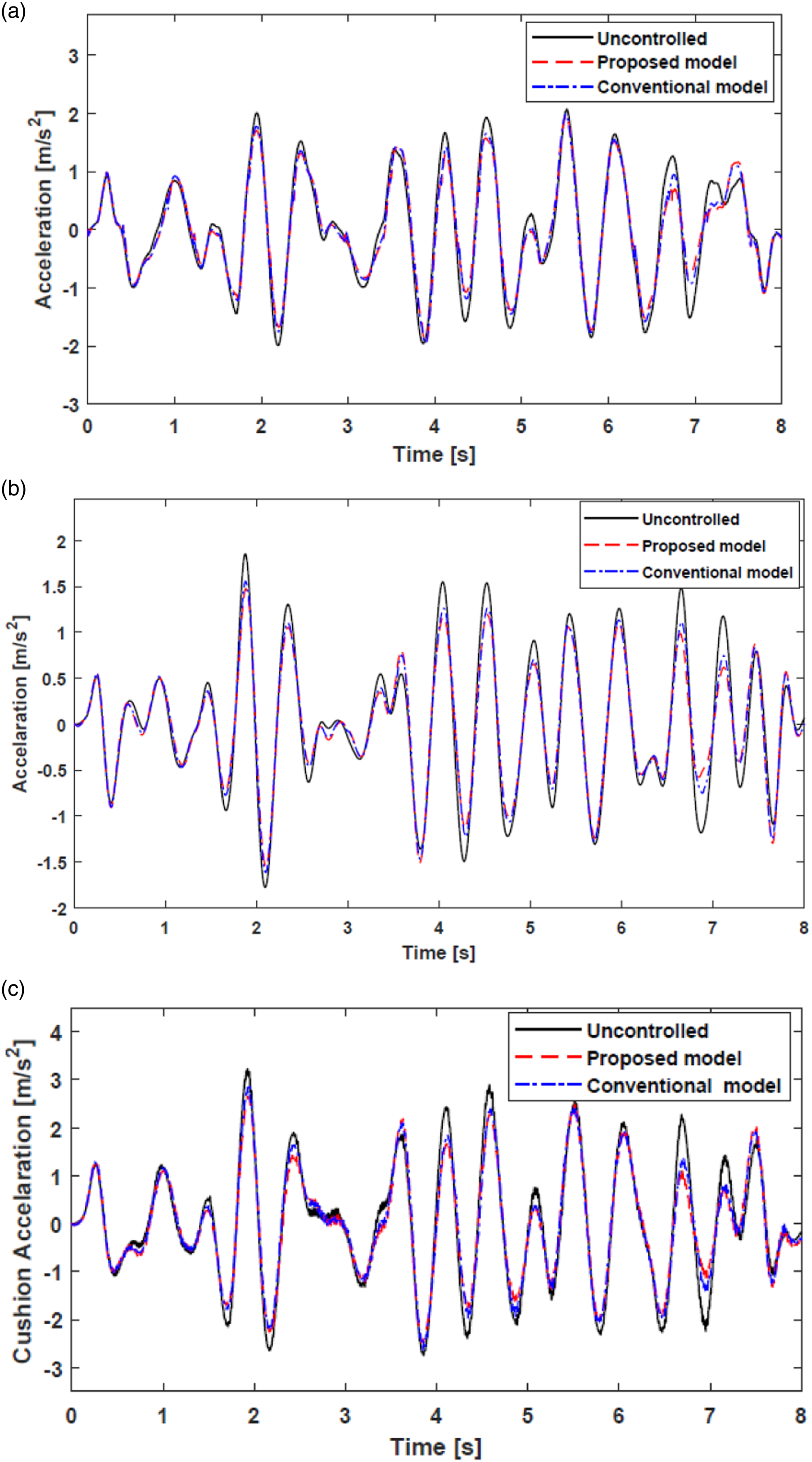
Accelerations responses in time domain for random road. (a) Seat frame, (b) driver head, and (c) seat cushion.
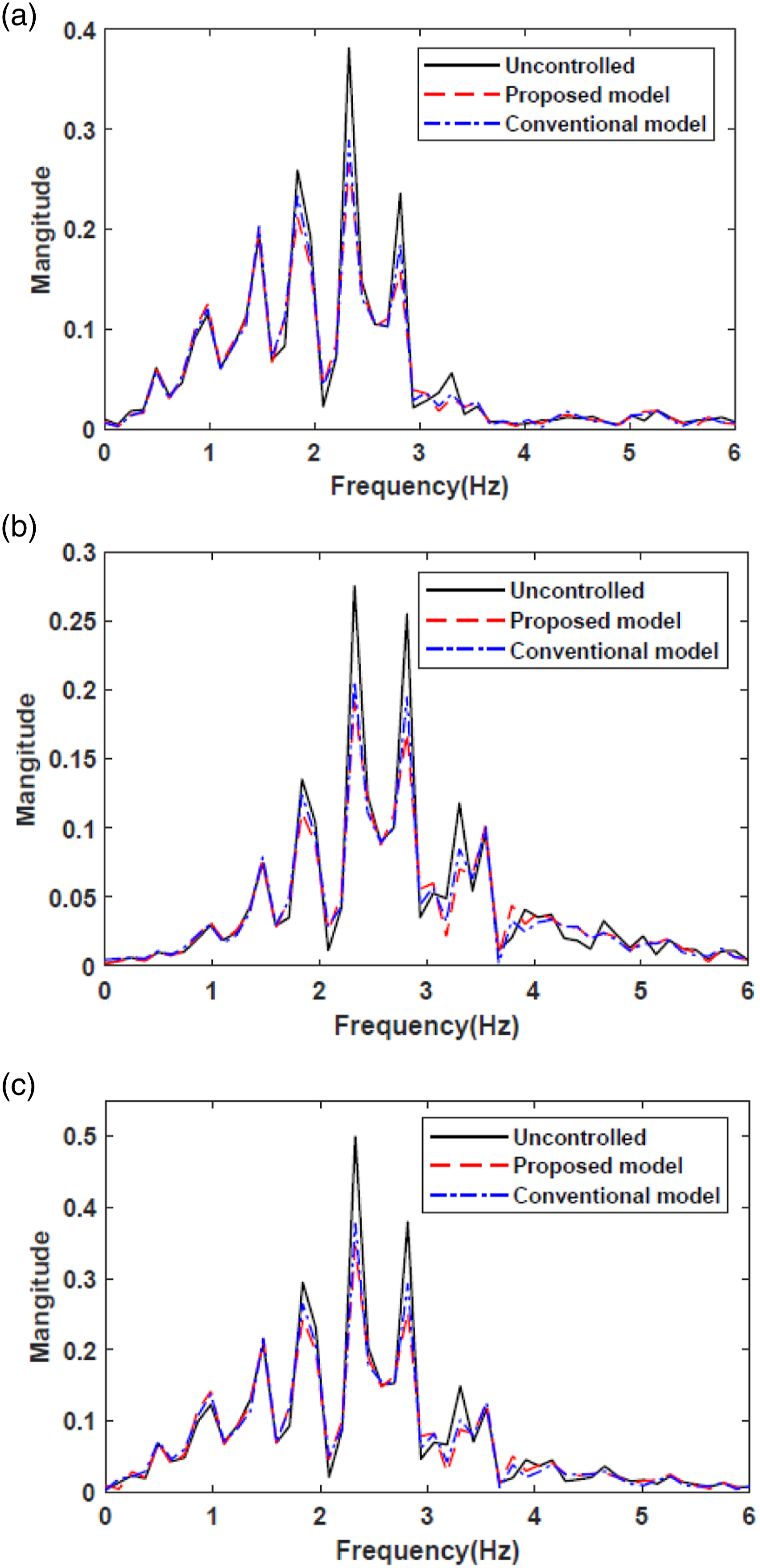
Accelerations responses in frequency domain for random road. (a) Seat frame, (b) driver head, and (c) seat cushion.
RMS values and percentage improvement for random road.
Whole body vibration analysis
To evaluate the driver body exposure to vibration and how bad those vibrations might affect driver health, ISO 2631
23
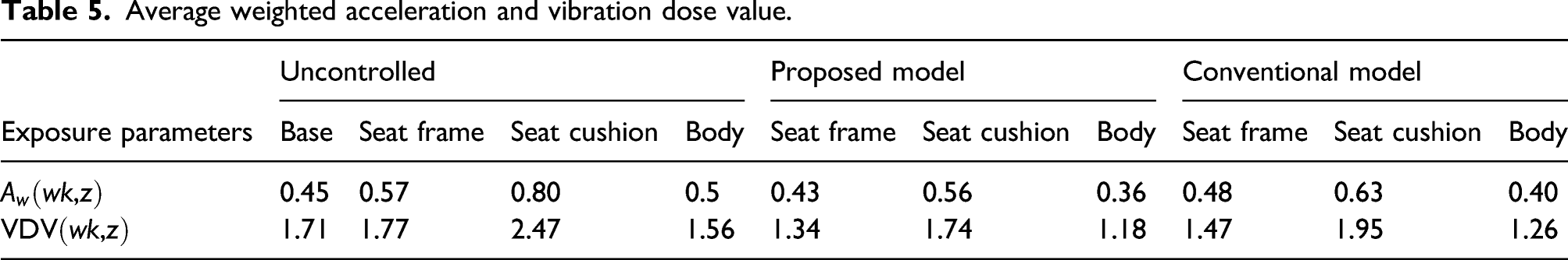
(International standard for evaluating human exposure to WBV) is applied to evaluate the vertical motion of seat suspension. The whole body exposure parameters evaluated are as follows: weighted RMS acceleration 


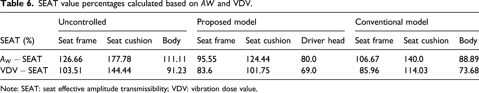
When the value of SEAT is greater than 100%, this indicates that the seat is amplifying vibration. However, if the SEAT is less than 100%, the SEAT is attenuating vibration. To compute the exposure parameter values, we only considered vertical motion for our quarter bus model. The calculated values for evaluated WBV for both controlled proposed model and conventional model were compared to uncontrolled responses in Figure 12. It shows the WBV performance of the three parameters for driver head, seat frame, and seat cushion acceleration. The controlled values are labeled in brown and orange colors for conventional and proposed models, respectively. The uncontrolled one is labeled in blue color. It is clearly seen that the proposed model values for weighted acceleration (Aw) have significantly reduced by 24.6%, 28%, and 34.9% for seat frame, driver head, and seat cushion acceleration, while the conventional MR model suppresses the vibrations by 5.8%, 20%, and 21.25% for seat frame, driver head, and seat cushion, respectively. The SEAT values were calculated from both obtained Aw and Comparison of whole body vibration performances. (a) Driver head, (b) seat frame, and (c) seat cushion. Average weighted acceleration and vibration dose value. SEAT value percentages calculated based on Note: SEAT: seat effective amplitude transmissibility; VDV: vibration dose value. Scale of discomfort suggested by ISO 2631.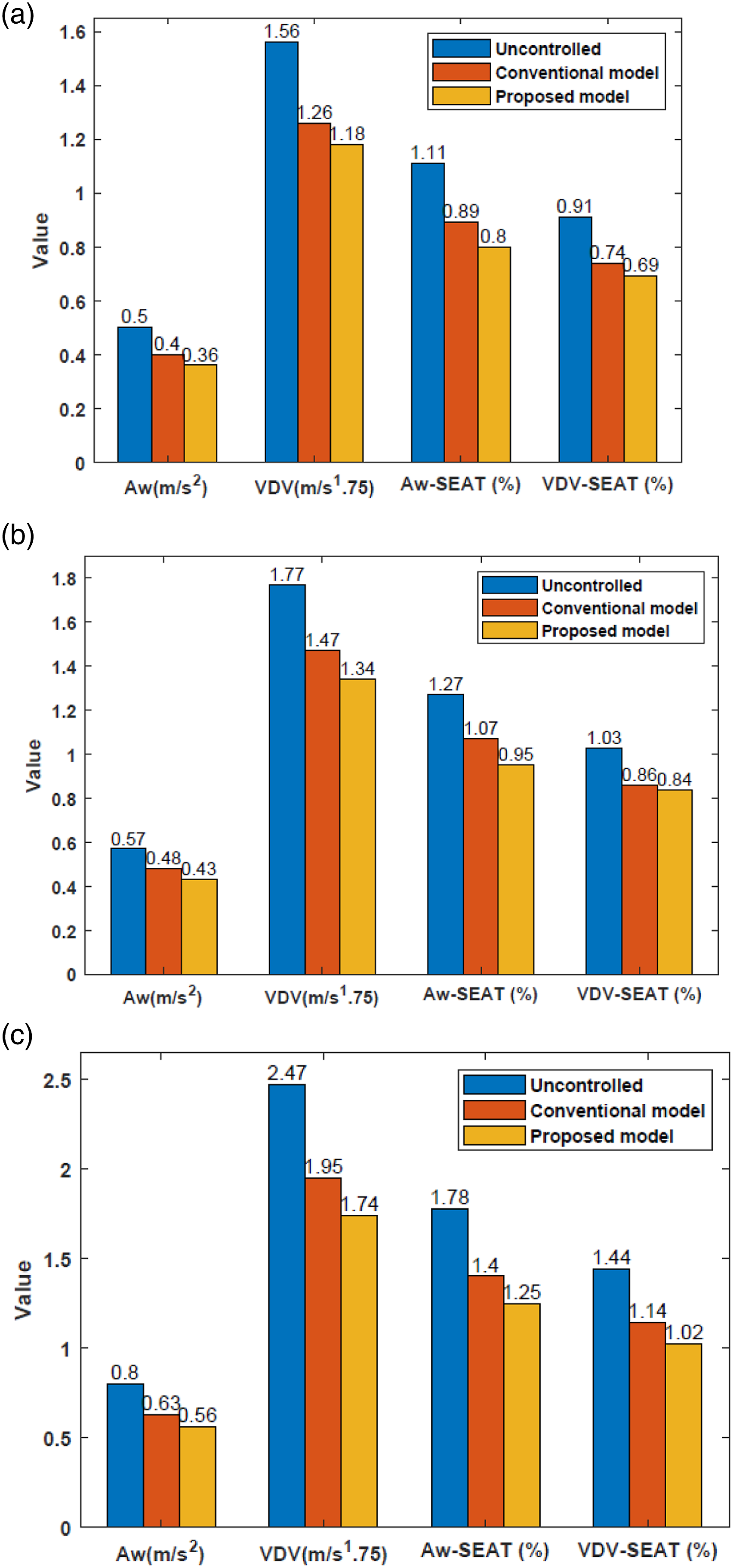
Conclusion
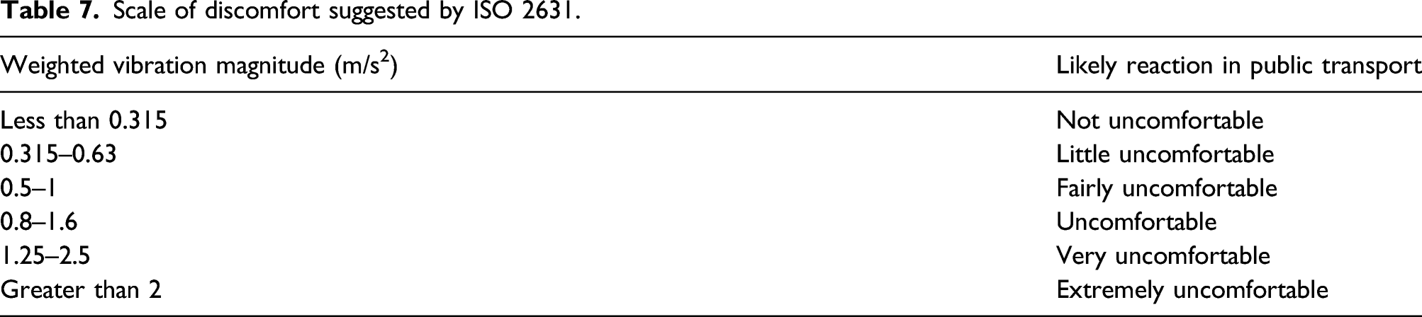
In this work, the hybrid MR damper for vehicle seat suspension was proposed, and its effectiveness was compared to conventional MR damper through MATLAB software. At higher current of 1A, the damping force obtained was higher in hybrid MR damper than in conventional one. Semi-active seat for ¼ bus coupled with human model featuring hybrid MR damper was modeled and skyhook controller was used to control the vertical vibration of the system. For the case of bump input road, the HMR damper was proven to be effective than conventional MR damper. Similarly, to the case of random road, the hybrid MR damper outperformed the conventional MR damper in terms of suppressing the unwanted vibrations. Also, for both cases of controlled HMR and MR responses, there was a great improvement in ride comfort than in uncontrolled responses for both bumpy and random roads. To ensure that the vibrations exposed to the driver are not harmful, the WBV parameters were calculated and the little discomfort to the driver was confirmed based on the discomfort chart by ISO 2631 (1997). SEAT values revealed that the uncontrolled system amplifies the acceleration, while the skyhook controller attenuates the acceleration responses.
Footnotes
Declaration of conflicting interests
The author(s) declared no potential conflicts of interest with respect to the research, authorship, and/or publication of this article.
Funding
The author(s) disclosed receipt of the following financial support for the research, authorship, and/or publication of this article: This research was supported by the MSIT (Ministry of Science and ICT), Korea, under the Grand Information Technology Research Center support program (IITP-2021-2020-0-01612) supervised by the IITP (Institute for Information & communications Technology Planning & Evaluation). This research was also supported by Basic Science Research Program through the National Research Foundation of Korea (NRF) funded by the Ministry of Education (No. 2020R1I1A3074547).