
Abstract
The control of vibration and displacement in structures under seismic excitation is very challenging, and designing a structural control system against disturbances has drawn great attention. This paper concentrates on implementing the bees algorithm to tune gains of traditional PID controller for active vibration control of a building-like structure with two floors under Northridge Earthquake excitation. Bees algorithm is a diverse method to ensure an efficient solution for optimisation of a controller according to customary trial-error design methods. The main aim of this study is optimisation of KP, KI and KD gains with bees algorithm in order to obtain a more effective PID controller to suppress vibrations of the floors during the earthquake excitation. After definition of the system and bees algorithm, PID controller offline tuned with bees algorithm using mathematical model of system. Moreover, the aim is to compare the performances of the BA with an existing optimisation method, genetic algorithm (GA), implemented on the system. The paper presents the experimental results that were obtained from the structure system to show the efficiency of the tuned PID controller. As a result, the performance and effectiveness of the tuned PID controller are investigated and verified experimentally. The displacements and accelerations of the floors and the cart are decreased considerably. The experimental responses of the system are given in graphical form.
Introduction
A lot of investigations focus on the influences and critical threats of natural disasters like earthquakes over structures. Structural control systems include active mass dampers that are used to suppress unexpected disturbances in tall buildings and, moreover, to protect from strong winds. Experimental studies are needed to vibration control of structures under seismic warning because of it is vital trouble for humanity. In the past decade, a variety of control strategies had been used and useful applications are accomplished to suppress vibrations of the structure under unstable excitation. In general, Seismic defensive systems consist of three categories: passive control systems, semi-active control systems and active control systems. Using external force is a necessary feature of active control to effect the control action of systems. Some studies have shown that active devices which are designed as a damper to influence of vibration modes are capable of decreasing vibration of structures.1–5 Because the response can be influenced by natural modes, active mode control is very suitable for multi degree of freedom (MDOF) structures. An external power source does not require passive control of systems and they are more cost-effective and effortless in engineering applications. The performance of the active control is excellent compared to the passive control in diminishing the vibration of structure. Passive control methods are chiefly divided into two parts: absorption and dissipation. Furthermore, passive control may be added to an active control scheme to reduce its energy requirements.
Two-floor structure vibration can be generally controlled in two ways: active control and passive control. In the passive control, passive mass damper modifies the structure response without using an external power supply. The passive mass damper reduces the vibration response of a structure without using any control force. As the passive dampers cannot adapt to the structure response changes, it cannot assure successful deflection suppression. In the active control, active mass damper can generate required forces for controlling the structure dynamics. Active actuators can generate the required forces for controlling the structure dynamics. Using an external power supply, active mass damper will modify the structure damping, which results in a structural dynamics change.
Xu and Ko 6 studied that dynamic response of damper-connected adjoining buildings under earthquake excitation. Mahmoud et al. 7 examined that optimal control of seismically excited building structures. An optimal control is applied to the structure and the simulations results are given to show the advantages of the control type. Yamada and Kobori 8 introduced fundamental dynamic and control strategies and they studied the influence of feedback and feed forward control rules. Li et al. 9 established the model of multiplex structures under earthquake or wind force and they put forward open and closed-loop control rules to structural control. Yağız et al. 10 designed the second-order LQR controller to avoid earthquake and wind vibration of actual structure model which have MDOF with active mass damper system. Zhu et al. 11 examined the interaction of parallel structures to decrease the impact of seismic excitation. Meirovitch and Stemple 12 improved the modelling of distributed structures to control.
Akhiev et al. 13 proposed a performance index for active control of structures under earthquake and implemented the optimal control of structure. Mei et al. 14 gave a general formulation of model predictive control (MPC) based on acceleration feedback of structures under earthquake impact. MPC is employed to control of structure that has active mass damper and then represent perform of MPC. Özer et al. 15 studied about sliding mode control of building model and they optimised the proposed controller by using genetic algorithm. Semi-active vibration control of structure is investigated by Pastia. 16
Casciati et al. 17 using real-time wireless sensors, carried out structural control with active mass damper. Stewart et al. 18 and Arrigan et al. 19 studied the semi-active and active vibration control of wind turbines with tuned mass damper. Pisal et al. 20 investigated the dynamic response of structure with semi-active tuned mass friction damper. Energy harvesting and vibration control of structures were considered by Tang. 21 Scheller et al. 22 considered versatile active mass damper to oscillation control of proposed structure. Vibration control of three-dimensional structure was researched by Yanık. 23 Park et al. 24 developed modal-space reference tracking fuzzy controller for structure against earthquake. Hudson et al. 25 and Lu et al. 26 investigated active vibration control of real structures to demonstrate the effectiveness of the proposed control methods.
Boz et al. 27 present a numerical and experimental study on active vibration of control system. A model based on optimal velocity feedback controller is used as control algorithm. Julai and Tokhi 28 studied the development of an active vibration control system with distributed disturbances using genetic algorithms, particle swarm optimisation, and ant colony optimisation. Xua et al. 29 introduce a synthetic optimisation analysis method of structures with viscoelastic dampers, namely the simplex method. The optimal parameters and location of viscoelastic dampers can be determined by this method. Xua et al. 30 proposed the Bingham model of magnetorheological damper, and the formula relating the yielding shear stress and the control current of magnetorheological dampers was put forward that matches with the experimental data.
In this study, the deflection control of a two-floor building-like structure system under scaled Northridge Earthquake is performed experimentally by using active mass damping system. The suggested structure consists of two floors, and a cart as active mass damping (AMD-2) that is mounted on the second floor is used to overcome of horizontal deflections. The acceleration effect of scaled earthquake is created by a shake table under the structure. PID controller ensures the deflection control of the floors within pre-determined deflection criteria by controlling the cart. The optimum KP, KI and KD gain parameters of PID controller are determined by tuned with the bees algorithm and genetic algorithm to provide the minimum deflection of the floors under Northridge.
This paper presents tuning of PID controller for a two-floor structure using a swarm intelligence-based metaheuristic algorithm and it differs from the other works in the literature with its technical feature. PID controller gains are crucial to suppress deflection of floors but they are generally determined using customary methods such as trial and error method and auto-tuning. In order to contribute to the literature and develop a different methodology from existing studies, PID controller gains are tuned with the bees algorithm and implemented on the experimental setup. The bees algorithm performs a kind of exploitative local or neighborhood search combined with an exploratory global search. Both types of search modes implement a uniform random search. The bees algorithm is proposed as a diverse method in this study because it has many advantages in comparison to other algorithms; the algorithm has local search and global search ability, implemented with several optimisation problems, available for hybridisation combination with other algorithms and easy to use. To demonstrate the effectiveness of the proposed method, the results of the bees algorithm are compared with genetic algorithm that is an existing optimisation method.
The mathematical model and experimental setup of the system are given in the Modelling of the active mass damping – two floor system section and in the Experimental setup of two floors structure system, respectively. The bees algorithm and genetic algorithm are concisely defined in The bees algorithm and genetic algorithm for PID controller design section. In the Experimental results and discussion section, the obtained experimental results that demonstrate the deflection and acceleration of the floors are presented separately to investigate the passive and active mode responses of the system in graphic form.
Modelling of the active mass damping – two-floor system
Mathematical and physical model
31
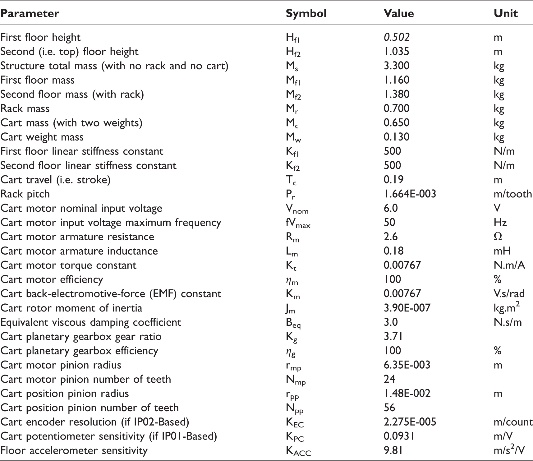
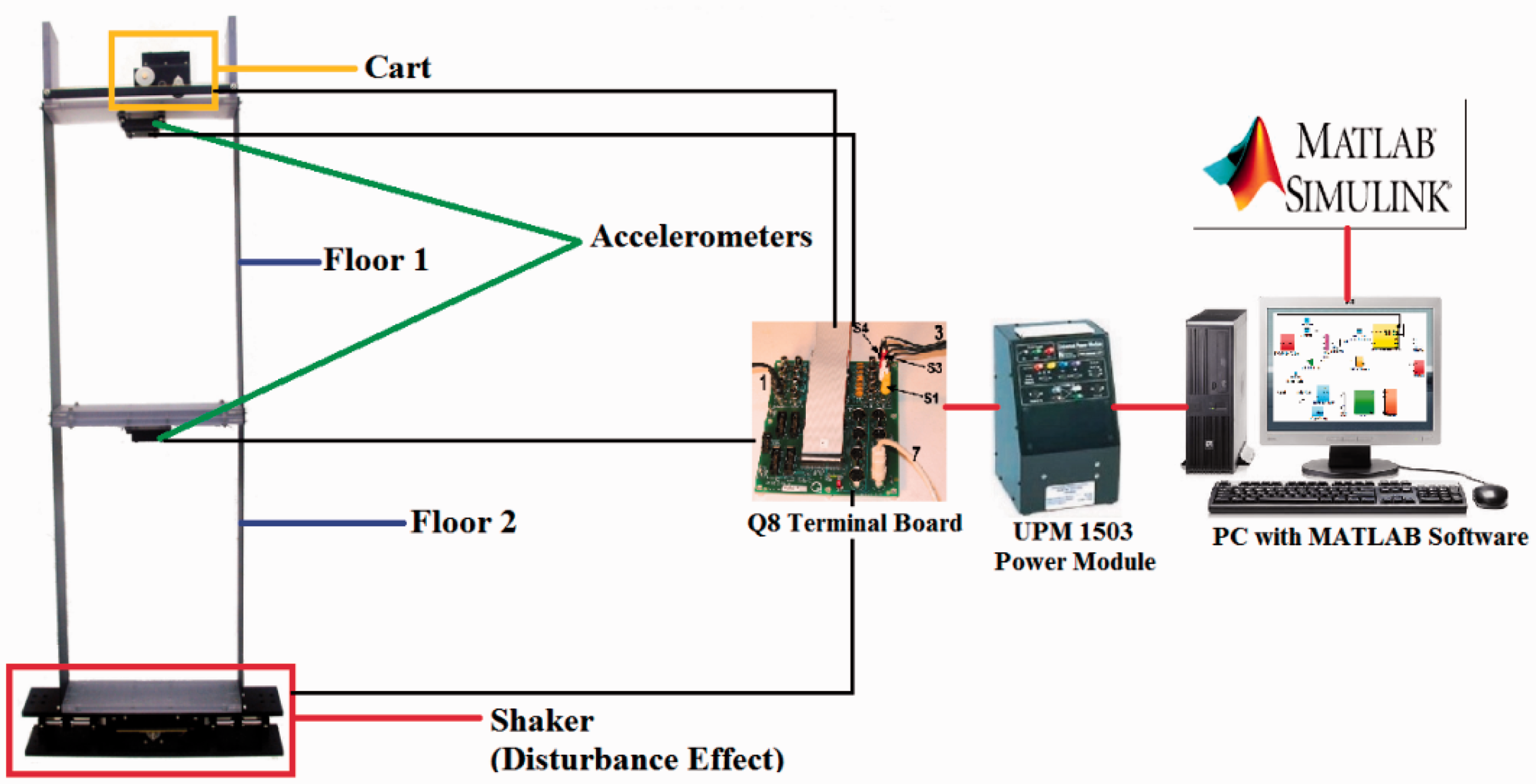
of The Active Mass Damping – Two-Floor experiment plant manufactured by Quanser Consulting Inc. is briefly summarised in this section. In Figure 1, schematic representation of the AMD-2 plant and experimental setup with shaker system is presented. In Table 1, the main parameters associated with AMD-2 system are presented. The purpose of the linear cart’s control is to dampen the second and middle floor oscillations. The full-scaled building system is a two-degree-of-freedom (2–DOF) structure. As shown in Figure 1, the linear moving cart with a DC motor is used as active mass damping and acceleration (
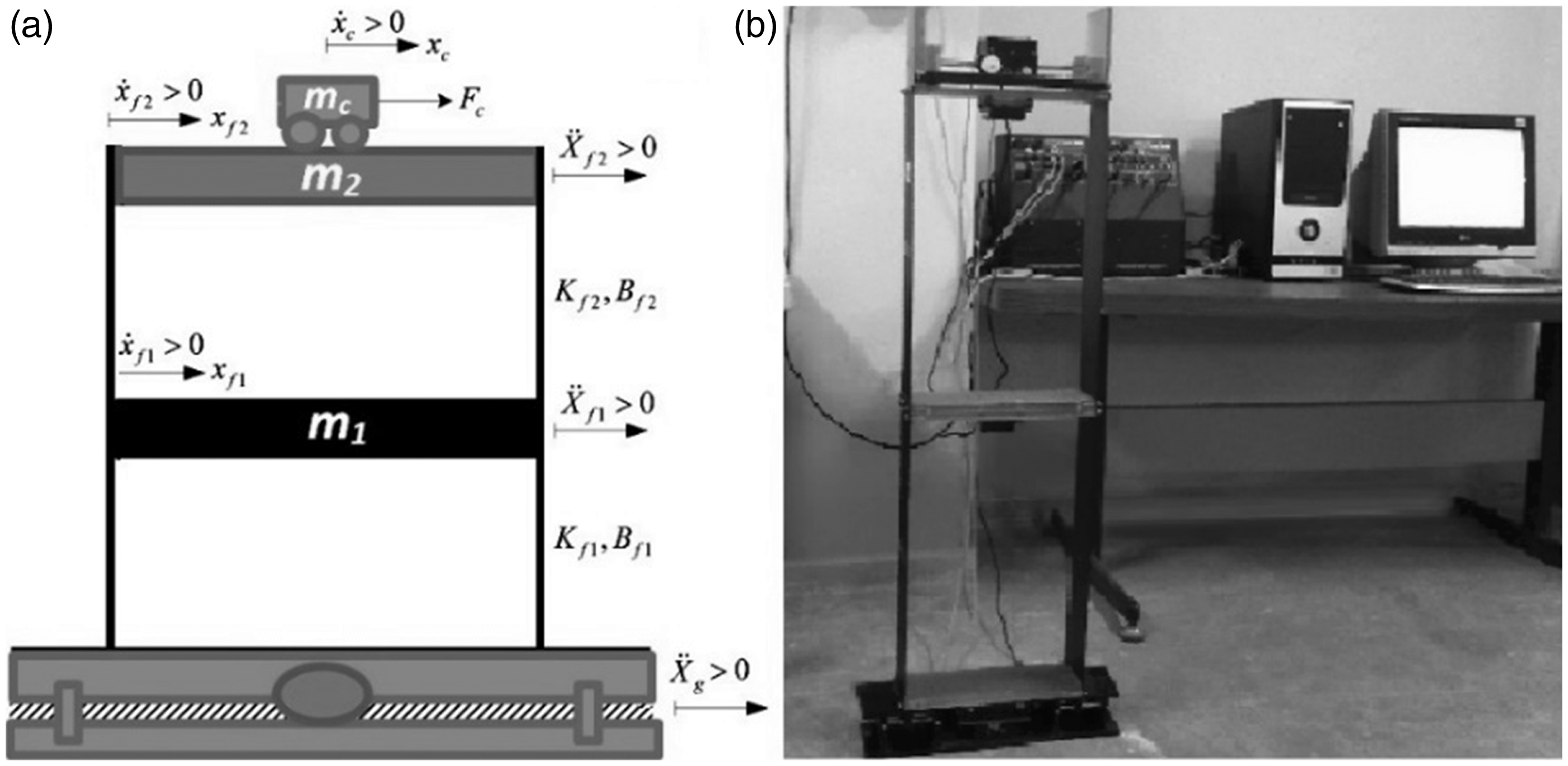
(a) Schematic diagram of the AMD system, (b) experimental setup of the AMD system.
The main parameters of AMD-2 system.
The equation of motion of system can be given under the state–space matrices representation.

In equation (1), X is the state vector of system and 
In equation (2), xc is the cart linear position relative to the second floor, xf1 and xf2 are deflections of the floors. Also, the system’s measured output vector is
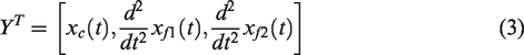
As described in equation (4), the input U(t) is set for the first time to be Fc(t), the driving force of the linear motorised cart and it is equal to linear cart’s DC motor voltage Vm(t).

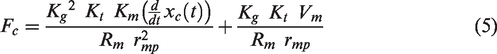
It can be seen from equations (3) and (4) that the system consists of three outputs for one input. In this case, Fc can be expressed by
The Lagrange’s method is used to obtain the dynamic model of the AMD-2 system. It can be seen from equation (6) that the potential energy (VT) of system can be expressed.

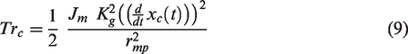
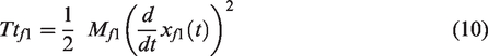
The kinetic energy measures the amount of energy in a system due to its motion. The total kinetic energy (TT) is the sum of the translational (Ttc) and rotational (Trc) kinetic energies arising from the motorised linear cart and the translational kinetic energy (Ttf1, Ttf2) of the flexible structure’s two floors. In equation (7), the total kinetic energy of the system can be formulated.

The translational (equation (8)) and rotational (equation (9)) kinetic energies arising from the motorised linear cart, the structure first floor's translational kinetic energy (equation (10)) and the structure’s second floor’s translational kinetic energy (equation (11)) can be formulated as shown by the following equation


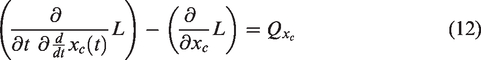
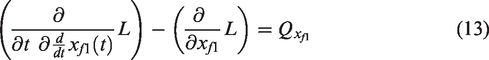
By definition, the three Lagrange’s equations (equations (12) to (14)) resulting from three generalised coordinates (xc, xf1, xf2) have the following formulations. In equation (15), L is defined that is called the Lagrangian. For the system, the generalised force can be defined in equation (16).
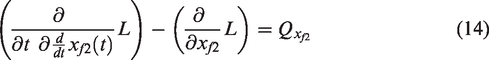


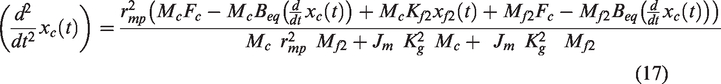
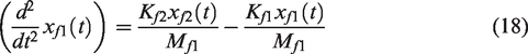
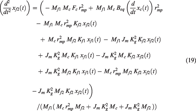
Solving the set of the three Lagrange’s equations, for the second-order time derivative of the three Lagrangian coordinates results in the following equations. Equations (17) to (19) represent the equations of motion of the AMD-2 system.
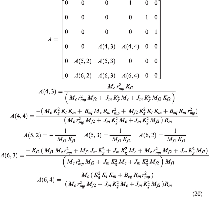
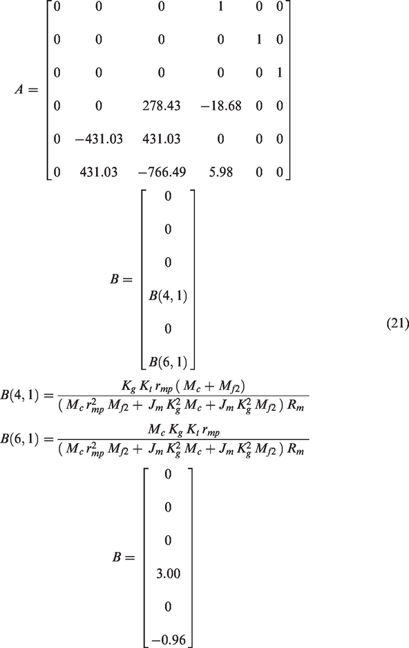
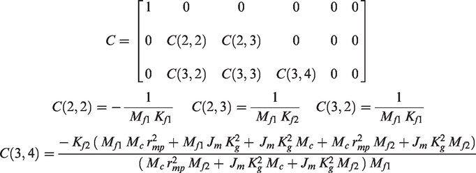
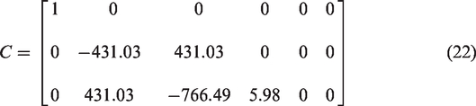
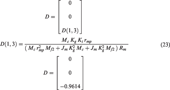
Taking into account the equations of motion, the system’s state–space matrices A, B, C, and D found for a force input can be converted to voltage input. Moreover, the state–space matrices are evaluated using the model parameters of the system given in Table 1. The state–space matrices of the AMD-2 system are shown in equations (20) to (23).
The 1994 Northridge Earthquake occurred on 17 January, at 04:30:55 a.m. Pacific Time Zone in Reseda, a neighborhood in Los Angeles, CA. Its duration is approximately 10–20 s. The earthquake had a “strong” moment magnitude (Mw) of 6.7, which produced ground acceleration that was one of the highest ever instrumentally recorded in an urban area in North America, measuring 1.7 g (16.7 m/s2) with strong ground motion felt as far away as Las Vegas, NV, about 220 miles (360 km) from the epicenter. The Northridge had a maximum displacement of 16.92 cm and this was scaled down to 1.5 cm (as set by xmax). To achieve the same acceleration as Northridge Earthquake, the time of the generated trajectory is compressed from 39.98 to 11.91 s. Figure 2 shows the recorded earthquake of the Northridge Earthquake, acceleration in gravitational units (the top plot) and the scaled position set point in centimeters (the bottom plot). Real acceleration and scaled position of Northridge are shown in Figure 2.
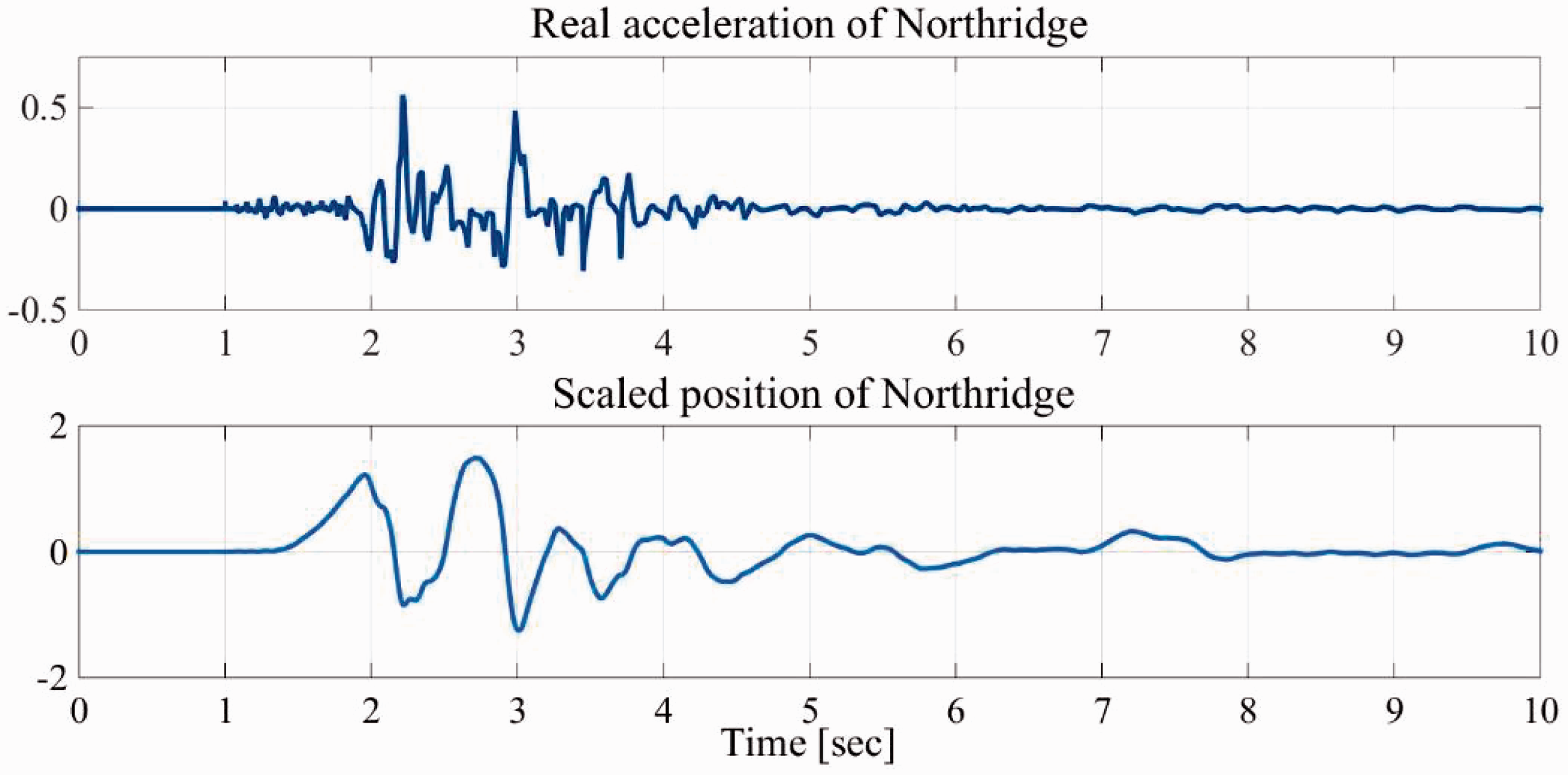
Real acceleration and scaled position of the Northridge Earthquake.
Experimental setup of two floors structure system
In this section, Experimental setup manufactured by QUANSER Consulting Inc. 32 is described in detail. Experimental setup of proposed system consists of four components which are shake table, two floors and a cart as active mass damper. The floors are set up on shake table and also disturbances are created by using shake table-like seismic excitation. Active mass damper system is a cart which is mounted on the second floor as to be moveable linear direction and it is used to suppress structural vibrations and displacements in active mode. Experimental setup of the two-floor building model is present in Figure 3.
Experimental setup of two-floor building model.
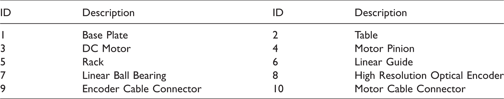
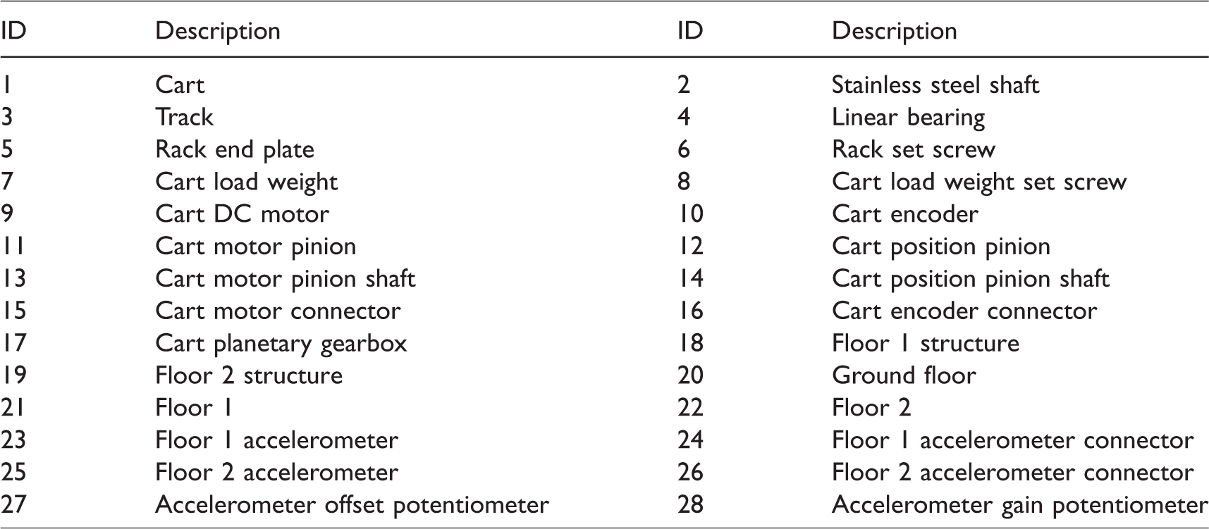
Each floor’s geometrical parameters are defined as follow: height 0.50 m, length 0.32 m and depth 0.11 m. The length, height and depth of cart are defined as 0.31 m, 0.13 m and 0.11 m, respectively. Other experimental setup requirements are listed as Q8 terminal board cart, two UMP, 1503 power modules, Pc and MATLAB/Simulink software. Descriptions of shake table, two-floor structure and cart systems are given in Figures 4 and 5 and Tables 2 and 3, respectively.
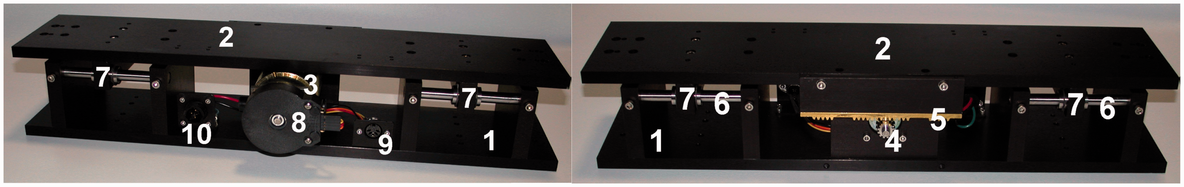
Front and back view of shake table.
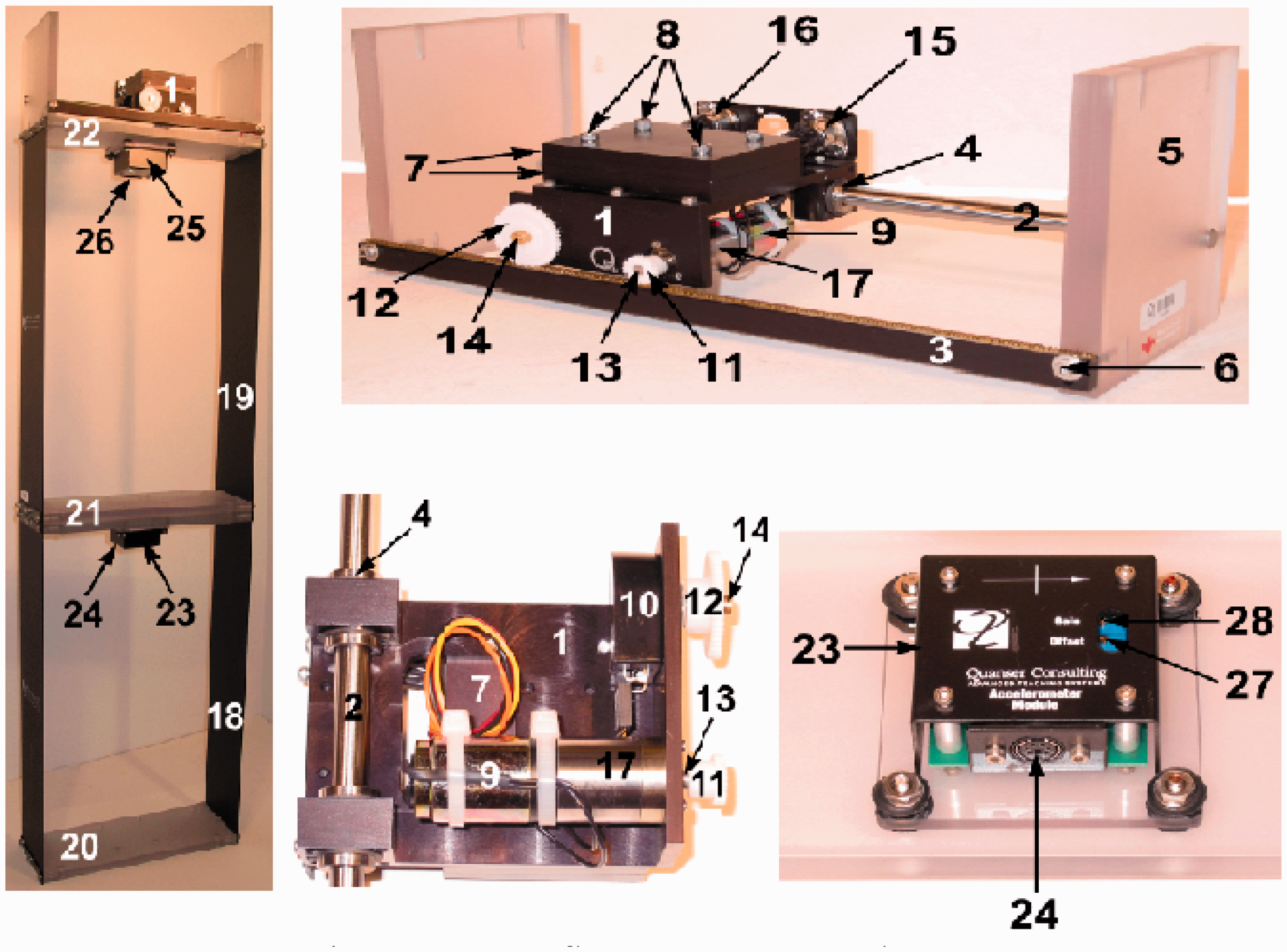
Two floors’ structure and cart.
Shake table component description.
Two floors structure and cart description.
The shake table consists of a high torque direct drive motor that can drive a 5 kg mass at 1 g maximum travel is ± 2 cm. Shake table is used to create disturbances, simulate earthquakes and evaluate the performance of active mass dampers. Geometrical parameters of the shake are defined in Table 2, which are length 0.508 m, width 0.152 m, height 0.089 m and total mass 10.8 kg.
The floors are made of two identical single-story modules connected on top of each other. Each single-story structural module consists of two steel beam-columns. Each steel column has a section of 1.75 by 108.1 mm. and a mass of 0.240 kg. Each floor of the building-like structure is equipped with a capacitive DC accelerometer with full-scale range of ±5 g. It consists of a single-chip accelerometer with signal conditioning. The accelerometer has the capability to measure both AC/dynamic accelerations and DC/static accelerations. To best measure the floors’ vibrations, both accelerometers are mounted such that their sensitive axes are longitudinal to the structure.
The bees algorithm and genetic algorithm for PID controller design
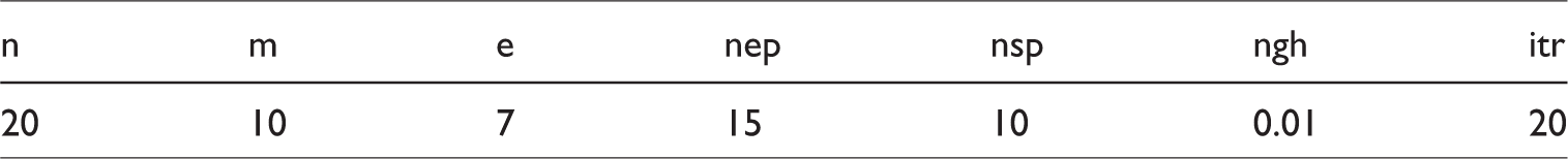
The bees algorithm is an intelligent swarm-based optimisation method to solve many complex multi-variable optimisation problems. The pseudo code for the algorithm is shown in its simplest form in Figure 6. As detailed in leading studies,33–41 the algorithm requires a number of parameters to be set, namely: number of scout bees (n), number of sites selected for exploitation out of n visited sites (m), number of top-rated (elite) sites among the m selected sites (e), number of bees recruited for the best e sites (nep), number of recruited for the other (m-e) selected sites (nsp), initial size of each patch (a patch is a region in search space that includes a visited site and its neighbourhood) and stopping criterion is iteration number (itr). The algorithm begins with the n scout bees being placed haphazardly in the search space. In step 2, the fitness of the sites visited by the scout bees is evaluated. In step 3, the m sites with the highest fitness are designated “selected sites” and chosen for neighbourhood (ngh) search. In steps 4 and 5, the algorithm conducts searches in the neighbourhood of the selected sites, assigning more bees to the best e sites. Selection of the best sites can be made directly according to the fitness associated with them. As an alternative, fitness values can be used to determine the likelihood of sites being selected. Searches in the neighbourhood of the best e sites which represent the most promising solutions are made in a more detailed manner by recruiting more bees for them than for the other selected sites. Together with scouting, this differential recruitment is a key operation of the bees algorithm. In step 5, for each patch, only one bee that has found the site with the highest fitness (the “fittest” bee) will be selected to form part of the next bee population. In steps 6, 7 and 8, the remaining bees in the population are assigned haphazardly around the search space scouting for new potential solutions. These steps are repeated until a stopping criterion is met. At the end of each iteration (itr), the colony will have two parts to its new population – representatives from each selected patch and other scout bees assigned to conduct haphazard searches.
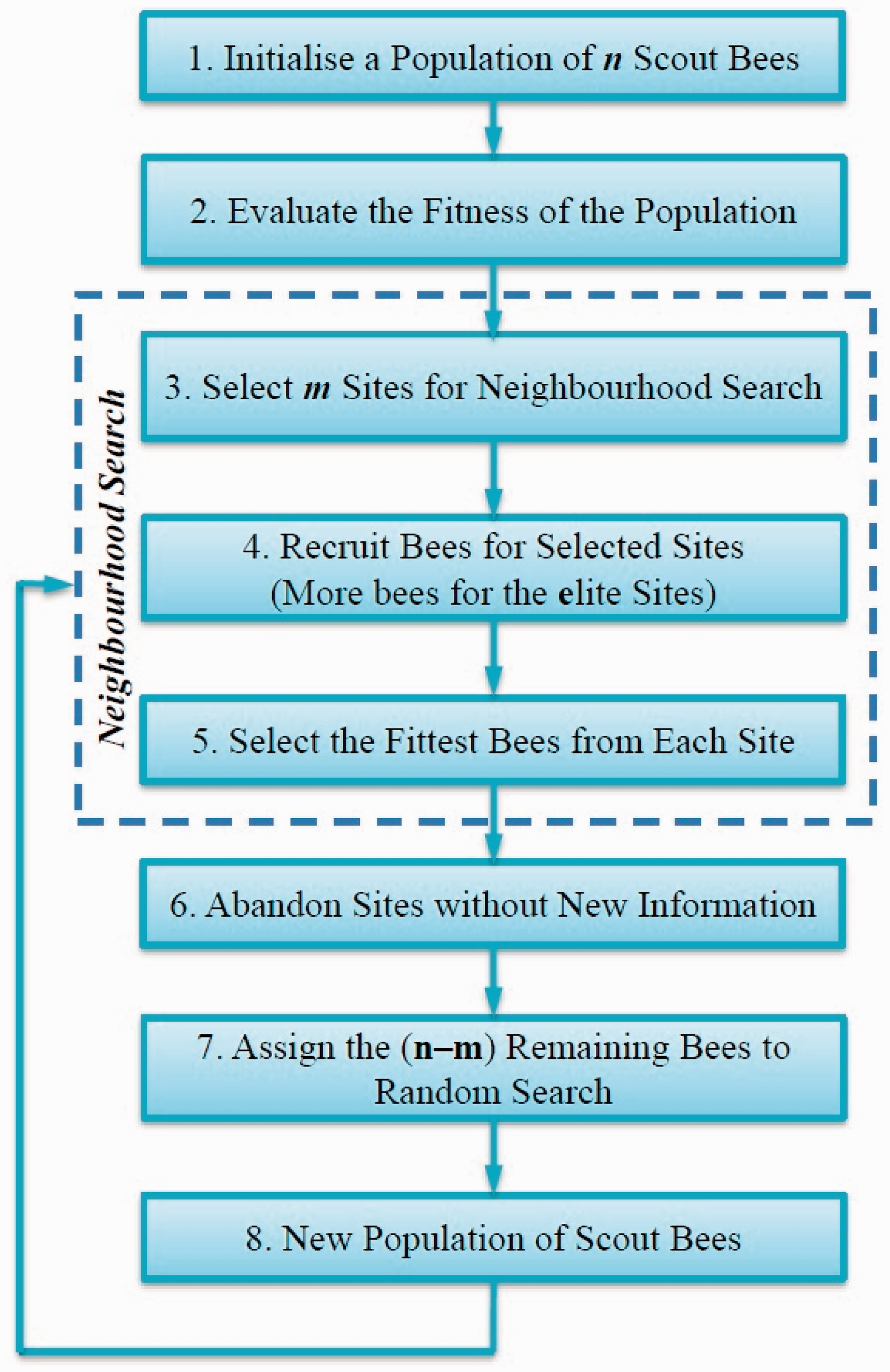
Pseudo code of the bees algorithm.
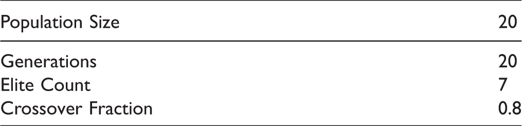
Genetic algorithm (GA) 42 is an adaptive heuristic search algorithm based on the process that mimics natural selection and genetics. Genetic algorithm is a particular class of evolutionary algorithms that use techniques inspired by evolutionary biology such as inheritance, mutation, selection, and crossover. Because genetic algorithm is a widely used search technique to find true or approximate solutions to optimisation, it is used as a benchmark technique to compare performance of the bees algorithm in this study. In optimisation with genetic algorithm, MATLAB Global Optimisation Toolbox 43 is used, which is a powerful tool to solve optimisation of problems.
In Figure 7, PID controller block diagram of system is given. A PID controller is designed to control the driving voltage of the cart, and PID gain parameters (KP, KI and KD) are determined by tuning with the bees algorithm and genetic algorithm to provide the minimum deflection of the floors under Northridge Earthquake. For this goal, maximum deflections of the floors are defined as 3 cm for the first floor and 2 cm for the second floor. In addition, because the most destructive effect of the earthquake occurs between 2 and 6 s according to passive mode deflection results of the floors, the damping time (nearby to zero deflection) is set to under 6 s.
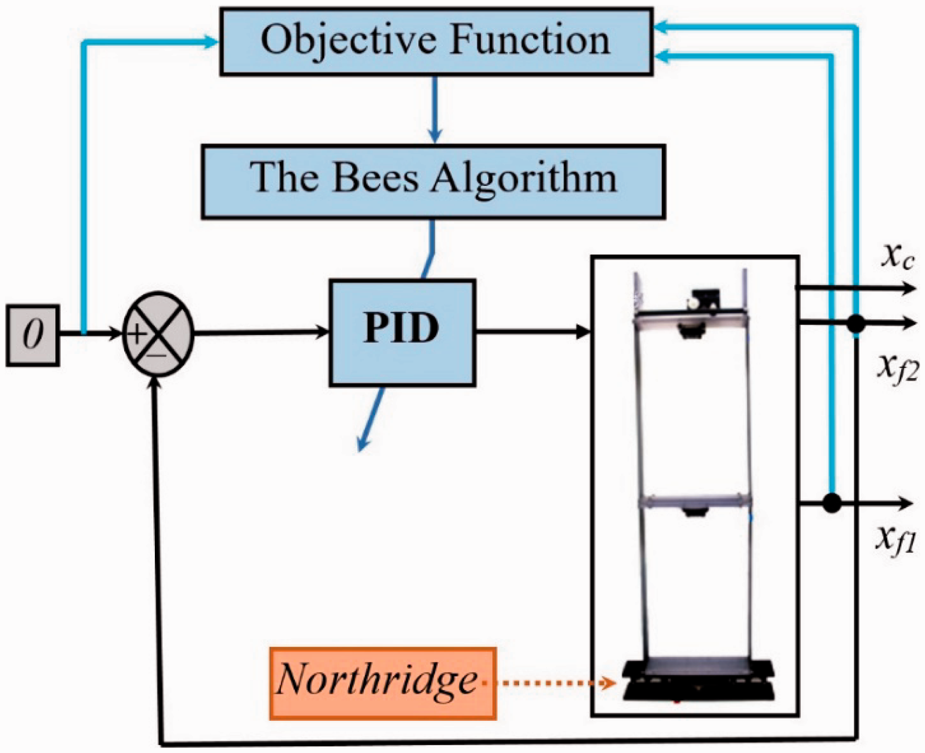
Block diagram of PID controller tuning in Simulink.
In the control criteria, the idea is to search for the optimal values of the gains of PID controllers with respect to a determined objective function which consist of deflection of the floors. The objective function (J) is

The bees algorithm parameters.
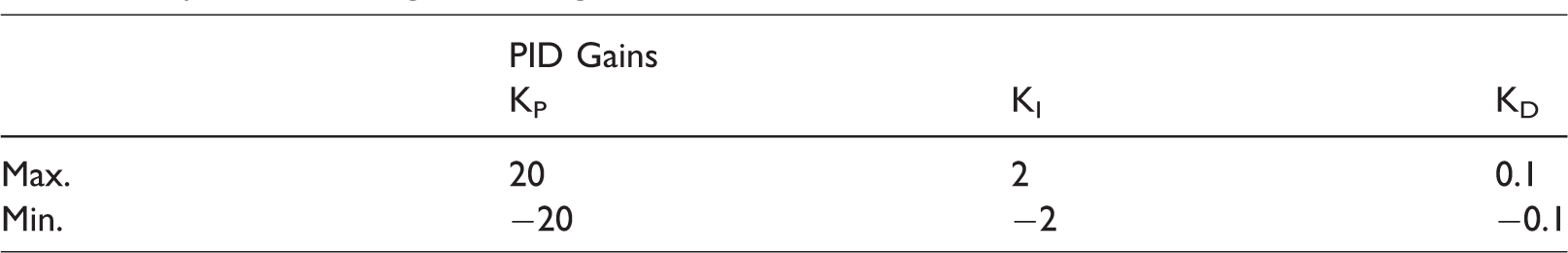
Optimisation ranges of PID gains.
Genetic algorithm parameters.
Experimental results and discussion
The aim of this paper is not only to tune of the PID controller with the bees algorithm and genetic algorithm for the experimental system, but also to improve the controller by decreasing deflections of floors. In this section, the experimental results and performance of the proposed tuning methods are investigated in detail. In general, passive mode is without controlled mode, and active mode is controlled mode in this manuscript.
The passive mode results of the system are given in Figure 8. As seen in Figure 8(a), the first and second floor maximum deflections in passive mode are obtained as 2.0756 cm and 2.2067 cm, respectively. Generally, the first floor deflection is more than that that of second floor but on the other hand acceleration magnitude of the second floor is more than the first floor’s result.
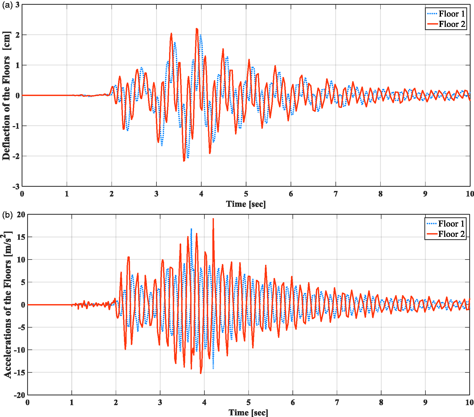
Passive mode responses of the floors (a) and (b).
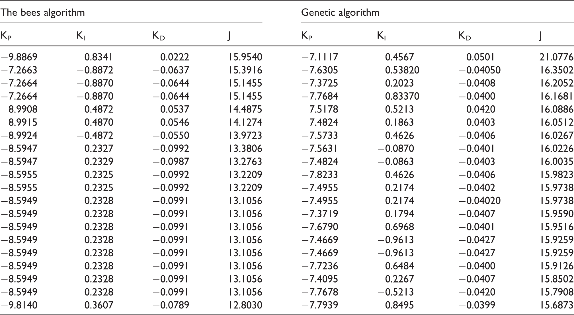
In existent study, 27 PI controller gains for the system are KP = −1.8, KI = 0.2 which are determined as initial values of the optimisation. The PID controller designed by the bees algorithm and genetic algorithm implemented on the AMD system. As seen in Table 7 for the bees algorithm − genetic algorithm, the objective function value (the cost) reduced to 12.8030 – 15.6873. The optimal gains provide this objective function value obtained for the PID controller are KP = −9.8140, KI = 0.3607, KD = −0.0789 − KP = −7.7939, KI = 0.8495, KD = −0.0399. Figure 9(a) shows the active mode deflections and accelerations of the floors with tuned PID-controlled AMD. From Figure 9(a), the amount of total deflection of the floors is less than passive mode deflection responses, maximum deflections for floor 1 is 0.6504 − 0.7784 cm and for floor 2 it is 0.6482 − 0.7909 cm, also deflection criteria of the floors are provided with PID controller. Moreover, the damping time of AMD is evaluated as 5 s.
Gains of the PID controller list.
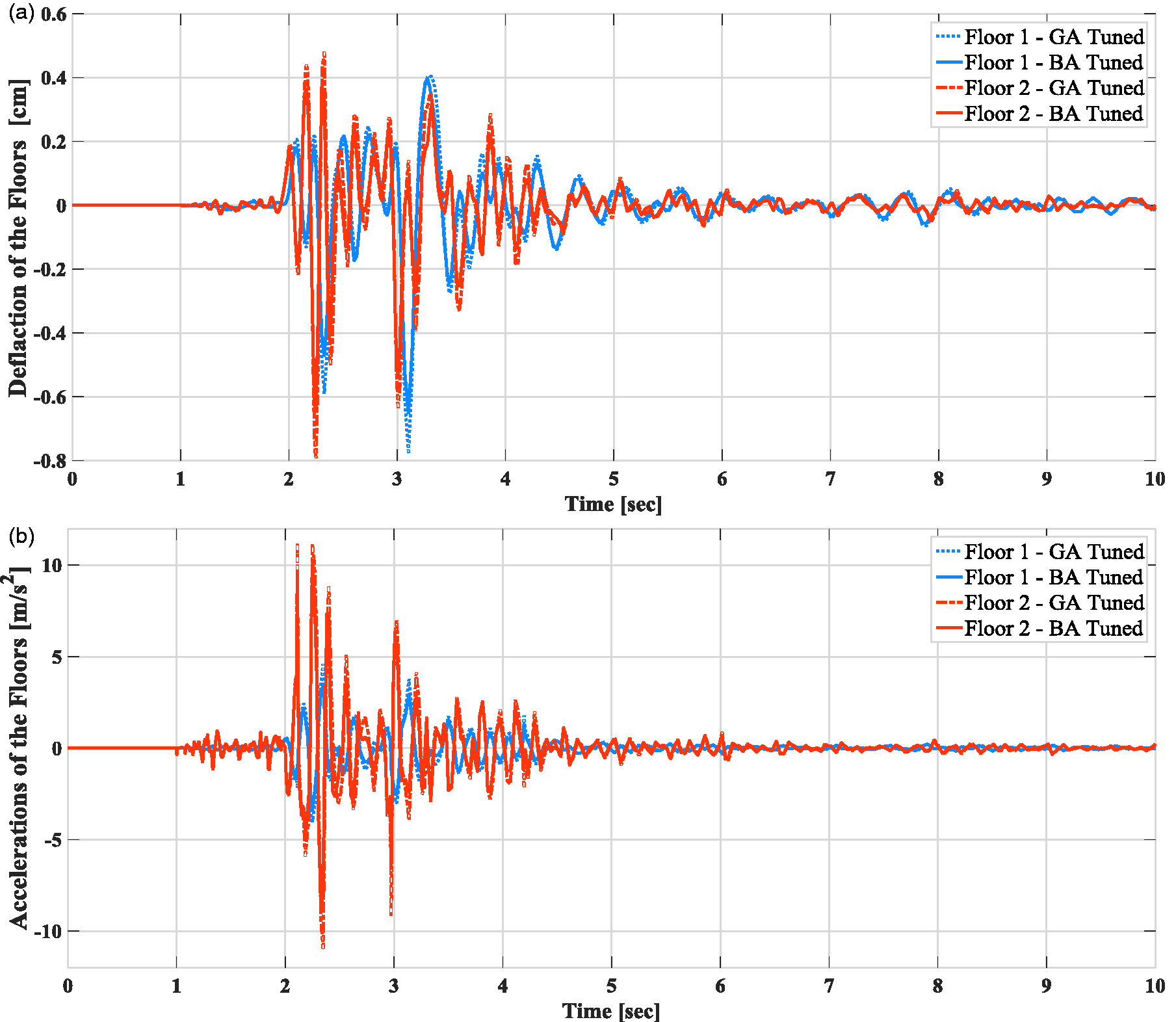
Active mode responses of the floors after tuned PID controller (a) and (b).
In Figures 10 to 12, passive mode is named as ‘uncontrolled’, active mode is named as ‘without tuned’ before tuning which is PI controlled mode with existent gains. Also active mode is named as ‘BA tuned’ and ‘GA tuned’ after tuning using the bees algorithm and genetic algorithm which is PID controlled mode with optimal gains.
Without tuned, GA tuned and BA Tuned PID controlled deflections of the floors are compared and presented in Figure 10(a) and (b). Also the effects of tuning on PID controlled cart displacement under Northridge are shown in Figure 10(c). Figure 10(a) and (b) shows that the structure damping effect of tuned PID controlled cart is significantly increased by minimizing the deflections of floors. According to without tuned, it can be said that tuned PID controller with the bees algorithm and genetic algorithm decreased first floor maximum deflections by 48.8% and 38.7% and average deflections by 61.2% and 54.8%, second floor maximum deflections by 46.6% and 34.8% and average deflections by 62.7% and 54.3%. Tuned PID controlled cart suppresses the deflections more. Also displacement and control voltage of PID controlled cart ranged within acceptable values as shown in Figure 10(c) (d).
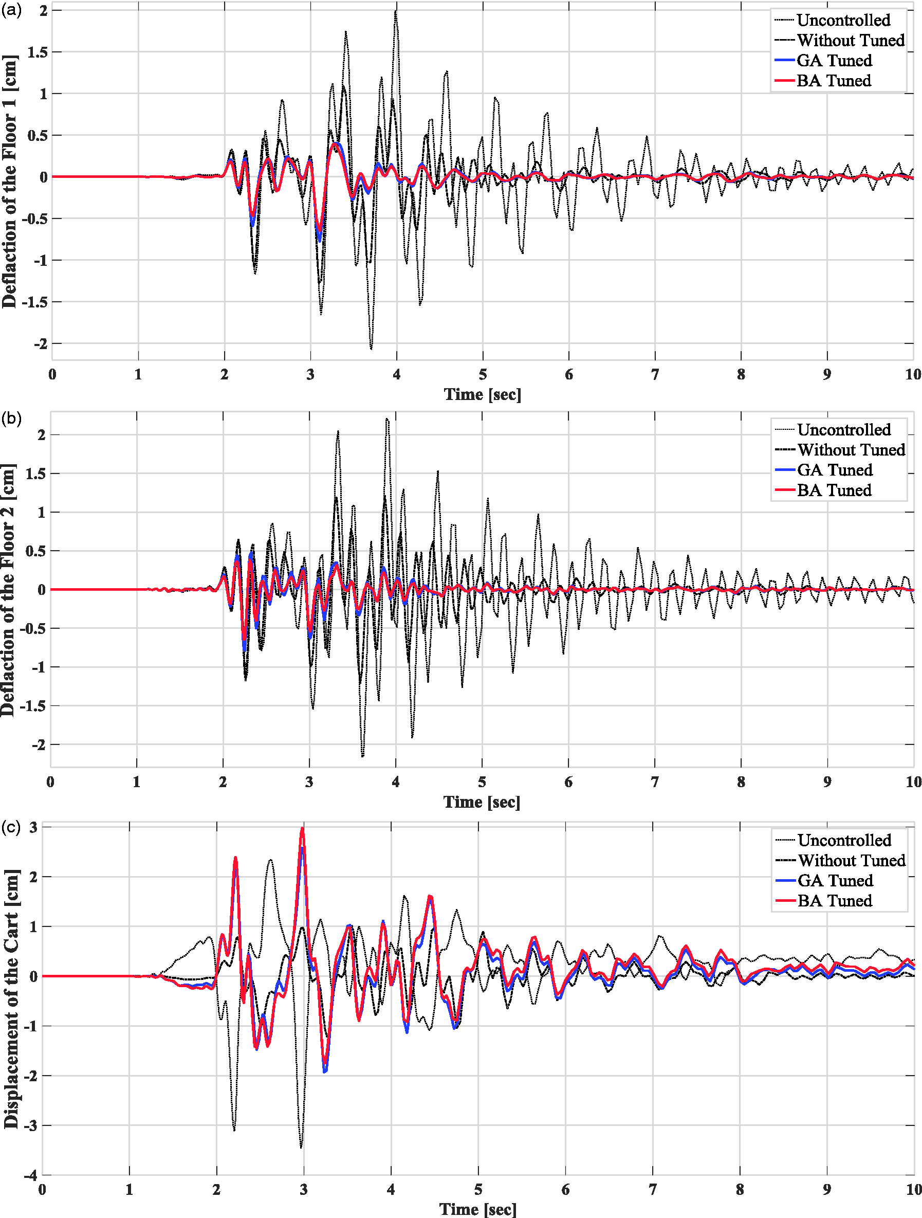
Comparison of tuned with BA and without tuned PID controller. Deflections of the floor 1 (a), deflections of the floor 2 (b), displacements of cart (c), and control voltage of cart (d).
Similarly to Figure 10, without tuned, GA tuned and BA tuned PID controlled accelerations of the floors and cart are presented in Figure 11(a) to (c), respectively. It is clearly seen in Figure 11 that the tuned PID controller suppressed accelerations of the floors and cart very effectively. According to without tuned, ıt can be said that tuned PID controller with the bees algorithm and genetic algorithm decreased first floor maximum accelerations by 73.8% and 64.7% and average accelerations by 64.8and 57.5%, secind floor maximum accelerations by 28% and 19.6% and average accelerations by 44.7% and 34.9%. It seems obvious from Figures 10 and 11 that the bees algorithm is a more effective PID tuning method than genetic algorithm to the deflection and accelerations control of the floors against unexpected threats such as earthquake.
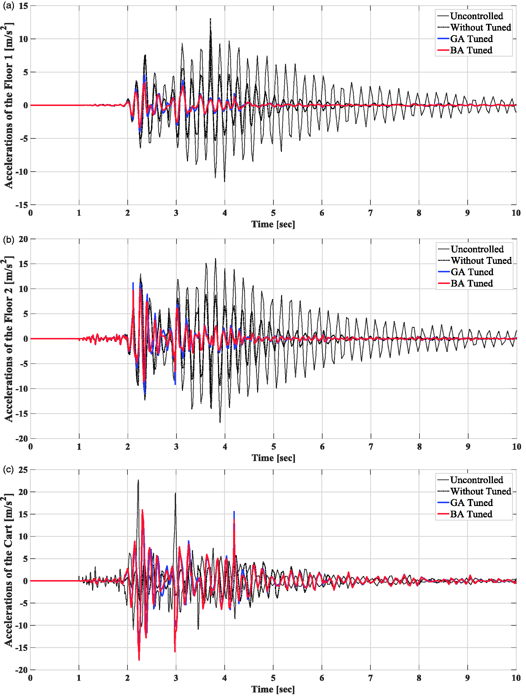
Comparison of tuned with BA and without tuned PID controller. Accelerations of the floor 1 (a), accelerations of the floor 2 (b), and accelerations of cart (c).
By examining the relevance between deflection/accelerations of the floors and control voltage of the cart, Figure 12(a) and (b) shows the comparisons of voltage versus deflection of the floor 2 and voltage versus velocity of floor 2 for Without Tuned, GA Tuned and BA Tuned of PID-controlled cart. A close correlation between responses improves the reliability of the tuning methods.
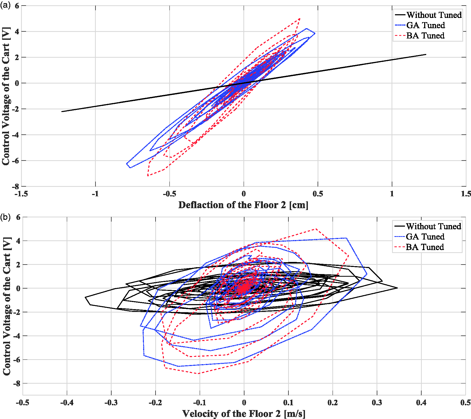
Voltage versus deflection of the floor-2 (a) and voltage versus velocity of the floor-2 (b).
The bees algorithm is programmed in MATLAB and genetic algorithm is a tool in MATLAB Global Optimisation Toolbox run on an Intel(R) Core(TM) i7–4700HQ CPU 2.40 GHz PC with 16.0 GB memory separately. Both algorithms run for 20 iterations to find minimum cost function value which is defined as the objective function (J) in equation (24). In terms of performance criteria of the bees algorithm−genetic algorithm, computing time of optimisation is 158.1 − 26.3 s and the ratio of CPU usage is approximately 19–21%. Complexity analysis of the bees algorithm is extensively investigated and also comparative results with other optimisation algorithms in benchmarking studies.44,45 The performance analysis of both algorithms to tune of the PID controller for the system is determined and is presented graphically in Figure 13. As seen obviously, the bees algorithm is converged better at the end; it gives better solutions at finding global and local minima than genetic algorithm. Additionally, the tuned PID gains and comparison of experimental results are given in the form of a list in Tables 7 and 8, respectively.
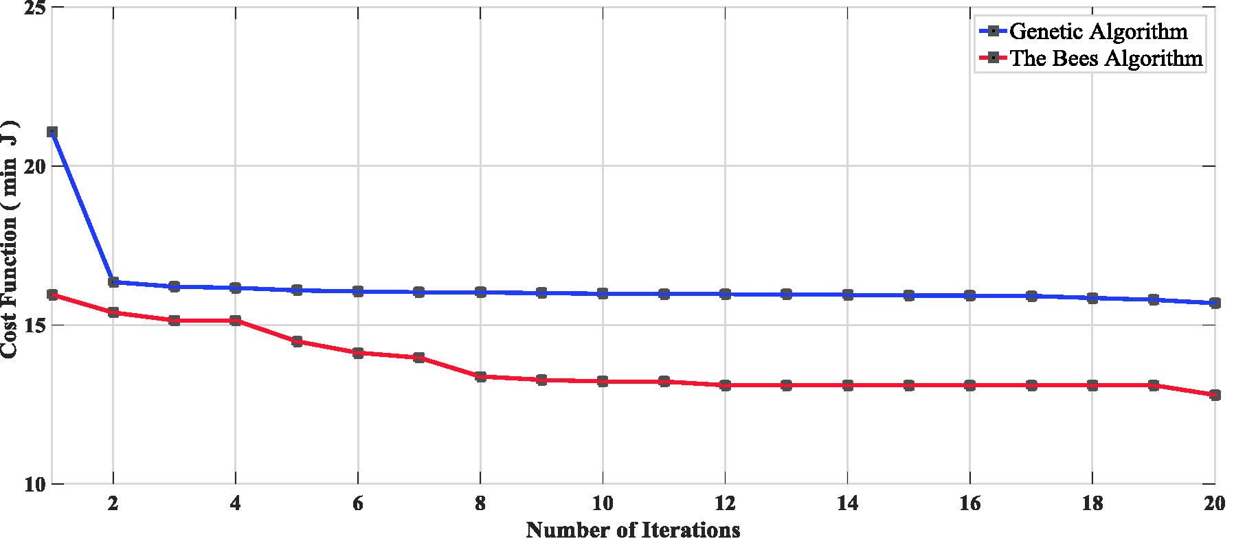
The performance analysis of the bees algorithm and genetic algorithm.
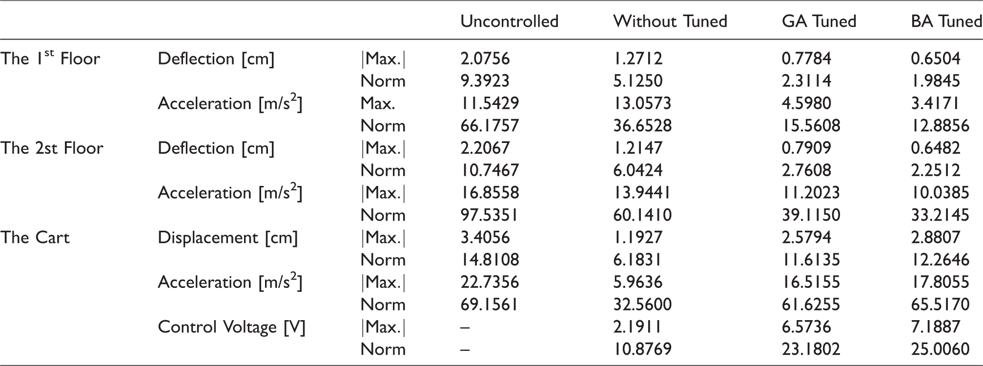
Comparison of experimental results List.
Conclusion
In this paper, optimisation of a PID controller for a two-floor structure under earthquake excitation using the bees algorithm and genetic algorithm is investigated by experimental methods. It has presented the tuning of a PID controller for a mass damping system to the deflection control of a two floors building-like structure system against scaled the Northridge Earthquake. In order to compare the performances of the bees algorithm with a commonly used tuning algorithm, it is compared with genetic algorithms. Both algorithms are used to find optimal PID controller gains for optimum controller performance over the proposed system. The existent gains are tuned to minimise the objective function which consists of floors’ deflections values. Without tuned, GA tuned and BA tuned of PID controlled and uncontrolled of cart are compared with each other in figures. The experimental results indicate that the tuning PID controller with the bees algorithm provides more absorbing than genetic algorithm due to the scaled Northridge earthquake within controller design criteria. Furthermore, as it can be seen clearly from the graphs, tuned gaıns of PID controller by using both algorithms managed to reduce emissions dramatically compared to to without tuned. The comparative experimental results clearly showed that the bees algorithm can be used as a diverse method to tuning of PID controller. The tuned PID controller has a sufficient performance when essential performance requirements under seismic excitation for the safety of the structure and comfort level for the user are considered. The most important advantage of this approach is that traditional methods such as trial and error which are mostly used in optimisation of PID controller in control systems are not needed. Needed performance requirements of proposed system against disturbance effects such as the scaled Northridge are achieved by using tuned PID controller. PID controller performance can be improved by changing the bees algorithm parameters as well as the objective function and the optimisation range. In future studies, various type controllers, which are intelligent and adaptive, will be designed with the bees algorithm to improve controller performance for structure system under effect of different real earthquakes. All these obtained results are supposed to guide the relevant studies in this field since this study has the ability of being improved.
Footnotes
Declaration of conflicting interests
The author(s) declared no potential conflicts of interest with respect to the research, authorship, and/or publication of this article.
Funding
The author(s) disclosed receipt of the following financial support for the research, authorship, and/or publication of this article: This study is supported by the Coordinator ships of Selçuk University’s Scientific Research Projects (Project No: 09401048).