
Abstract
This study develops and validates a force feedback control system for automotive pedals utilizing an optimized PID controller using the hybrid Spiral Sine-Cosine algorithm (SSCA). The primary objective is to enhance system performance by integrating SSCA-tuned PID control and comparing results from simulation and Hardware-in-the-Loop (HIL) testing. Auto Regressive with Exogenous inputs (NARX) models were used as the system identification method for nonlinear dynamic system to accurately represent actuator and pedal force relationships. Results demonstrated that the HIL setup significantly improved performance metrics compared to simulations: overshoot decreased, rise time improved, and settling time reduced for various force parameters. The study confirms that SSCA-tuned PID control can be effectively implemented in real-life applications, particularly in force control pedal vehicles, with potential benefits including reduced driver fatigue due to the repetitive actions of pressing and releasing the vehicle pedal. Future research will aim to enhance this approach by integrating vehicle speed control with advanced actuator and pedal force control systems. This integration will ensure smoother and more precise control over vehicle dynamics, improving overall responsiveness and efficiency. Moreover, a primary focus will be on optimizing low-speed driving scenarios, particularly in traffic congestion, where precise control is critical. By addressing challenges such as stop-and-go movement, vehicle jerks, and energy efficiency, this research seeks to enhance both driver comfort and safety in urban traffic conditions.
Keywords
Introduction
In the realm of mechatronics and automation, precise control of force in various applications such as robotics, 1 manufacturing, 2 and biomedical devices3,4 is crucial. The ability to manipulate forces accurately and dynamically opens avenues for enhanced performance, safety, and efficiency in diverse engineering domains. For instance, in robotics, force control is essential for tasks requiring delicate manipulation or interaction with uncertain environments. In manufacturing, precise force control ensures consistent product quality and process efficiency, while in biomedical devices, it enables advanced prosthetics and minimally invasive surgical tools.
This capability is especially relevant in the automotive industry, where force feedback control applied to pedals in vehicles represents a significant advancement in technology. Traditionally, vehicle pedals rely solely on mechanical linkages and hydraulic systems to transmit forces from the driver’s foot to the vehicle’s braking or acceleration mechanisms. However, the introduction of force feedback technology introduces a new dimension by enabling the application of programmable resistive forces or vibrations directly onto the pedals.
Pedals in vehicle, such as brake and accelerator pedals, are crucial interfaces through which drivers exert control over vehicle speed and maneuverability. In practical terms, force feedback on pedals involves the use of electromechanical actuators the resistance felt by the driver’s foot based on simulated driving conditions or virtual environments. This capability not only enhances the realism of driving simulators but also allows for precise calibration of pedal responses to simulate varying road conditions, vehicle loads, and braking intensities.
In order to achieve effective force feedback control on vehicle pedals, a robust controller is essential. This controller supplies appropriate control signals to electromechanical actuators, ensuring that the desired resistive force is accurately applied. It continuously monitors the force exerted by the driver’s foot and dynamically adjusts the actuator’s output to match programmed feedback conditions. By comparing the actual force with the target force, the controller generates corrective signals to adjust the actuator’s behavior, maintaining precision and responsiveness. One well-known controller is the PID controller, commonly used due to its ability to fine-tune control signals based on the error between the actual and desired force. The PID controller is also easy to use and has one of the highest success rates in the automotive industry compared to other intelligent controllers such as fuzzy logic and state space, which require deep understanding and expertise. 5 According to Ref.6, 90 to 95% of control loops system are PID-based.
However, the process of fine-tuning a PID controller’s parameters is challenging. It often relies on traditional methods such as trial and error, Ziegler-Nichols, and Cohen-Coon, which can be time-consuming, retuning, and may not always yield optimal results.7,8 Isa et al. 9 and Hashim et al. 10 focus on developing systems to reduce driver fatigue from frequent pedal pressing during traffic congestion. Both studies utilize a linear actuator controlled by a PID controller to replicate the pressing and releasing actions of a driver’s leg. Isa et al. integrate the actuator’s mathematical model with a car dynamic model in Simscape, achieving a force of about 200 N and a response time of less than one second to stop the vehicle, closely matching human performance. Hashim et al. create a 3D model in SolidWorks and connect it to Matlab Simulink, evaluating the PID controller’s performance with the Matlab tuner, which shows superior results in response time and steady-state error reduction. Both studies conclude that their systems can effectively replace manual pedal actions, reducing driver fatigue. However, both studies focus solely on simulation environments, where classical PID tuning appears effective. Real-time testing may present significant challenges and issues not encountered in simulations. Therefore, PID tuning strategies should be developed to work effectively in both simulation and real-time testing to address potential issues and ensure robust performance. As a result, many researchers today are shifting their focus to exploring alternative ways to enhance PID controller performance, such as optimization techniques.
Optimization techniques are advanced methods used to enhance PID controller performance by automating parameter tuning. Inspired by natural phenomena, these techniques mimic biological and physical processes to find optimal solutions. Some examples are Particle Swarm Optimization,11–13 Cuckoo Search Algorithm,14,15 and Artificial Bee Colony (ABC) algorithm,16–18 which is inspired by the foraging behavior of honey bees. The Spiral Dynamic Algorithm (SDA) is based on natural spiraling movements.19,20 However, these techniques face several challenges. For instance, the SDA may struggle with convergence speed and local optima, 21 while the ABC algorithm can be slow and computationally intensive. 22 The Grey Wolf Algorithm can lack solution diversity, trapping at local optima and may converge prematurely, 23 and the Cuckoo Search Algorithm might face difficulties balancing exploration and exploitation, leading to suboptimal solutions. 24 Researchers address these limitations by developing hybrid optimization methods that combine multiple algorithms to leverage their strengths. For example, 25 one study integrated the spiral equation from SDA into the Bacterial Foraging Algorithm (BFA), improving exploration and exploitation phases and significantly enhancing accuracy. Another study, 26 combined SDA with Genetic Algorithm (GA), incorporating GA’s mutation and crossover operations to achieve a better accuracy compared to the original GA and SDA. These hybrid approaches demonstrate improved performance in complex optimization problems.
Motivated by the challenges in existing optimization techniques, this study introduces the hybrid Spiral Sine Cosine Algorithm (SSCA), which integrates the spiral equation from the Spiral Dynamic Algorithm (SDA) with the Sine-Cosine Algorithm (SCA). This integration enhances the diversification and intensification strategies of search agents, improving both the global and local search capabilities. Compared to traditional optimization techniques such as Particle Swarm Optimization (PSO) and Genetic Algorithms (GA), SSCA is more efficient in addressing the trade-off between exploration and exploitation. The SDA component offers robust exploration capabilities, allowing the algorithm to avoid premature convergence and escape from local optima, a common issue faced by simpler methods. Meanwhile, the SCA component improves local search precision by utilizing its sine-cosine operations, which fine-tune the solutions in the vicinity of optimal regions, thus enhancing convergence speed and solution accuracy. This hybrid approach makes SSCA particularly effective in fine-tuning PID controller parameters for automated systems, where rapid adaptation and precision are essential.
Furthermore, SSCA is highly advantageous for real-time applications, especially in systems like vehicle pedal force feedback control. The algorithm’s faster convergence rate and superior stability allow it to optimize PID controllers efficiently, even in dynamic environments. Unlike other algorithms, such as the Grey Wolf and Cuckoo Search, which struggle with balancing exploration and exploitation, SSCA effectively addresses these limitations. Its optimization of PID parameters ensures that the force feedback control system remains responsive and precise, replicating realistic sensations of braking and acceleration while reducing the physical effort required from drivers. This innovation not only improves driver interaction and simulates vehicle dynamics with greater fidelity but also alleviates driver fatigue and muscle stiffness during prolonged driving, contributing to a more comfortable and less strenuous driving experience. SSCA’s ability to balance global exploration with local exploitation makes it the ideal choice for real-time PID tuning, ensuring both performance and reliability in automated systems.
The organization of this paper is as follows. The remaining sections of the paper explain the design and implementation of the automated pedal system, including the integration of electromechanical actuators and the PID control strategy. The application of SSCA for tuning the PID controller is discussed, emphasizing the steps taken to optimize performance in both simulations and real-time Hardware-in-the-Loop (HIL) testing. The paper ends with a conclusion of the work summarizes the key findings of the study, emphasizing the effectiveness of SSCA in optimizing PID controllers for automated pedal systems. The chapter also suggests potential avenues for future work, including improvements in algorithm efficiency and further applications in real-time systems.
Methodology
System identification
In the study of force feedback control for automotive pedal systems, data collection and system identification are crucial for developing an accurate model of the system. 27 The data collection process involves two primary aspects: first, capturing how varying input voltages affect the actuator’s position, and second, understanding how the actuator’s position influences the force applied to the pedal. This data is essential for elucidating the interactions between voltage, actuator position, and pedal force.
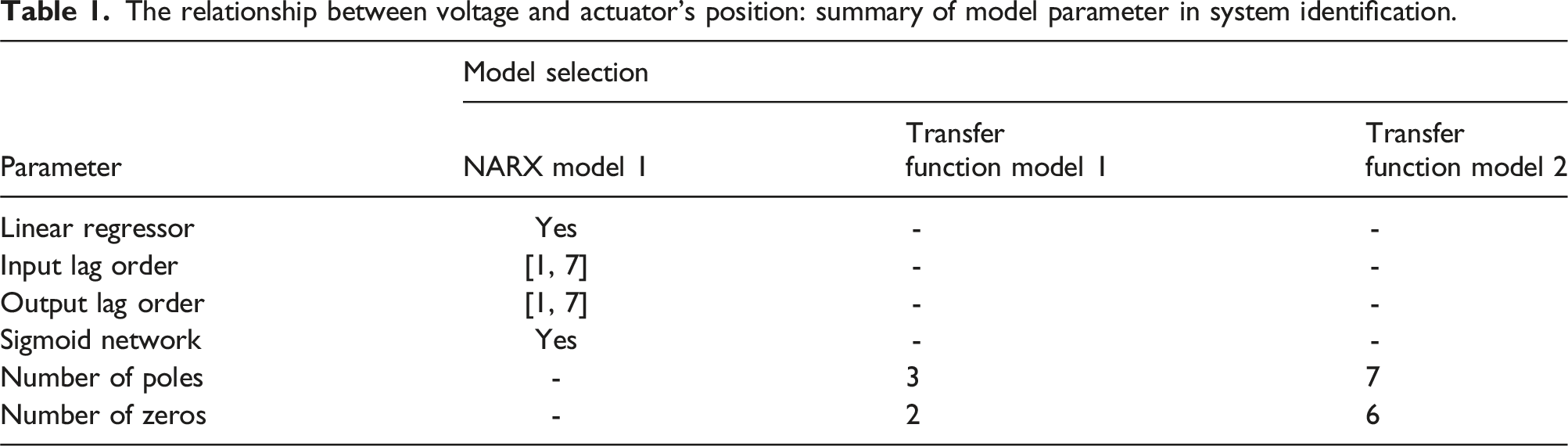
The relationship between voltage and actuator’s position: summary of model parameter in system identification.
The relationship between actuator’s position and force on vehicle pedal: summary of model parameter in system identification.
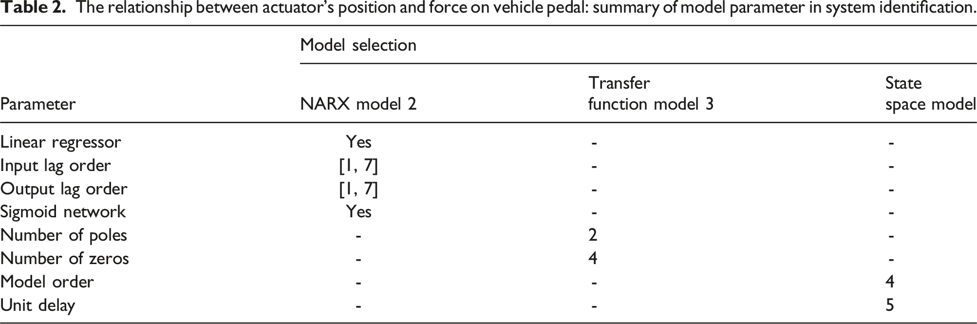
Model accuracy is assessed through goodness-of-fit measures provided by the Toolbox. Performance metrics such as mean squared error (MSE) quantify how closely the model’s predictions align with the actual data. Additionally, goodness-of-fit metrics, such as fit percentage, indicate how well the model captures the system dynamics. By focusing on nonlinear relationships and leveraging these tools, the developed model accurately represents the system, thereby enhancing the effectiveness of the force feedback control.
PID control and tuning method
Discrete PID controller
PID controllers are designed in two primary forms: continuous and discrete, each catering to different system requirements. 28 Continuous PID Controllers function in the continuous time domain, utilizing differential equations to manage analog systems where signals are processed continuously. This approach is ideal for systems that can handle real-time, analog processing with naturally continuous signals. In contrast, discrete PID controllers operate in the discrete time domain, where control actions are computed and applied at specific intervals using sampled data. This form is essential for digital control systems, including microcontrollers, digital signal processors (DSPs), and software-based systems, where signals are processed in discrete time steps.
In Hardware-in-the-Loop (HIL) Testing, discrete PID controllers become particularly necessary. HIL testing integrates real hardware with simulated systems to test and validate control algorithms. Digital HIL platforms process data in discrete time steps, making discrete PID controllers compatible with the digital nature of these systems. They are optimized for systems where measurements and control actions occur at fixed intervals, aligning with the sampling and timing characteristics of digital hardware. Moreover, discrete PID controllers facilitate the seamless integration of control algorithms with embedded controllers or real-time processing units used in HIL setups, ensuring accurate and efficient performance. Therefore, discrete PID controllers are crucial for implementing and evaluating control systems in digital and real-time environments, providing precise control and accurate simulations. Thus, the discrete PID controller can be represented as equation (1).
where K p is proportional gain, K i is integral gain, K d is derivative gain, T is sampling period, and Z is complex frequency in z-domain.
Tuning the values of K p , K i and K d in a discrete PID controller to achieve a stable system can be particularly challenging. One major difficulty arises from the interaction between these parameters, as adjusting one can influence the effects of the others. The proportional gain K p controls the system’s response speed, but setting it too high can lead to excessive overshoot and instability. The integral gain K i addresses steady-state error by accumulating past errors, yet an excessively high K i can cause persistent oscillations and increased system noise. The derivative gain K d helps to predict and mitigate future errors based on their rate of change, but it is highly sensitive to noise, which can lead to erratic behavior if not carefully managed. Additionally, the discrete nature of the system introduces complexities due to the fixed sampling intervals, which may not align perfectly with the continuous dynamics of the system. Achieving optimal performance requires a delicate balance of these gains, often necessitating iterative adjustments and a deep understanding of the system’s specific dynamics. Fine-tuning involves not only balancing responsiveness, stability, and minimal steady-state error but also dealing with the real-time constraints and potential for noise amplification.
Spiral sine cosine algorithm for tuning PID controller
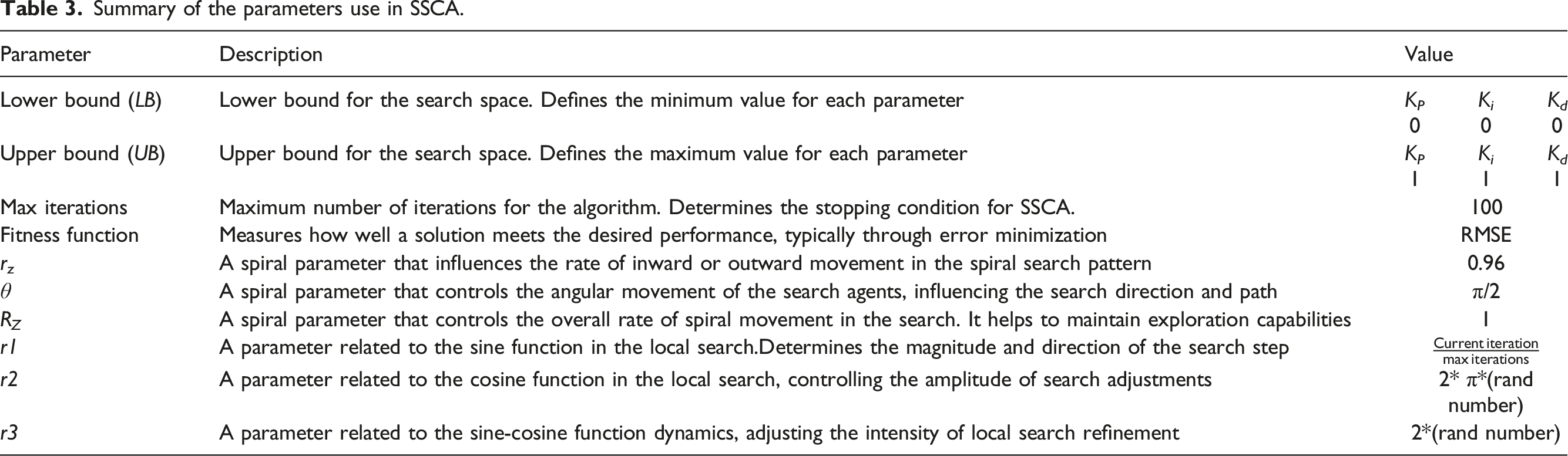
The Spiral Sine-Cosine Algorithm (SSCA) is an optimization technique that combines the Spiral Dynamic Algorithm (SDA) and the Sine-Cosine Algorithm (SCA) to balance exploration and exploitation during the search process. The SSCA begins by initializing a population of agents in the search space, each agent representing a potential solution. The algorithm first applies the spiral movement, which is described by the equation (2)
where xStar represents the center of the spiral,
After updating positions using the spiral equation, the algorithm further refines the agents’ positions using sine and cosine functions. The sine and cosine update equations (3) and (4)

where X(i) is the updated position of the current agent, r1 is adaptive step size that decrease over iteration,
These equations allow the agents to perform local searches around the best-known positions, enhancing the exploitation capability of the algorithm. By iterating these steps and updating the cost function values, the SSCA efficiently converges towards optimal solutions, making it effective for solving complex optimization problems.
Summary of the parameters use in SSCA.
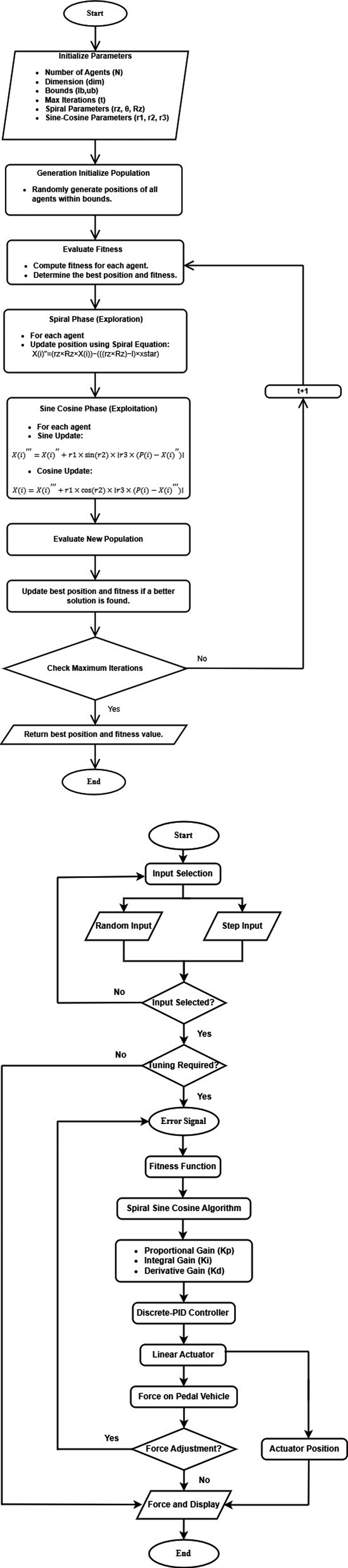
(a) Flowchart of spiral sine cosine algorithm. (b) Flowchart of PID gain tuning from SSCA.
Simulation setup
Figure 2 illustrates the block diagram of the simulation setup for the PID controller gain tuning using SSCA. The discrete PID controller is employed to regulate the system’s behavior by adjusting control actions based on the proportional, integral, and derivative terms of the error signal. This controller operates in a discrete-time framework, which is crucial for the simulation as it allows for precise adjustments and observations of system performance over time. Closed loop of the PID controller in a simulation system.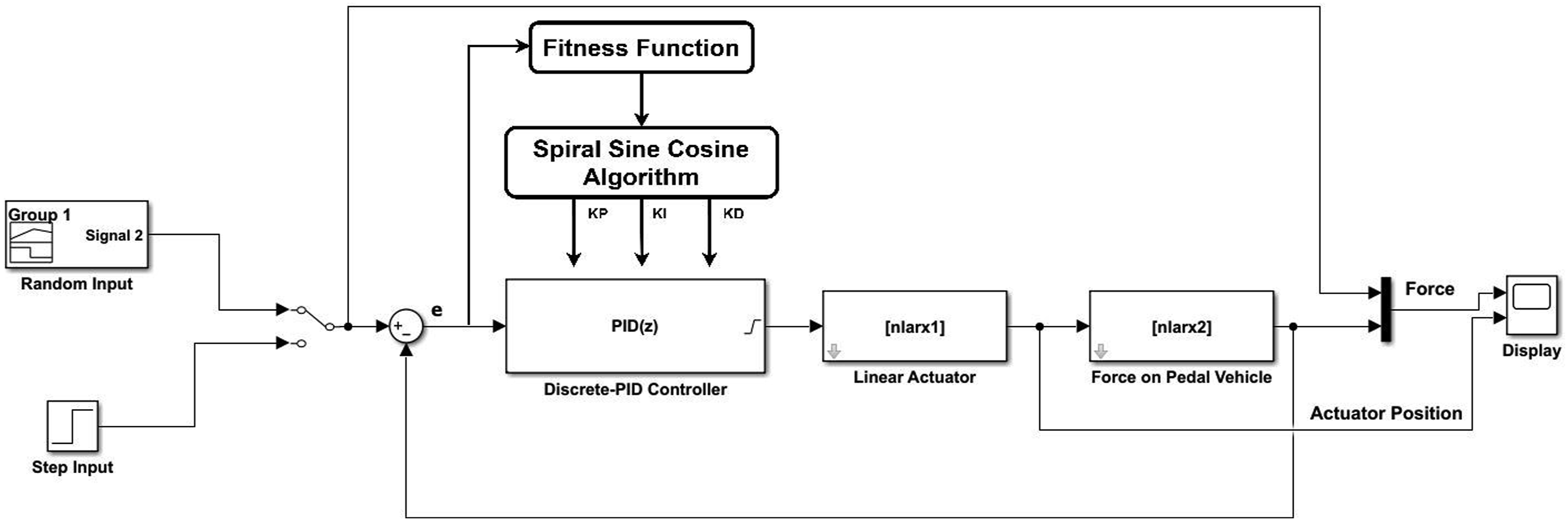
The actuator and force dynamics are modeled using NLARX models, which capture the nonlinear relationships between the inputs and outputs of these components. The NLARX model for the actuator describes how the control signals influence the actuator’s position, while the NLARX model for force characterizes the relationship between the actuator’s position and the resulting force applied in the system.
The simulation configuration uses a fixed-step size with the ODE4 (Runge–Kutta) solver. This setup ensures consistent and precise numerical integration throughout the simulation. A fixed step size of 0.1 seconds is chosen to balance computational efficiency with accuracy, providing detailed resolution of the system dynamics while maintaining manageable simulation times. The ODE4 solver, or the fourth-order Runge-Kutta method, is well-suited for this discrete-time simulation, offering robust performance in capturing the continuous dynamics of the system within the discrete framework.
Experimental setup: Hardware-in-the-loop (HIL) techniques
Matlab Simulink setup for HIL
Figure 3 illustrates the Hardware-in-the-Loop (HIL) setup in MATLAB, focusing on the interaction between the force actuator and the force sensor. In this setup, a random input signal is provided to the PID controller, which generates control signals to drive the actuator connected to the Arduino Mega via PWM pins 10 and 11. The actuator’s movement is controlled to apply force by pressing and depressing a force sensor. HIL system setup in Matlab Simulink.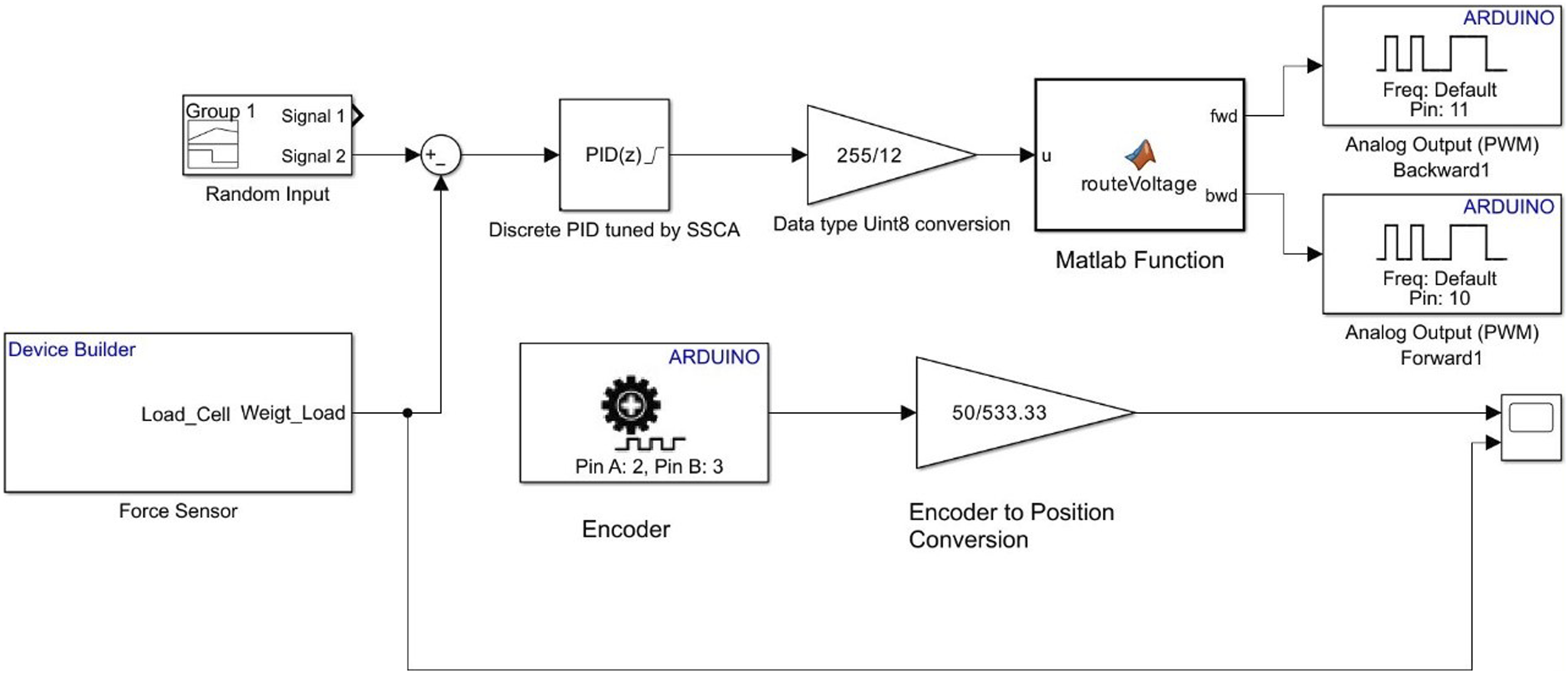
The actuator’s position is monitored using an encoder, which converts the actuator’s physical position into a measurable signal. As the actuator moves, it exerts pressure on the force sensor, which measures the applied force. This force value is continuously monitored and returned to MATLAB for real-time processing. The system is designed to stop the actuator’s movement once the desired force level is achieved, ensuring precise control and validation of the force application within the hardware setup.
Hardware-in-the-loop setup and overview of component use
Figure 4 illustrates the Hardware-in-the-Loop (HIL) setup, highlighting the configuration of the force sensor and linear actuator in relation to the pedal system. In this setup, the force sensor is mounted on the pedal, while the linear actuator is positioned in front of the pedal. The actuator mimics the motion of a leg by extending and retracting. When the actuator extends, it presses the pedal, exerting force on it, which is then measured by the force sensor. Conversely, when the actuator retracts, it depresses the pedal, resulting in a different force reading. This setup allows for the simulation of pedal dynamics and measurement of the force exerted on the pedal, providing valuable data for system analysis and control. HIL testing setup.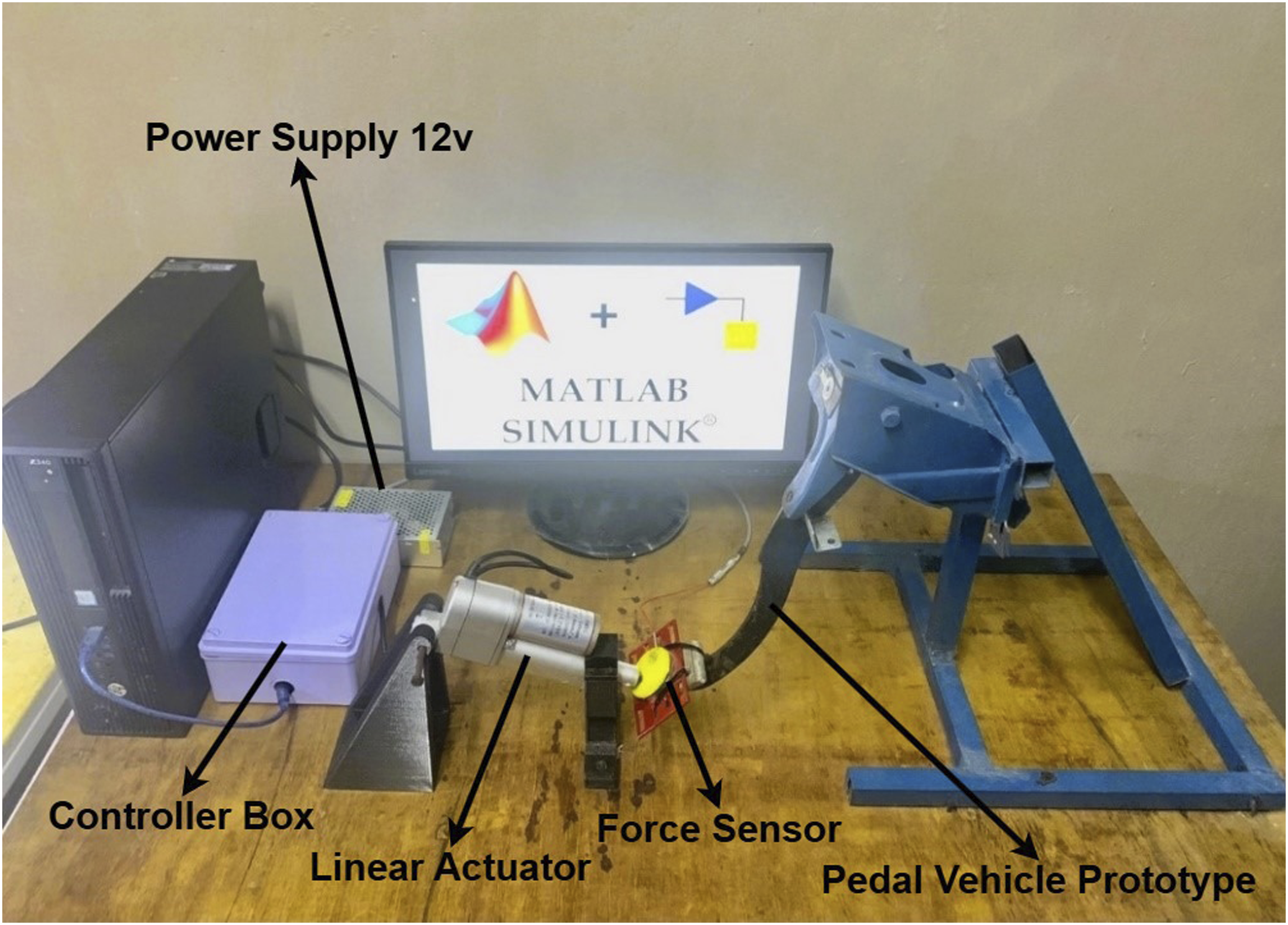
Figure 5 provides an overview of the block diagram to better visualize the HIL setup and the interactions between components, aiding in a comprehensive understanding of the system’s operation and integration. Overview of block diagram HIL testing setup.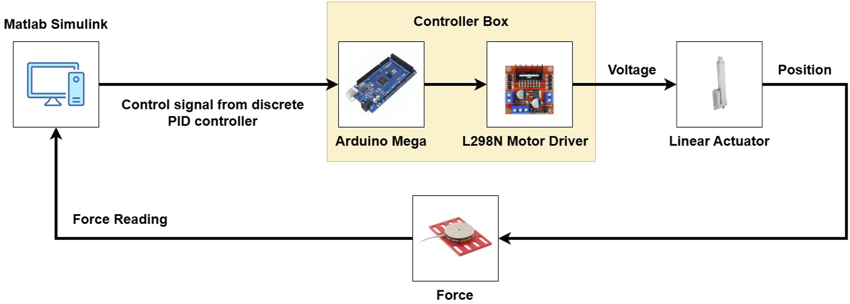
Linear actuator’s parameter.
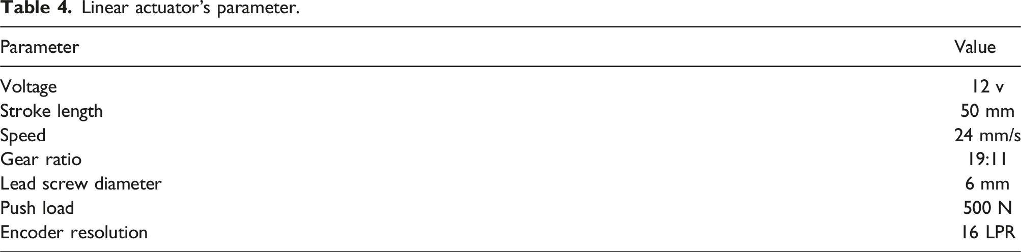
Furthermore, in this HIL setup, as discussed in the simulation, the numerical configuration is crucial for running MATLAB Simulink smoothly. Therefore, the setup configuration during both simulation and hardware testing remains consistent to ensure consistency and accuracy in the system’s performance evaluation. By maintaining identical parameters and settings across both simulation and hardware implementations, any discrepancies between simulated and real-world performance can be minimized, leading to more reliable and valid results.
Furthermore, in this Hardware-in-the-Loop (HIL) setup for automotive pedal systems, FUTEK Pedal Load Cell sensors, specifically the LAU200 model, have been utilized. These sensors are highly suitable for automotive testing and adhere to various industry standards. The high precision and reliability of the LAU200 load cell make it an excellent choice for accurately measuring pedal forces, which is crucial for ensuring the validity and consistency of experimental results. 29
As shown in Figure 6, the LAU200 load cell provides accurate and repeatable measurements of forces applied to the pedal, ensuring that the data collected is precise and reliable. This precision is essential for the development and validation of control algorithms used in the force feedback system. By integrating FUTEK Pedal Load Cell sensors into the HIL setup, it is possible to accurately capture the dynamic responses of the pedal under various input conditions, thereby enhancing the overall quality and robustness of the simulation and control system. FUTEK pedal LAU 200 load cell sensors.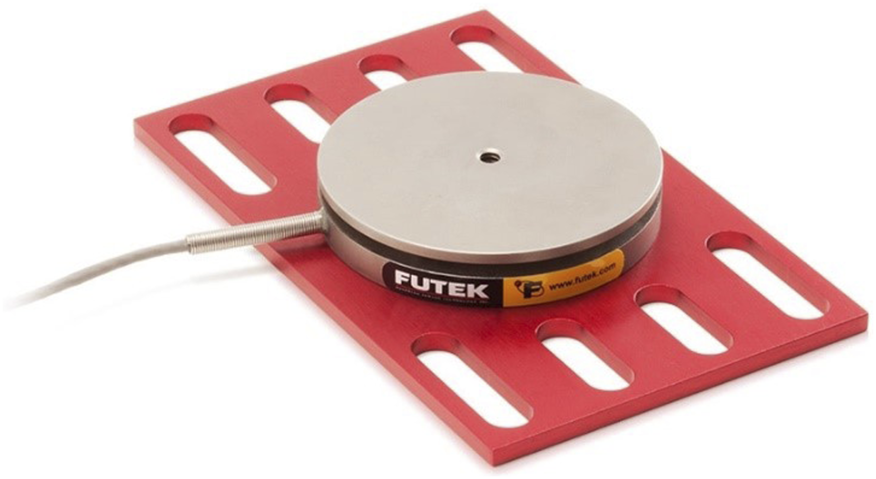
Additionally, compliance with industry standards ensures that data collected using the LAU200 sensors is credible and can be used for further analysis and development in automotive research. The high accuracy and durability of these sensors contribute significantly to achieving reliable and consistent results, which are critical for the success of developing advanced force feedback control systems for automotive applications.
Result and analysis
Selection of system dentification model
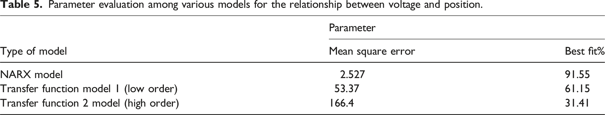
Parameter evaluation among various models for the relationship between voltage and position.
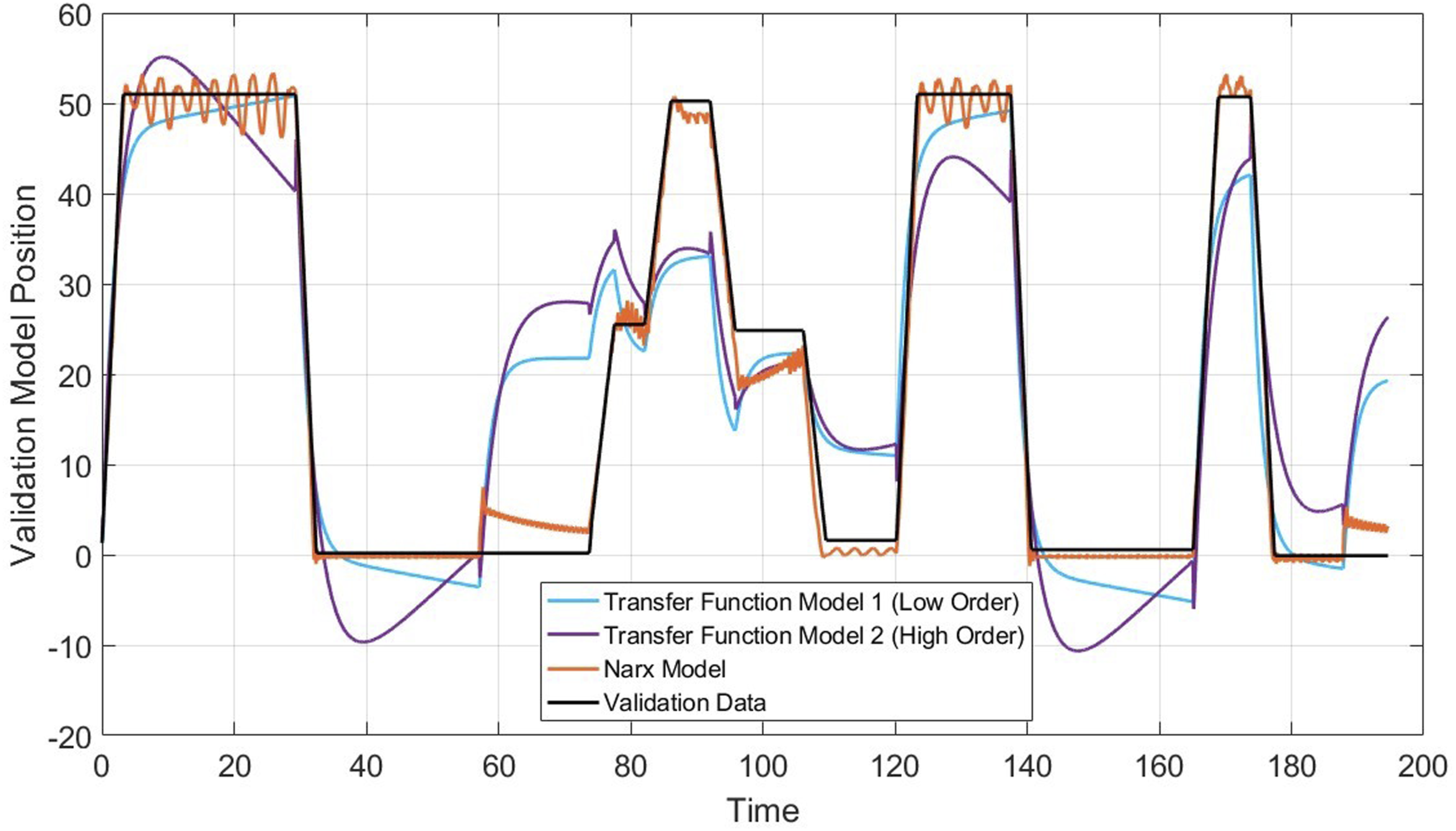
Validation testing for the relationship between voltage and position with various models.
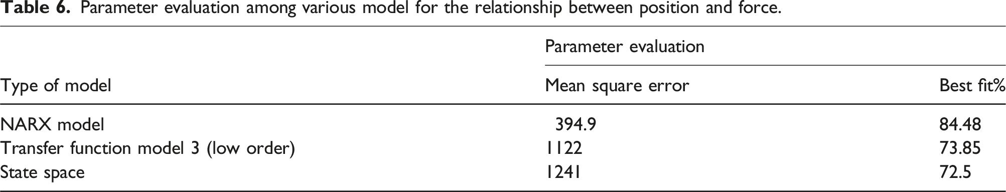
Parameter evaluation among various model for the relationship between position and force.
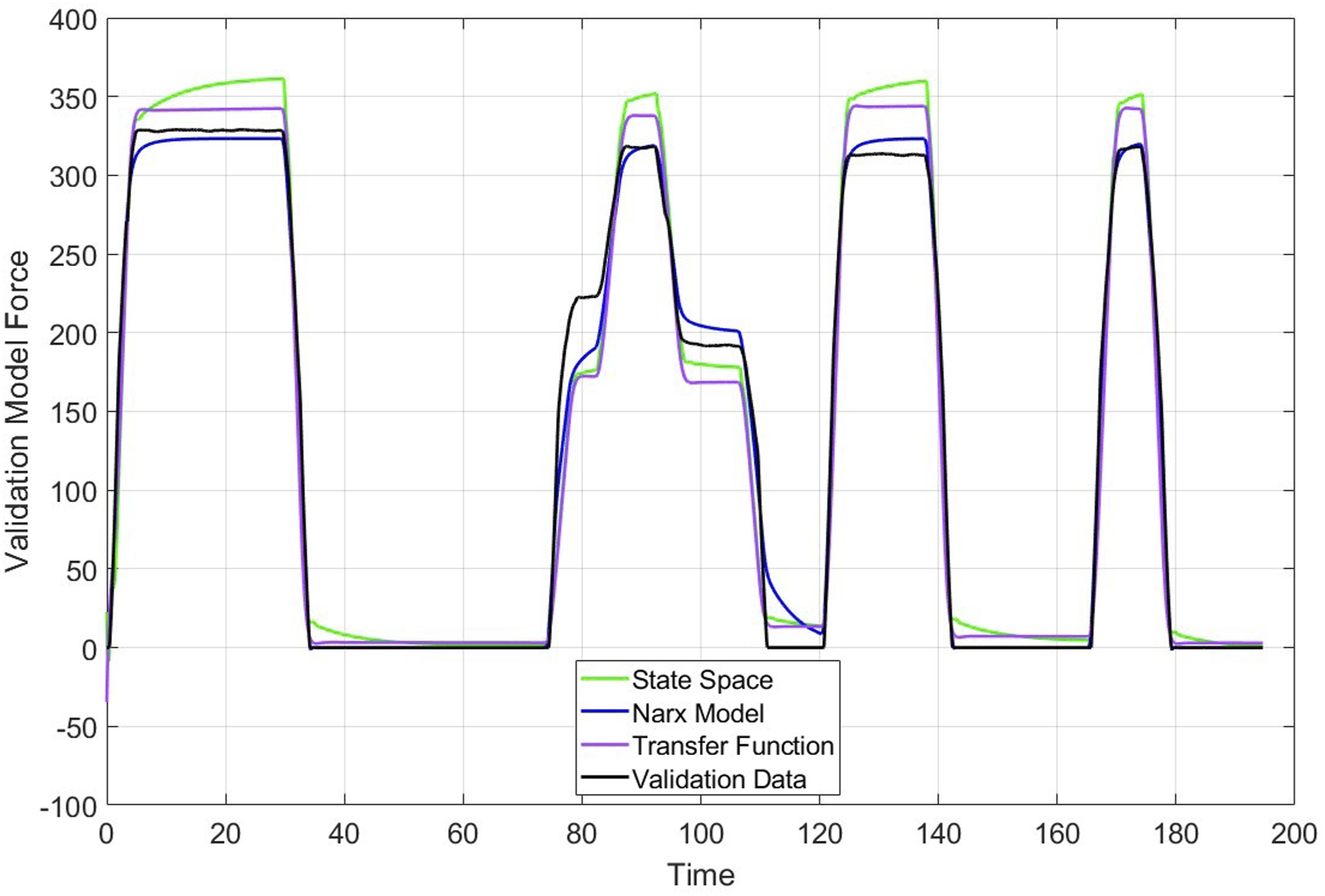
Validation testing for the relationship between position and force with various models.
Based on the evaluation metrics, the NARX model is clearly the most suitable choice for both the voltage-to-position and position-to-force relationships. Its ability to capture the nonlinear dynamics of the system with a high accuracy makes it the best model for our application. The lower Mean Square Error and higher Best Fit percentage reflect its superior performance compared to other model types evaluated. Therefore, the NARX model is selected for system identification in our force feedback control system, ensuring reliable and precise control for enhanced driver interaction and vehicle dynamics simulation.
Spiral sine cosine convergence analysis
Figure 9 shows the convergence plot generated by the Spiral Sine Cosine Algorithm (SSCA) over 100 iterations. This SSCA is designed to minimize error using the Root Mean Square Error (RMSE) as the cost function. The plot demonstrates the rapid convergence of the algorithm. Although the SSCA runs for 100 iterations, it converges within the first 15 iterations. Convergence plot by using spiral sine cosine algorithm.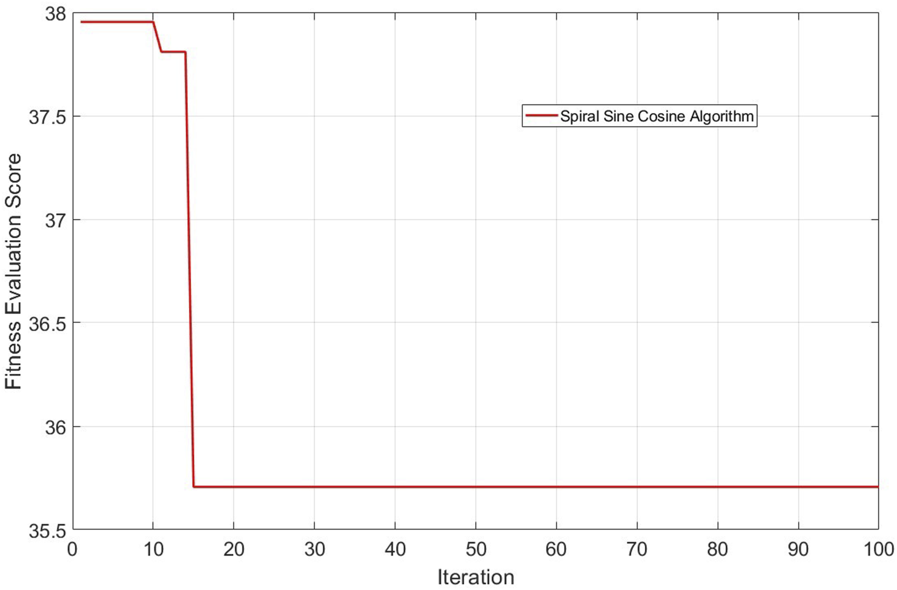
The key to this rapid convergence lies in the careful configuration of both the combination of spiral and sine cosine functions, as well as the SSCA algorithm parameters. The combination of these functions enhances the algorithm’s ability to explore and exploit the search space effectively, guiding it toward optimal solutions quickly. Additionally, the SSCA parameters are fine-tuned and restricted within ranges that consistently produce the lowest errors, directing the algorithm’s exploration towards promising regions. By focusing exploration within these predefined ranges, the algorithm avoids unnecessary exploration of less promising areas, thus speeding up convergence.
This rapid convergence not only saves significant time, especially during long iterations, but also maintains high result quality. This makes the algorithm suitable for scenarios where quick solutions are needed without compromising accuracy. The efficiency and effectiveness of the SSCA in minimizing RMSE demonstrate its potential for optimizing system identification models in force feedback control systems.
Simulation analysis
PID parameter tuned by SSCA.

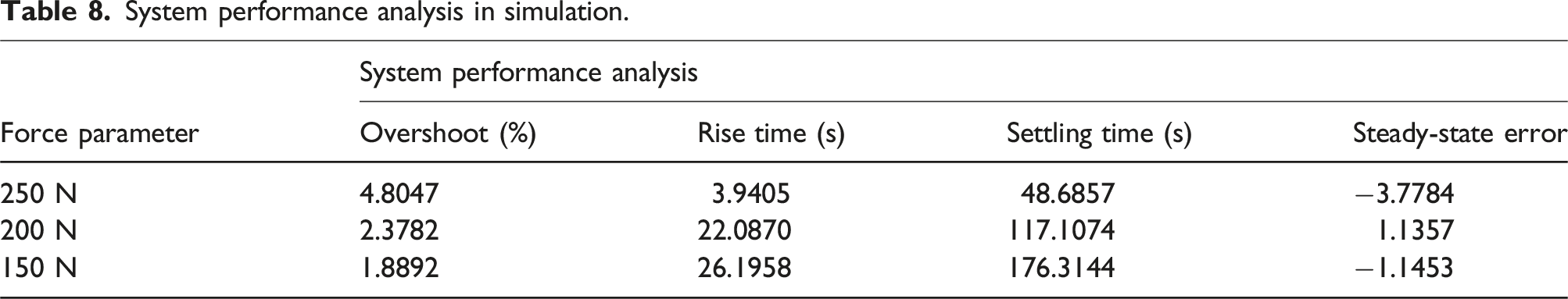
The system performance varies with different force parameters. For a 250 N force parameter, the system exhibits an overshoot of 4.8047%, a rise time of 3.9405 seconds, a settling time of 48.6857 seconds, and a steady-state error of −3.7784. As the force parameter decreases to 200 N and 150 N, the overshoot reduces to 2.3782% and 1.8892%, respectively. However, the rise time and settling time increase significantly, indicating a slower response. The steady-state error also varies, with positive and negative values suggesting slight deviations from the desired force output.
Despite the presence of noise and oscillations observed in Figure 10, the tuned PID parameters by the SSCA demonstrate that the system can achieve a balance between quick response and minimal overshoot. The performance metrics in Table 8 highlight the system’s ability to adapt to different force levels, maintaining acceptable levels of rise time, settling time, and steady-state error. Random signal testing in simulation. System performance analysis in simulation.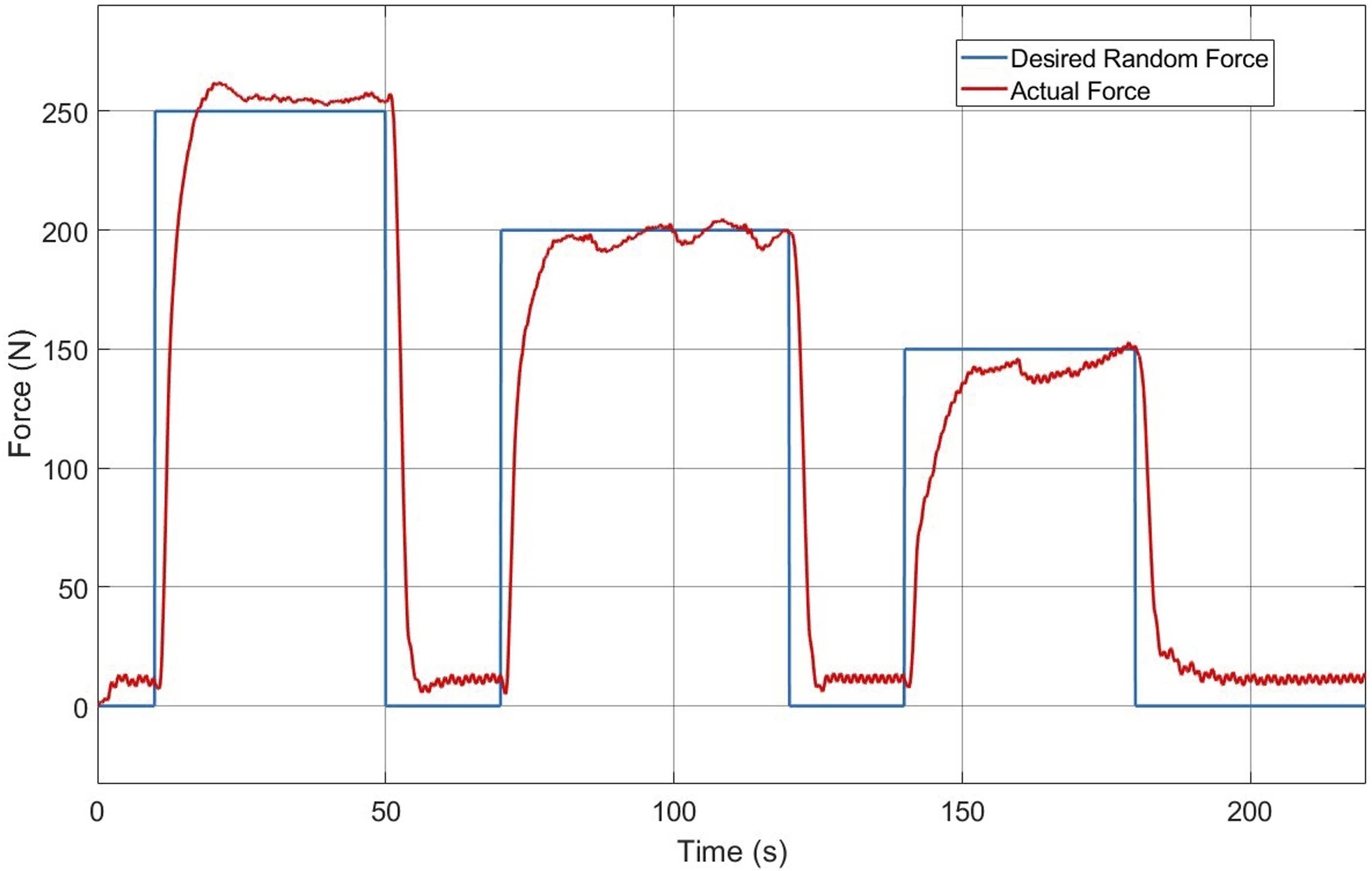
The analysis confirms the effectiveness of the SSCA-tuned PID controller in managing the dynamic response of the force feedback control system. The rapid convergence of the SSCA, as seen in the previous section, ensures that the PID parameters are optimized efficiently, resulting in a robust and reliable system performance.
Hardware-in-the-loop analysis
Table 7
Figure 11 illustrates the random signal testing in the HIL setup. Compared to the simulation results shown in Figure 10, there is a noticeable reduction in oscillation and noise. This improvement indicates that the HIL setup provides a more controlled and realistic environment for testing, which helps in minimizing the artifacts present in the simulation. Random signal testing in HIL setup.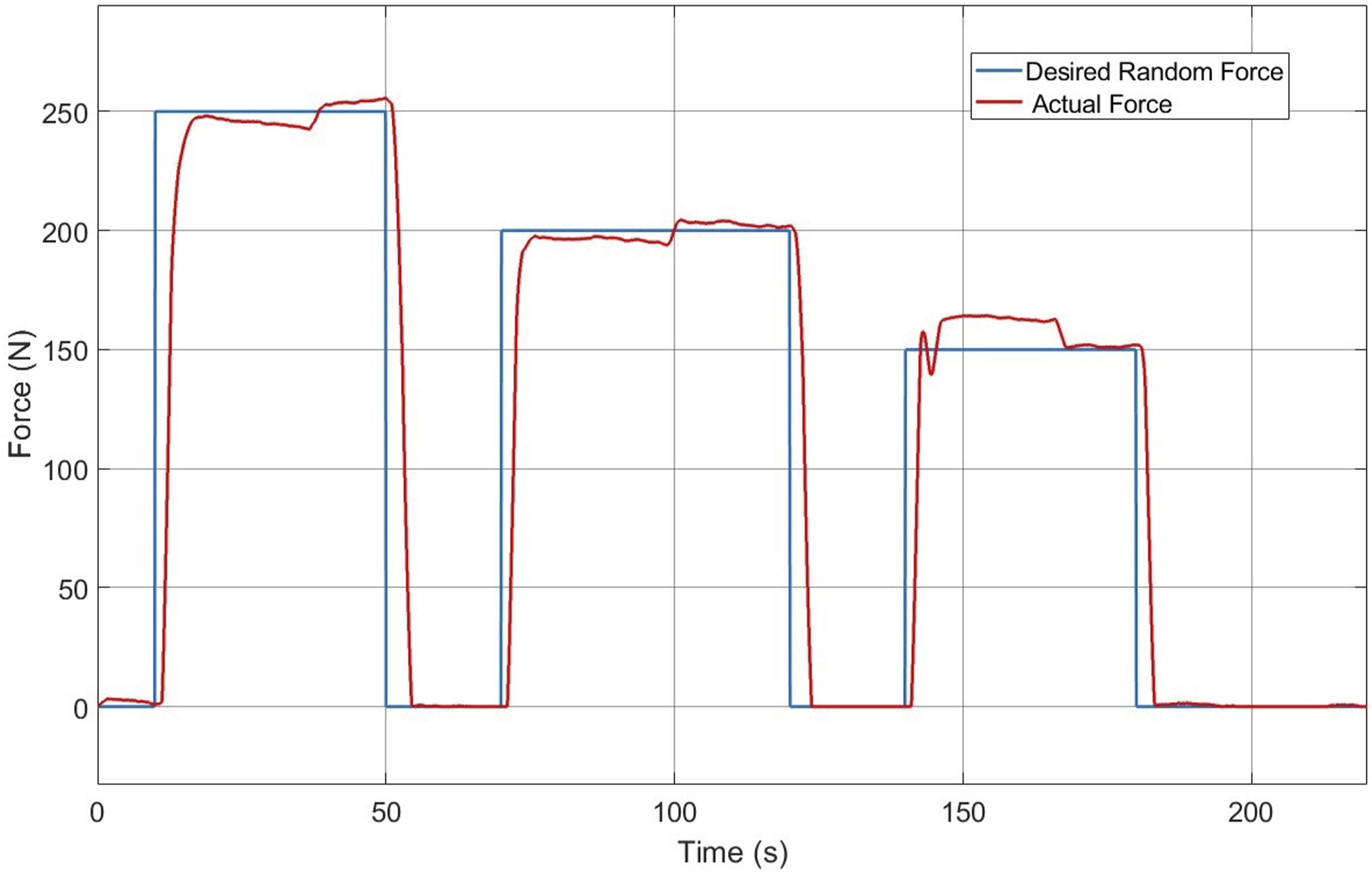
System performance analysis in HIL setup.
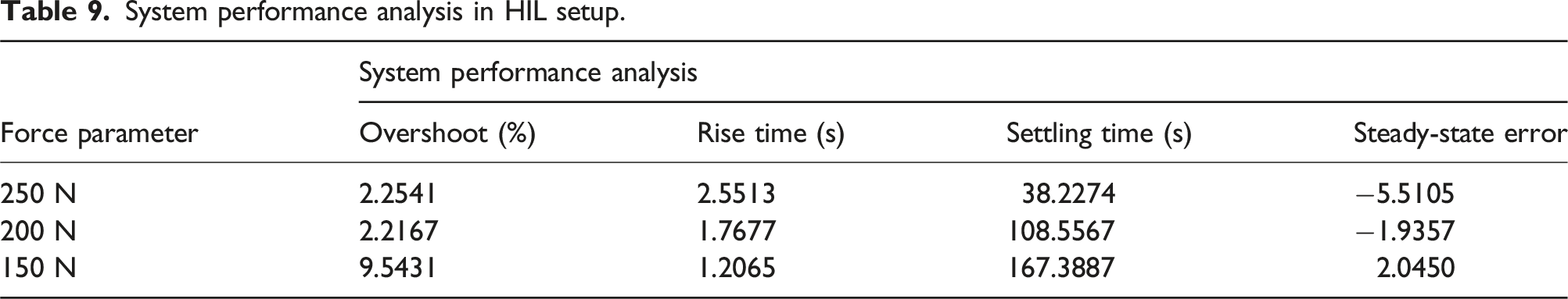
For the 200 N force parameter, the HIL testing results show a notable decrease in overshoot to 2.2167% from 2.3782% in the simulation. The rise time was significantly improved, dropping to 1.7677 seconds from 22.0870 seconds, which indicates a much faster response in the HIL setup. The settling time also decreased to 108.5567 seconds from 117.1074 seconds, highlighting a more efficient stabilization of the system. Furthermore, the steady-state error improved to −1.9357 from 1.1357, demonstrating a better accuracy in achieving the desired force output.
For the 150 N force parameter, there was an increase in overshoot to 9.5431% from 1.8892% observed in the simulation. Despite this increase, the rise time was dramatically reduced to 1.2065 seconds from 26.1958 seconds, and the settling time decreased to 167.3887 seconds from 176.3144 seconds. This indicates that while the overshoot is higher, the system achieves a faster and more efficient response in the HIL setup. The steady-state error changed to 2.0450 from −1.1453, reflecting slight deviations from the desired force output.
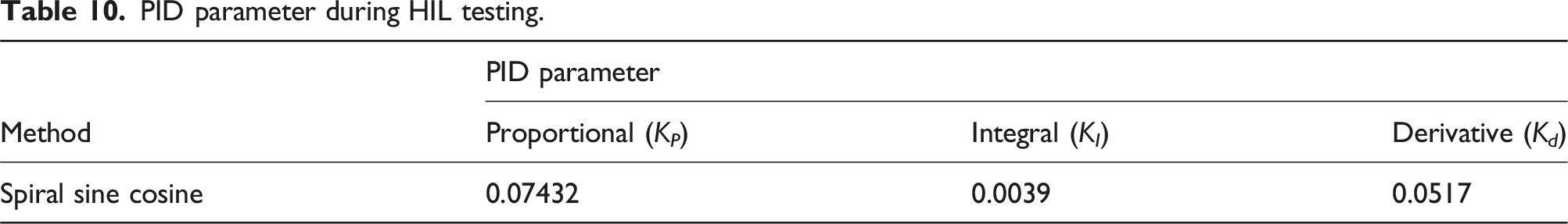
PID parameter during HIL testing.
Discussion
In real-world driving situations, particularly in automated pedal pressing systems, the trade-off between fast rise time and reduced overshoot is crucial for ensuring both performance and safety. A fast rise time allows the system to quickly respond to changes in input, such as when applying the brake or accelerating. This quick response is vital in urgent driving scenarios, where immediate action is required. However, a fast rise time can also result in overshoot, where the system temporarily exceeds the desired force or position before stabilizing. Excessive overshoot can reduce system stability, causing jerky movements that may lead to driver discomfort or loss of control. To mitigate this, reducing overshoot improves system stability by ensuring that the response stays closer to the desired target, resulting in a smoother and more predictable behavior. However, this often leads to a slower rise time, which can be detrimental in situations where rapid reactions are necessary. The Spiral Sine Cosine Algorithm (SSCA) was used to tune the PID parameters, balancing this trade-off by optimizing the Proportional (P), Integral (I), and Derivative (D) gains to achieve a system that responds quickly while minimizing overshoot. The results from the Hardware-in-the-Loop (HIL) testing, which involved applying the SSCA-tuned PID parameters, demonstrated significant improvements in both rise time and overshoot reduction. For example, the 250 N force parameter showed a reduction in overshoot from 4.8047% (simulation) to 2.2541% (HIL), while also improving rise time. These results confirm that SSCA can effectively optimize the controller parameters to balance fast response and system stability, ensuring a quick yet stable pedal pressing response in real-world driving conditions. This balance is essential for providing rapid reactions when necessary, while maintaining a smooth, stable driving experience.
Conclusion
In this study, a force feedback control system for automotive pedals was developed and validated using a PID controller optimized with the hybrid Spiral Sine-Cosine Algorithm (SSCA). The system’s performance was evaluated based on overshoot, rise time, settling time, and steady-state error, with comparisons made between simulation and Hardware-in-the-Loop (HIL) setups. System identification was employed to determine the most accurate model for representing the actuator and pedal force, resulting in Nonlinear Auto Regressive with Exogenous inputs (NARX) models effectively capturing the actuator and pedal force relationships, outperforming other models tested. The SSCA-tuned PID controller demonstrated improved performance in simulations, showing reduced overshoot and effective response across various force levels. The Hardware-in-the-Loop (HIL) setup further enhanced these results. For the 250 N force parameter, HIL reduced overshoot from 4.8047% to 2.2541%, improved rise time from 3.9405 seconds to 2.5513 seconds, and decreased settling time from 48.6857 seconds to 38.2274 seconds. For the 200 N force parameter, HIL lowered overshoot from 2.3782% to 2.2167%, significantly improved rise time from 22.0870 seconds to 1.7677 seconds, and reduced settling time from 117.1074 seconds to 108.5567 seconds, while enhancing the steady-state error from 1.1357 to −1.9357. Although overshoot increased for the 150 N force parameter from 1.8892% to 9.5431%, HIL markedly improved rise time from 26.1958 seconds to 1.2065 seconds and reduced settling time from 176.3144 seconds to 167.3887 seconds, with steady-state error changing from −1.1453 to 2.0450. Overall, the study demonstrates that integrating HIL testing with SSCA-tuned PID control significantly enhances the performance and accuracy of force feedback systems for automotive pedals. The HIL testing shows that the PID controller optimized with SSCA can be effectively implemented in real-life applications, particularly in force control pedal vehicles, thereby potentially reducing driver fatigue caused by repetitive actions of pressing and releasing the pedal. Future studies will shift to incorporating vehicle speed control, expanding the current system that regulates actuator and force applied to the pedal. The ultimate aim is to create a comprehensive control system that seamlessly integrates vehicle speed regulation with actuator and pedal force control. Moreover, other potential applications of SSCA-tuned PID control approach is highly adaptable and demonstrates robust optimization capabilities, making it suitable for a wide range of applications beyond the specific use case of force feedback control in automotive pedals. The versatility of this approach lies in its ability to balance precision and response time while minimizing errors, which is critical in dynamic and complex systems. This adaptability opens avenues for innovation, allowing the SSCA-tuned PID control approach to contribute significantly to advancements in technology across multiple domains include non-automotive industries like robots, prosthetics, or industrial automation, as well as other automotive subsystems like steering and suspension systems.
Footnotes
Declaration of conflicting interests
The author(s) declared no potential conflicts of interest with respect to the research, authorship, and/or publication of this article.
Funding
The author(s) disclosed receipt of the following financial support for the research, authorship, and/or publication of this article: This work has been financially supported by the Postgraduate Research Grant Scheme, PRGS with a university reference number (PGRS230341). This grant has been awarded by the Research and Innovation Department, Universiti Malaysia Pahang Al-Sultan Abdullah.