
Abstract
Extruded aluminium panels are a popular choice for architects and builders due to their lightweight, cost-effectiveness, design flexibility, superior weather resistance, and acoustic performance. Despite their popularity, there is a significant gap in research regarding their structural performance under wind-borne debris impact. Hence, a research project was established at Griffith University, Nathan campus, to examine experimentally, the response of extruded aluminium panels subjected to the impact of timber projectiles. The main aim of the current paper is to develop design guidelines for engineers to predict the response of extruded aluminium cladding panels exposed to windborne debris impact. This research extends our previous work on plain solid aluminium panels subjected to impact loading, where we developed and validated design guidelines. The continuation of this work into extruded panels enhances the practical toolkit available to engineers in mitigating impact-related failures in architectural applications. The experimental and numerical results showed four impact phases: the peak impact force phase, vibration, plateau and unloading phase. It was found that peak force was controlled by impact energy and contact stiffness, while plateau force is dependent on global stiffness and influenced by the plate thickness, width and boundary conditions Through parametric sensitivity studies, a comprehensive data bank was created, leading to the formulation of regression equations. These equations, validated against the numerical models, provide a reliable alternative to experimental testing for predicting peak impact force, plateau force, and maximum deflection, thereby improving the predictability and safety of using extruded aluminium panels in construction.
Introduction
Extruded aluminium panels have emerged as prominent materials in the global facade industry, establishing their dominance for various architectural applications. These panels have been used in some of the most iconic buildings around the world such as 71 Constitution, Aspen Village, and East Gateway due to their durability, aesthetic appeal, and longevity (Valmond & Gibson, 2023). To meet the architectural needs of each project, it serves as the perfect foundation for a wide range of finishing options (HVG Facades, 2023). This non-combustible substance gives architects full reign to design anything they choose, whether it’s a home, business, or industrial space (see Figure 1). Tropical cyclones, also known as hurricanes or typhoons, produce strong winds and heavy rainfall, posing a significant hazard to cladding systems. The violent precipitation and destructive winds caused by these storms endanger the safety of over a hundred million people daily (World Bank Group, 2017). Furthermore, the building’s façade system and envelope can be severely compromised by windborne debris that is generated by nearby plants, trees, and construction activities (Huang, 2018; STAFF, 2018). If the structure isn’t prepared to endure the enormous wind loads of a cyclone, this kind of damage might raise internal pressure to the point where the outside walls collapse (Hussain et al., 2021). Therefore, it is important to ensure the appropriateness of the design and the resilience of these cladding systems. Applications of extruded aluminium cladding systems (Blanchot; Gibson, 2023).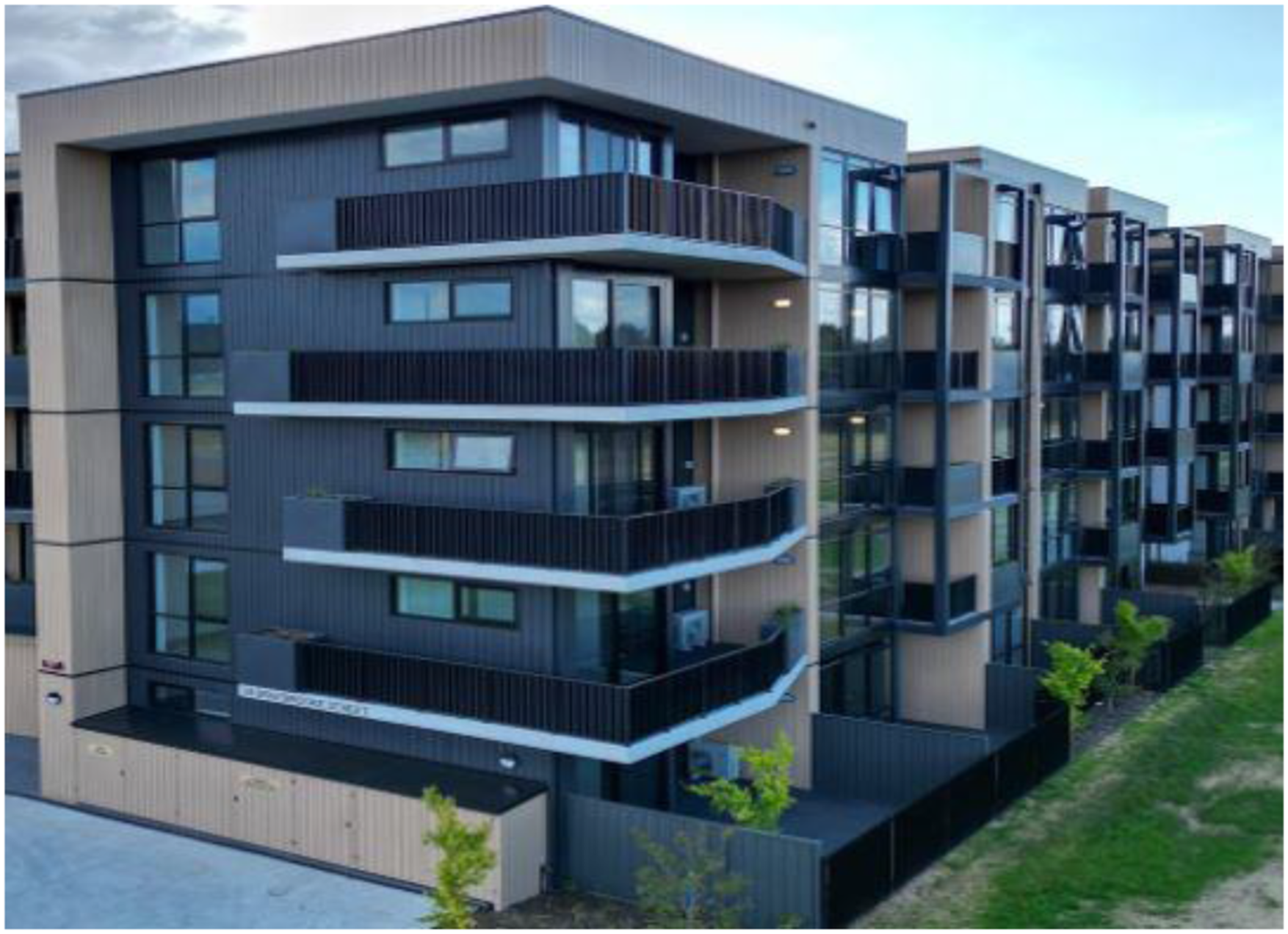
Over half a century ago, scientists and engineers embarked on a journey to explore the response of aluminium panels when exposed to wind-borne debris impact. (Calder and Goldsmith, 1971) conducted experiments on windborne debris impacting aluminium panels with 12.7 mm diameter steel projectiles at a velocity of 22.8 m/sec. The aluminium plates were 1.3 mm thick, simply supported and targeted at the centre. It was concluded that plastic deformation and perforation behaviour are influenced by impact velocity. Villavicencio et al. (2011) conducted a series of experimental tests on clamped aluminium plates struck at the centre by a mass with a spherical intender. The velocity range adopted was between 1 m/sec to 6 m/sec. It was found that at extremely low incident energies, no visible damage was observed in the plates. However, as the incident energy increased, the plates exhibited both indentation and global deformation (Shen, 1995; Sutherland and Soares, 2009; Villavicencio et al., 2012). Mohotti et al. (2013) studied the influence of the thickness of the plate on the deflection time history. A gas gun projectile launching system was utilized to launch a 37 mm diameter projectile at the centre of an aluminium plate measuring 300 × 300 mm. The velocities ranged from 9 to 14 m/sec. The experimental study concluded that the increase in thickness of the plates caused a reduction in maximum central deflection. Perera (2017b) used ice (simulating hail impact), timber, concrete, and brick specimens as projectiles and plain aluminium panel specimens as targets. An analytical model was developed aimed at predicting the contact force magnitude as a function of impact velocity, impactor mass, and the compressive stiffness of the impactor. The study was based on plain panels, however, in practice, the typical storm panel can be corrugated, trapezoidal, or square rib profile (Perera, 2017b). Further, only spherical projects were employed in the study. Pathirana et al. (2018) studied the damage to the aluminium facades by flying objects. The study used spherical projectiles made of wood and concrete, each 62.5 mm in diameter. Aluminium plates, measuring 300 × 300 mm and with thicknesses of 2 mm and 4 mm, composed of 5052-H34 alloy, were targeted at their centres with velocities of 21 and 40 m/s. An analytical model was developed for assessing the impact-induced damage to aluminium panels. It was found that impact action is dependent on both the material and structural dynamic behaviour of the projectile and the target. The study was based on spherical specimens as projectiles, and it was recommended to confirm the validity of the equations proposed for spherical by using non-spherical projectiles (Pathirana, 2018). It was further concluded that it is the type of material and shape of both the projectile and the target plate that plays a role in the response of the plates to the impact loading. Thus, an effort was made to explore the different shapes and materials of projectiles and the targets explored in the previous studies (Grytten et al., 2009; Gupta et al., 2008; Hussain et al., 2021; Mocian et al., 2018). It was found that the majority of the previous studies predominantly utilized steel as the projectile material, with variations in the shape of the projectiles. (Gupta et al., 2006) conducted experiments with both blunt- and hemispherical-nosed projectiles, (Iqbal et al., 2006) observed the impact of ogive-nosed projectiles, (Frye et al., 2009) examined the vulnerability of corrugated panels to spherical projectiles, (Perera, 2017a) investigated the impact of blunt projectiles, using ice and other materials, and (Pathirana, 2018) focused on spherical projectiles. However, just after cyclone Tracy, the impact testing criteria using roofing members was developed in Australia (AS/NZ1170.2_2021, 2021) that required external protective building facades to resist the impact of 50 × 100 mm timber blocks (Walker and Minor, 1980). None of these researchers has studied the impact of aluminium panels using 50 × 100 mm timber projectiles. Further, these studies (Frye et al., 2009; Gupta et al., 2006; Iqbal et al., 2006; Pathirana, 2018) have considered either plain aluminium metal sheets or corrugated metal sheets made of Zincalume, Aluminium, Zinc, Steel, etc., (Chen et al., 2014) as targets. The extruded aluminium panels, that offer design versatility, lightweight durability, corrosion resistance, and sustainability benefits, making them an excellent choice for various architectural have not been investigated yet.
In summary, existing research predominantly focuses on the aluminium metal sheet used as the target, neglecting investigations of extruded aluminium panels, which are more commonly used these days. None of the previous studies has examined the response of interlocked panels; rather, they are all centred around single panels. Furthermore, there is a lack of research in the existing literature that investigates the response of cladding panels to timber projectiles. A gap remains in identifying the key structural and load-related parameters that influence the behaviour of extruded aluminium cladding panel systems.
The primary objective of this paper is to develop design guidelines that engineers can utilize for designing extruded aluminium claddings subjected to wind-borne debris impacts. To achieve this goal, the enabling objectives are: (a) to develop a robust numerical model for extruded aluminium panels under impact loading, (b) to validate this numerical model using experimental results, and (c) to establish a comprehensive data bank through extensive parametric studies that evaluate critical structural and load-related parameters.
Experimental study
Test specimens
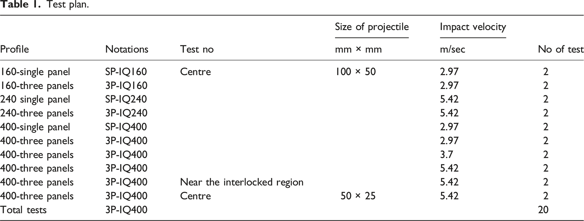
Test plan.
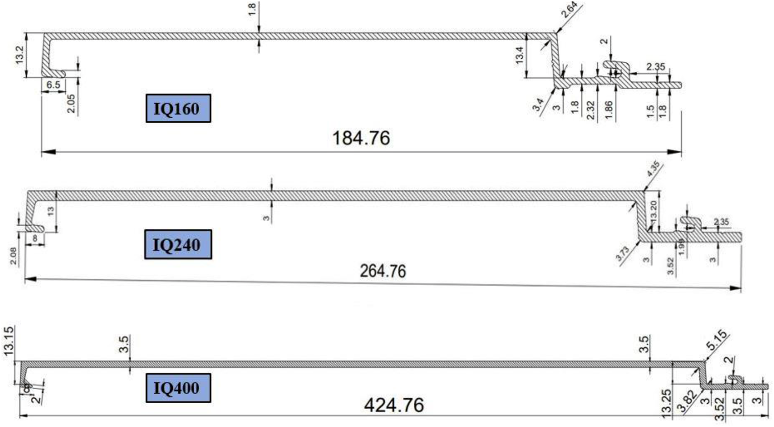
Profiles of extruded aluminium claddings investigated in this study.
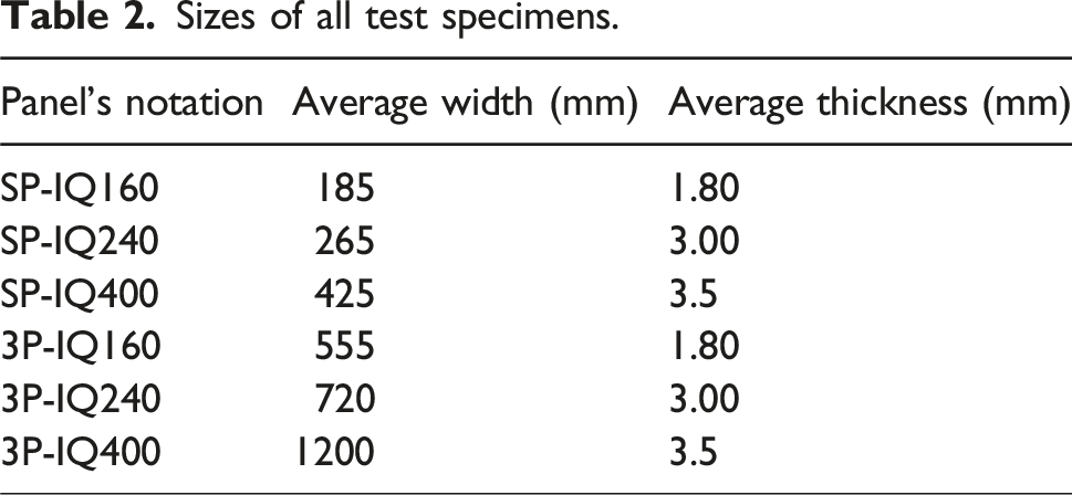
Sizes of all test specimens.
Material testing
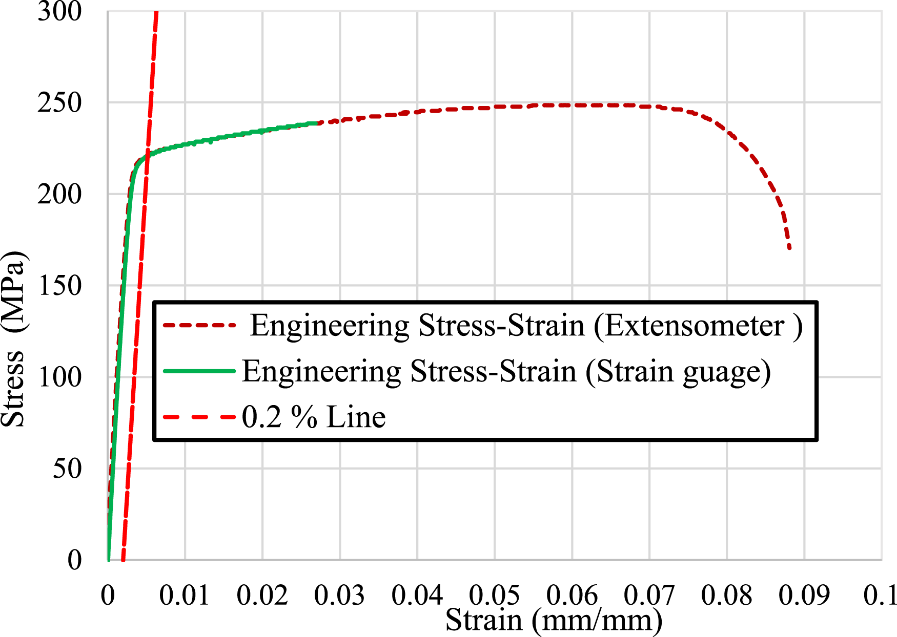
To assess the material properties of the specimen, two tensile coupons were performed per panel in accordance with AS1391 (Standard, 1991). The strain of the samples was measured using an extensometer strain gauge with a 50 mm gauge length, and resistance strain gauges attached to the centre of the samples (see Figure 3) for precise quantification within elastic range. To measure strain in the plastic region, both the Instron’s built-in displacement transducers and the extensometer were employed. This combined approach ensured a thorough assessment of strain across elastic and plastic regions of the samples. The coupon samples were tested at a constant rate of 0.01 mm/min using a 30 kN capacity INSTRON testing equipment. A typical stress versus strain curve obtained from the experiment is given in Figure 4. Uniaxial tensile test setup. Stress versus strain curve for 6063-T6.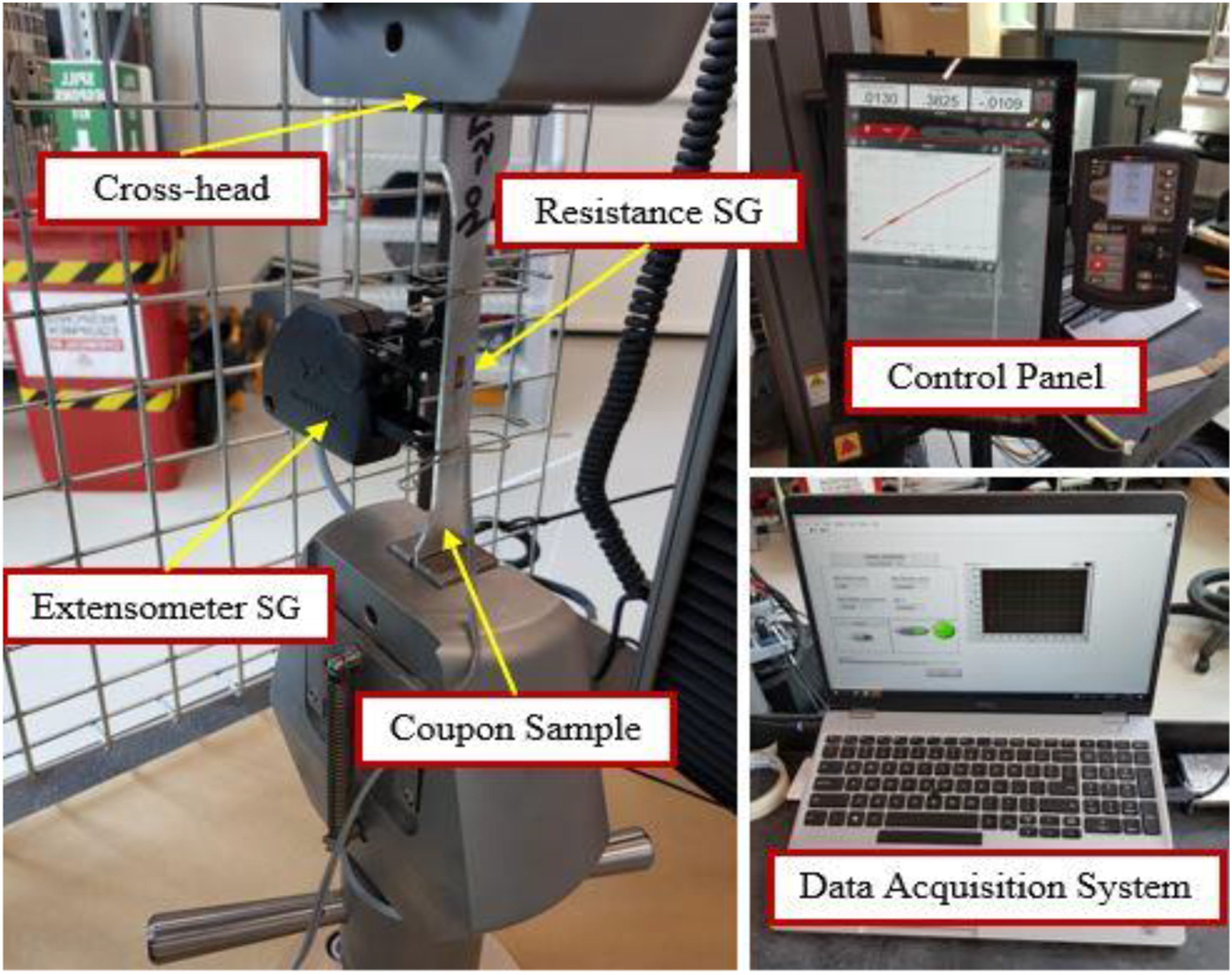
Setup and procedure
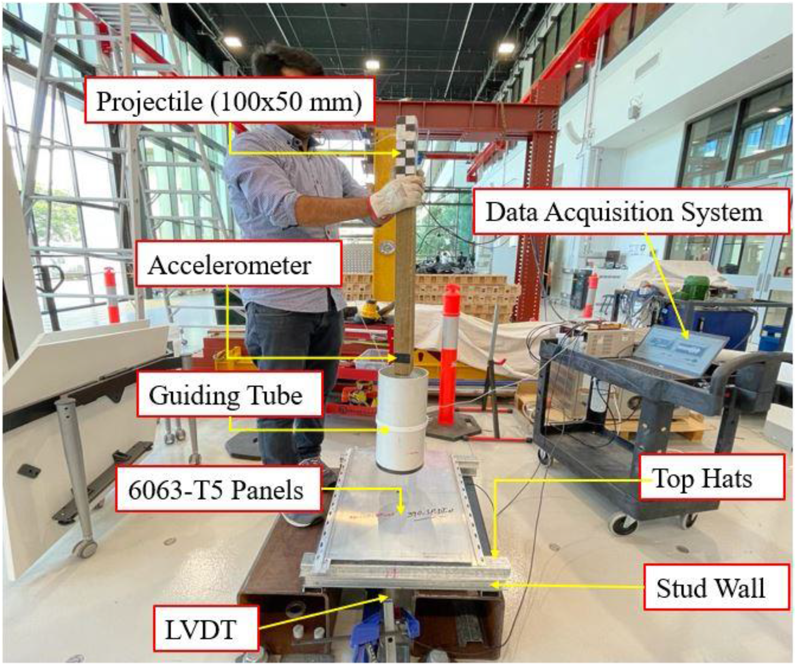
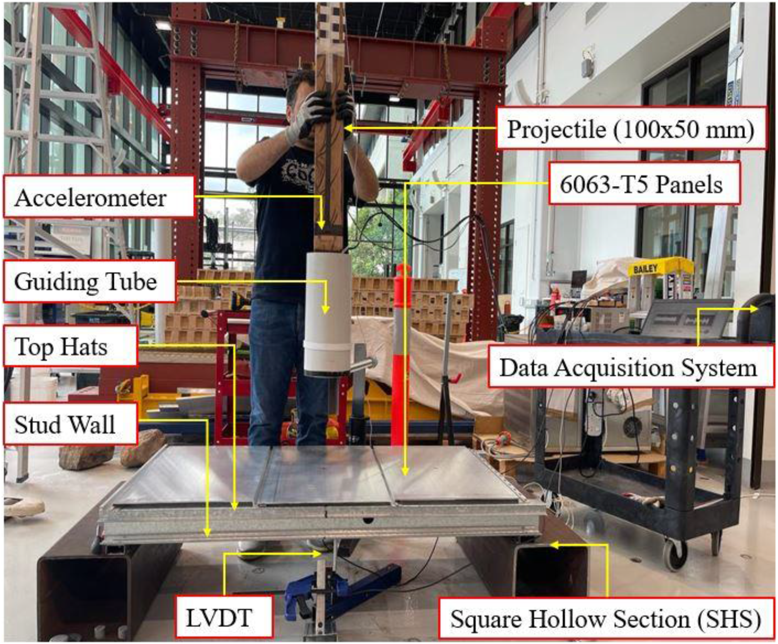
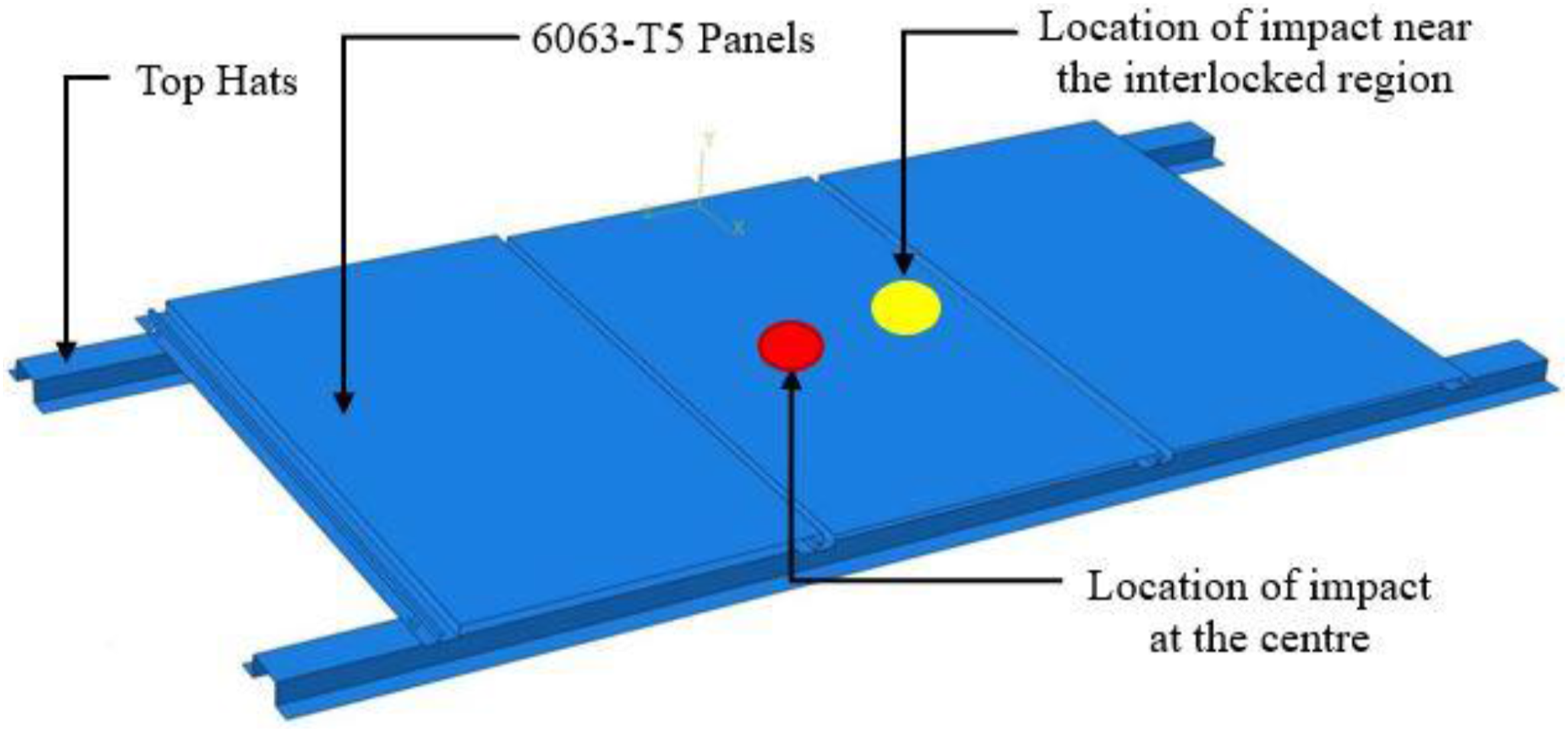
The test setup consisted of a drop pipe to guide the projectile to hit the extruded aluminium panels at the centre. The test specimens were made up of alloy 6063-T5 having different thicknesses and widths as given in Table 2. The panels were screwed to the 50 × 25 × 1.15 mm top hat battens. Top hats were supported by 90 × 35 × 1.15 mm stud steel framing. The complete cladding system was fixed by welding the stud walls to the square hollow sections (refer to Figures 5 and 6). Each type of panel was tested individually fixed using a starter panel with two repetitions of the test (refer to Figure 5). Then to find the influence of the interlocking on the response of the panels, the interlocked panels were also exposed to the drop test (refer to Figure 6) (AS/NZ1170.2, 2021). A seasoned timber, Messmate stringybark (Tasmanian oak), with a density of 780 kg/m3 was used as projectile (Wood.Solutions, 2023). The projectile’s mass was kept at 4 kg. To investigate the effect of the area of contact at the impact, a projectile with a quarter area (25 mm × 50 mm) was also employed in the experimental study (see Figure 7). The different locations of impact (please refer to Figure 8), velocities of impact and areas of contact at the impact employed in this experimental study are given in Table 1. The drop velocities were calculated using equation (1), where V is the velocity of impact (m/sec), g is the gravitational acceleration (m/sec2), and h is the drop height (m). Single panel subjected to low velocity of impact. Interlocked panels subjected to low velocity of impact. Projectiles and high-speed cameras employed in the experimental study. Different locations of impact considered in the study.
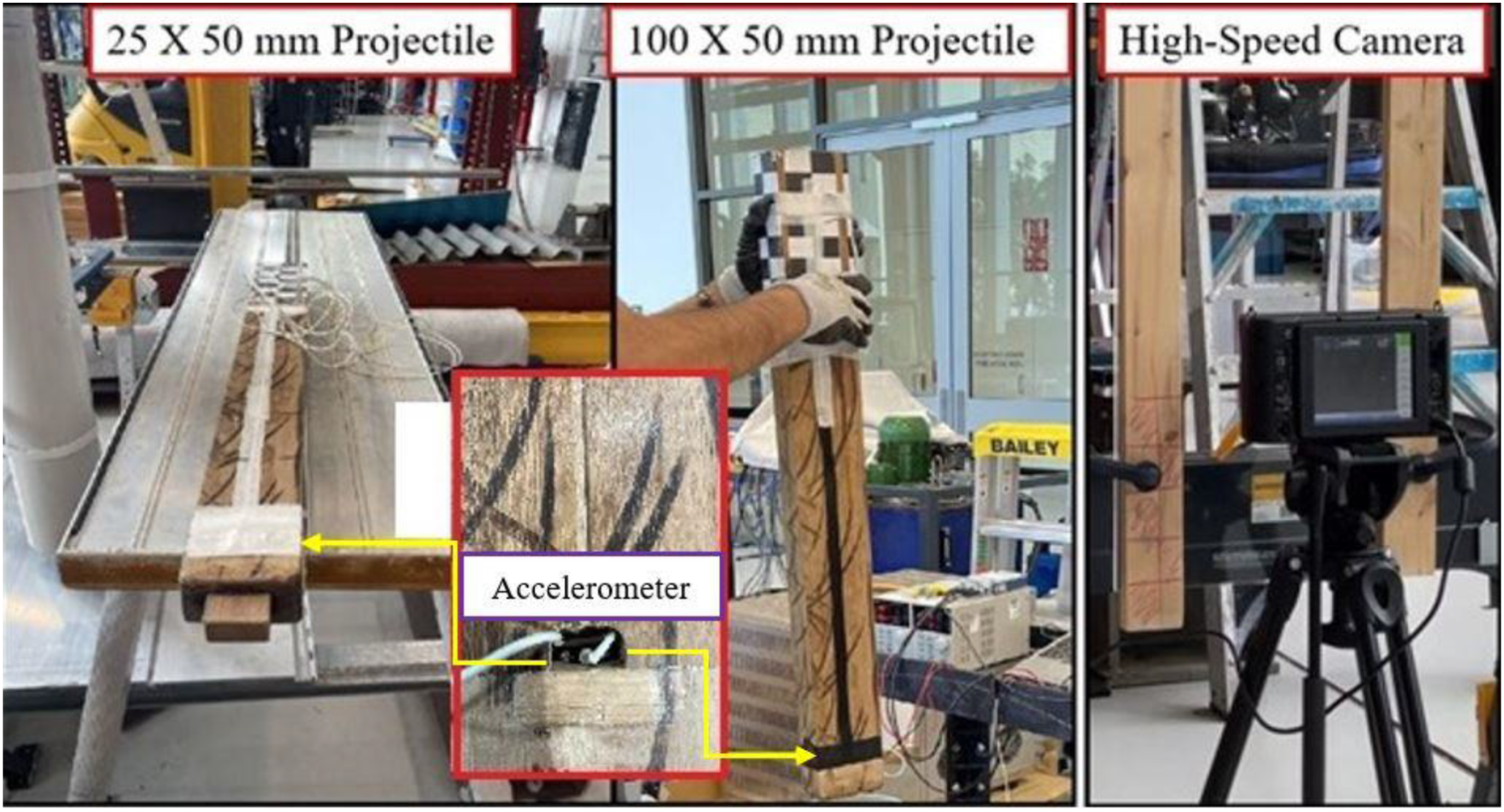
To address concerns regarding pipe friction and air resistance impacting velocity measurements, we employed a High Frame Rate (2154 FPS), High Definition (1920 × 1280) Portable Laboratory and Field Imaging System, utilizing the Mega Speed X9 PRO (refer to Figure 7), for multiple tests to verify the calculated drop velocity. Given the moderate drop height and a pipe diameter slightly larger than that of the projectile, careful observation revealed that the influence of air pressure and friction on velocity was negligible.
Instrumentation
A laser displacement sensor, HG-C 100, was placed beneath the panel and aligned with the vertical axis of the projectile’s motion to capture the deflection-time history of the specimen during the impact test. The HG-C1100 sensor offers a measuring range of ±35 mm and a sampling rate of 26 K/sec. Additionally, an accelerometer (7264D-2KTZ-2-360, 2,000 g, with a resonance frequency of 40 kHz) was installed on the projectile, 50 mm from the striking edge, to measure its acceleration during impact. As shown in Figure 7, the accelerometer was embedded in the timber, perpendicular to the drop direction, to record the acceleration-time history, which was then used to determine the impact force-time history using newton second law of motion.
Results and discussions
Figure 9 illustrates the force-time history for a single panel (IQ160) subjected to an impact by a timber projectile at a velocity of 2.97 m/sec. The timeline of the impact can be divided into four distinct phases: initial peak, vibration, plateau, and unloading. The first three stages—initial peak, vibration, and plateau—occur during the contact period of the impact, while the unloading phase transpires during the separation stage. At the onset of impact, the force rapidly escalates to its highest point, followed by subsequent smaller fluctuations. During the plateau phase, the panel and impactor remain in sustained contact, moving together. This phase transitions into the unloading stage, where the force gradually reduces to zero as the panel and impactor fully separate. Force-time history of a single panel exposed to the impact of timber (V = 2.97 m/sec).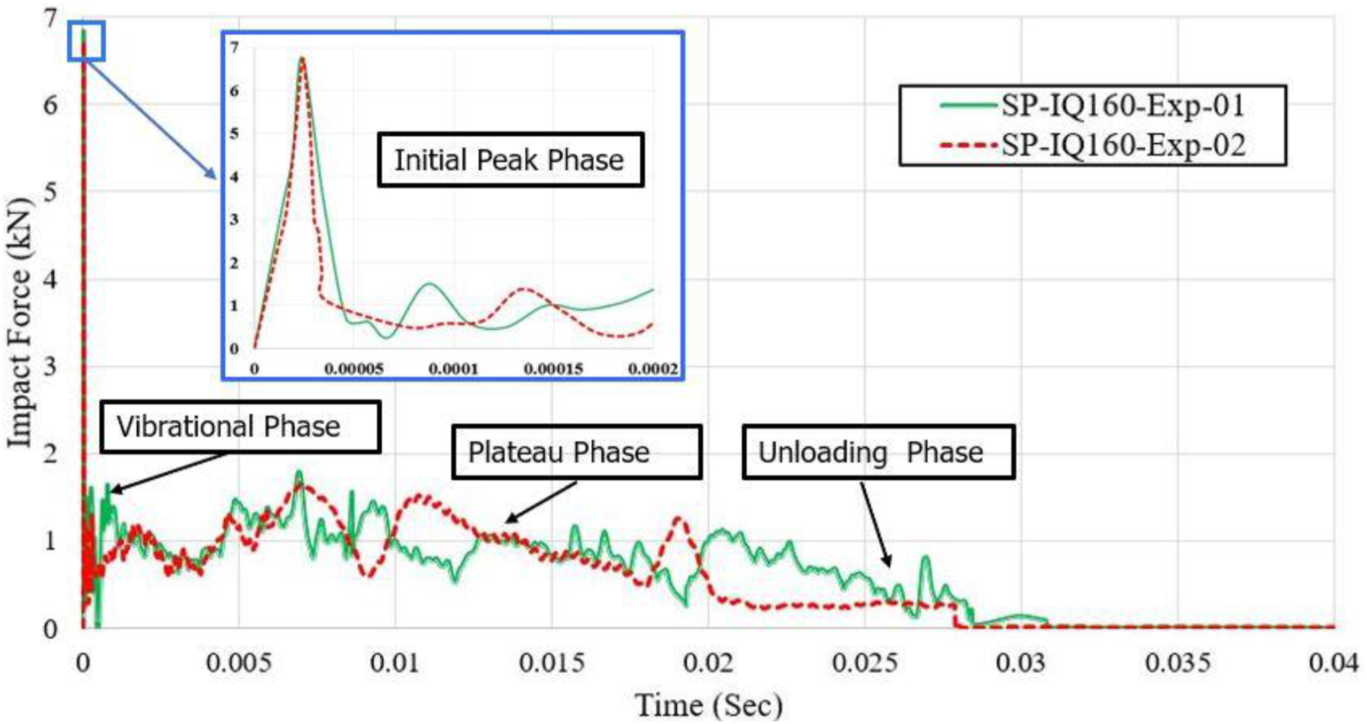
Initial peak force
Influence of interlocking of panels on peak force
Experimental results of initial peak force.
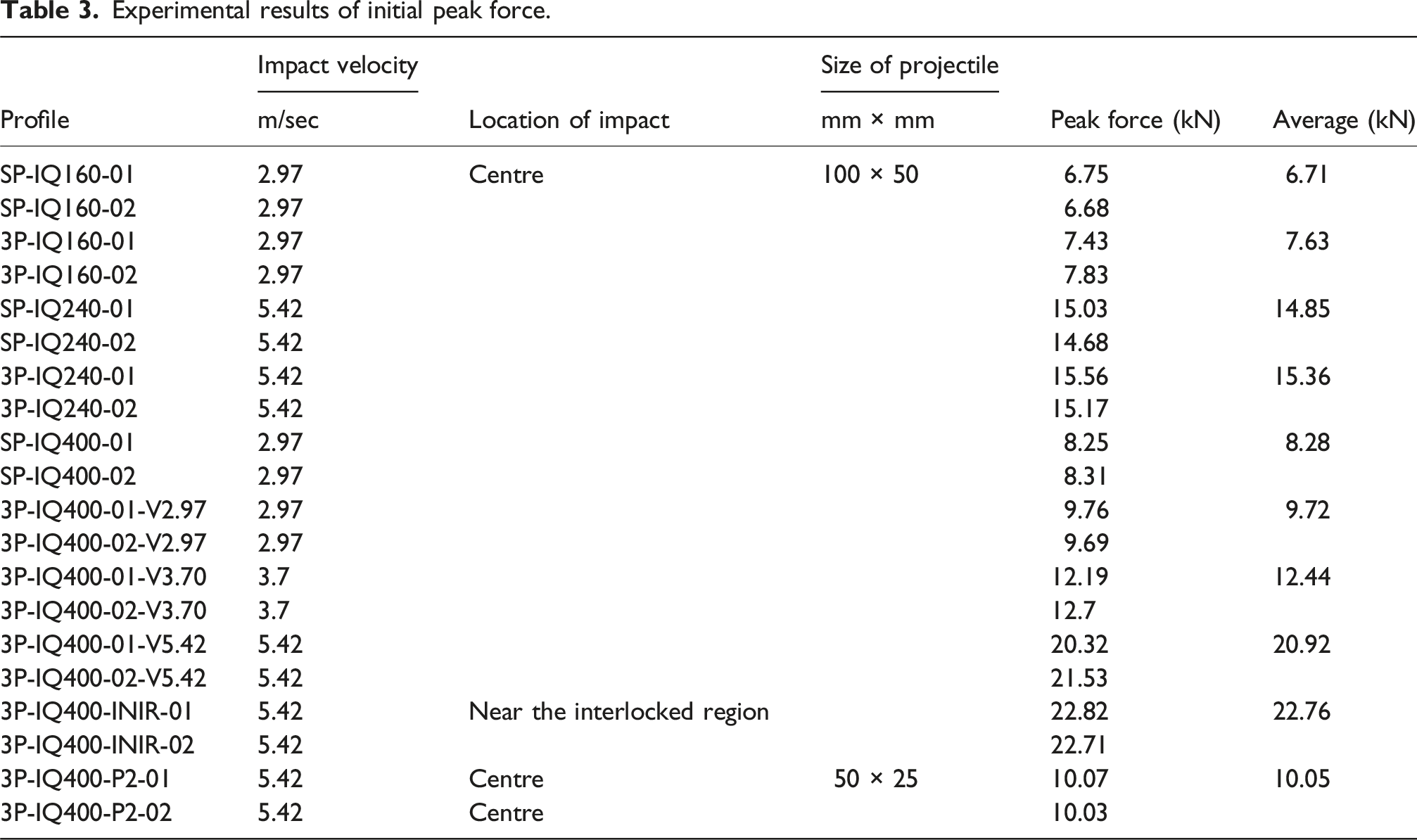
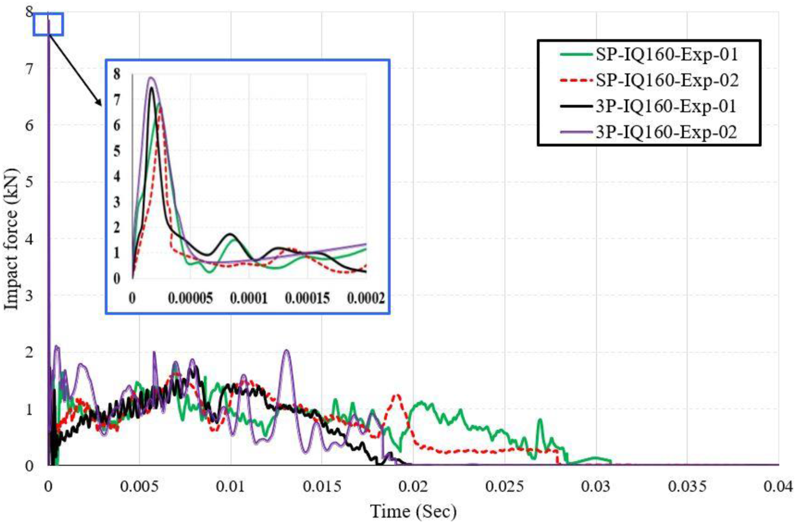
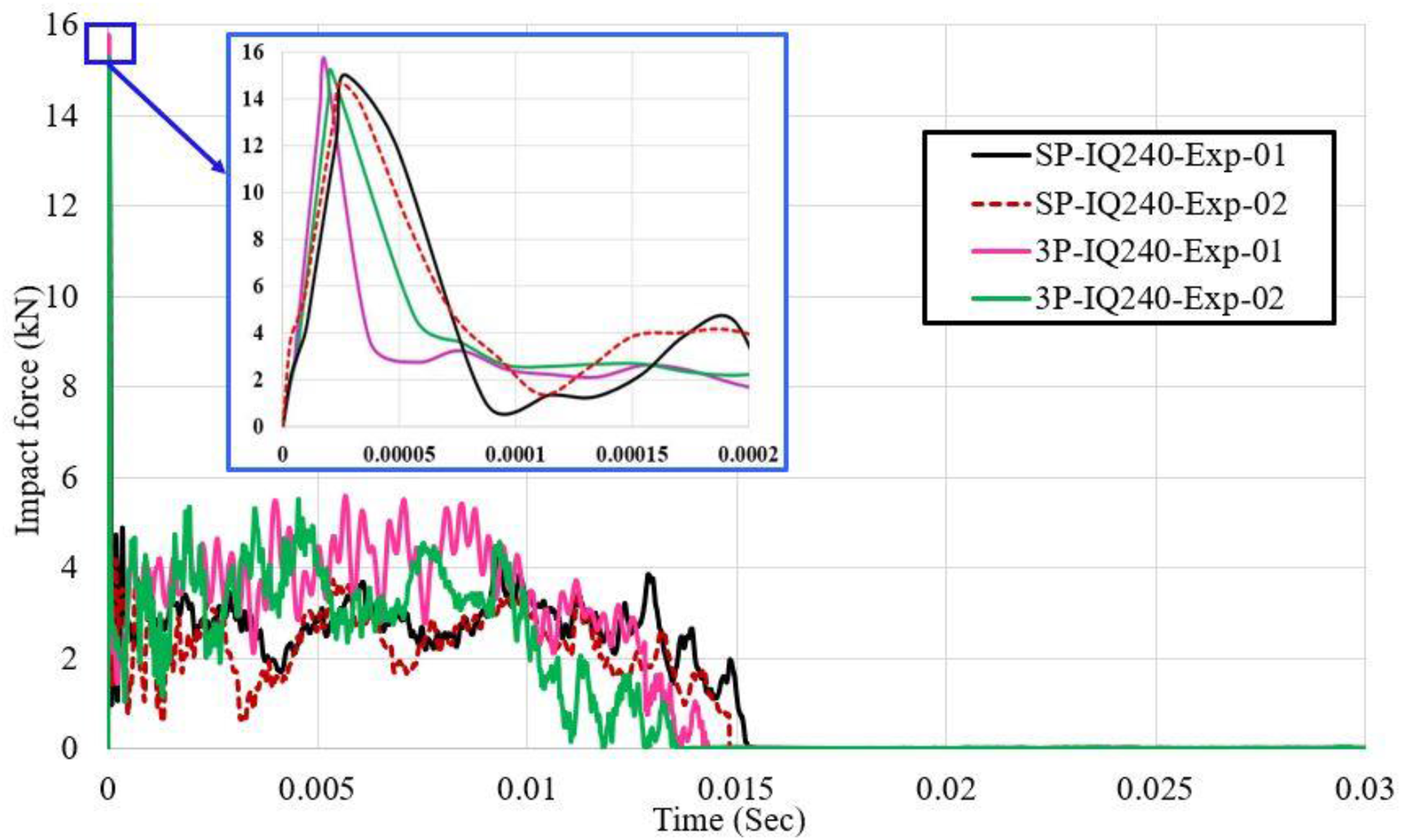
An average value of 6.71 kN was recorded when a single panel IQ160 was subjected to the impact of a projectile dropped at a velocity of 2.97 m/s, targeting the centre of the panel. However, when interlocked panels IQ160 were subjected to the same velocity and location of impact, the force increased to 7.63 kN (refer to Figure 10). This indicates that interlocking the panels amplified the initial peak force by about 13.71%. Likewise, for IQ 400 panels targeted at the centre with an impact velocity of 2.97 m/s, the force increased by 17.39% (refer to Table 3). This increase was around 3.4% for IQ240 exposed to the impact at 5.42 m/sec (see Figure 11). It was found that interlocking the panels leads to an increase in the overall stiffness of the cladding system. This increased stiffness affects the contact stiffness ke and the response to an impact force (refer to equation (2)). Force-time history for single and interlocked panels (IQ160) (V = 2.97 m/sec). Force-time history for single and interlocked panels (IQ240) (V = 5.42 m/sec).
Influence of the location of impact on peak force
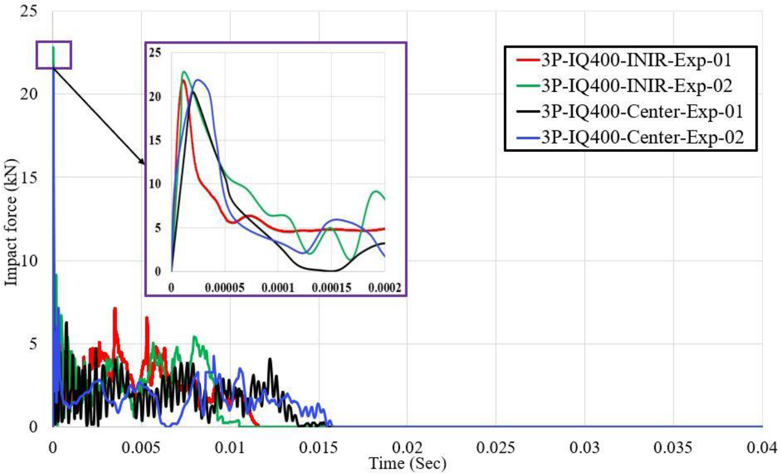
The study examined the influence of the location of impact on the response of the extruded panels by subjecting them to impacts at both the centre and in close proximity (within 5%) to the interlocking region. At a velocity of 5.42 m/sec, the average value of the initial peak impact force recorded when targeting the IQ 400 panels at the centre was 20.92 kN (refer to Table 3), but it increased to 22.76 kN when the impact occurred near the interlocking area (see Figure 12). This represents an approximate 8.8% increase in impact force. This increase is attributed to the greater stiffness of the panel near the interlocking region. Thus, when the projectile strikes this area, the higher contact stiffness (ke) leads to a greater initial peak impact force (refer to Figure 13) Location of impact close to the interlocked region (V = 5.42 m/sec). Force-time history of panels impacted near the interlocked region at a velocity of 5.42 m/sec.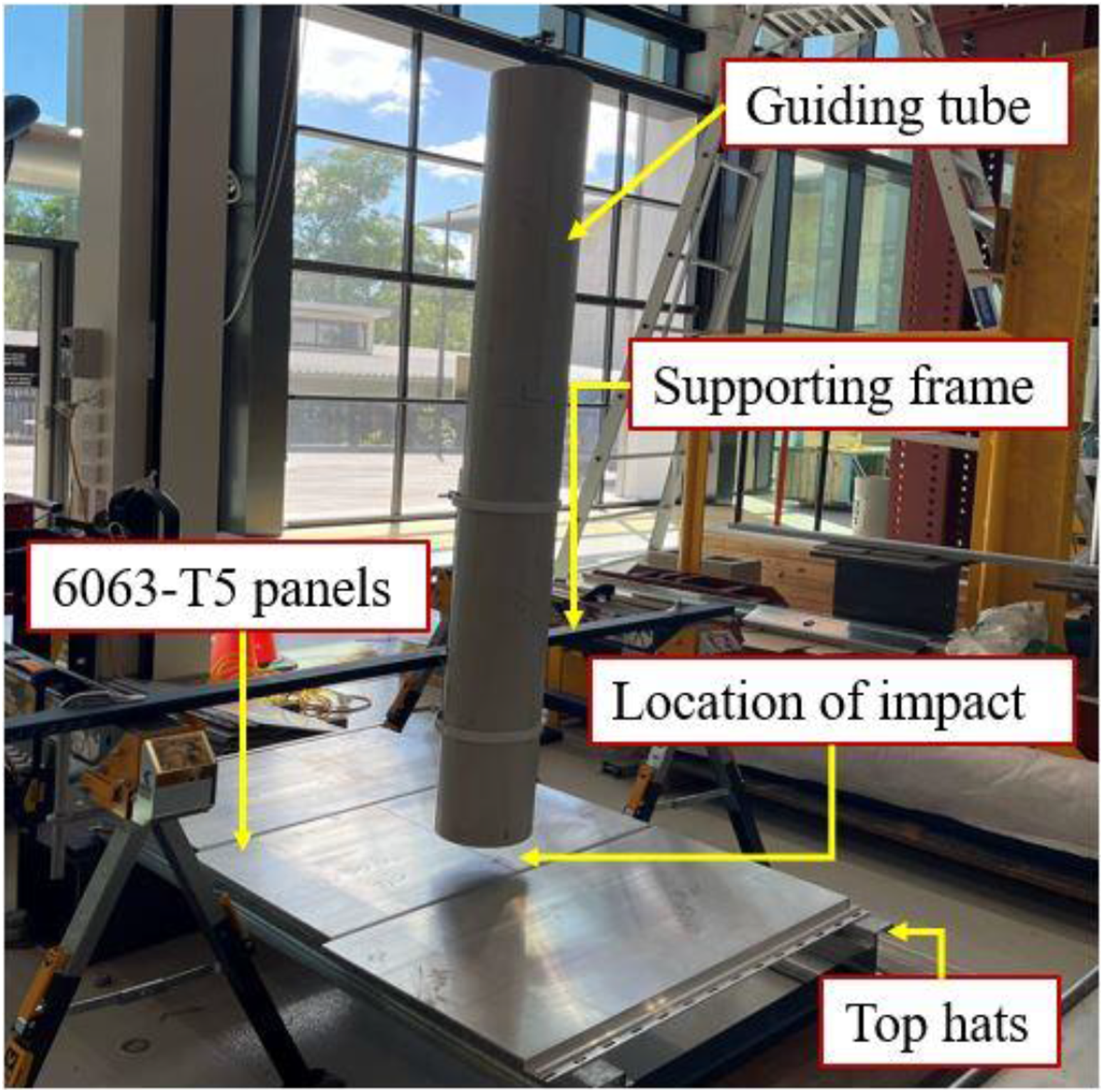
Influence of the area of contact at the impact on peak impact force
The contact area refers to the region where the impactor (in this case, a drop weight with rectangular geometry) comes into contact with the extruded aluminium claddings. The area of contact during impact significantly influences the peak impact force. When the IQ 400 interlocked panels were exposed to the impact of a 100 mm × 50 mm projectile at a velocity of 5.42 m/sec, a value of 20.92 kN was recorded. This value dropped by 51.9% to 10.05 kN by employing a 25 mm × 50 mm projectile (refer to Figure 7) targeting the extruded aluminium panels at the same location with the same velocity (see Figure 14). The impact force dropped because when the area of contact is larger, the force is distributed more evenly, leading to a stronger initial impact. Further, the smaller the impact area, the projectile’s force is concentrated over a smaller target surface, potentially causing local deformation and material failure, thereby decreasing the impact force. These findings align with the research conducted by (Li et al., 2019) in their study on the influence of drop-weight geometry and interlayer on impact behaviour, indicating that larger curvature radii of drop-weight heads result in increased impact forces. Force-time history for IQ 400 exposed to projectiles with different areas (V = 5.42 m/sec).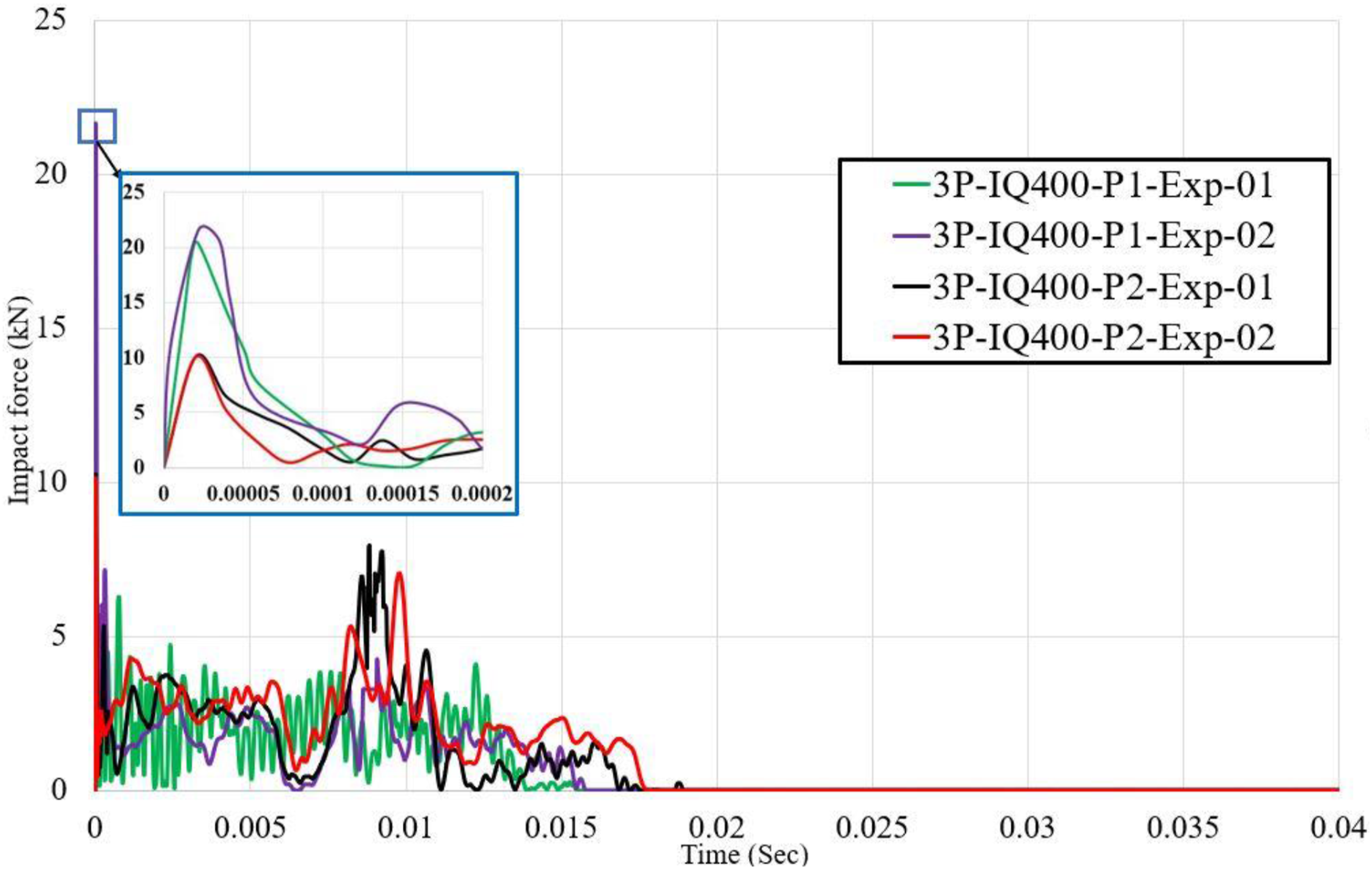
Influence of the velocity of impact on the initial peak force
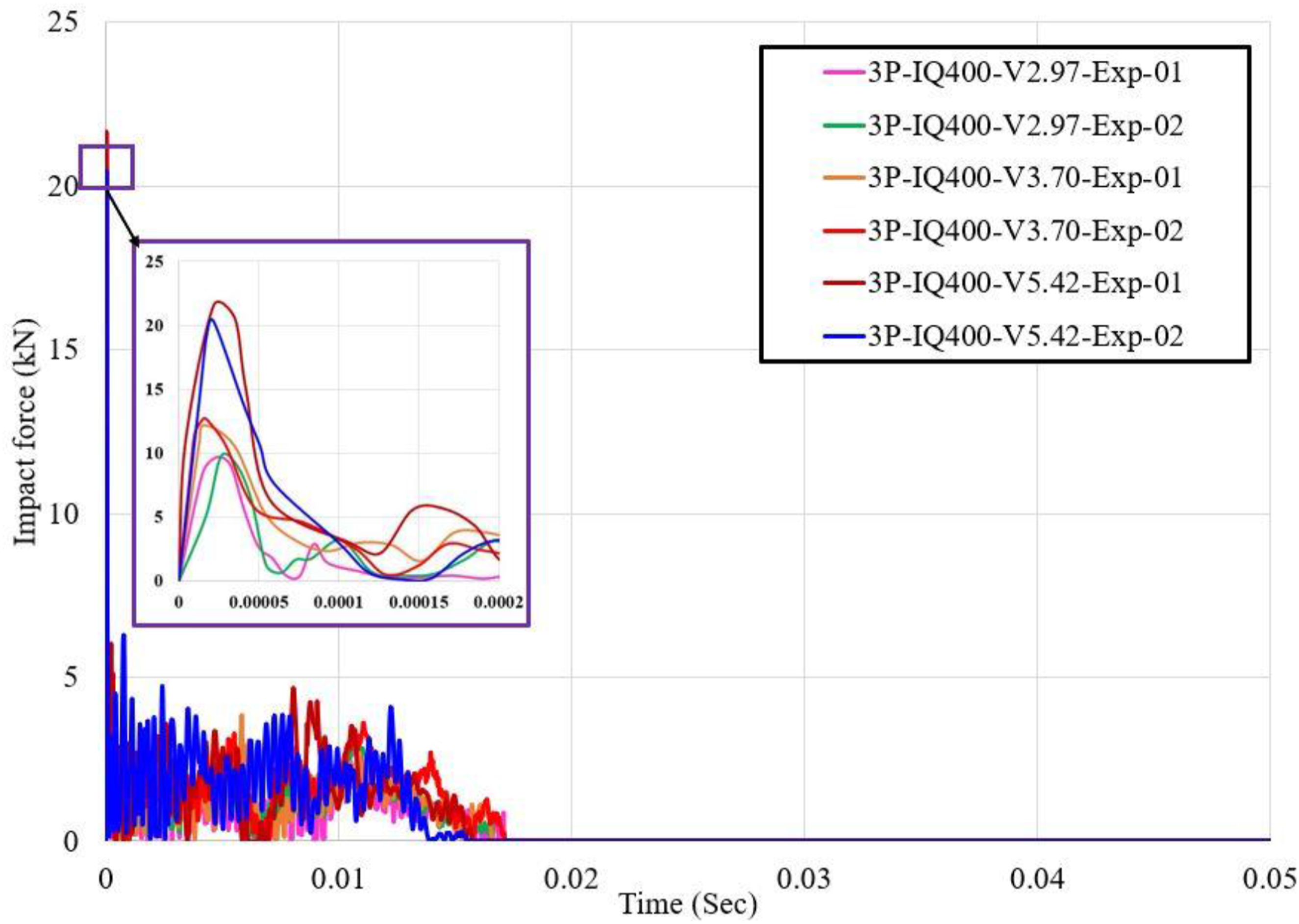
The study used three panels interlocked IQ400 to investigate the influence of the velocity of impact. The alteration in height of drop was used to achieve the change in velocity of impact. At a velocity of 2.97 m/sec, an impact force of 9.72 kN was recorded. This value increased to 12.44 kN and 20.92 kN at the impact velocity of 3.70 m/sec and 5.42 m/sec, respectively (refer to Figure 15). In this case, for an increase of 82% in velocity (from 2.97 to 5.42 m/sec), the impact force increased by 115%. This is also supported by Newton’s 2nd law of motion (refer to equation (3)). Force-time history for IQ 400 exposed to different velocities of impact.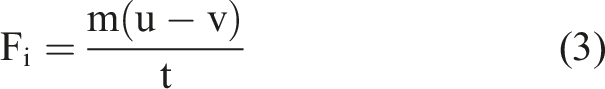
Plateau force
The plateau period in an impact event is an important phase in the event’s dynamics, involving the plate and impact head moving together and remaining in contact after the initial peak force. The force generated during this phase is known as plateau force. Similar to the initial peak force, the plateau force is also influenced by the structural and load-related parameters.
Influence of interlocking of panels on plateau force
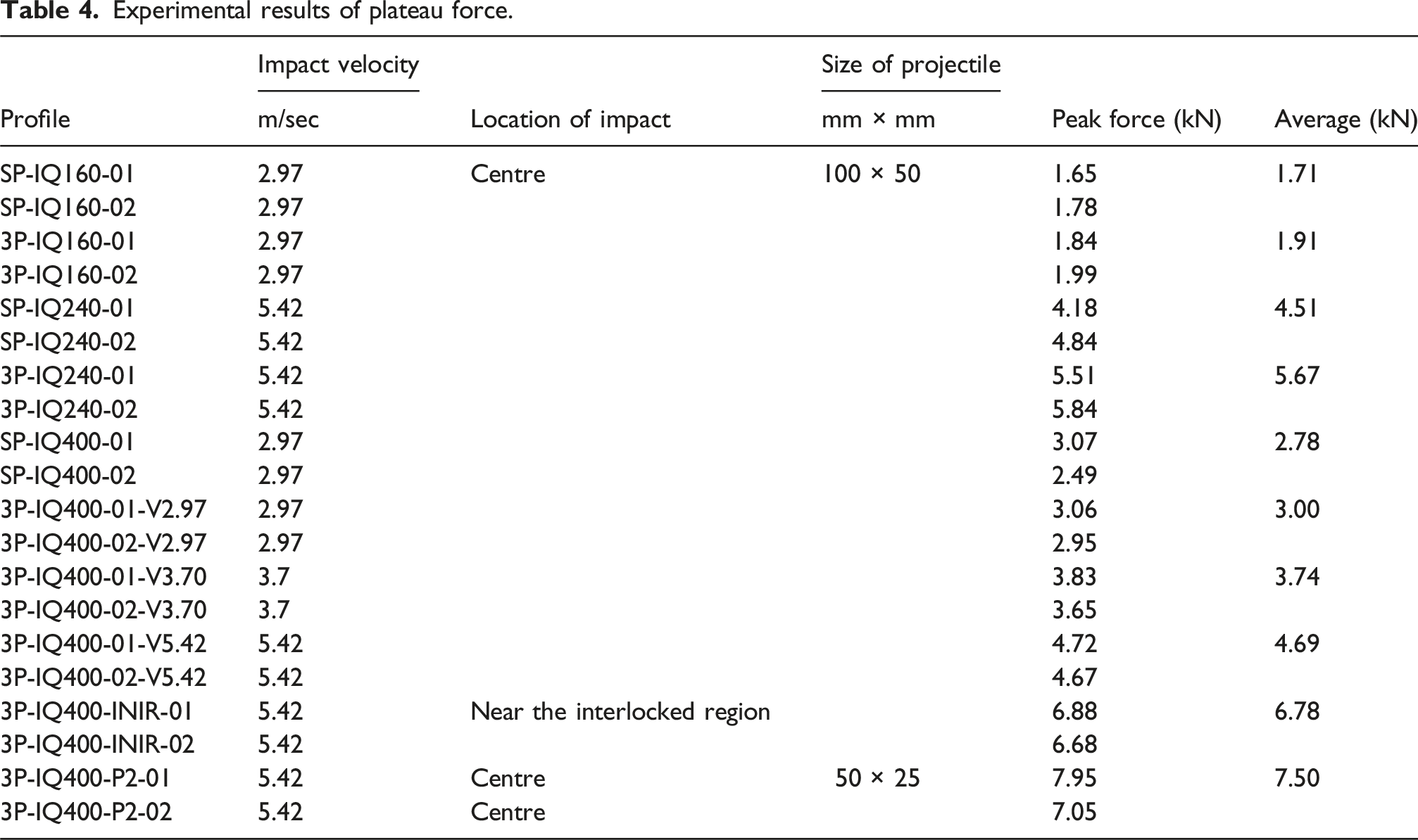
Experimental results of plateau force.
Influence of the location of impact on plateau force
The influence of the impact location on extruded panels’ plateau force was investigated considering two scenarios, (1) impact at the centre, and (2) impact near the interlocking region (refer to Figure 8). The plateau impact force was 4.69 kN when targeting the IQ 400 panels at the centre but increased to 6.78 kN near the interlocking area (refer to Table 4), indicating a 44% increase in the plateau force (refer to Figure 13). This increase is attributed to the panel’s higher global stiffness near the interlocking region, which results in a higher plateau force when the projectile strikes this area.
Influence of the area of contact at the impact on plateau force
Unlike the initial peak force, which reduced when the area of contact at impact was reduced, the plateau force increased. When the area of contact was reduced to a quarter by employing a 25 mm × 50 mm projectile in place of 100 mm × 50 mm, the plateau force was increased from 4.69 kN to 7.5 kN (see Figure 14). This is because, for the smaller impact area, the projectile’s force is concentrated over a smaller target surface, resulting in higher localized stresses. This led to a higher plateau force (refer to Table 4).
Influence of the velocity of impact on the plateau force
Similar to the initial peak force, the plateau force also increased with the increase in the impact velocity. As given in Table 4, the plateau force was 3.0 kN at 2.97 m/sec. This value increased to 3.74 kN and 4.69 kN at 3.70 m/sec and 5.42 m/sec, respectively (refer to Figure 15). This increase in plateau impact force is because of the increase in the impact energy caused by the velocity.
Maximum deflection
Figure 15 shows the deflection-time history of the single panel (IQ160) exposed to the velocity of 2.79 m/sec. The value of the displacement is zero at peak impact force as there is a lag in the response. In all of the experiments, the displacement progressively grows to its maximum value at plateau force (refer to Figure 16) and then reduces when the extruded aluminium panel rebounds. After the panel and impact head separate, the panel recovers the elastic component of the displacement and begins to vibrate freely until the energy is damped away. This vibration causes the displacement curve to oscillate somewhat. As the experimental study was based on the low velocity of impact, the values for the residual deflections were very small almost negligible for all the panels investigated (refer to Figure 16). Deflection-time history of the single panel (IQ160) exposed to the velocity of 2.79 m/sec.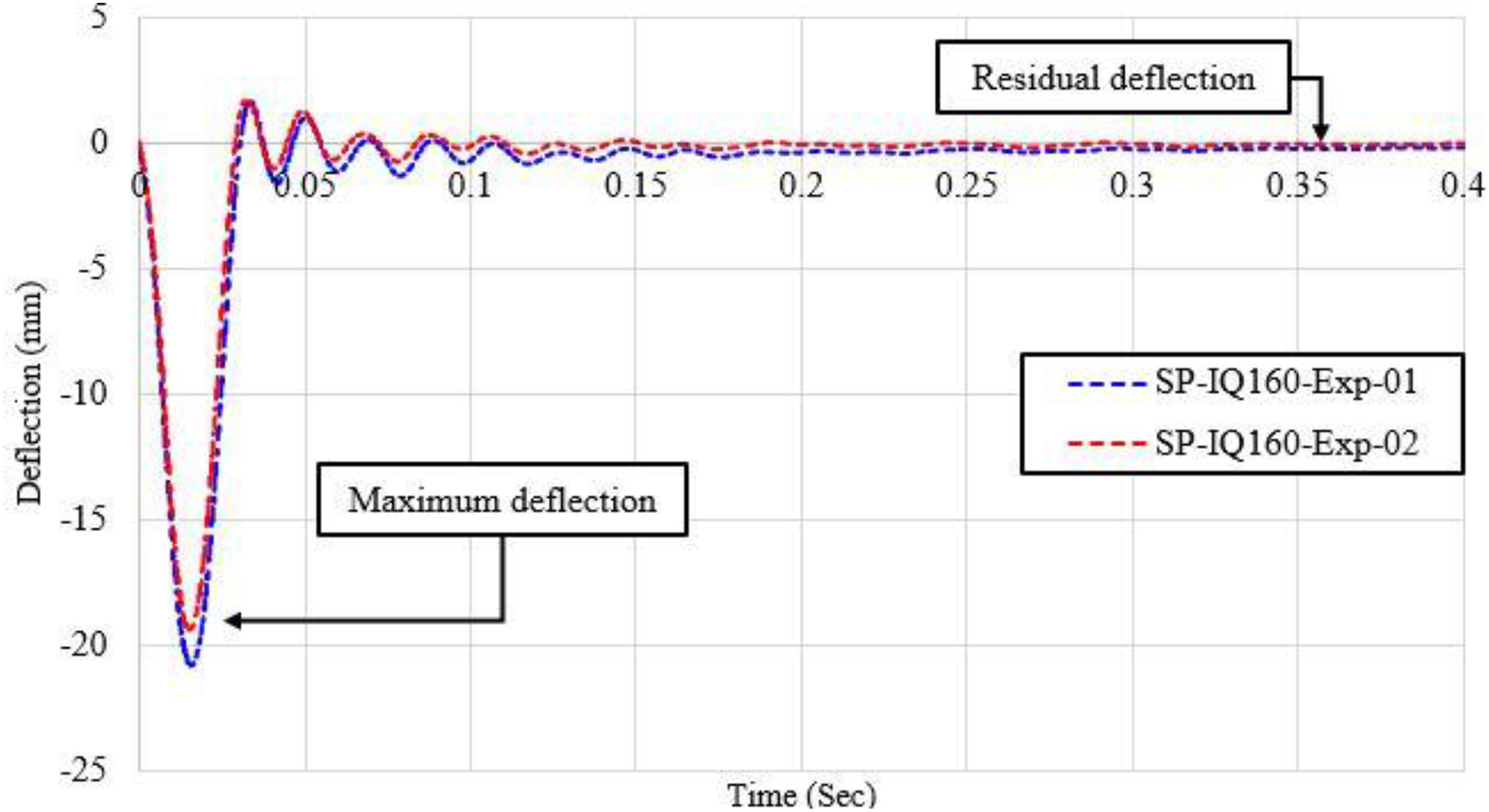
Influence of interlocking of panels on maximum deflection
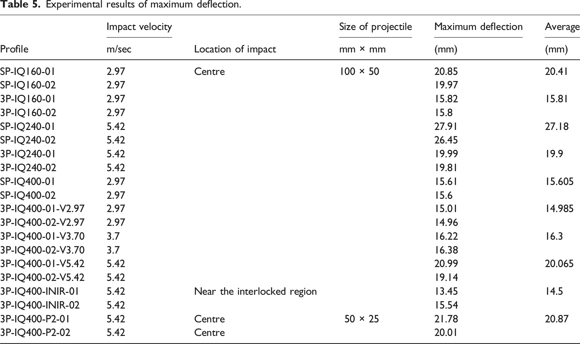
Experimental results of maximum deflection.
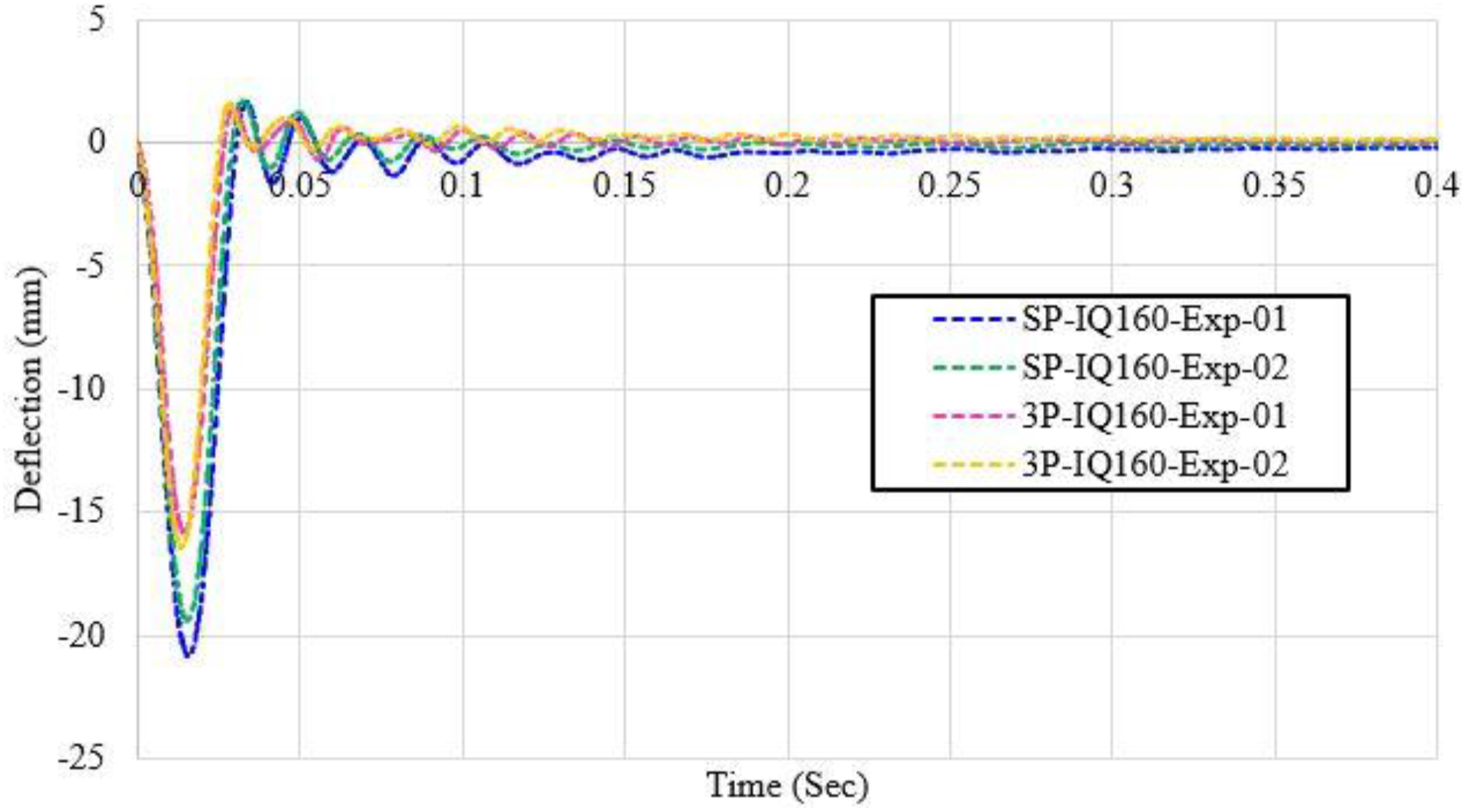
Deflection-time history for single and interlocked panels IQ 160 (V = 2.97 m/sec).
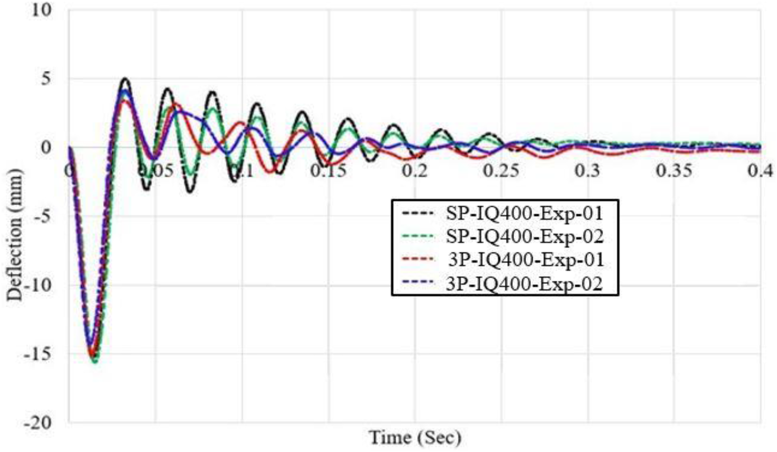
Deflection-time history for single and interlocked panels IQ 400 (V = 2.97 m/sec).
Influence of the area of contact at the impact on maximum deflection
The extruded aluminium cladding system exposed to the impact of a 100 mm × 50 mm projectile at a velocity of 5.42 m/sec resulted in a maximum deflection of 20.06 mm (refer to Table 5). The value of maximum deflection recorded by subjecting the system to a 25 mm × 50 mm projectile was 20.87 mm (see Figure 19). Thus for a quarter reduction in the area of contact at the impact, around a 4 % increase in maximum deflection was recorded. This increase in maximum deflection at a smaller area of contact is due to a higher concentrated load over a small area. Deflection-time history for IQ 400 exposed to projectiles with different areas of contact and the same mass (of 4 kg) at v = 5.42 m/sec.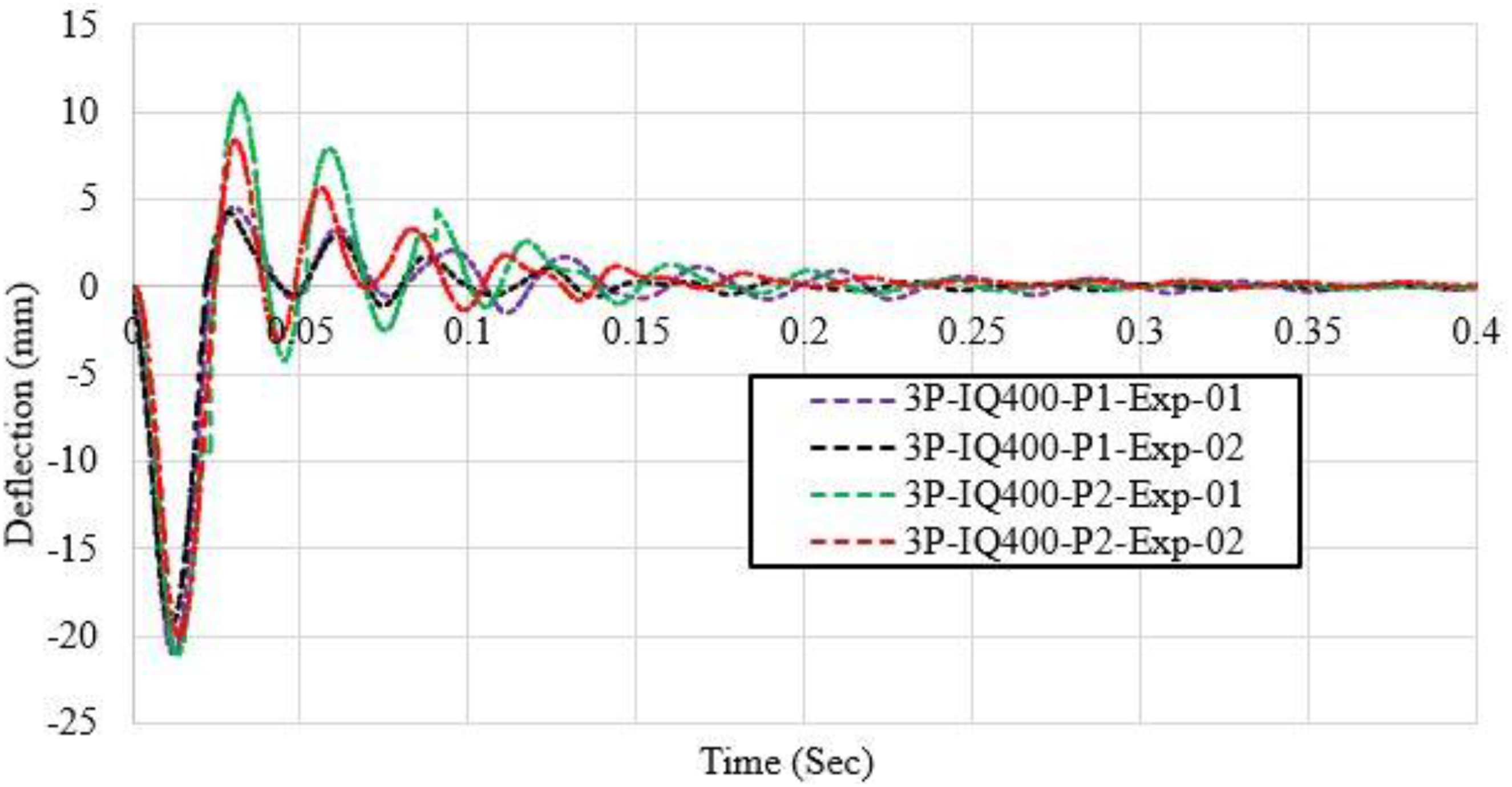
Influence of the location of impact on maximum deflection
The values for maximum deflection recorded by exposing the extruded aluminium cladding system to the impact of the projectile at different locations are given in Table 5. Interlocked panels of IQ 400 were impacted at the centre and close to the interlocked region. The velocity of impact was 5.42 m/sec. The value of maximum deflection recorded while the impact was at the centre was 20.06 mm. This maximum deflection was reduced by 27.7 % to the value of 14.5 mm when the impact was close to the interlocked region (see Figure 20). The relatively higher global stiffness near the interlocked region of the panels controlled the maximum deflection. Deflection-time history for interlocked panels IQ 400 at different locations (V = 5.42 m/sec).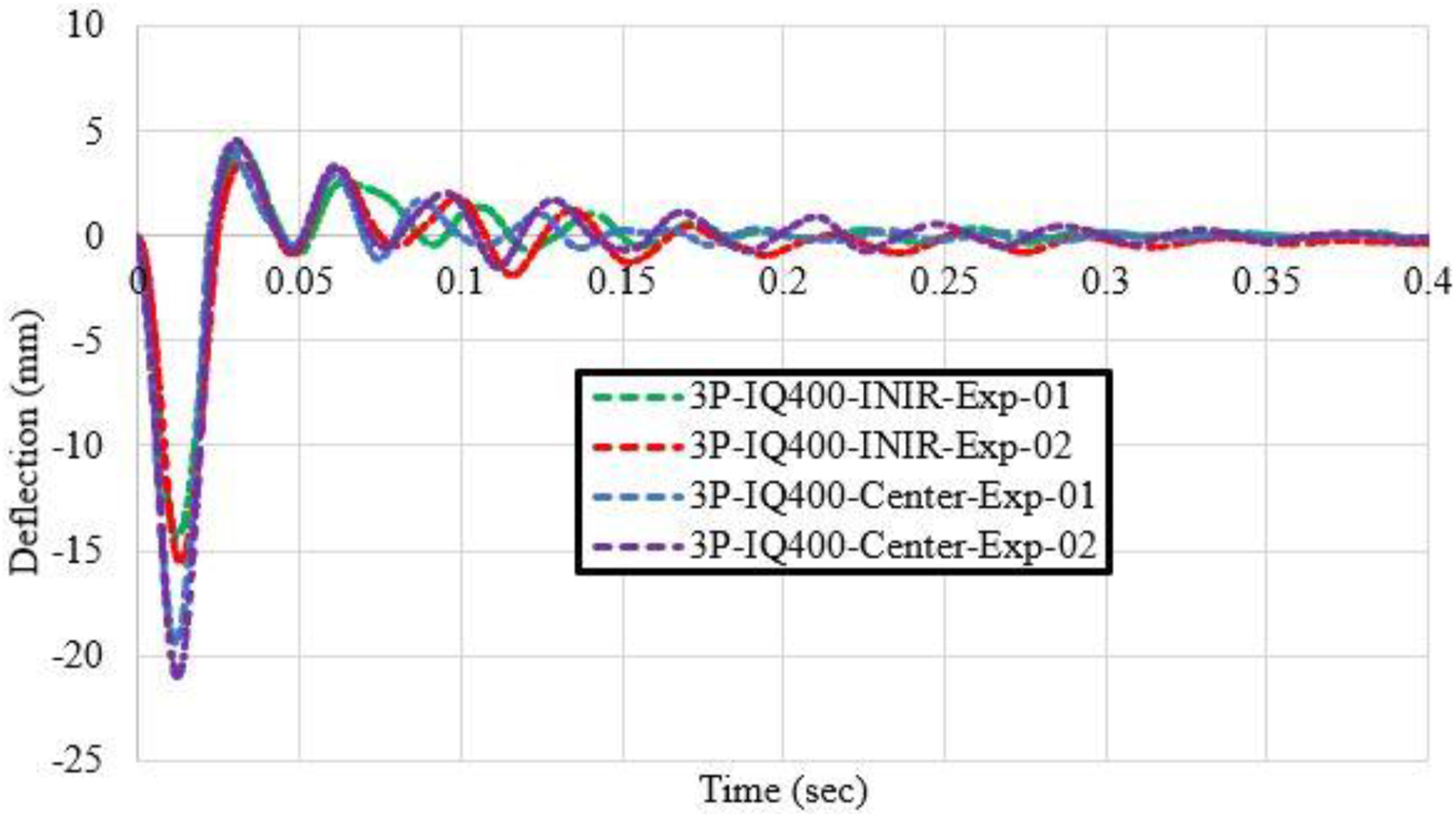
Influence of the velocity of impact on the maximum deflection
At a velocity of 2.97 m/sec targeted at the centre, the IQ 400 cladding system experienced a deflection of 14.98 mm (refer to Table 5). The maximum deflection at the centre of the cladding system increased to 16.3 mm and 20.06 mm at a velocity of 3.7 m/sec and 5.42 m/sec, respectively (refer to Figure 21). The increase in maximum deflection with increased velocity is due to the higher kinetic energy of the impacting edge. This energy is transferred to the target, causing higher deflection. The relationship between kinetic energy and velocity is quadratic (Johansson, 1990), meaning even a minor increase leads to a substantial boost in kinetic energy and thus the resulting maximum deflection. Deflection-time history for IQ 400 exposed to different velocities of impact.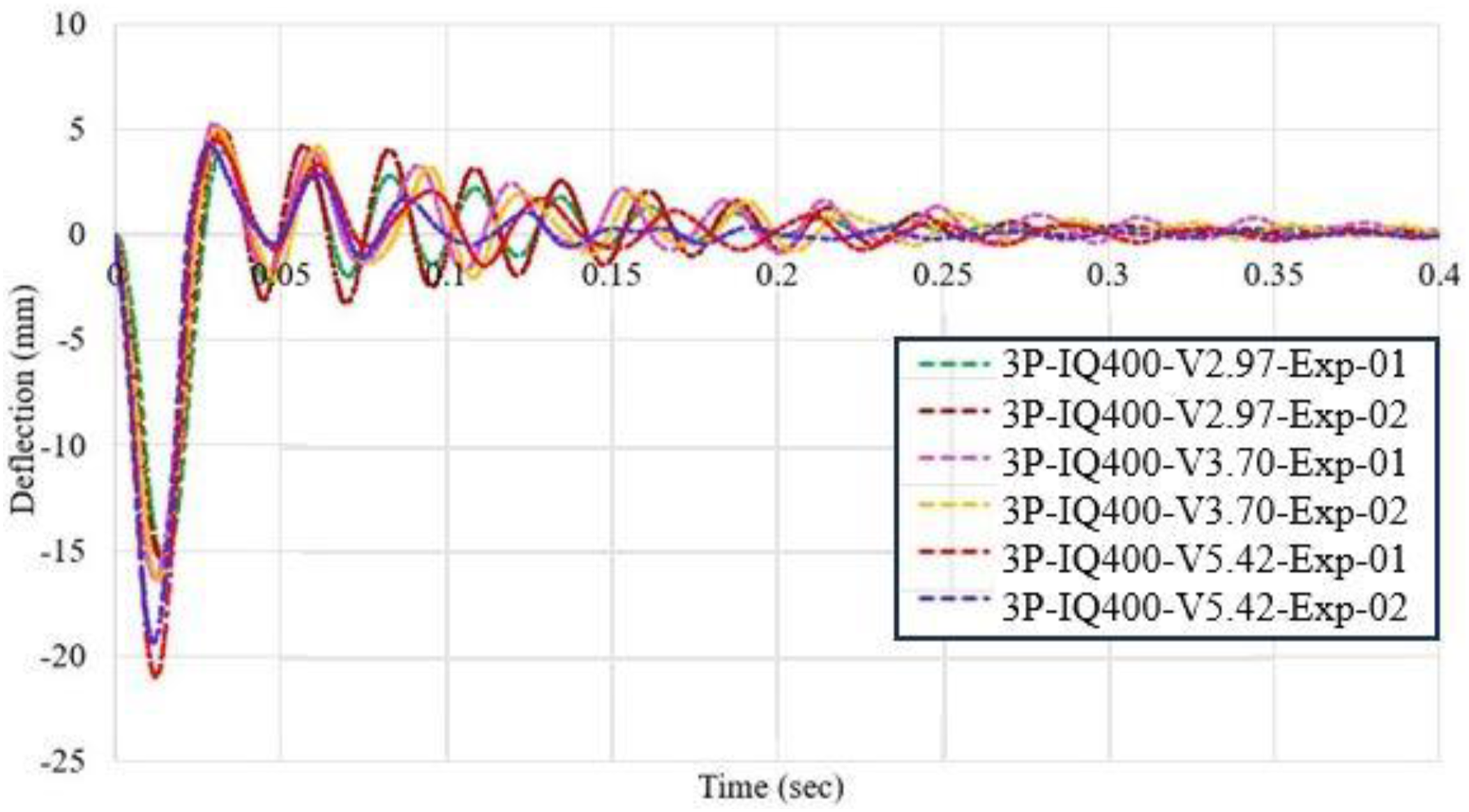
Failure modes
As all the panels experienced low-velocity impacts, the post-impact examination of the cladding panel system revealed no notable global or local failure modes, such as permanent deformations. The recorded values of residual deflections measured by the LVDTs were nearly zero (refer to Figures 16–19).
Numerical modelling
Dynamic explicit analysis was conducted using ABAQUS (6.14-5, 2012) software. The following sections offer an in-depth discussion on the development of a finite element model, covering the section elements, geometric configurations, material properties, boundary conditions, and analysis. This includes validation through comparisons of force-time and deflection-time histories.
Element type and size
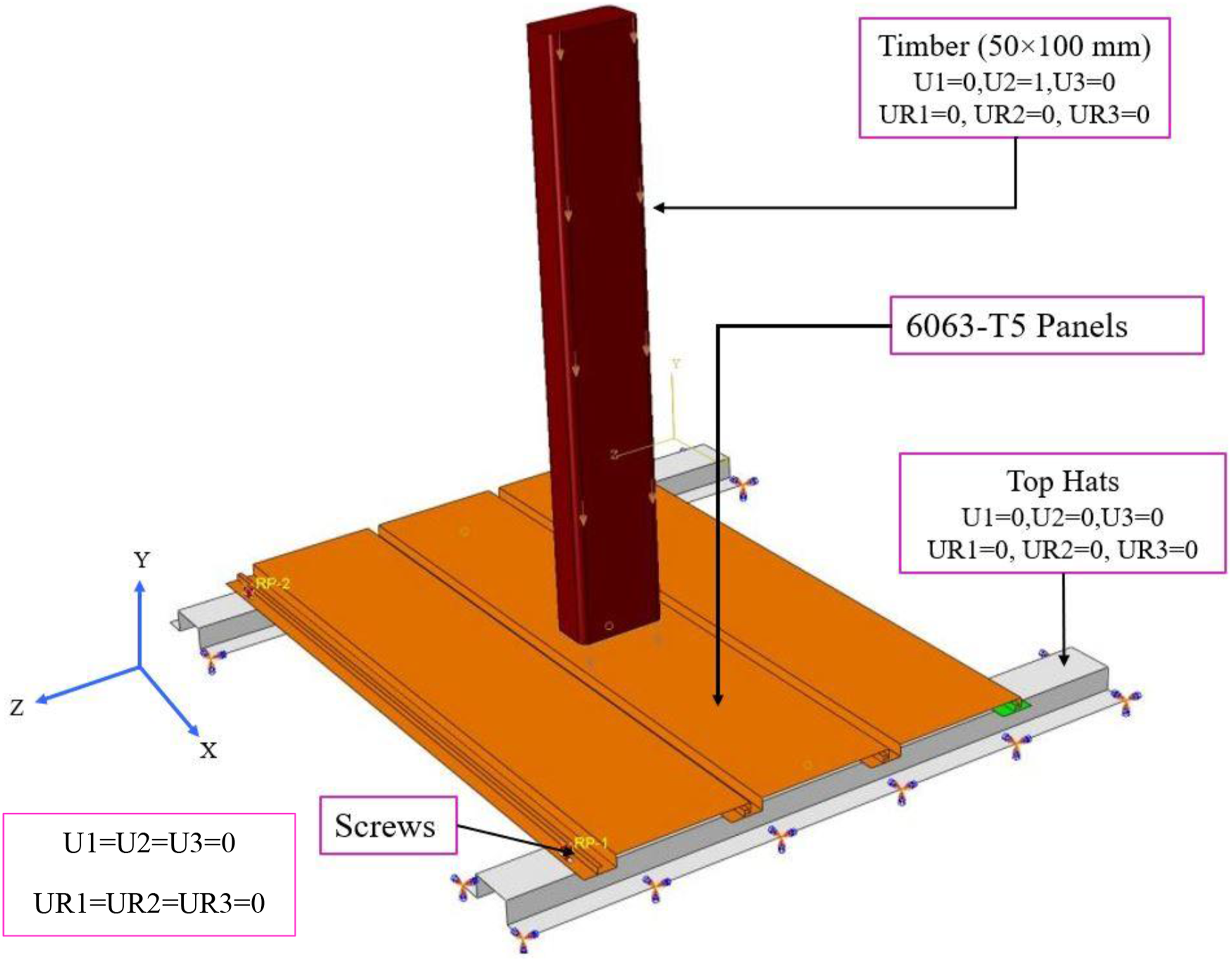
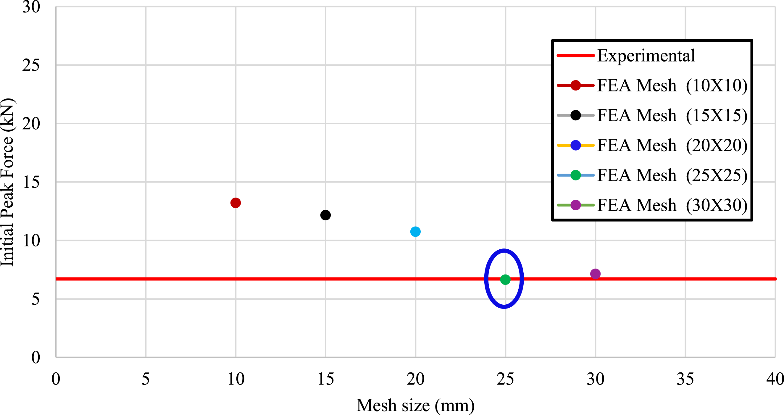
Choosing the right element type and size is crucial in numerical modelling to accurately simulate the behaviour of extruded aluminium cladding panels. In this study, the 6063-T5 aluminium panels, along with top hats and starter plates, were modelled using S4R shell elements. The projectile, on the other hand, was simulated using C3D8R solid elements (as shown in Figures 22 and 23). The screws (#12 Hex Head self-drilling) were treated as rigid bodies. To fine-tune the finite element modelling of the aluminium plates, a convergence study was performed. This study determined that a mesh size of 25 × 25 mm for both the projectile and the panels yielded the most effective results for the model (refer to Figure 24). Single panel IQ160 subjected to the impact of timber projectile (V = 5.42 m/sec). Interlocked panels IQ160 subjected to the impact of timber projectile (V = 5.42 m/sec). Mesh convergence study.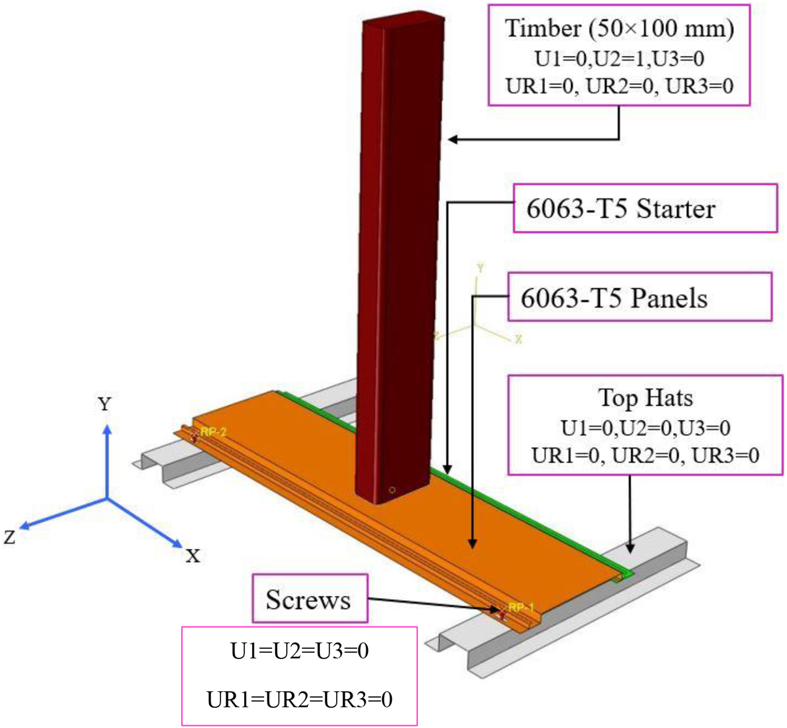
Geometric sections and material properties


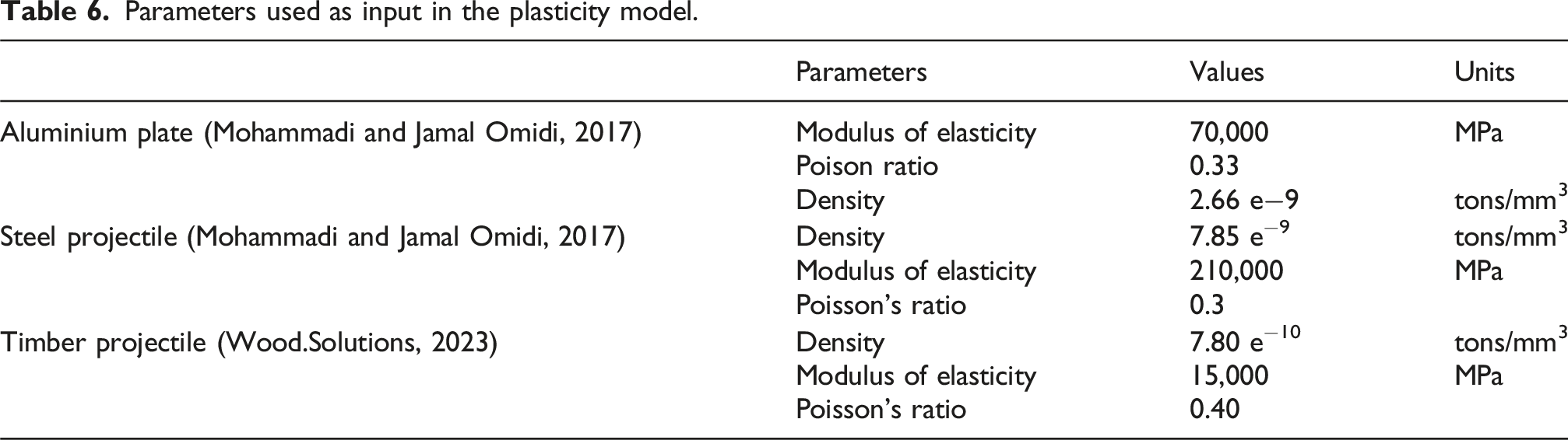
Parameters used as input in the plasticity model.
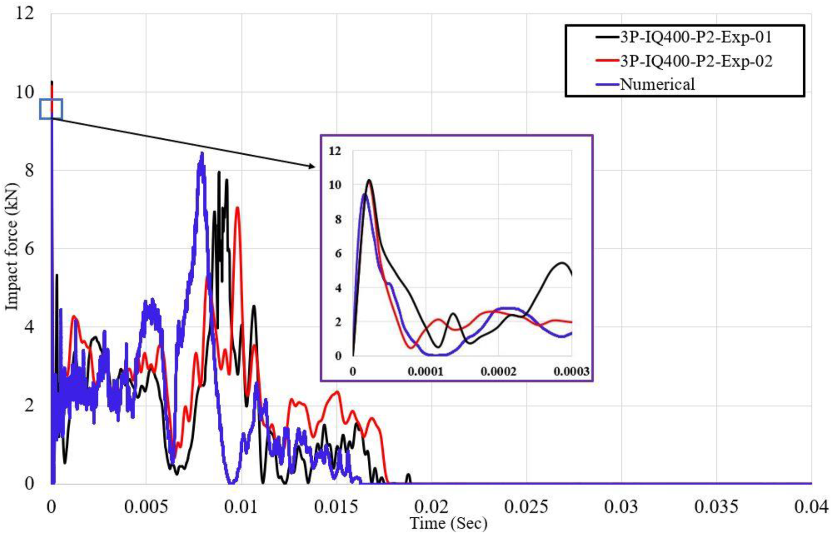
Loading and boundary conditions
To replicate the experimental setup for this study, applied load, boundary conditions, and constraints were defined in the model. The velocity was assigned as a predefined field to the projectile as shown in Figures 22 and 23. The movement of the extruded panels was restricted using screws and the starter panel. The boundary conditions applied to the projectile and top hats are as follows: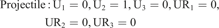
Contact algorithm
The surface-to-surface interaction with penalty contact was applied to the projectile and the extruded aluminium panel. The top of the projectile was assigned as the master and the top of the panel as the slave surface. General body contact was used for all the remaining surfaces. A friction coefficient between steel and aluminium was set at 0.61 in (Box, 2022; 2024; Javadi and Tajdari, 2006), whereas it was 0.3 in (Wang et al., 2018). Both these values were initially considered in this study. However, the results were not notably affected. Considering that the majority of researchers tend to use 0.61, it was decided to adopt this value in this study. A friction coefficient between aluminium and aluminium was set at 1.05 (Box, 2022; 2024; Javadi and Tajdari, 2006).
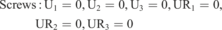
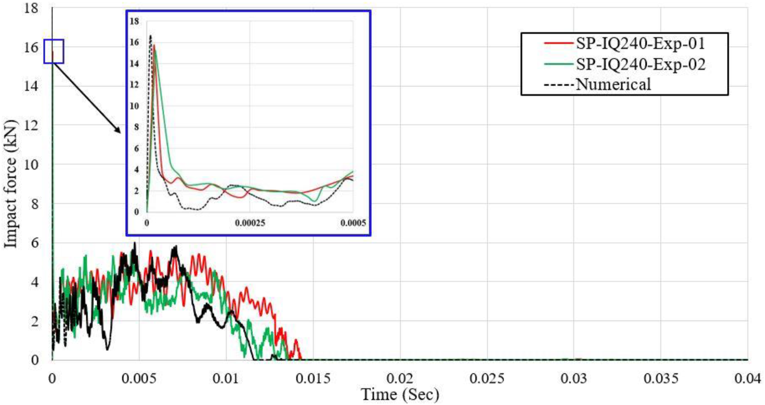
Validation of the finite element models
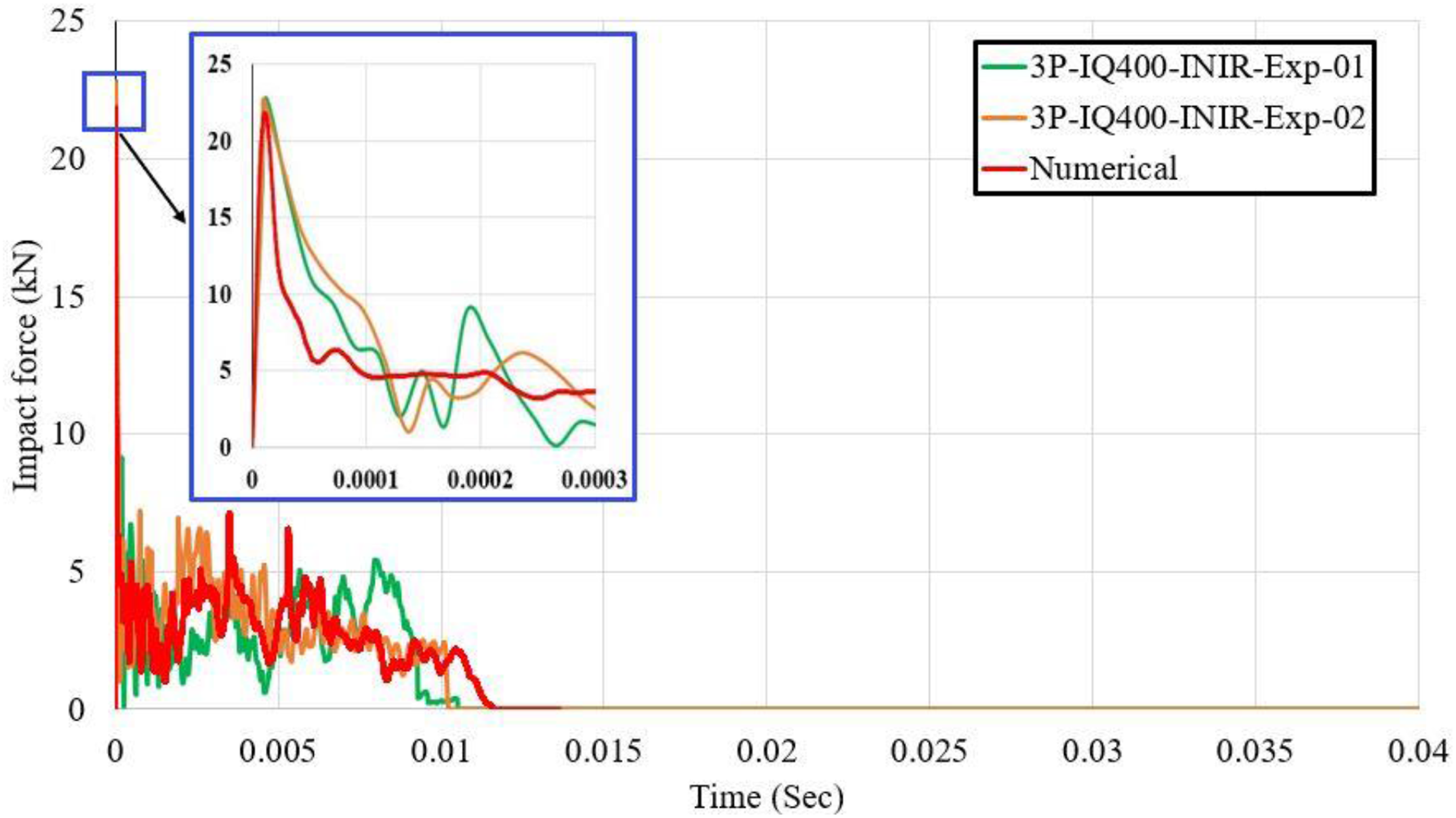
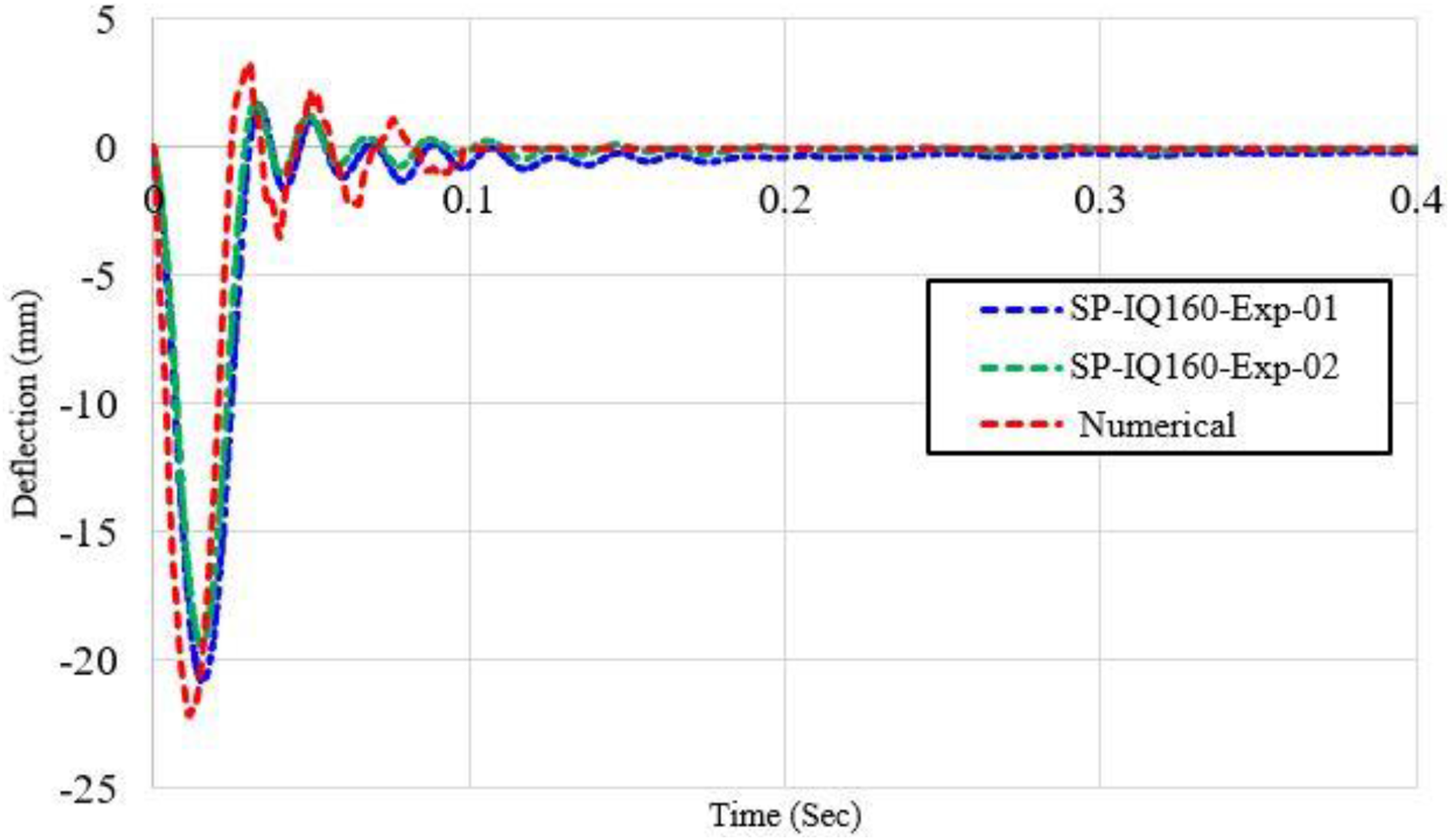
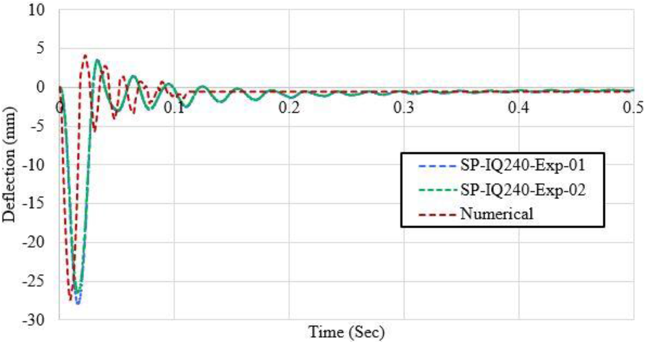
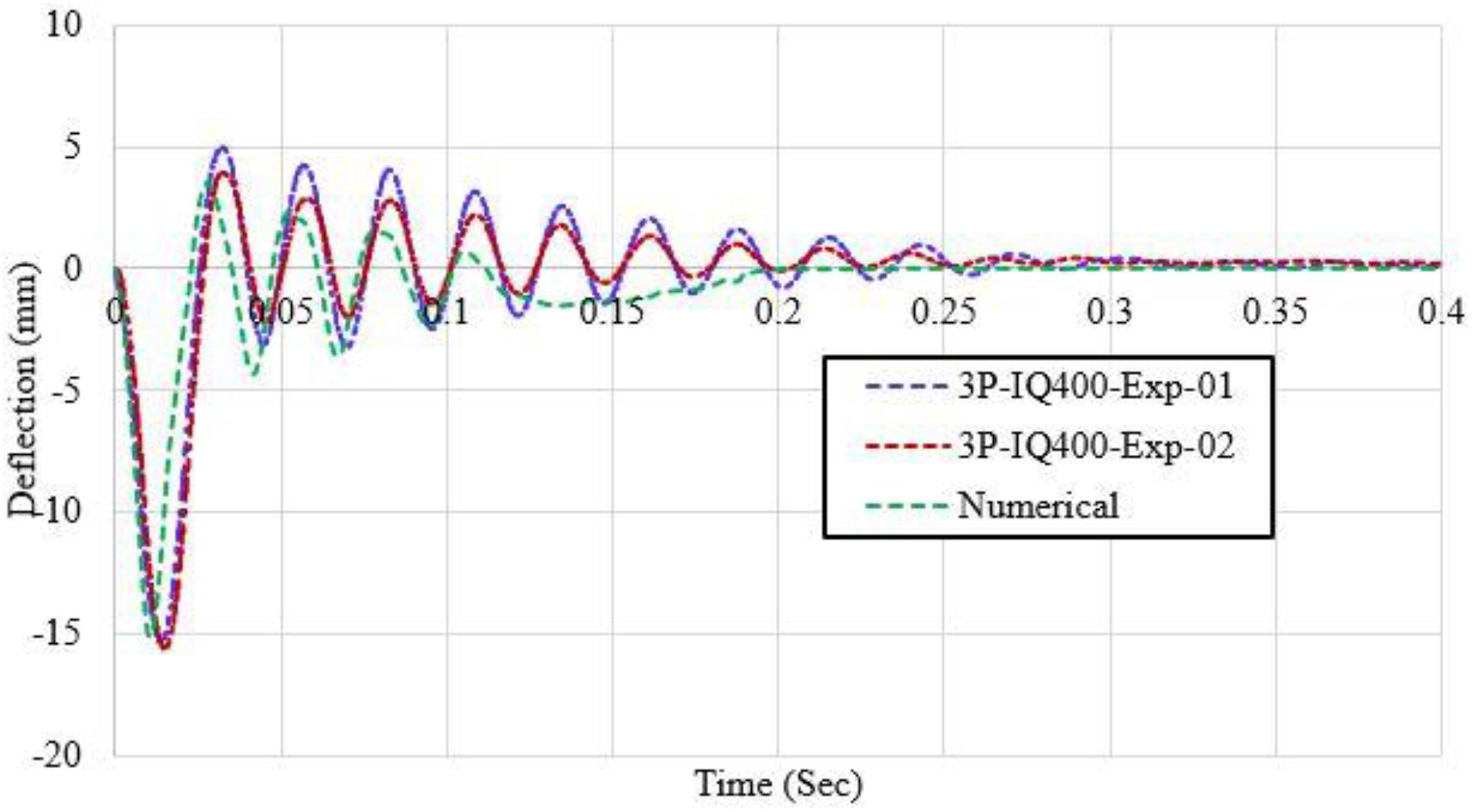
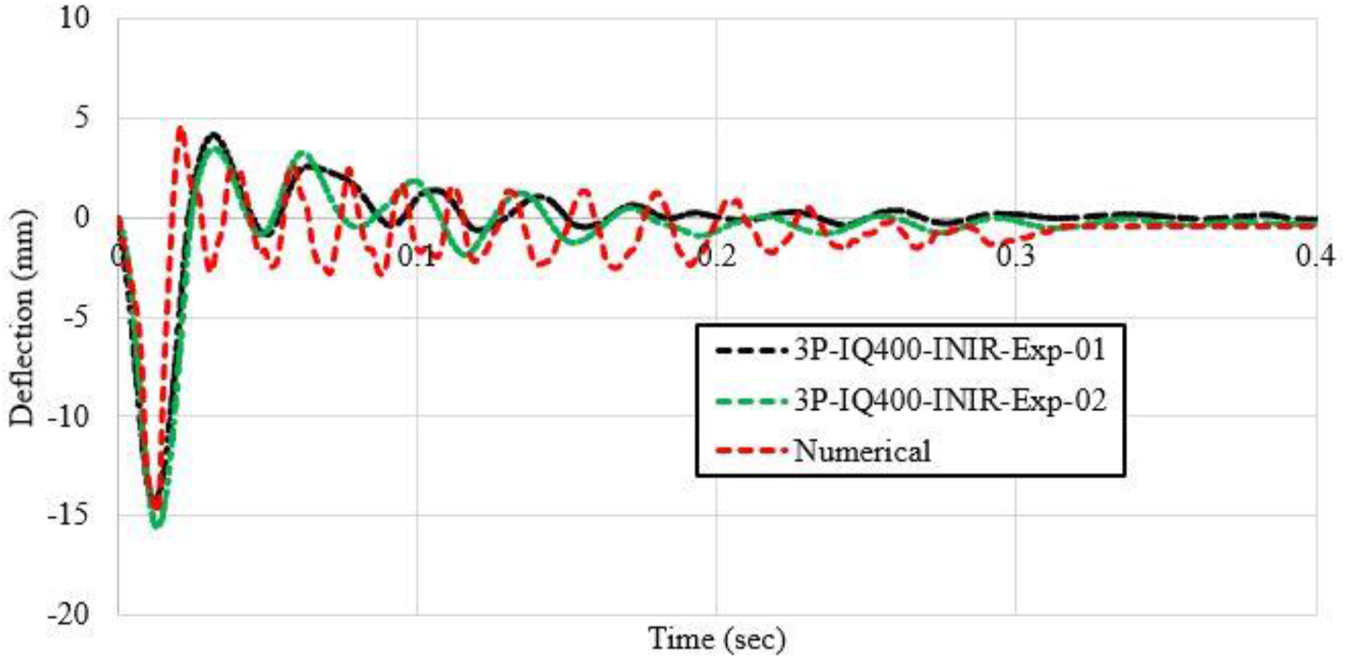
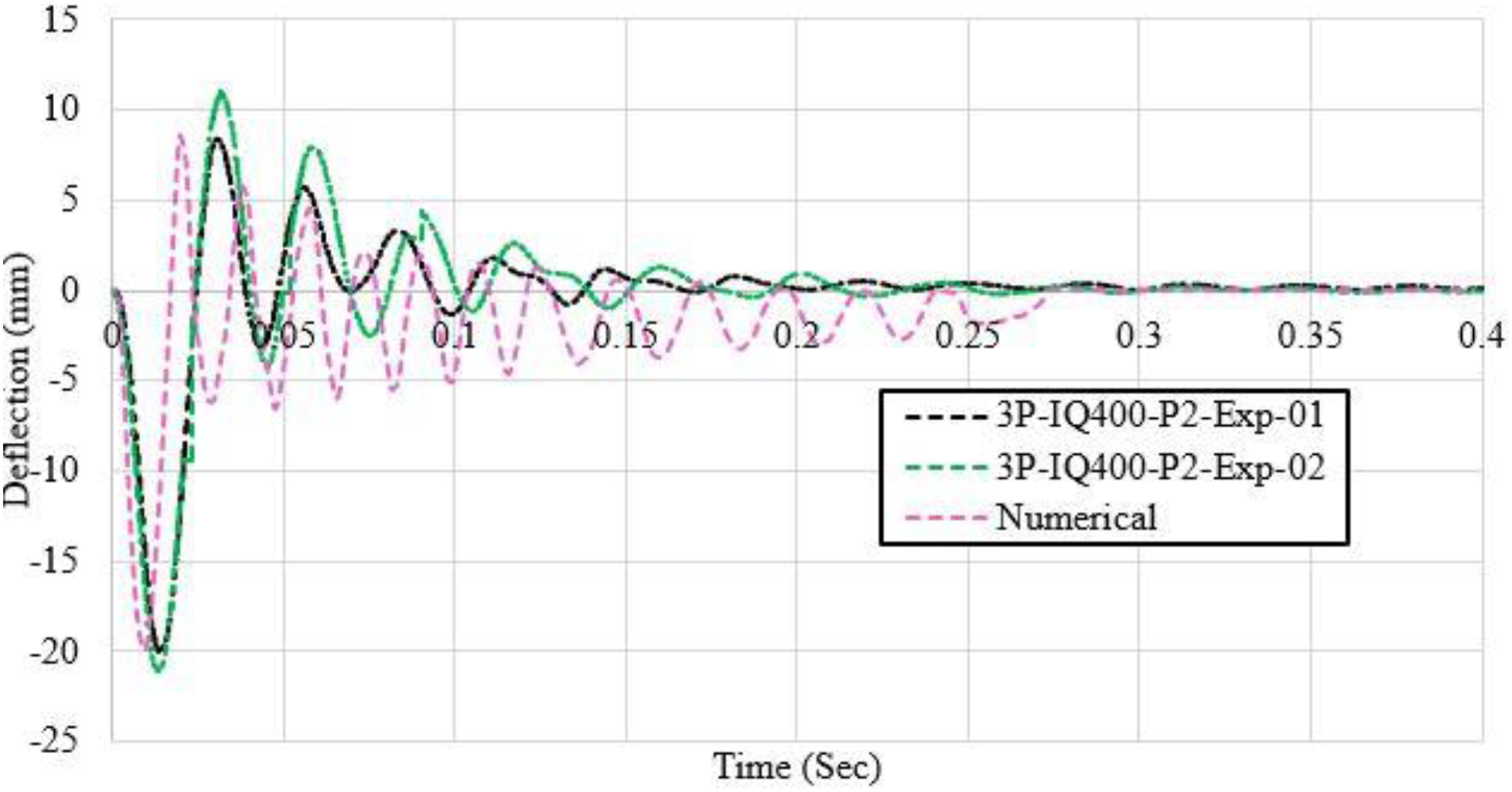
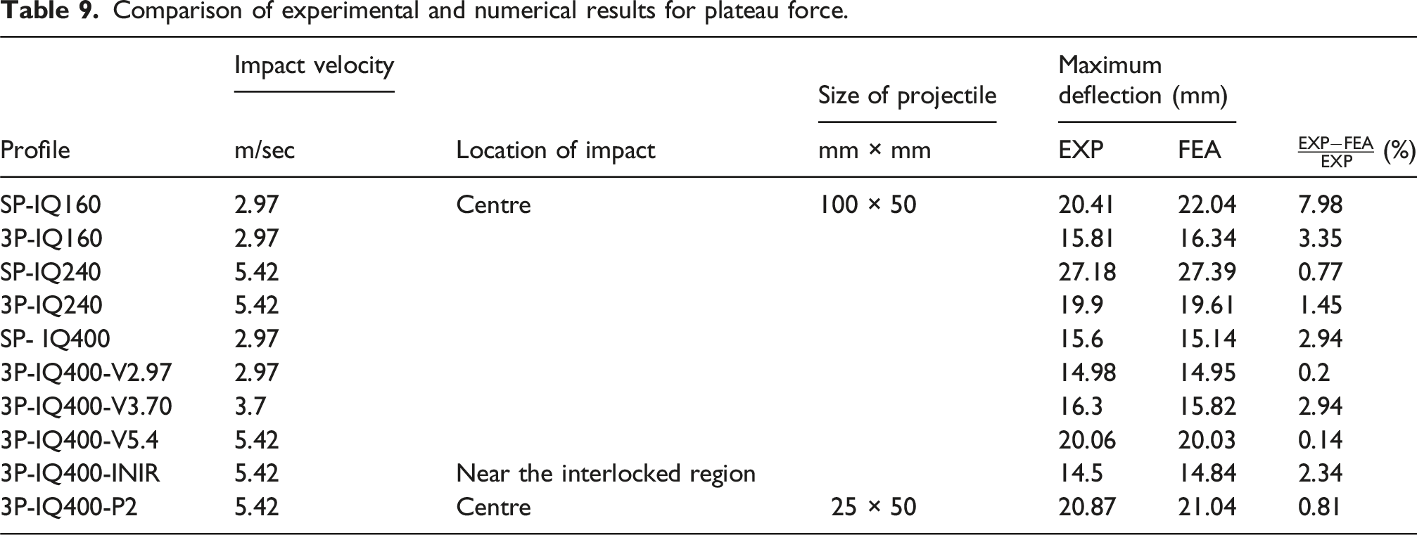
To validate the numerical model, the results of the FE simulations were compared with experimental data, focusing on force-time histories, deflection-time histories, initial peak force, plateau force, maximum deflection, and failure modes. A strong correlation was observed when comparing the force-time histories (see Figures 25–28) and deflection-time histories (Figures 29–33) for all profiles subjected to the impact of timber projectiles. Force-time history of a single panel system IQ160 exposed to velocity of 2.97 m/sec. Force-time history of an interlocked panel system exposed to the velocity of 5.42 m/sec. Force-time history of IQ400 panels exposed to P2 (a 25 mm × 50 mm projectile) at 5.42 m/sec. Force-time history of IQ400 impacted near the interlocked region at a velocity of 5.42 m/sec. Deflection-time history of a single panel system IQ160 exposed to velocity of 2.97 m/sec. Deflection-time history of single panel IQ240 exposed to velocity of 5.42 m/sec. Deflection-time history of interlocked panels system IQ400 exposed to velocity of 5.42 m/sec. Deflection-time history interlocked panels impacted at 5.42 m/s near an interlocked region. Deflection-time history of IQ400 interlocked panels with a 25 × 50 mm projectile at 5.42 m/s.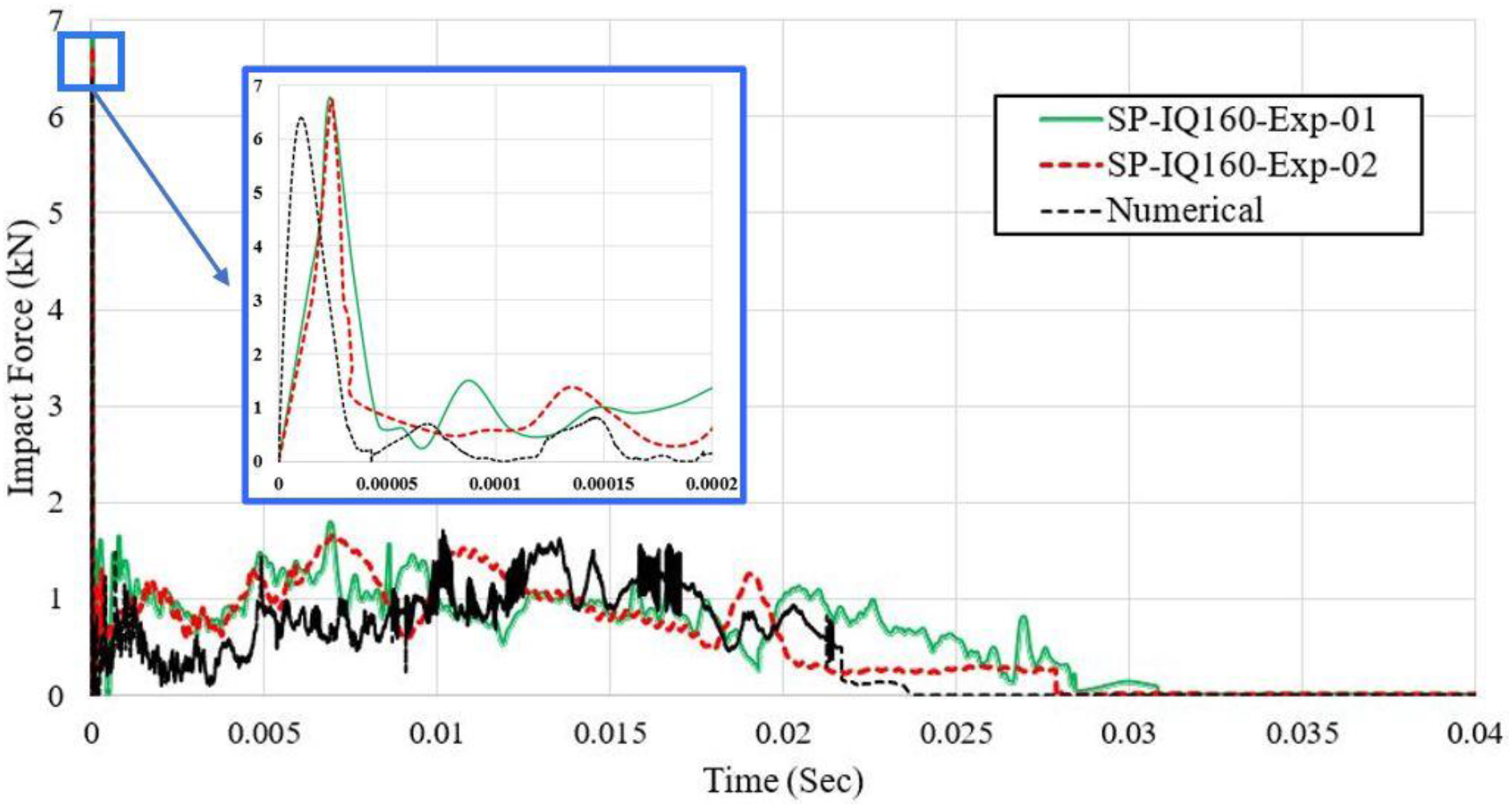
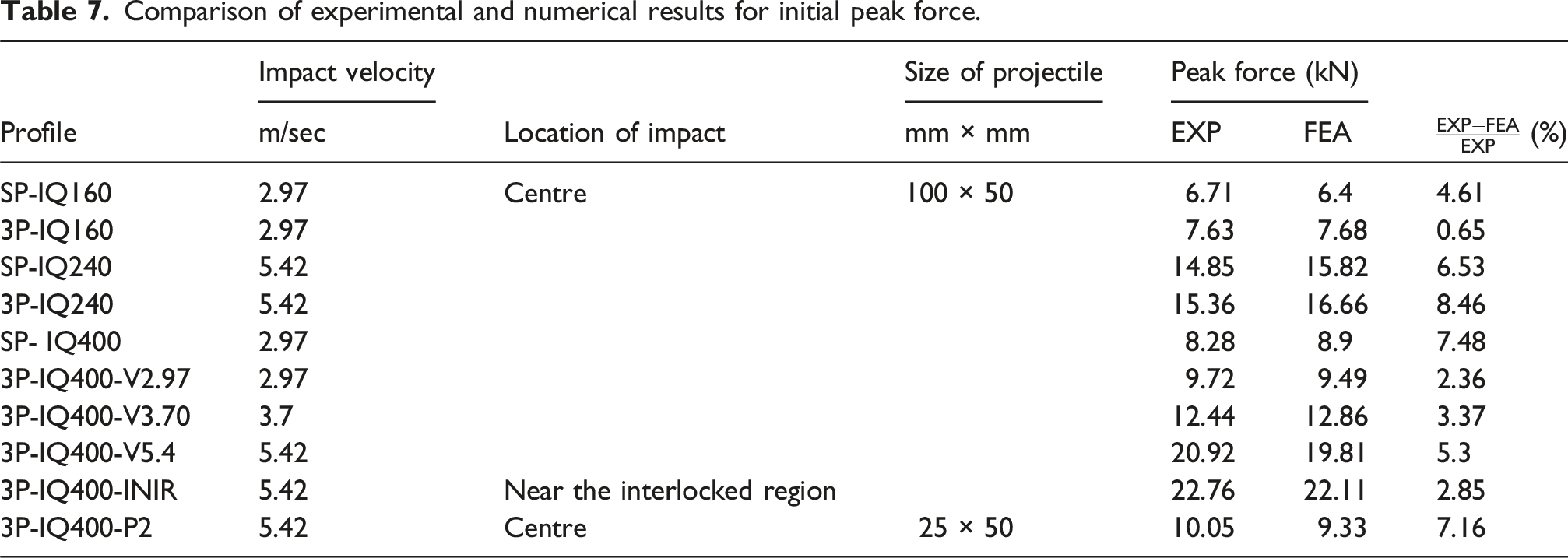
Comparison of experimental and numerical results for initial peak force.
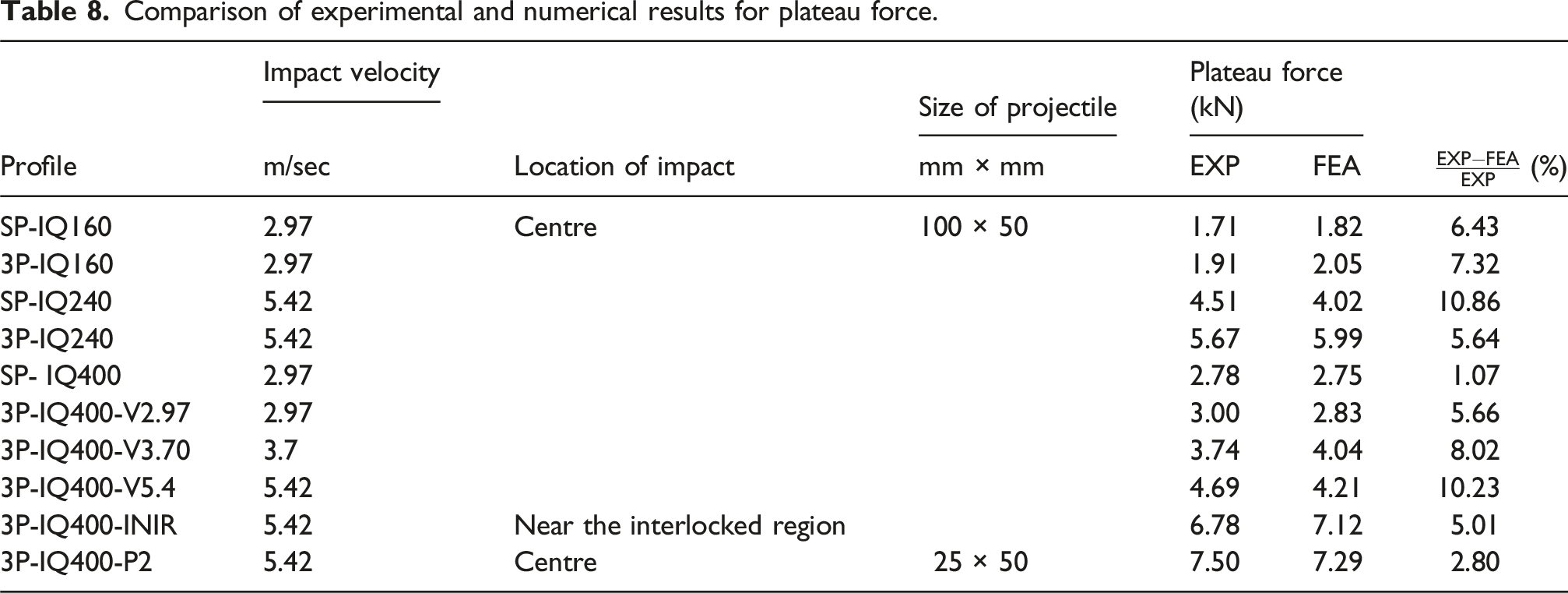
Comparison of experimental and numerical results for plateau force.
Comparison of experimental and numerical results for plateau force.
Upon examining fractures and buckling in the FEA model (refer to Figure 34), maximum stresses were observed near the panel’s corner (Figure 34(b)), attributed to the increased moment of inertia in that region, resulting in higher impact forces and stresses. Similar to the experimental observations, no permanent deformations were visually detected, confirmed by the minimal residual deflections (close to zero) predicted by the numerical model (Figures 29–33). Post-impact analysis of interlocked panels IQ160 exposed to 5.42 m/sec, (a) full view, (b) cross-sectional view at the location of impact.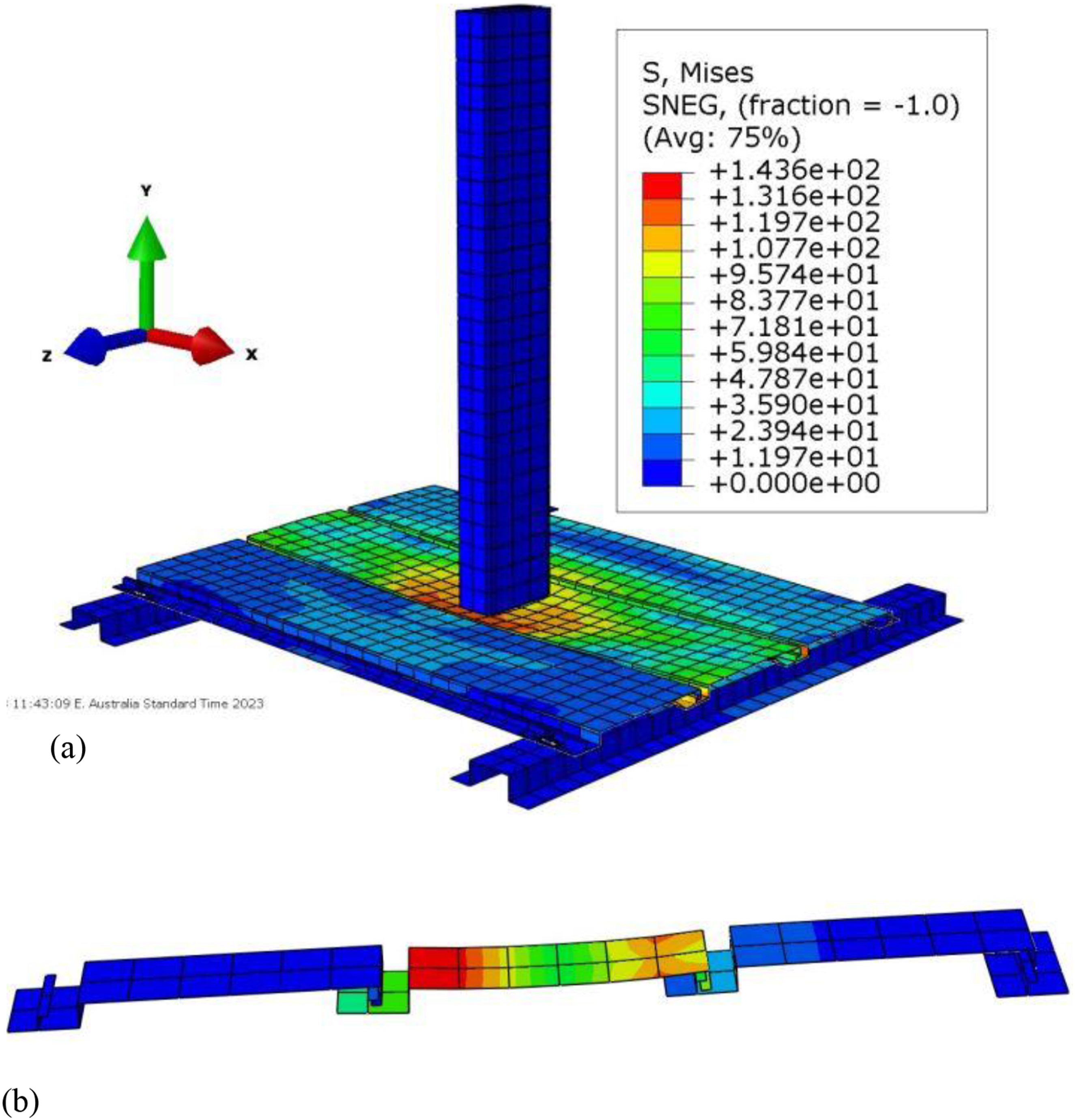
In conclusion, the strong agreement between the force-time histories, deflection-time histories, initial peak force, plateau force, and maximum deflection confirmed the accuracy and reliability of the proposed numerical model.
Parametric study
A parametric sensitivity study was conducted using a validated model to determine the influence of various structures and load-related parameters on the performance of the extruded aluminium cladding panel system exposed to impact loading which would then assist in developing equations. The performance was evaluated in terms of initial peak force, plateau force and maximum deflection.
Influence of the key parameters on the response of the panels
The influence of various structural and load-related parameters such as the thickness of the panels, the width of the panels, the type of alloy, velocity of impact, angle of impact (Figure 35) and location of impact on the peak force, plateau force and maximum deflection is evaluated in this section. The angle of impact.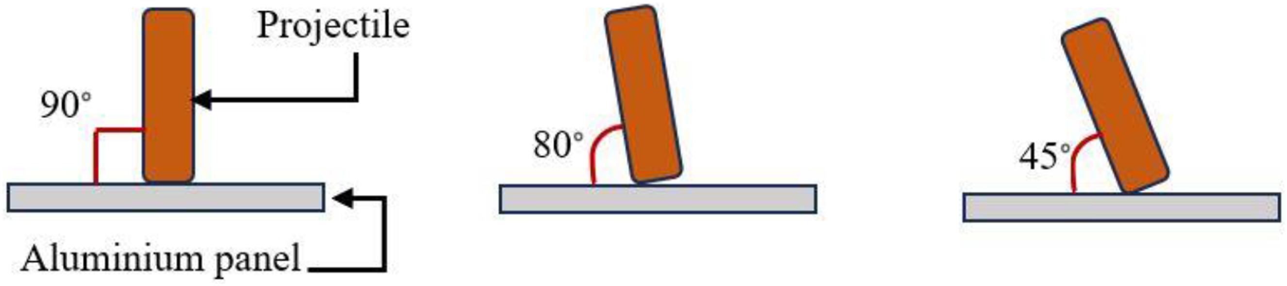
Initial peak force and plateau force
From the sensitivity analysis, several key parameters were identified that influenced the initial peak force and the plateau force (see Figures 36, and 37). Among the structural parameters, plate thickness exerted a substantial influence, with an increase leading to a corresponding rise in the initial peak force and plateau force. For a 16% increase in the thickness of the panel, an increase of 46% and 14.27% was recorded for the initial peak force and the plateau force, respectively. This behaviour is explained by the inherent relationship between plate stiffness and impact force, as thicker plates exhibit greater stiffness, resulting in higher forces during impact. Similarly, a 100% increase in the velocity of impact corresponded to an increase of 164% in the initial peak force and an 87% increase in the plateau force. This alignment with Newton’s second law underscores that higher velocities lead to more substantial impact forces. Peak impact force variation with respect to key parameters. Plateau force variation with respect to key parameters.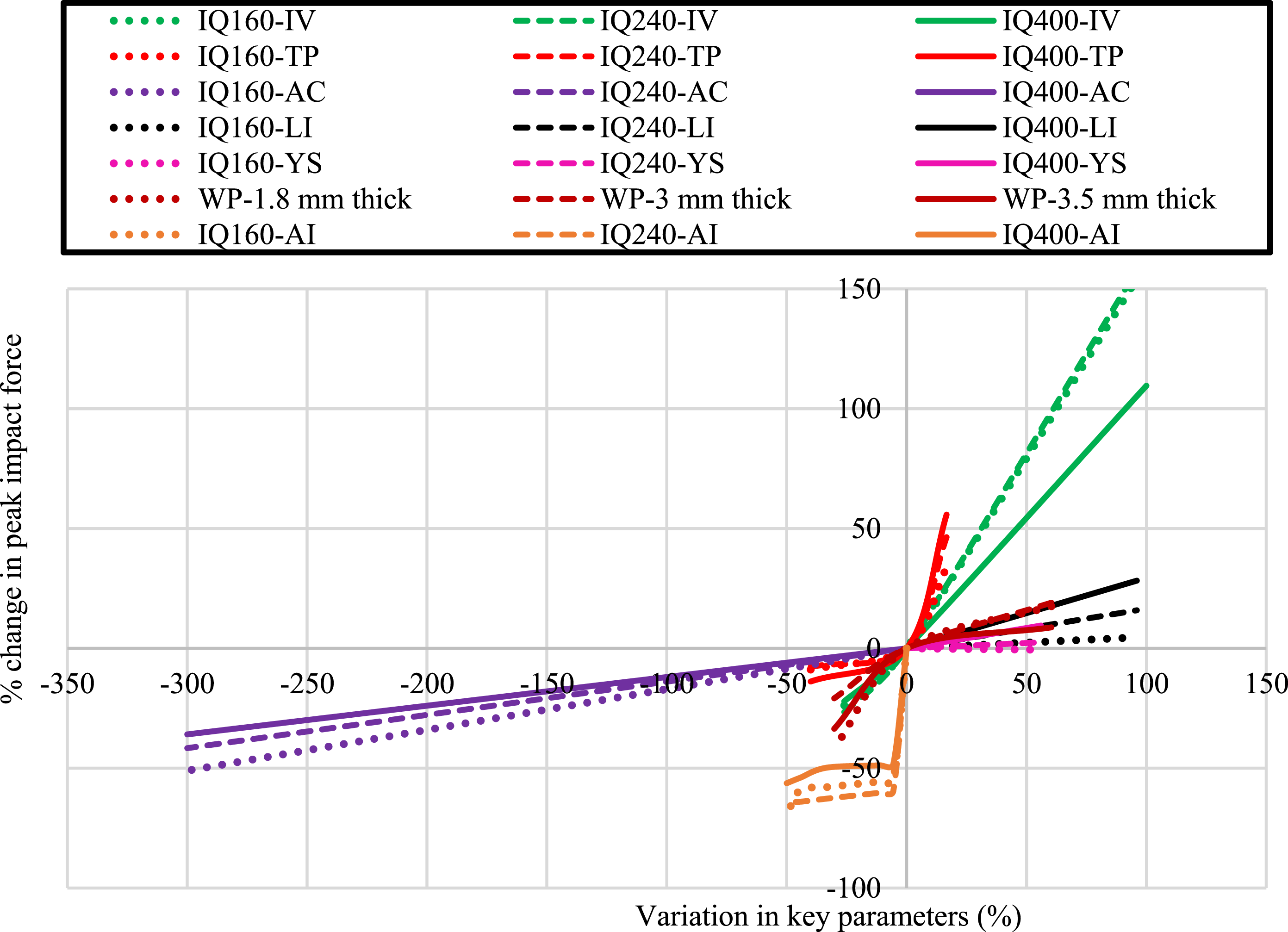
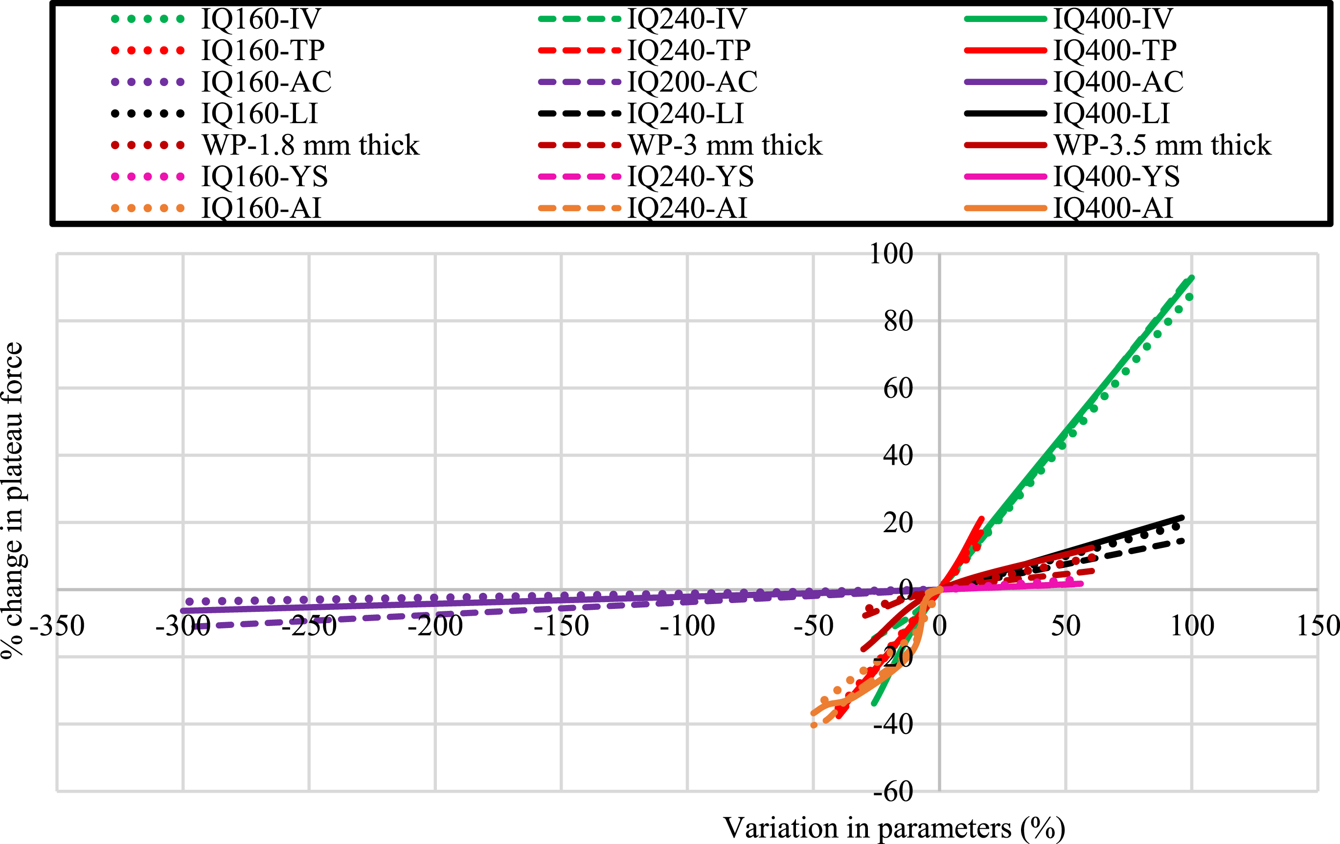
The angle of impact emerged as a crucial factor, demonstrating a significant 63% decrease in peak impact force and a 40% reduction in plateau force as the angle decreased from 90° to 45°. This reduction is attributed to the resolution of impact force into horizontal and vertical components at an angle, resulting in decreased force on the target panel.
The width of the panel exhibited an inverse relationship with impact force, indicating a 60% increase in width resulting in a 19% reduction in the initial peak force and a 9.67% decrease in the plateau force. This outcome is due to reduced contact stiffness with increased width, causing a reduction in the initial peak force and the plateau force.
The impact location played a significant role, with impacts closer to support (within 5%) leading to a 20% increase in both the initial peak force and the plateau force. This phenomenon is linked to increased stiffness and contact stiffness near supports, influencing the overall force exerted on the cladding.
Moreover, the area of contact at impact influenced the initial peak force and plateau force, with a reduction in the contact area by 300% leading to a 41% decrease in the initial peak force but an 11% increase in the plateau force. This behaviour arises from the fact that a larger contact area ensures a more even dispersion of force during impact, thereby contributing to a more robust initial impact. Conversely, when the impact area is smaller, the force exerted by the projectile becomes concentrated on a limited surface. This concentration can lead to local deformation and material failure, ultimately resulting in a reduction of the overall impact force.
In summary, the parameters that affected the peak impact force and the plateau force are ranked based on their maximum influence as follows: Plate thickness had the most significant influence, followed by the velocity of impact, angle of impact, location of impact and contact area. However, the width of the panel and the type of alloy exerted minimal influence on the impact forces.
Maximum deflection
A sensitivity analysis was conducted to find out the influence of the key structural and load-related parameters on the deflection of panels (see Figure 38). Among these parameters, plate width emerged as a significant parameter, with an increase (60%) leading to an increase of 21% in maximum deflection. Maximum deflection variation with respect to key parameters.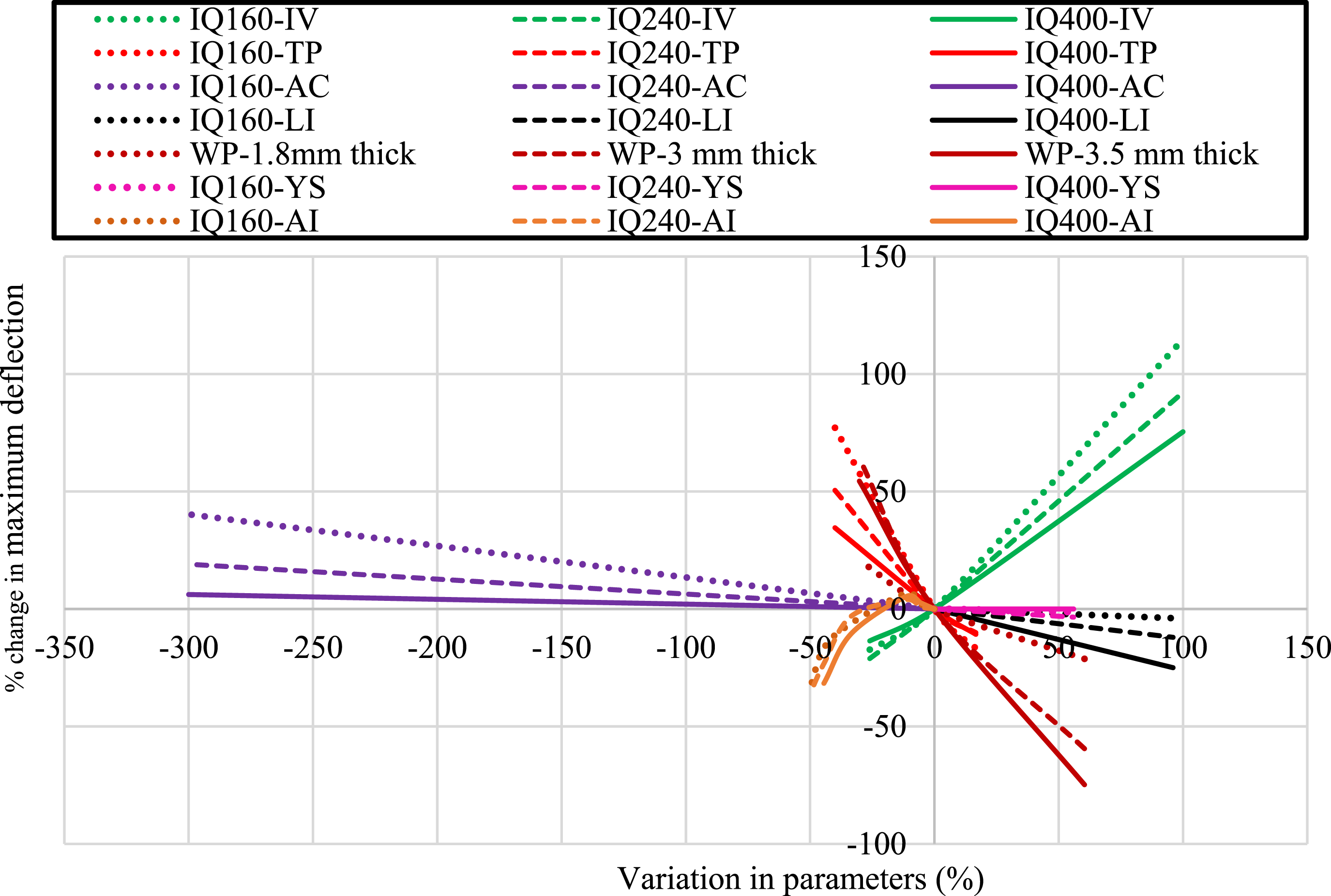
Similarly, a 100% increase in impact velocity corresponded to a 92% increase in maximum deflection. This alignment with Newton’s second law emphasizes that higher velocities result in higher impact forces, subsequently leading to increased deflections.
Plate thickness exhibited a noteworthy influence, indicating that an increase resulted in a decrease in deflection and vice versa. A 40% decrease in panel thickness led to a 50% increase in deflection. This behaviour is explained by the relationship between plate stiffness and deflection, where thicker plates exhibit greater stiffness, resulting in controlled deflections.
The next in the queue was the angle of impact. Decreasing the angle of impact from 90° to 85° resulted in a 3% increase in maximum deflection. However, as the angle further reduced, the resolution of force into its components reduced the impact force, consequently minimizing maximum deflection.
The impact location also played a role, with impacts closer to the interlocked region (within 5%) leading to a 4% decrease in maximum deflection. This phenomenon is linked to increased stiffness near supports, exerting control over deflection.
Moreover, the area of contact at impact influenced deflection, with a 300% reduction in the contact area leading to a 40% increase in maximum deflection.
In summary, the parameters that affected the maximum deflection are ranked based on their maximum influence as follows: Plate thickness had the most significant influence, followed by the profile width, the velocity of impact, angle of impact, location of impact and contact area. The type of alloy exerted minimal influence on the impact forces.
Design guidelines
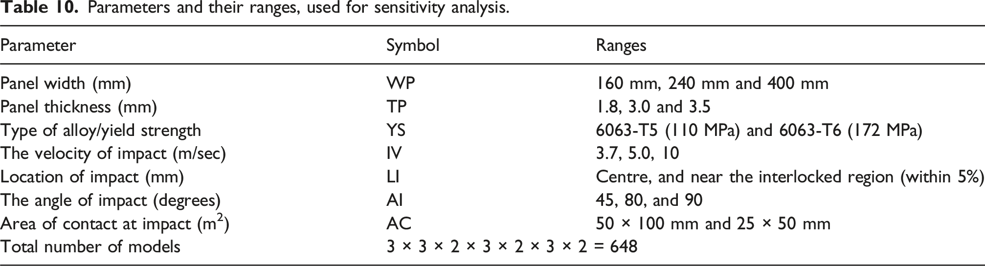
Parameters and their ranges, used for sensitivity analysis.
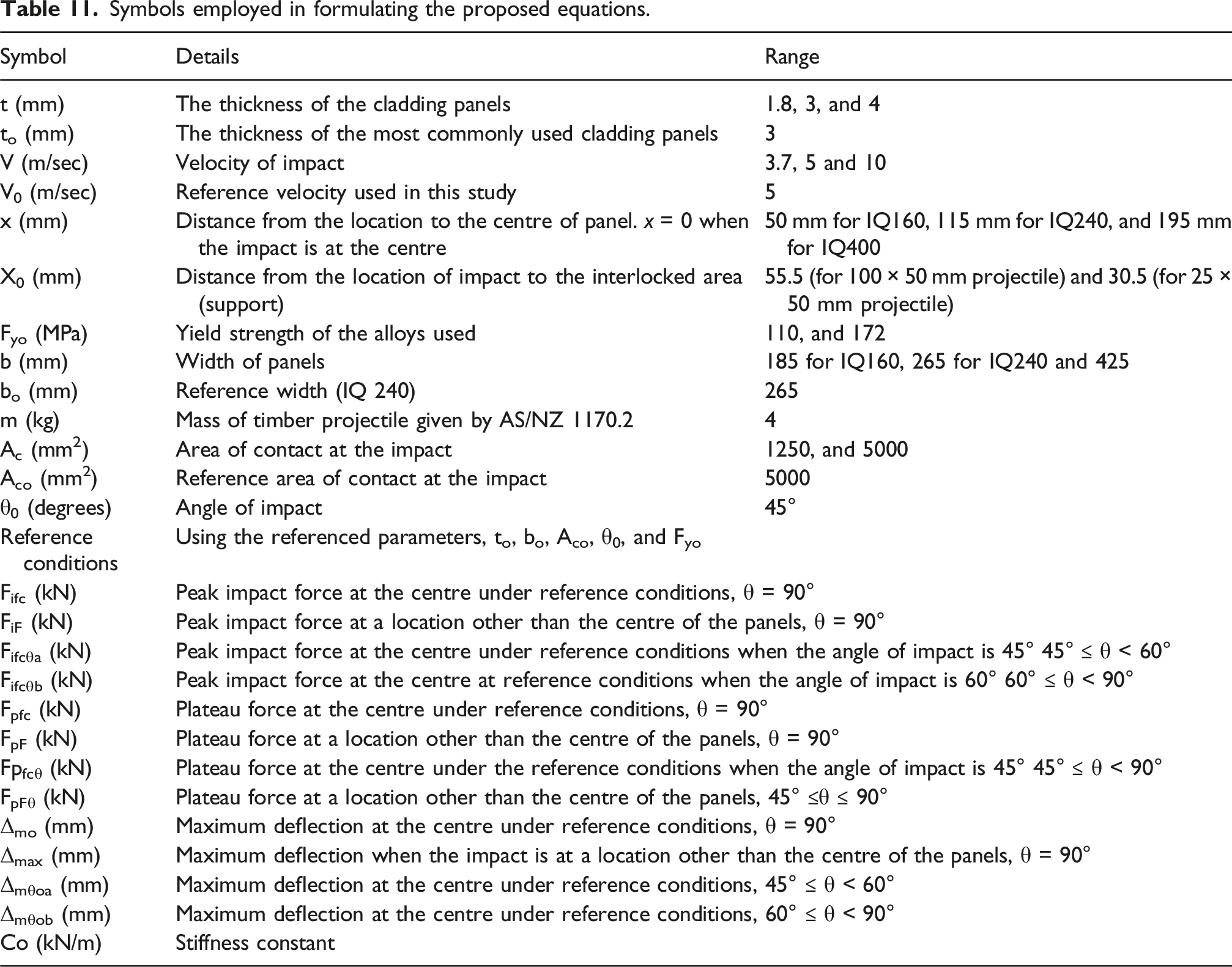
Symbols employed in formulating the proposed equations.
Proposed equations
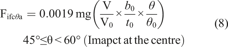
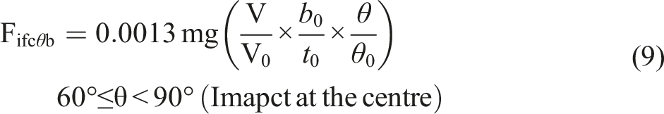
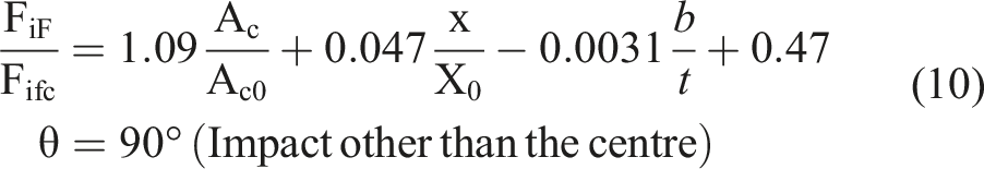
Peak impact force
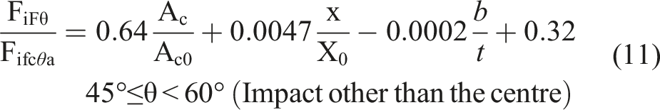
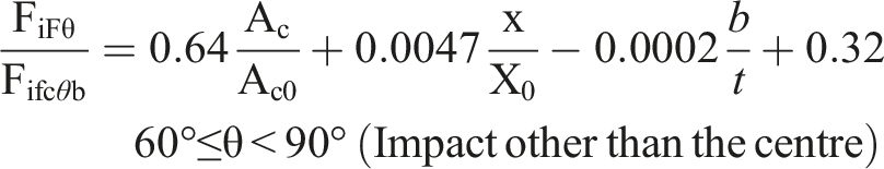
Equations were developed to describe the behaviour of interlocked panel systems across various parameter ranges, keeping in mind achieving the highest value of R2 (above 90%). To enhance prediction accuracy for impacts occurring at different angles, separate equations were proposed, each designed to address specific ranges of the angle of impact. The regression equations for the prediction of the impact force at various angles are given in equations (7)–(11). The values of R2 obtained for all the proposed equations were above 90%. Various symbols used in these proposed equations are given in Table 11.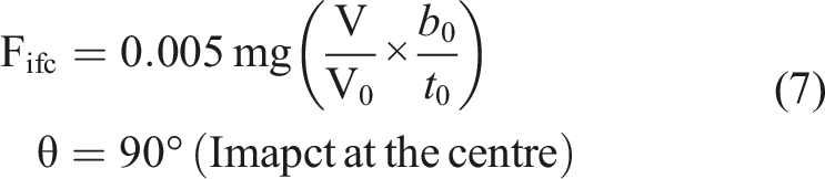
Plateau force
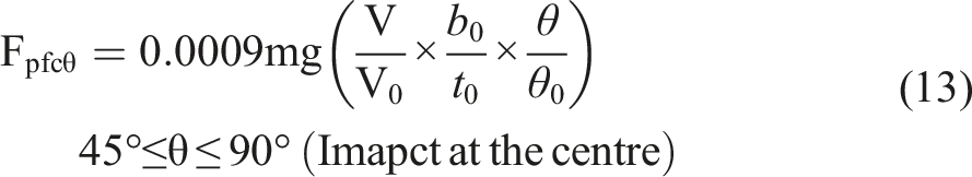
The regression equations for the prediction of the plateau force at various angles are given in equations (12)–(15). The values of R2 obtained for all the proposed equations were above 90%. Various symbols used in these proposed equations are given in Table 11.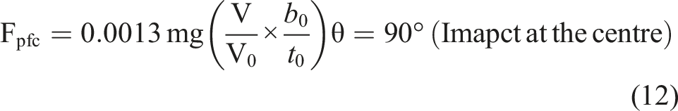
Maximum deflection
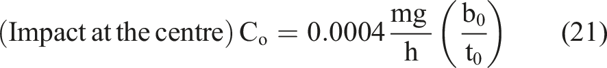
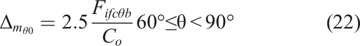
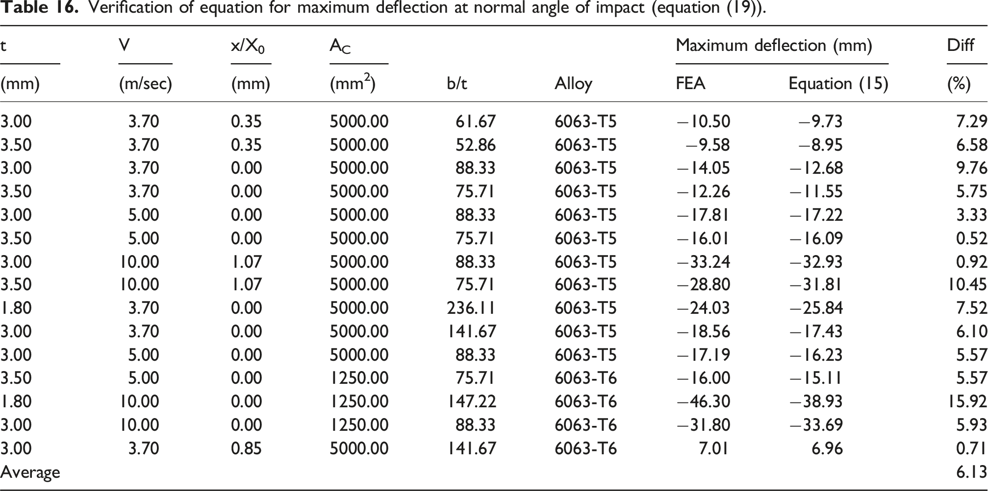
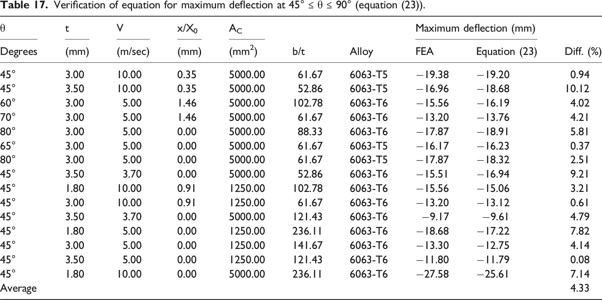
The regression equations for the prediction of the maximum deflection at various angles are given in equations (16)–(23). Similar to the initial peak force and the plateau force, the values of R2 obtained for all the proposed equations were above 90%. Various symbols used in these proposed equations are given in Table 11.

Equation (19) gives the values of deflection when the location of the impact is other than the centre at the normal angle of impact.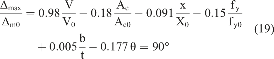
For the angle of impact other than the normal, the values of maximum defection at the centre are given by equations (20)–(23).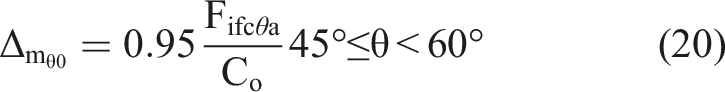
Equation (17) gives the values of deflection when the location of the impact is other than the centre at an angle other than normal.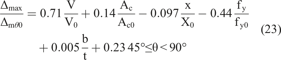
Verification of the proposed equations
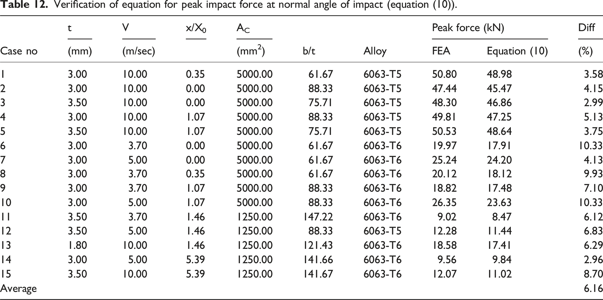
Verification of equation for peak impact force at normal angle of impact (equation (10)).
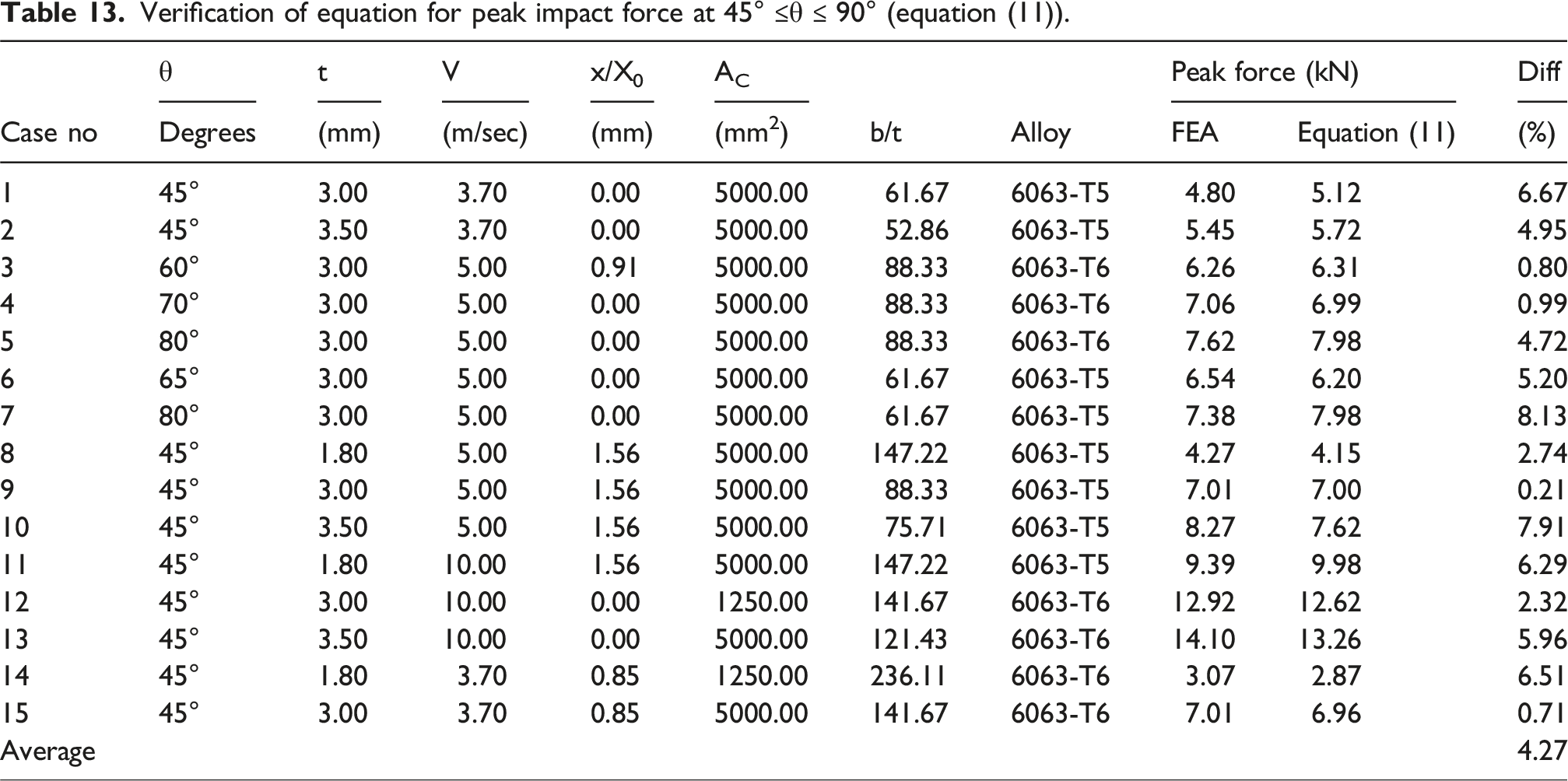
Verification of equation for peak impact force at 45° ≤θ ≤ 90° (equation (11)).
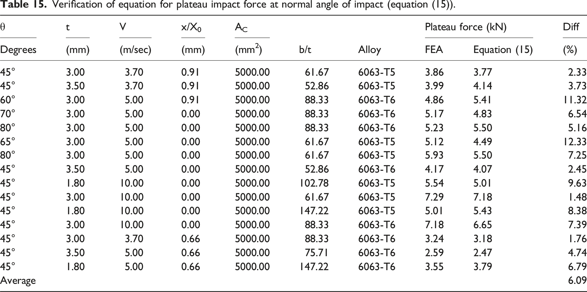
Verification of equation for plateau impact force at normal angle of impact (equation (14)).

Verification of equation for plateau impact force at normal angle of impact (equation (15)).
Verification of equation for maximum deflection at normal angle of impact (equation (19)).
Verification of equation for maximum deflection at 45° ≤ θ ≤ 90° (equation (23)).
Conclusions
This paper presents the experimental and numerical studies conducted to examine the response of extruded aluminium cladding panels (both single and interlocked) under impact loading. Additionally, a comprehensive numerical model was developed and validated to analyse the impact response of the extruded aluminium panels. A parametric sensitivity study was performed to identify key factors affecting the panel’s impact behaviour. Based on these findings, regression equations were formulated to accurately predict the panel’s performance when subjected to timber projectile impacts.
The findings of this study can be summarized as follows: (1) From the experimental study, it was found that the impact history reveals four distinct phases: peak, vibration, plateau, and unloading phase. Interlocking panels would panels increase the initial impact force and plateau force while reducing maximum deflection. No residual deflection was found given the ranges of parameters considered. (2) A robust model for simulating dynamic impact on an aluminium cladding can be developed by employing shell elements, integrating a piecewise linear plasticity model, and considering fracture strain for ductile metals. Incorporating factors such as frictional effects, and deformable projectile modeling can further enhance the model’s accuracy and comprehensiveness. (3) From both the experimental and numerical simulations it was found that the peak impact force was fundamentally influenced by two key factors: impact energy and contact stiffness. Impact energy, a crucial determinant, is predominantly affected by the velocity of impact. Additionally, contact stiffness plays a significant role, and it is influenced by the cross-sectional properties and the material properties of the panels, the location of impact, as well as the contact area, including projectile dimensions and the angle of impact. (4) The plateau force, on the other hand, was primarily influenced by global stiffness, a characteristic determined by three main parameters: the thickness of the panel, the width of the panel, and the imposed boundary conditions. These parameters collectively contribute to shaping the response of the system, with the thickness and width of the panel influencing the overall stiffness, and the boundary conditions further modulating the plateau force during impact events. (5) Maximum deflection is primarily influenced by parameters affecting the stiffness of the panel and the distribution of forces upon impact. Thicker plates contribute to reduced deflection due to their higher stiffness, followed by profile width, impact velocity, angle of impact, impact location, and contact area, which collectively affect the panel’s ability to resist deformation and distribute forces effectively, thus determining the extent of maximum deflection. (6) The proposed prediction equations proved to be a more effective alternative to experimental testing. Validation showed that the predicted values from the regression equations differed by less than 10% for peak impact force and maximum deflection, and by less than 12% for plateau force, when compared with numerical model results, confirming their accuracy. Therefore, it was concluded that the prediction equations closely match the numerical outcomes and can be confidently used to estimate the dynamic impact performance of extruded aluminium panels.
Recommendations
The experimental testing conducted on extruded aluminium panels was limited to low-impact velocities due to constraints imposed by the laboratory apparatus. Consequently, the equations proposed for these extruded panels are based on the data obtained from low-velocity impact. It is recommended to validate the applicability of the proposed equations for situations involving high-impact velocities in future studies.
Footnotes
Acknowledgments
The authors are thankful to Mr Joe Barletta and Mr Michael O’Grady (Valmond and Gibson pty ltd), for providing the extruded aluminium panels that were used in this study. They are also thankful to Mr Chuen Yiu Lo (Senior Technical Officer at Griffith University) for providing technical support for establishing the test setup.
Funding
The authors received no financial support for the research, authorship, and/or publication of this article.
Declaration of conflicting interests
The authors declared no potential conflicts of interest with respect to the research, authorship, and/or publication of this article.