
Abstract
Stay cables in cable-stayed bridges are subjected to various types of dynamic excitation mechanisms under environmental loads. The excited vibrations can have a large amplitude because of low vibration frequencies and small inherent damping of cables. As cables become longer (the longest cables are around 600 m in cable-stayed bridges with a main span of 1000 m), more modes are vulnerable to wind and rain-wind induced vibrations, posing challenges to vibration mitigation. This paper presents a comprehensive review of recent advances in stay cable vibration mitigation, including theoretical modeling of cable damping system and techniques for enhancing multimode damping. Recent results on cable damping measurements, understanding of cable vibrations, and relevant aerodynamic countermeasures are also recalled. The reflections can provide guidance for cable vibration control design of cable-supported bridges and for the maintenance/upgrade of cable vibration mitigation system of existing bridges.
Introduction
Stay cables are crucial components of cable-stayed bridges (Gimsing, 1983). The last two decades have witnessed a rapid increase in the number and the length of stay cables along with the popularity and development of cable-stayed bridges. Cables are subjected to various types of dynamic excitation mechanisms under environmental loads (Xu, 2013). The excited cable vibrations can have a large amplitude owing to their large transverse flexibility and extremely low inherent damping. Cable vibrations jeopardize the long-term safety of themselves and also the serviceability and life of the whole bridge (Abdel-Ghaffar and Khalifa, 1991).
Cable vibration mitigation is a well-known topic in bridge engineering (Virlogeux, 1999). It is considered as one of the challenges in the development of long-span bridges (Xiang and Ge, 2011). Three concepts have been widely used for cable vibration mitigation, i.e., structural design to eliminate internal excitation, aerodynamic countermeasures to reduce external excitation, and vibration energy dissipation/absorption using mechanical devices. The topic is of great interest in the fields of structural engineering, wind engineering and vibration control. Distinguished from other structural control problems (Spencer Jr and Nagarajaiah, 2003), it has unique features including various excitation mechanisms and multiple modes in a wide frequency range prone to vibrations. Hence, the problem is particularly challenging but of wide applications in practical design and maintenance. In this context, cable vibration control has gained extensive attention in the last decades.
There already exist several review works on cable vibration and control. Fu et al. (2004) and Hu et al. (2004) summarized the observed wind-induced cable vibrations and general vibration mitigation measures. Virlogeux (2005) provided a comprehensive introduction of cable vibrations from the wind loads, cable inherent damping, to vibration models, and briefed the countermeasures in practice. Kumarasena et al. (2005) focused on vibration suppression requirements for various excitation mechanisms and presented design methods for viscous dampers and discussed effects of cross-ties. Caetano (2007) detailed cable vibrations and introduced the damping effects of a cable with a viscous damper, together with several cases of cable vibration and suppression. Fujino (2002) and Fujino et al. (2012) reviewed cable vibration and control with a focus on the Japanese practice.
In the last decade after the aforementioned review works, significant advances have been made in cable-stayed bridges. Correspondingly, the largest length of cables increases, as shown in Figure 1. When the first cable-stayed bridge with a main span over 1000 m long, i.e., the Sutong Bridge, was opened to traffic in 2008, the length of stay cables first exceeded 500 m. Subsequently, a number of large-span cable-stayed bridges have been constructed. The longest cable of the Third Bosphorus Bridge, which adopts a hybrid cable-supporting system, is 597 m (Guesdon et al., 2020). The longest cable will exceed 600 m in the Changtai Yangtze River Bridge, and soon reach 649 m in the Ma’anshan Yangtze River Bridge. As cable length further increases and thus cable fundamental frequency decreases, the number of cable modes in the frequency range sensitive to rain-wind induced vibrations (RWIVs) increases significantly. Meantime, the wind speed corresponding to high-mode cable vibrations induced by vortex shedding decreases. These vibration characteristics of long cables have been manifested in field observations, e.g., on the Sutong Bridge (Ge and Chen, 2019; Liu et al., 2021c), the Hu-Su-Tong Yangtze River Bridge (Hu et al., 2020) and a cable-stayed bridge in Korea (Kim et al., 2022). Development of the largest length of cables in cable-stayed bridges.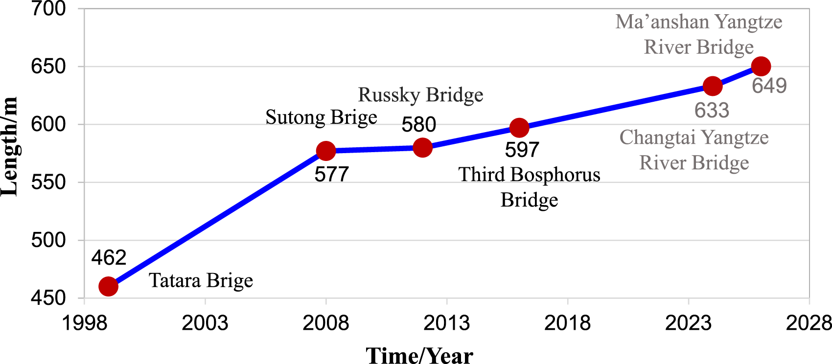
Lately published review papers on cable vibration and control have paid attention to different aspects of the topic. Jafari et al. (2020) presented a comprehensive review of wind-induced vibrations, Javanmardi et al. (2022) focused on vibration control techniques and devices, Chen et al. (2022) pointed out three main problematic cable vibrations to be resolved at present, and Caetano (2021) summarized fundamentals of cable dynamics, wind-induced cable vibrations, and also introduced common mechanical dampers for cables. In contrast, the present paper focuses on the development of schemes and techniques for supplementing cable damping and theoretical investigation of the damped system, with emphasis on the recent practice particularly in China. The recent advances in cable vibrations and aerodynamic measures will also be covered. The reflections on these developments could provide guidance for vibration mitigation design of the cable-stayed bridges under construction and for the maintenance and upgrade of the vibration suppression system of existing bridges. Besides, this review is useful to the development in vibration control of cables with new materials (Wang and Wu, 2011a, 2011b; Yang et al., 2015, 2020).
The remainder of this paper starts with the advances in understanding cable vibrations, along with developments in aerodynamic countermeasures. Subsequently, cable damping estimate methods are summarized and the recent measurement results of cable inherent damping are discussed. Damping analysis of a cable with mechanical dampers is then introduced. Strategies and techniques for improving cable damping in a wide frequency band are presented. The paper is closed by a summary together with an outlook.
Cable vibration and aerodynamic countermeasure
Cable vibration mechanisms/characteristics and the effectiveness of aerodynamic measures are usually investigated through wind tunnel tests and computational fluid dynamics (CFD) simulations. They are thus reviewed together in this section. It is noted that the purpose here is not to provide a complete review of cable vibrations but to discuss the advancement in aerodynamic countermeasures. A review of cable vibrations can be found in Jafari et al. (2020).
RWIVs
Rain-wind induced vibrations have been the main concern in cable vibration mitigation design. Since first observed on the Meikonishi Bridge (Hikami and Shiraishi, 1988), such vibrations have been observed on many bridges around the world, e.g. the Higashi-Kobe Bridge (Saito, 1994), the Yangpu Bridge (Gu et al., 1998), the Eramus Bridge (Geurts et al., 1998), the Alamillo Bridge (Casas and Aparicio, 2010), the Fred Hartman Bridge (Main and Jones, 2000; Main et al., 2001; Zuo and Jones, 2010; Zuo et al., 2008a), the Dongting Lake Bridge (Ni et al., 2007; Wang et al., 2003b), the Veterans’ Memorial Bridge (Phelan et al., 2006), and the Sutong Bridge (Ge and Chen, 2019). Based on these field observations, along with full-scale measurements (Matsumoto et al., 2003) and wind tunnel tests, general characteristics of RWIVs are well-established (Caetano, 2021; Matsumoto et al., 1998), e.g., vibration frequency in 0.3 Hz–3 Hz, corresponding wind speed in the range of 5–20 m/s, and cable inclination angle in between 20° and 45° and so on.
To understand the excitation mechanism of RWIVs of stay cables, wind tunnel tests have been conducted to investigate the influences of various factors. The relative position of upper rivulet to wind direction was found of significant importance and vibrations of the cable models exhibit the galloping type (Gu et al., 2002). Gu and Du (2004) further examined influences of wind speed, cable inclination, and cable frequencies. Apart from two-dimensional (2D) measurements on the vibration in vertical plane, three-dimensional (3D) experiment setups were developed to include the horizontal vibrations (Zhan et al., 2008). Using 3D experimental setups, Xu et al. (2006) measured drag and lift coefficients of inclined circular cylinders with an artificial rivulet. Novel techniques were used to track the moving rivulet, e.g., digital camera (Gao et al., 2021b; Li et al., 2015). The coupling of upper rivulet and cable vibration was further understood (Jing et al., 2015, 2017) as that the oscillating upper rivulet induces the boundary layer to attach on the cable and generates aerodynamic forces. Flow around an inclined cable with moving rivulet was characterized in Wang et al. (2005b), including the vortex formation and strength. Wake dynamics was further included in the coupling beside cable vibrations and rivulet dynamics (Gao et al., 2021b). Ge et al. (2018) refined analyses of the influences of rainfall intensity and raindrop size, and identified two unfavorable environment states. Gao et al. (2018) was able to excite RWIVs in three modes of a flexible cable by guiding water rivulets on the cable in wind tunnel tests and proposed bubble burst as a possible excitation mechanism. Characteristics of the multimode RWIVs were further investigated and compared with vortex induced vibrations (Gao et al., 2019). The excitation mechanism of RWIVs is still an ongoing topic and has received intensive attention. The list of the relevant references herein is by no means exhaustive. A review on RWIVs with emphasis on rivulet dynamics can be found in Gao et al. (2021a).
Based on the measurements of aerodynamic coefficients, rivulet motions and cable vibrations in the wind tunnel tests, analytical models have been developed for RWIVs. Xu and Wang (2003) developed a single degree of freedom model to consider the interaction among moving rivulet, cable vibration and wind for steady vibrations. The equation of motion of the upper rivulet was further included, leading to a 2DOF model (Wang and Xu, 2003). Gu (2009) established a theoretical model for instability analysis of a 2D sectional rigid model with a moving artificial rivulet and proposed the instability criterion. Based on measured aerodynamic coefficients of a cable using a spatial cable model under 3D flow, Li et al. (2011, 2014) developed a modified galloping model to predict RWIVs. Xu et al. (2008) proposed a framework to estimate the occurrence of RWIVs based on joint wind-rain distribution, a theoretical rain-wind excitation model, and a numerical model of the cable. Zhou and Xu (2007) and Wang and Xu (2009) integrated the rain-wind excitation model with a numerical model of cables, conducted parametric study, and showed that damping can suppress cable RWIVs.
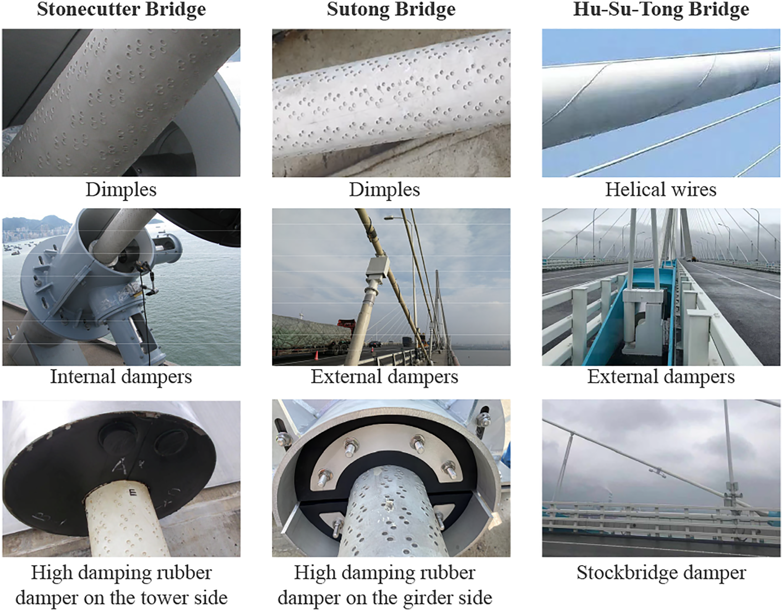
Two typical countermeasures have been validated in mitigating RWIVs, i.e., cable surface treatments and supplemental damping. As shown in Figure 2, cable surfaces with dimples or thin helical wires are used to prevent the formation of rivulets, e.g., on the Sutong Bridge and the Stonecutter Bridge (Figure 3). Du et al. (2003) studied the effects of helical wires in destroying the rivulet and found that when the wire has a diameter larger than 1 mm (Figure 2), the rivulet can be destroyed and the interval distance of wires need to be smaller than 30 cm to fully suppress RWIVs. Li and Lin (2005) compared the effectiveness of the helical wire cable, the axially protuberated cable, and the cable with elliptical discrete thick plates. Liu et al. (2018, 2019b) investigated the transverse aerodynamic force and stability of cables with helical wires, and found that in a range, increase in the diameter of the helical wires and reduction in the interval distance, can increase the roughness of the cable surface and hence reduce cable vibrations; while in the case of high Reynolds number wind induced vibration, increase in helical wire diameter can increase model vibration amplitude. With a high-precision rain simulator, Chang et al. (2016) found that helical wires performed very well in controlling RWIVs of a cable with a diameter of 139 mm while had limited effects when the cable diameter is 200 mm. Other methods for cable surface treatments have also been studied in wind tunnel (Gao et al., 2022a; Kleissl and Georgakis, 2011; Sun et al., 2022d). According to Gu and Du (2005), a damping ratio over 0.5% can reduce RWIVs, which has also been confirmed by using a numerical model of cable-viscous damper and an analytical model of rain-wind excitation (Li et al., 2007b). Based on 4 years monitoring data, Ko and Ni (2003) and Chen (2005) also showed that when the supplemental damping ratio is larger than 0.5% effective suppression of cable RWIVs can be achieved. Liu (2010) and Liu et al. (2015) outlooked the key factors governing cable RWIVs are to be further investigated, including motion of rivulet, Reynolds number effect, and the vibration control strategy. Typical aerodynamic countermeasures: (a) cable surfaces with dimples, and (b) thin helical wires for suppressing rain-wind induced vibrations; (c, d) thick helical wires for suppressing vortex induced vibrations (Liu et al., 2021c) and wake-galloping vibrations (Fujino et al., 2012). Cable vibration mitigation with combined techniques.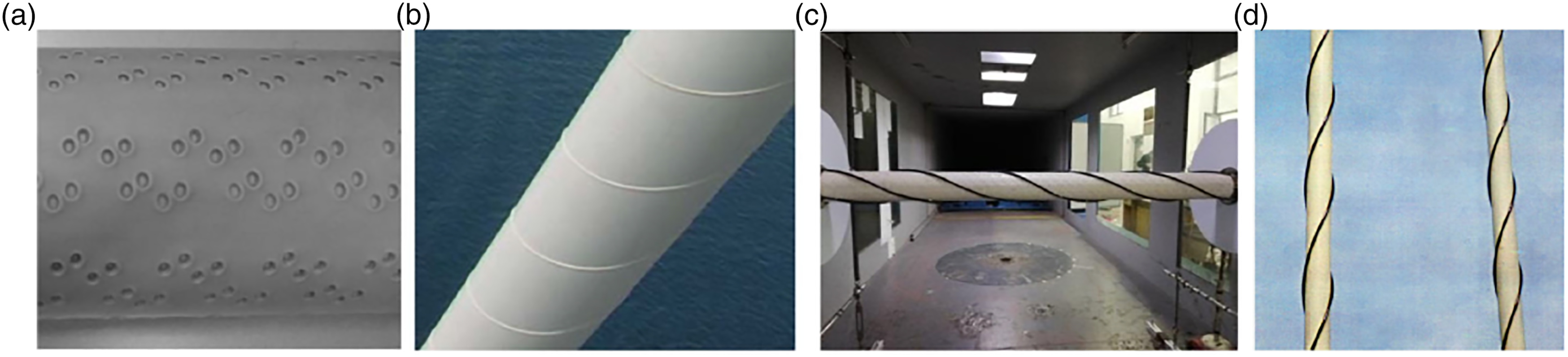
Vortex-induced vibrations
Vortex-induced vibrations (VIVs) of stay cables are also well-known (Matsumoto et al., 2001). The vibration is characterized by limited amplitude and could be suppressed with a small amount of damping. Cable VIVs are often concerned in the bridge construction phase when the cable dampers are not installed (Kumarasena et al., 2005). While the understanding of cable VIVs was mainly established using segmental models, Chen et al. (2013a) investigated their spatial characteristics by simulating a full flexible cable under different wind profiles using CFD techniques. Zhou et al. (2019d) proposed a modified wake oscillator model to numerically simulate a full cable under vortex shedding effects.
As cables become longer and their fundamental frequencies become lower, vortex-induced high-mode vibrations occur under relatively low speed wind conditions. High-mode cable VIVs were identified from the monitoring data of existing bridges (Chen et al., 2019b; Kim et al., 2022; Liu et al., 2020c). Particularly, for long cables (probably longer than 300 m), even with external dampers installed, VIVs appear with observable amplitude, in very high frequencies (can be over 10 Hz), as observed on the Sutong Bridge and the Hu-Su-Tong Bridge (Liu et al., 2021c). Mode shapes of the dominant vibration modes have a node close to the position of the external damper and hence nearly no supplemental damping is supplied to the vibration modes by the damper.
Correspondingly, a number of aerodynamic measures have been proposed for suppressing cable VIVs, e.g., by traditional cable surface treatments or by novel flow control techniques (Chen et al., 2013b, 2019a, 2020c). Through wind tunnel tests of cables with helical wires of different diameters (Li et al., 2018; Liu et al., 2021c), it was found that the helical wires with a small diameter (e.g., less than 2 mm) for mitigating RWIVs can not suppress high-mode VIVs. For effective suppression of cable VIVs, the diameter of the helical wires needs to be around 10 mm (Liu et al., 2021c), see Figure 2(c).
Galloping
The observed galloping of stay cables include dry galloping, ice/snow accumulation induced galloping, and wake galloping. When there exists a component of wind velocity not normal to the axis of a dry inclined cable, dry galloping may happen. According to a series of testing described in Kumarasena et al. (2005), with a small amount of damping (damping ratio larger than 0.3%), dry galloping of inclined cables is not significant and hence the dry cable instability should be suppressed. However, the mechanism of cable dry galloping is not crystally clear. Cheng et al. (2008b) and Cheng et al. (2008a) considered the mechanism similar as that for Den Hartog criterion. Matsumoto et al. (2010) further explained that the dry galloping is caused by mitigation of Karman vortex shedding.
Cable vibrations with a large amplitude induced by ice/snow accumulation have been observed in several cases when the cables are not equipped with dampers, e.g., the Dubrovik Bridge (Savor et al., 2006). The ice/snow-coating changes the shape of cable section and hence induces galloping-type vibrations. These vibrations can be suppressed by preventing ice/snow accumulation or supplementing damping (Savor et al., 2006). Similarly, decoration and lighting systems attached to stay cables also change the shape of cable cross-section and hence induce galloping-type vibrations (An et al., 2021, 2022; Tang et al., 2022; Zheng et al., 2021), which currently becomes a big concern (Chen et al., 2022). Careful aerodynamic examination is required before the installation of such attachments on cables.
Wake galloping vibrations may occur for a group of cables arranged in close distance (Deng et al., 2021a; Tokoro et al., 1999). In cable-stayed bridges, this type of vibrations can be prevented in structural design, while in suspension bridges, suspenders are often designed to be composed of two or four cables and wake galloping becomes an important issue, as observed on the Xihoumen Bridge (Deng et al., 2021b; Li et al., 2019a). Wake-induced vibrations of cables in the rear of neighboring cables or the bridge tower have been invesitgated in wind tunnel (Chen et al., 2020d; Li et al., 2019b). Such wake vibrations may be suppressed using helical wires with relatively a large diameter (Fujino et al., 2012; Li et al., 2018) (Figure 2(d)) and spacers (Wen et al., 2018).
Support motion induced cable vibration
Anchored to the bridge girder and tower, cables are also subjected to vibrations excited by the girder/tower vibrations. Parametric vibrations are typically such vibrations need to be avoided. Earlier stability analysis of parametric vibrations was based on a cable with axially movable ends (Li et al., 2008a; Lilien and Da Costa, 1994; Liu et al., 2020b). The mechanism and stability boundary were further investigated with the inclusion of bridge girder dynamics using reduced-order models (Xia and Fujino, 2006) and numerical models (Gattulli et al., 2005; Xia et al., 2011). Aerodynamic damping has also then considered in the parametric vibration analysis (Xia et al., 2010), leading to the wind speed-dependent stability condition.
Field measurements on the International Guadiana Bridge showed clear cable-deck interactions, corresponding to 1:1 internal resonance (Caetano et al., 2008), which was also verified by the finite element model (FEM). Similarly, field measurements of cable and corresponding deck vibrations on the Fred Hartenmen bridge also showed the coupling cable-girder/tower vibrations (Liu et al., 2013b) where a reduced-order model of a cable with lateral movable support was proposed to describe the underlying mechanism.
The support-motion induced cable vibrations can be prevented in structural design to avoid internal resonance. However, for large-span cable-stay bridges, vibration frequencies of both girder and cables are low and close-spaced, and it might be difficult to separate the girder and cable frequencies completely. In these scenarios, adding cable-deck dampers or active damping is effective to reduce the vibration amplitude (El Ouni et al., 2012; Xue and Liu, 2009). For examples, transverse dampers have also been shown effective in suppressing parametric vibrations of cables (Chen and Li, 2007), and Sun et al. (2001, 2003) proposed a passive-mass-spring system for the same purpose.
Cable inherent damping
Beside aerodynamic measures, supplementing damping is another viable method for cable vibration control. For cables in long-span bridges, a combination of these two methods becomes common practice, as shown in Figure 3. In this section, available studies on cable damping measurements and the results are recalled.
Damping measurements
It is of significant importance to measure cable inherent damping and the supplemental damping when dampers are installed, e.g., it is a crucial factor in evaluation of aerodynamic performances by CFD analysis and wind tunnel tests. Practically, it is still a challenging issue, particularly for long cables and higher vibration modes. The key is cable vibration excitation. There are four methods (see Figure 4) to excite cable vibrations for damping estimate, as described below. Cable vibration excitation methods: (a) manual excitation; (b) excitation using motor mounted on bridge deck (Wang et al., 2022a); (c, d) vibrators respectively used in Chen et al. (2020b) and Kye et al. (2019); (e) bridge deck excitation (Casas and Aparicio, 2010).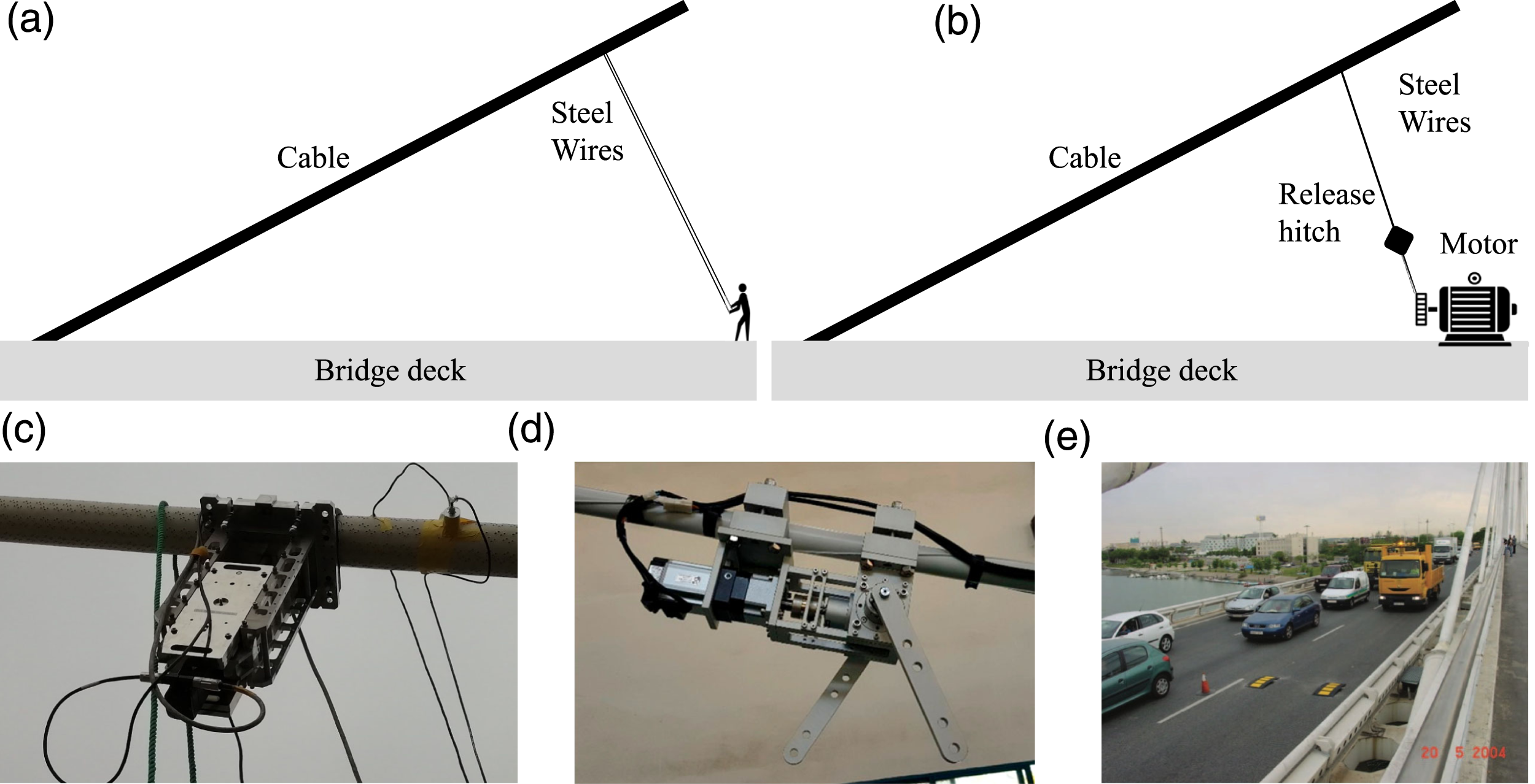
Ambient excitation
It is common nowadays to have accelerometers and other sensors installed on cables for vibration monitoring. Frequencies can be easily extracted from the acceleration measurements under ambient excitation. Damping identification from those cable responses under ambient excitation, however, is still a topical area. For evaluating damping performance of external dampers on cables of the Dongting Lake bridge, Ko et al. (2002) was able to extract modal damping of 40 cable modes, by fitting the peaks of response spectra.
Cable vibrations under environmental excitation involve multiple modes, the vibration amplitude is generally small, and the identified damping has contributions from aerodynamic damping. Therefore, damping estimated from ambient vibrations shows relatively large variations (Zhou et al., 2022b). The estimated damping is often considered less reliable as compared to those obtained from free decay tests. A careful selection of the monitored response, e.g., by using machine learning method (Shang et al., 2022) to obtain free decay like responses, could be a promising means to improve the damping identification from daily monitoring data of cable vibrations.
Manual excitation
Manual excitation is arguably the most widely used method for cable damping estimate, both in field tests and full-scale tests in cable manufactory, because the convenience and effectiveness. One person or a group of persons directly excite the cable manually, as in Figure 4, or using wires in the case of field tests. The method was used in the test campaign to evaluate performance of full-scale dampers on a 220 m long cable (Sun et al., 2008). Because of the manual force is limited, vibration in the first two modes are extremely difficult to excite in field tests. Similarly, it is nearly impossible to excite cable vibrations with a frequency higher than 3 Hz. In the case of the Sutong Bridge, it succeeded in exciting vibrations from the 3rd mode to a mode with a frequency less than but close to 3 Hz (Chen et al., 2020b).
The performance of manual excitation in lower modes can be improved if excitation force is applied farther from the cable-deck anchorage. For example, manual excitation was performed by a person in a basket hanging from a crane in the case of the Alamillo Bridge in Spain (Casas and Aparicio, 2010).
Cable vibrators
As manual excitation becomes less effective for long and heavy cables and for high-frequency cable modes. Cable vibrators are highly desirable. In field tests, He et al. (2002a) used a motor drive system with variable frequency fixed on bridge deck and then connected to the cable using a wire. The wire connected to the motor eccentrically provides excitation force to the cable when the motor rotates. A device to release the wire suddenly has been included to let the cable decay freely after excitation. This kind of excitation system has been used on other bridges in field tests (Wang et al., 2022a). Owing to the flexible connection between the cable and the motor, the excitation force is not precisely sinusoidal and thus multimode cable vibrations are often excited. Besides, deformation of the whole bridge under living loads could also influence the performance.
To obtain cable vibration response in a single mode and also to excite high-mode (e.g., modes with a frequency above 3 Hz) cable vibrations, a vibrator installed on the cable was used in field tests by Chen et al. (2020a, 2020b). The vibrator includes a base that can be mounted on the cable and a movable part that is driven by a linear motor. A signal generator along with a control unit controls the motor to drive the movable mass according to prescribed motions. The inertial force of the movable part then drives the cable to vibrate. Purely single mode vibration response can be obtained using such a vibrator, while the installation is relatively inconvenient and the installation location needs adjustment when different modes are targeted. In the case of cables over 500 m on the Sutong bridge, cable vibration with frequencies higher than 5 Hz has been excited. It has also been used on the Stonecutter Bridge, where cable vibration with frequencies over 20 Hz has been excited (Su et al., 2010; Yamazaki et al., 2010). Kye et al. (2019) also developed a vibrator mounted on the cable using rotating motor that applies inertial force for excitation. The vibrator performed well in experiments of a 44 m long cable with dampers.
Bridge deck excitation
Cable vibrations can also be excited indirectly by bridge girder vibrations. Obstacles can be placed on the bridge deck, and the impulse forces generated when traffic and trucks pass over the obstacles can excite the bridge girder thus leading to cable vibrations. This method has been used on the Alamillo Bridge in Spain (Casas and Aparicio, 2010). However, for large span bridges, the excitation of bridge girder can be much more difficult than the excitation of the cable itself. Besides, the method would also interrupt the transportation.
Measurement results
The level of inherent damping of stay cables is suggested in several specifications and recommendations on cable or cable-supported structure design. PTI DC45.1-18 recommends intrinsic damping ratio of stay cables to be in the range from 0.05% to 0.3%. The Chinese specification (JTG/T 3360-01–2018) adopts a damping ratio of 0.1% for cables/suspenders without any dampers. While in Setra 2002 and fib Bulletin 89, varied damping ratios are recommended according to the cable technology. An intrinsic damping ratio of 0.08%–0.15% is recommended for cables composed of individually protected wires/strands, 0.015%–0.08% for parallel wire/strand cables, and 0.008%–0.08% for cement grouted cables. Clearly, the intrinsic damping ratio of stay cables varies in a relatively large range, and it is always desirable to acquire more field testing data.
In recent years, there have been more measurements on stay cables, particularly of large length. The measured cable inherent damping data is collected and presented in Figure 5. In the figure, the measured damping ratios corresponding to long cables (e.g., longer than 300 m) are indicated using hollow markers, and the corresponding cables are mostly composed of parallel wires. The available data covers quite a wide frequency range, and it is seen that as vibration frequency increases, the cable inherent damping tends to decrease. In particular, for high-mode high-frequency vibrations, the damping ratio is less than 0.05%, close to the lower bounds of cable intrinsic damping as recommended in the specifications, which is inadequate to suppress high-mode VIVs if no dampers are attached to the cable or the damper fails in controlling such vibrations. The data points for long cables (the labeled four cables in the figure) are fitted to obtain an approximate damping-frequency (ζ-f) relation ζ ≈ 0.3517/(f + 3.534), showing a trend of decreasing damping with respect to increasing vibration frequency. Measurement results of cable inherent damping collected from the literature.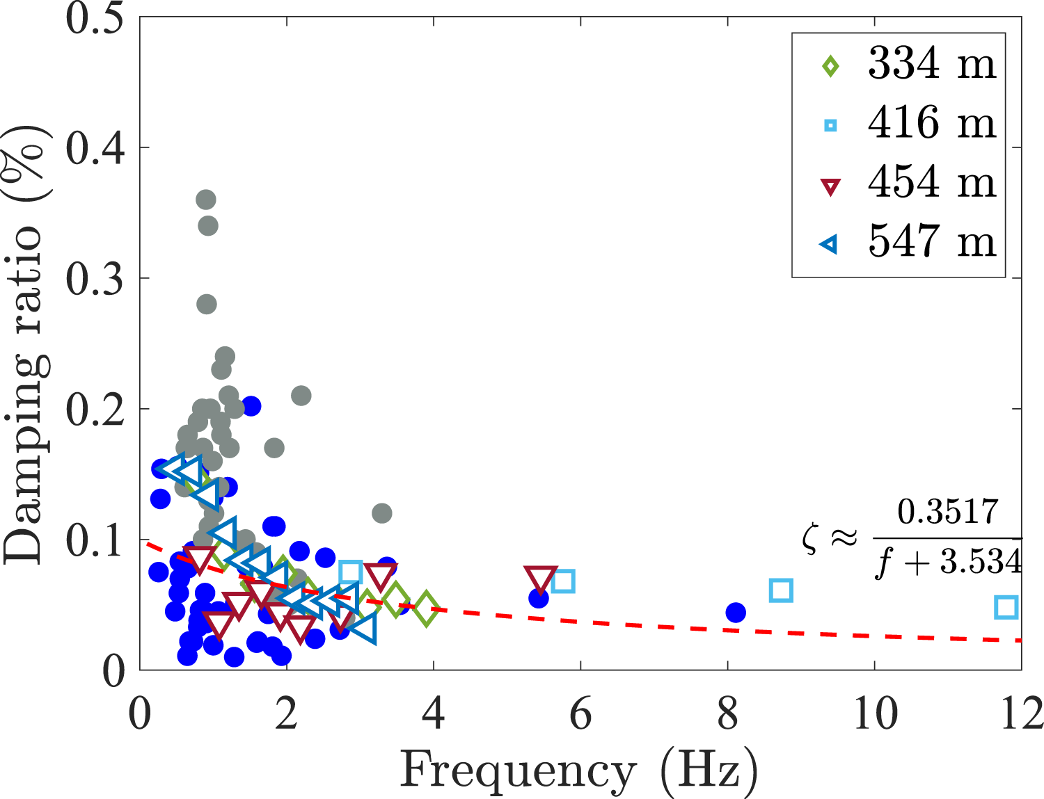
Damping of a cable with mechanical dampers
Theoretical development
The study of a cable attached with a mechanical damper dates back to 1980s, when Kovacs (1982) pointed out the existence of an optimum damper size and presented empirical expressions for the optimum damping ratio and corresponding damper size of the fundamental mode. Later, practical design curves were pursed to estimate the additional damping via numerical eigenvalue analysis (Yoneda and Maeda, 1989). Pacheco et al. (1993) was able to establish a general relation between modal damping and damper size from numerical results in terms of dimensionless cable and damper parameters, leading to a “universal curve” for design. The curve is applicable to lower modes of a cable with a damper near its anchorage. The numerical investigations mostly ignored cable sag and bending stiffness which are of importance to cable dynamics (Irvine 1981). Besides, Yoshimura et al. (1989) and Uno et al. (1991) measured smaller attainable damping in field tests as compared to the prediction. Subsequent studies including Pacheco et al. (1993), Mehrabi and Tabatabai (1998) and Tabatabai and Mehrabi (2000), accounted the influences of these factors, using similar numerical methods. Xu and Yu (1998) and Xu et al. (1998) further included cable inclination through a hybrid analytical/numerical method. These studies showed that for the practical range of parameters of most stay cables, influence of cable sag is insignificant, while bending stiffness could significantly affect cable damping. Yu and Xu (1999) and Xu and Yu (1999) formulated a numerical model for cable-damper system analysis considering non-linearity, showing control performance of oil damper on internal resonance and in-planar vibrations. Cable damper design considering both sag and bending stiffness was realized respectively by using a finite different model (Mehrabi and Tabatabai, 1998; Tabatabai and Mehrabi, 2000) and using modal expansion method (Wang and Chen, 2002; Wang et al., 2001). Using the finite difference method, Chen et al. (2002) analyzed damping provided by viscous dampers placed not in the vertical cable plane to both in-plane and out-of-plane modes.
Distinguished from the numerical investigations, Krenk (2000) analytically formulated the characteristic equation of a taut cable with a viscous damper. Cable vibration responses were thereby represented in terms of complex-valued modes and asymptotic expression of close form was obtained for damping estimate. The expression echos the “universal curve” of Pacheco et al. (1993), and has then been widely used in practical design. It is noted that for damping guy cables, similar analytical solution was pursued by Carne (1981). The complex modal analysis method has been widely used to reevaluate the effects of cable sag (Krenk and Nielsen, 2002; Nielsen and Krenk, 2003) and flexural rigidity (Hoang and Fujino, 2007; Main and Jones, 2007a, 2007b). Cable sag is found to reduce damping effect in the first mode of stay cables of practical parameter range while the effect of bending stiffness also depends on boundary conditions (Main and Jones, 2007a), which nevertheless are difficult to determine in practice. Liang et al. (2008, 2009a) showed that bridge girder flexibility has an negative effect on cable damper performance which has also been validated via model tests (Liang et al., 2009b, 2014). Wang et al. (2019a, 2020a) considered both vibrations of bridge deck and tower (with only first mode kept) in dynamic analyses of a cable-damper system.
Parameters pertaining to cable dampers (see Figure 6) are of even more critical importance to the damping of cable-damper systems. The Kelvin model for viscoelastic dampers, e.g., viscous shear dampers for cables, is used to account for damper intrinsic stiffness, first by the numerical method (Yoneda and Shimoda, 1993) and then using the analytical formulation (Fournier and Cheng, 2013; Krenk and Høgsberg, 2005; Zhou and Sun, 2006, 2008c). Damper stiffness is found to decrease the maximally achievable cable damping. Similarly, flexibility in damper support also impairs the damper effectiveness (Huang and Jones, 2011; Xu and Zhou, 2007; Zhou and Sun, 2006); while attached mass to the cable at damper installation slightly increases the supplemental damping (Duan et al., 2005b, 2015; Krenk and Høgsberg, 2005). Considering those damper parameters, the damping expression and thus the universal curve are modified accordingly, which has been further extended to include the frequency-dependency of damper properties, e.g., using fractional derivative models (Krenk and Høgsberg, 2005; Sun and Chen, 2015) and by varying damper parameters for different modes according to experiments (Sun et al., 2022b). Using the analytical formulation and taking into account both cable sag and bending stiffness, Fujino and Hoang (2008) derived the modification coefficients respectively related to sag, bending stiffness, damper stiffness and support flexibility, leading to uniform design formulas. Besides, most dampers behaves non-linearly, introducing amplitude-dependent damping to cables. Using an approximate method, Main and Jones (2002b) obtained explicit relation between cable damping and amplitude for nonlinear viscous dampers. Typical cable dampers and their mechanical models, where k
d
and k denote the stiffness coefficient of the corresponding spring, c
d
is viscous coefficient, φ is loss factor, μN is the kinetic friction force, and M denotes concentrated mass.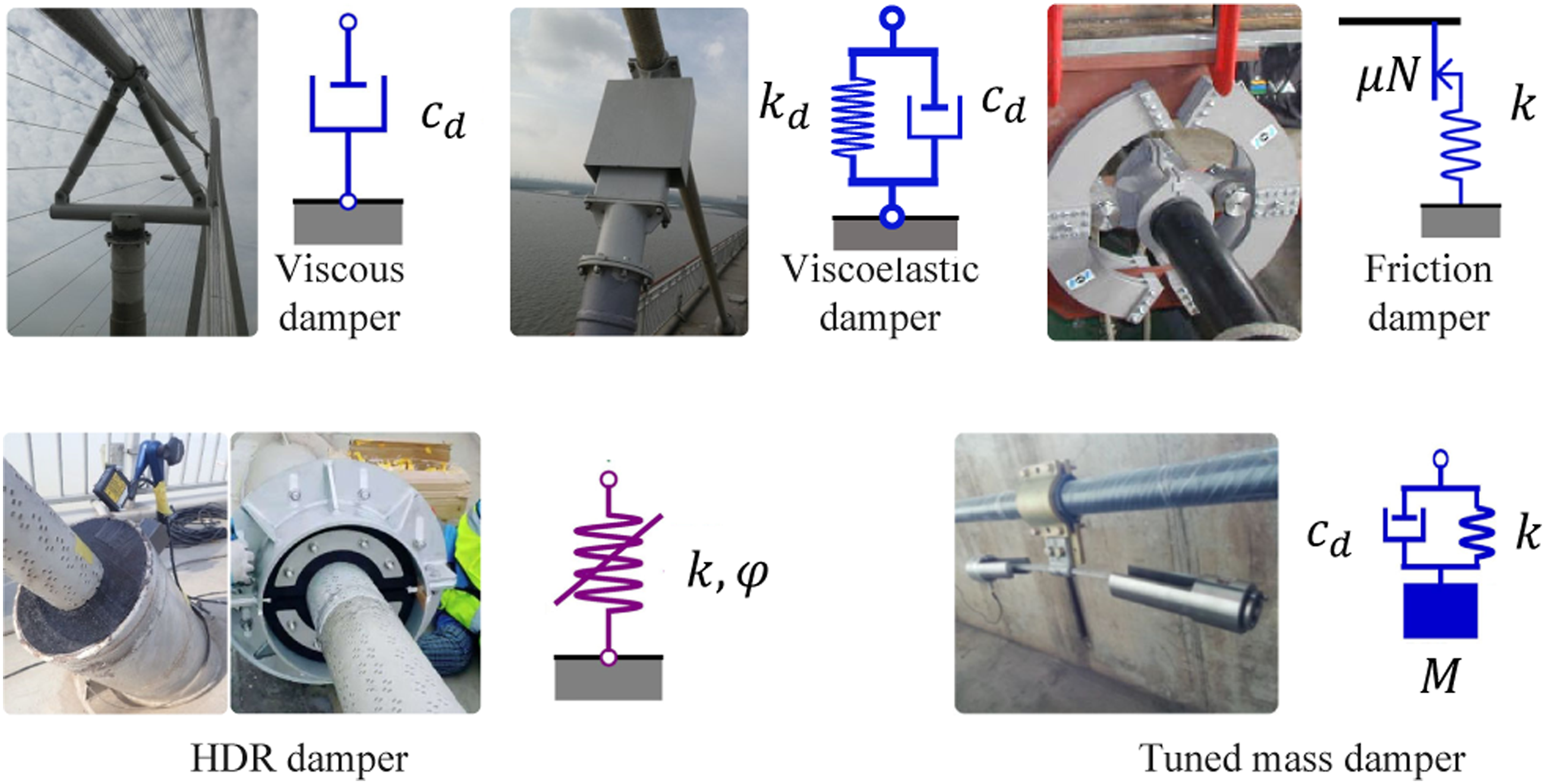
Theoretical analysis of cable-damper system has paid attention to dynamics of the system without limiting the damper location. For different damper locations, cable frequency variations as damper coefficient increasing from zero to infinity can be categorized into three types (Main and Jones, 2002a). Similarly patterns have been found for a tensioned beam with a viscous damper (Main and Jones, 2007a), a cable with a viscoelastic damper (Sun and Chen, 2015; Zhou et al., 2013), and a cable with a negative stiffness damper (Chen et al., 2015).
Although in most cases, it is more convenient to follow the analytical formulation for free vibration analysis of a cable-damper system, an efficient and accurate numerical model is required in a variety of other situations, e.g., for analyzing vibration amplitude under wind loads (Abdel-Rohman and Spencer, 2004). The earliest method was based on modal expansion using analytical modes of a taut string without any attachments (Pacheco et al., 1993). It is necessary to keep a large number of modes for convergence, and hence computation efficiency is relatively low. By including the static deformation of a cable under a point load at the damper location as a generalized coordinate, the number of cable modes required is largely reduced with sufficient accuracy retained (Johnson et al., 2000, 2007). Such a model has been extended to include cable sag and bending stiffness (Johnson et al., 2003; Wang and Chen, 2002) and different boundary conditions (Javanbakht et al., 2019). With those improvements, the modal expansion based model appears to be more efficient as compared to the finite difference model (Chen et al., 2004a; Mehrabi and Tabatabai, 1998) and the vector form finite element method (Ni et al., 2014) which are able to consider all those mentioned cable and damper parameters but need a relatively large number of degrees-of-freedom to precisely assess damping and describe damper location. To maximize computation efficiency, Main (2002) suggested that it is sufficient for convergence by adopting two special mode shapes, respectively corresponding to the free vibration and clamped vibration of a particular cable mode, as shape functions in modal decomposition using Galerkin method for studying cable resonant responses. This idea was developed to solve discrete systems with several viscous dampers (Main and Krenk, 2005), interpreted as interpolating between the solutions of the two limiting eigenproblems: the undamped eigenproblem and the constrained eigenproblem in which each damper is replaced by a rigid link. Applications of this strategy can be found in tuning elasto-plastic damper (Høgsberg and Krenk, 2007) and appreciating damping efficiency for flexible structures introduced by collocated active damping (Høgsberg and Krenk, 2006). By this two-component representation technique, the continuous or discrete structures of multiple-degree of freedom are reduced to a 2DOF system. Similar model reduction method has been also used on the basis of modal expansion and quasi-static/quasi-dynamic correction (Sun and Chen, 2017).
Experimental and field studies
Experiments have been conducted on cable-damper systems of different scales. Scaled cable and damper models were preferred for convenience and feasibility. A steel-wire rope was fitted with an improvised viscous damper (Pacheco et al., 1993) to confirm the existence of an optimum damper size; an inclined sagging model cable with a scaled oil damper was built to demonstrate the sag effect on attainable damping (Xu et al., 1999); a 1:16 scale model of a 220 m long inclined cable was equipped with a small-size magneto-rheological (MR) damper near the lower anchorage (Liu et al., 2006) to illustrate a more efficient semi-active control over passive control; a similar setup was used to study the amplitude-dependent damping (Maslanka, 2007) provided by MR dampers, and Chen et al. (2005) examined vibration mitigation effects of hysteretic dampers on a cable using model cable tests. Hybrid testing using full-scale dampers while numerical models of the cables has been used (Lu et al., 2019). Using a similar concept as hybrid testing, Chen and Sun (2015) proposed an equivalent model for full-scale cable damper tests.
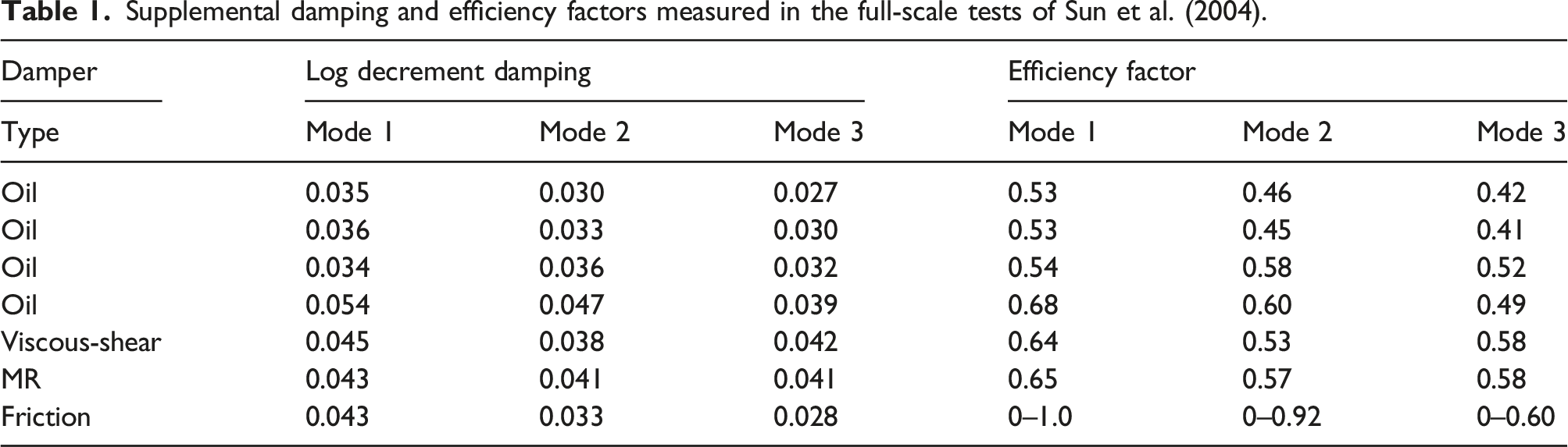
These experiments aimed at qualitative study or theory validation, while they are unable to determine the actual damping a real-scale damper can provide to a cable. Instead, the performance of a full-scale damper system that is of primary concern for practice needs to be evaluated on a full-scale cable. However, a real cable can only be set up in a cable fabrication shop due to its dimensions, rendering this kind of test costly and inconvenient. Few full-scale cable experiments have been conducted so far. Two cables around 220 m long were setup for damper performance investigation for vibration mitigation design of the Sutong bridge and the Stonecutter bridge (Sun et al., 2004; Zhou et al., 2016, 2018b), see Figure 7, wherein seven types of mechanical dampers, including oil dampers (both inner and external types) (Zhou and Sun 2007; Zhou et al., 2008a), friction dampers (Zhou et al., 2006a) and MR dampers (Zhou and Sun, 2013) were tested. It was shown that in most cases the measured additional damping from each damper was less than that predicted by the taut string-viscous damper theory. Corresponding efficiency factor (see Table 1), defined as the ratio of measured additional damping to theoretical estimation, varied in a broad range for different dampers (Sun and Huang, 2008; Sun et al., 2008; Zhou and Sun 2008b). Full-scale cable setup and photos of the damper installation (Sun et al., 2004). A–E: oil dampers; F: MR dampers; G–I: viscous-shear dampers; J: friction damper. Supplemental damping and efficiency factors measured in the full-scale tests of Sun et al. (2004).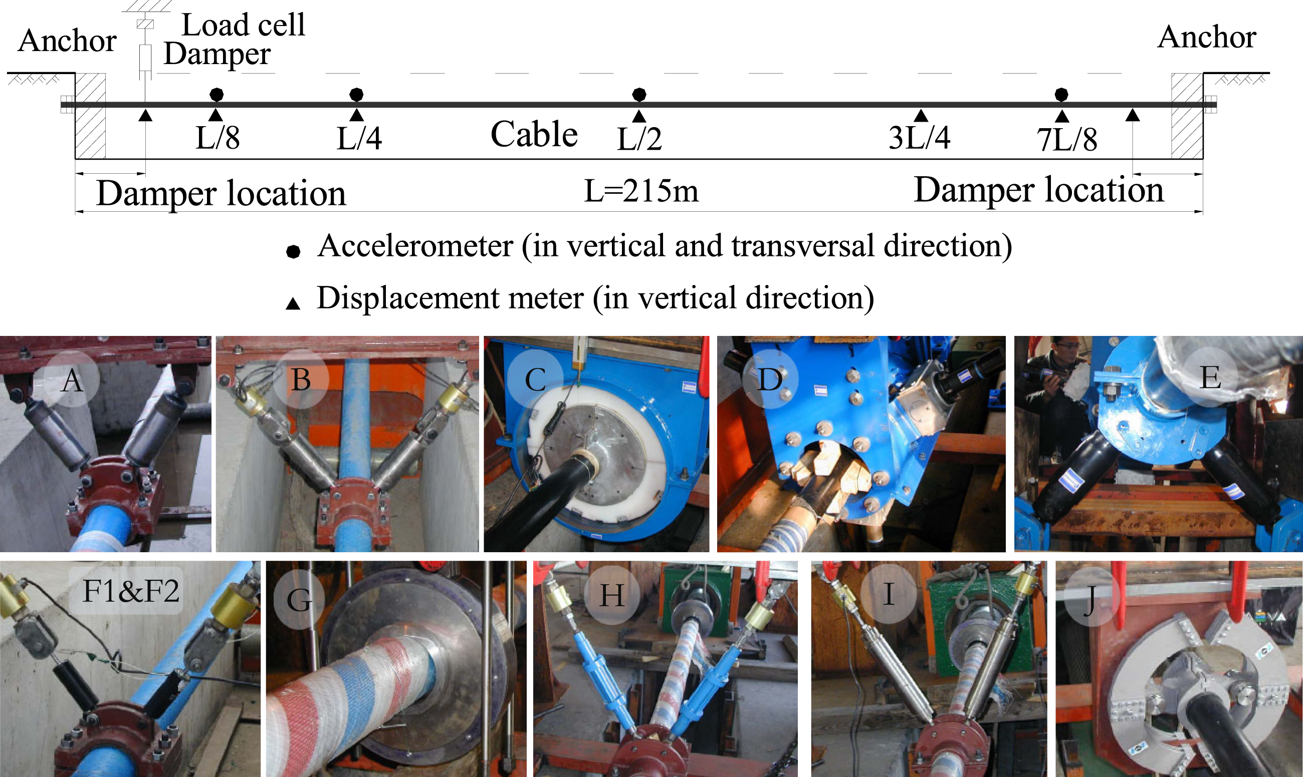
Performances of many types of cable dampers have been evaluated by field tests on the bridge, e.g., the viscous shear dampers (Chen et al., 2020a; Liu et al., 2000), oil dampers for cables on the Hangzhou Third Qiantang bridge (Chen et al., 2003a), MR dampers on Dongting Lake Bridge (He et al., 2002a, 2002b), and MR dampers on the Changsha Hongshan Bridge (Yu et al., 2007). It is found that the measured damping ratios are roughly consistent with the theoretical predictions when taking damper intrinsic stiffness and support flexibility into consideration for viscous shear dampers (Chen et al., 2020a, 2020b). However, for viscous dampers the differences between measured damping ratios and predicted values are still obvious (Chen et al., 2020b), which is probably attributed to the joint clearance induced loss of the damping effects.
Most of the experiments and field tests are concerned with free decay responses and hence supplemental damping ratios, while there are several experiments where model cables under control were placed in wind tunnel to investigate cable responses under wind loads. For examples, He et al. (2018) studied the effectiveness of elastic cross-tie in controlling wake-induced cable vibrations in wind tunnel, and Liu et al. (2019a) investigated pounding tuned mass dampers (TMDs) in mitigating VIVs of a cable. The widely implemented bridge health monitoring systems provide alternate ways such as field observations and tests to investigate cable-damper systems. For examples, Main et al. (2001) evaluated damper performances on the Fred Hartman Bridge, and Chen et al. (2003d) investigated MR dampers on the Dongting Lake Bridge. Recently, Wang et al. (2022a) monitored the performance of eddy current axial dampers on the Sutong Bridge.
Typical device/scheme
Viscous damper
Viscous dampers are the most widely used dampers for cable vibration control. The damper only allows deformation along the damper axis, and hence can provide damping in one direction. When both in-plane and out-of-plane vibrations are targeted, as least two dampers are usually attached at one location of the cable.
Even though viscous dampers are frequently modeled as a dashpot with one parameter–viscous coefficient. Experimental results show that the coefficient is frequency dependent, generally decreasing along with increasing vibration frequency (Chen et al., 2020b). Frequency dependency may be considered using the fractional viscous model (Krenk and Høgsberg, 2005; Sun and Chen, 2015).
The damper also exhibits nonlinear behaviors and the non-linearity is adjustable in damper design (Taylor and Constantinou, 1995). The power-law viscous damper model has been used in cable-damper system analyses. Main and Jones (2002b) derived universal curves for such dampers based on damping force equivalence in one cycle. Optimization of damper coefficient considering non-linearity can also be approximated based on dissipative energy equivalence (Hoang and Fujino, 2009). Viscous dampers have been used on many bridges (Fujino et al., 2012) including the Sutong Bridge in China (Chen et al., 2020b).
Viscous shear damper
Viscous shear damper is a typical viscoelastic damper, which can be modeled using the Kelvin model. The stiffness and damping coefficients depend on the amplitude and frequency of the dynamic deformation (Chen et al., 2020a). Such dampers have been widely used in Japan (Fujino et al., 2012; Yoneda and Maeda, 1989) and in China. Empirical models have been developed to relate the stiffness and damping coefficients to the viscosity of the viscous fluid, the shearing area and the thickness of the shearing layer (Liu and Liu, 2000; Yoneda and Maeda, 1989). Particularly, the stiffness coefficient increases exponentially while the damping coefficien decreases exponentially with respect to frequency (Chen et al., 2020a). The dampers have been used on the Xiazhang Bridge (Li and Du, 2012), the Shishou Changjiang Bridge (Liu et al., 2020a), and the Jiayu Changjiang Bridge (Zhao et al., 2021).
Friction damper
Friction dampers ideally can provide frequency-independent damping. There are already many applications, e.g., on the Sunningesund Bridge (Kovacs et al., 1999), the Uddevalla Bridge (Hjorth-Hansen et al., 2001), the Incheon Bridge, and the Third Wanzhou Changjiang Bridge (Zhou et al., 2022a). Coulomb friction model is widely used for damping analysis. Damping appreciated based on force or energy equivalence (Main and Jones, 2002b) shows the same maximal supplement damping to cables as the viscous damper, while the optimal friction force is independent of vibration mode but depends on vibration amplitude. However, time-history responses of a cable with a friction damper, obtained by numerical computation, show larger maximal damping as compared to a viscous damper (Wang and Sun, 2014; Wang et al., 2016; Weber et al., 2010). The increased vibration suppression performance might be attributed to the fact that the friction damper induces energy transfer to higher modes and then dissipates the energy more rapidly (Chen and Sun 2017a, 2017b; Weber et al., 2010). This mechanism has also be found in other nonlinear dampers for cable vibration control (Le Diouron et al., 2003a, 2003b). The friction damper is characterized by the stick-slip motion. When it is activated, i.e., the cable is under kinetic friction, cable vibration is damped rapidly; when the friction interface is sticked, the damping effect is quite small (Zhou et al., 2022a).
High damping rubber damper
High damping rubber (HDR) dampers are widely used as internal dampers/deviators for cables (Nakamura et al., 1998; Takano et al., 1997). They can be modeled using the linear hysteretic damping model, with a complex stiffness coefficient and a loss factor. The design formulas of a cable with an HDR damper was provided by Fujino and Hoang (2008) and Cu and Han (2015a), respectively. Owing to the relatively large intrinsic stiffness effects, corresponding to a small loss factor, the maximal damping provided by HDR dampers to a cable is relatively small. However, HDR dampers can effectively suppress high-frequency and small-amplitude cable vibrations (Sun et al., 2021b).
TMD
Stockbridge dampers that are widely used for vibration mitigation of overhead power lines have also been introduced for cable vibration control. This type of dampers can be modeled as a TMD for evaluating their damping effects on cables. The frequency and damping analysis method was probably first formulated by Cai et al. (2006) and Wu and Cai (2006), and validated through model cable tests (Cai et al., 2007). Experiments on a 36 m long cable with a Stockbridge damper have further validated the damping effect, while the damper is found to activate only when the cable vibration amplitude is larger than a certain value (Di et al., 2020b). The measured damping is roughly consistent with that estimated using a cable-TMD model. Numerical analysis also confirmed the performance of a TMD on a cable (Di and Li, 2015; Liang et al., 2017). TMD-like absorbers were used for vibration control of suspender cable vibrations (An et al., 2019). Cu et al. (2017) found that a TMD composed of a mass and a HDR damper still needs to be tuned to a specific cable mode leaving the other modes subjected to lower damping. Wu and Cai (2009) compared the performances of near-anchorage dampers and TMDs for cable vibration control.
Other dampers/schemes
Many novel schemes/dampers for cable vibration control have been developed in the last two decades. The schemes/dampers that have been studied yet widely implemented are discussed in this section.
Shape memory alloy (SMA) is known for its superelasticity and hence SMA dampers have been considered for cable vibration control. Using a nonlinear hysteretic model of the damper and a numerical model of the cable, Li et al. (2004a) showed the vibration mitigation effects and the influences of SMA damper parameters and location (Liu et al., 2007a). Mekki and Auricchio (2011) studied the influences of cross-section and length of the SMA damper on damping effect and it is found when the SMA damper is installed at the 10% of the cable length its performance could be better than an optimal TMD. Dieng et al. (2013) carried out a series of experiments on a model cable with a NiTi wire, showing that when the wire is installed far from the anchorage the damping performance is pretty good.
Hwang et al. (2009) proposed an isolation system where the cable-deck connection allows lateral sliding and an viscoelastic damper is used for energy dissipation, showing superior damping effects as compared to traditional systems of a cable with a transverse passive damper. Cables with passive viscoelastic dampers placed at the supports along the chord have also been investigated (Jiang and Li 2012; Jiang et al., 2010a, 2010b; Jiang et al., 2013).
Egger and Caracoglia (2015) proposed a multiple-mass-element pendulum impact damper for cable vibration mitigation which is realized by placing a strand inside a pipe bundled in the cable strands. The strand in the pipe would exert impact force on the cable during vibrations. Subsequent experimental studies have demonstrated the vibration mitigation effects (Egger and Caracoglia, 2015, 2022; Egger et al., 2016; Izzi et al., 2016).
Wang et al. (2022a) and Xiao et al. (2022) developed an eddy current axial damper and performed field tests on an existing bridge. The inertial mass and damping coefficient can be designed accordingly. Weiss et al. (2018) theoretically and experimentally studied a cable with a piece-wise linear absorber (elastic spring with a gap). Other novel dampers that have been proposed for cable vibration control include MR damper with permanent magnets (Yu et al., 2006), adjustable fluid dampers (Li et al., 2006; Xu and Zhou, 2007), rotational dampers (Impollonia et al., 2009), electromagnetic damper (Jung et al., 2017; Wang and Chen, 2014), pounding TMDs (Liu et al., 2019a), shunted flexible piezoelectric dampers (Xie et al., 2019), shear thickening fluid dampers (Lin et al., 2020), and particle dampers (Dan et al., 2021; Wang and Dan, 2022). While most lateral dampers are installed on the top of a support, dampers can also be placed on the bridge deck and connected to the cable using a rod which also plays a role in amplifying the damping and inertial force (Wang et al., 2007; Wang and Wang, 2013), similar as in the case of the Normandy bridge (Virlogeux, 2005).
On damper design
For damper design considering multiple cable modes, Wang and Chen (2002) and Wang et al. (2005a) proposed a method based on optimal control theory using a numerical model and assuming Gaussian white noise excitation. Weber et al. (2009) used the universal curves to determine the optimal damper coefficient according to the intersection of those corresponding to the lowest and highest modes of concern respectively. Note that the optimal damper sizes decided according to free vibration analysis and random vibration analysis are different while the impact on the variance of response is negligible (Sinha, 2016; Zhou et al., 2010). Apart from design according to damping, an energy based method for damper design was presented by Cheng et al. (2010). Influences of cable parameter variation in construction and uncertainty in cable and damper properties have been accounted in design (Dan et al., 2014; Mohammadi et al., 2017). Considering different wind excitation cases, Cárdenas et al. (2008) discussed the best damper location of cables on the cable-stayed bridges using a 3D model of the whole bridge.
For suppressing RWIVs, the required damping is about 0.5% (approximately 0.03 in logrithmic decrement damping), as recommended in several specifications (PTI DC45.1-18; fib Bulletin 89). The modes that need to achieve such a damping level nevertheless are still arguable. For short cables, the first 3 or 5 modes are normally concerned because the RWIVs are known to occur in the frequency range 0.6 Hz–3 Hz. However, for long cables with lower fundamental damping, e.g., 0.23 Hz for the longest cable of the Sutong Bridge, almost 14 modes have a frequency lower than 3 Hz. A damping ratio of 0.5% is difficult to achieve for all the modes. Yang et al. (2021a, 2022) proposed to exclude the first two modes of long cables in design and hence more higher modes can attain sufficient damping, as RWIVs are less possible to happen in a cable mode with frequency lower than 0.6 Hz. For mitigating cable VIVs, it is suggested to increase cable logrithmic decrement damping to 0.01 or 0.015 (Kumarasena et al., 2005; Yoneda, 1993). It is also challenging to supplement such amount of damping to high modes vulnerable to VIVs, while a criteria of lower damping requirement (corresponding Scruton number larger than 1.2) was recommended in Casas and Aparicio (2010). Indeed, for long cables, the number of modes targeted for vibration mitigation and the damping requirement for the respective mode are still not fully established.
Cable multimode vibration mitigation
As aforementioned, RWIVs occur in multiple cable modes, while most traditional passive dampers at one location can only be tuned to a particular mode and the other modes are subjected to sub-optimal control. Besides, damping effects are constrained by damper installation height and sag effects of long cables. It is noted that to supply sufficient damping to the longest cable (597 m) of the Third Bosphoros Bridge, the dampers are installed about 7.4 m high above the bridge deck (Guesdon et al., 2020). Such a large installation height poses difficulties in damper support design, damper inspection and maintenance. The aesthetic of the bridge is also affected. In this regard, it has been a hot topic to breakthrough those limits on cable damping. Different types of techniques have been resorted for this purpose.
Active control
Fujino et al. (1993) proposed to take advantage of the parametric vibration mechanism, by controlling the motion of one cable end to mitigate cable lateral vibrations, so-called acitve tension/stiffness control, and validated the control scheme by model tests. Fujino and Susumpow (1994) and Susumpow and Fujino (1995) further conducted experiments on a shallow cable and found that the active stiffness fails in particular cases. Achkire and Preumont (1996) investigated a similar scheme and proposed a control algorithm with cable tension feedback, which was validated through experiments and it was found that multimode vibrations achieved high-damping and the instability owing to parametric vibration was also avoided. Active stiffness method has also been used to control bridge girder vibrations, as experimentally studied by Warnitchai et al. (1993) using a model of a cable anchored at the end of a cantilever beam. The control scheme was further implemented with the aim to suppress both cable and bridge deck vibrations and the effects were demonstrated by a 30 m long model of a cable-stayed bridge during construction (Bossens and Preumont, 2001). Using the active stiffness control scheme and based on displacement and velocity measurements, Wang and Xu (2008) developed optimal control algorithm targeting RWIVs. Zhao and Zhu (2011) formulated a stochastic optimal control using axial cable support motion. Zhu and Li (2009) and Zhu (2010) considered bending stiffness of cables in active stiffness control, and compared the performances of different control algorithms, i.e., Linear Quadratic Regulator (LQR) and Bang-Bang, and found that the peak of control force of using the latter algorithm is smaller. Huang et al. (2018) developed a giant magnetostrictive actuator for active stiffness control and performed model tests.
The aforementioned studies apply control force in the direction of cable chord line, while Baicu et al. (1996) applied Lyapunov theory to ensure the stability of passive and active control by using cable support motions not along the chord line. Canbolat et al. (1998) proposed adaptive boundary control perpendicular to cable chord line and focused on out-of-plane vibrations. Faravelli et al. (2010, 2011) proposed SMA wires based active control method, and carried out model tests for validation. Zuo et al. (2008b) also investigated SMA dampers for active control (Zuo and Li, 2011; Zuo et al., 2009). Zhang et al. (2014a, 2014b) formulated optimal bounded semi-continuous control of nonlinear random vibration of cables.
Semi-active control
Semi-active dampers
MR damper and electrorheological (ER) damper have a similar structure as normal oil dampers, while properties of the viscous fluid are adjustable under applied magnetic or electronic fields. They are hence used as semi-active control devices. Relevant studies have focused on modeling MR/ER dampers, development of control algorithms, and experimental/field tests for validation. Novel types of devices based on MR/ER units and integrated systems have also been investigated.
The use of MR damper in civil engineering, including for cable vibration control, started around 2000s. The earliest focus was placed on the relation between damper properties and the input voltage. Several models were used to describe the relation, including the Bingham model, the Bounc-Wen model, and the viscoelastic model. Wang et al. (2002b) used the Bingham model of MR dampers, considering cable sag and bending stiffness, to compare damping effects under different input voltages. Furthermore, based on the Bouc-Wen model established by Spencer Jr. et al. (1997), Wang et al. (2002a) built a model of a cable with a MR damper, and numerically obtained the modal damping versus input voltage for the first three modes. Using the aforementioned results, the optimal input voltage for the first mode was derived (Wang et al., 2003c). Then the MR dampers were installed on the Dongting Lake Bridge. Field tests of cable damping under different voltages were found to agree with theoretical results. Chen et al. (2003d, 2004d) and Duan et al. (2002) implemented MR dampers on the 156 cables of the Dongting Lake Bridge. Field measurements confirmed that when the input voltage varies from 0 to 10 V, there is an optimal value to maximize the modal damping.
Wu et al. (2004b) considered MR damper as an equivalent viscoelastic damper and developed simulation and optimal design tools for practice (Wu et al., 2005), with application to the Third Qianjiang Bridge. The test results on a 154 m long cable showed that the damping effect of the MR damper with a constant input voltage could be better than a regular oil damper (Wu et al., 2004a). Hu et al. (2006) carried out MR damper experiments under various voltages, frequencies and amplitudes, and estimated the viscous coefficients in varied cases for design using the optimal design curves of a cable with a viscous damper. The design method has been validated on the Dongting Lake Bridge. Based on the cable-MR damper system on the Dongting Lake Bridge, Duan et al. (2005a) used a viscoelastic model in parallel with a friction element, considering damper support stiffness and the concentrated mass of damper movable components, and then derived a comprehensive formula for open-loop and closed-loop MR damper design (Duan et al., 2005b, 2005c, 2006; Duan et al., 2007, 2019; Ko et al., 2005; Zhang et al., 2019a). In the context of Sutong Bridge, Xu and Guo (2018) evaluated MR dampers for suppressing both in-plane and out-of-plane vibrations using the parallel viscous and friction damper model.
Control algorithms
With the MR/ER damper models, another issue to address is the adjustment of the voltage according to real-time cable vibrations, i.e., the control algorithm. Johnson et al. (2007, 2003, 2000) proposed the clipped LQR algorithm and showed advantages of semi-active control by comparing with passive damper and active control. It has shown that semi-active control can achieve 72% performance of active control. The semi-active damping was further validated experimentally (Christenson et al., 2006). A number of subsequent studies have also demonstrated the effectiveness of LQR and linear–quadratic–Gaussian (LQG) control algorithms and their variants. Chen et al. (2003b) proposed a discrete time based model for ER/MR damper voltage adjustment, and the method was found to perform better as compared to the clipped LQG algorithm. Furthermore, a bi-linear viscous damper model is used to emulate MR/ER damper behaviors (Zhou and Sun, 2010), and a 12 m long cable attached with an ER damper was used to validate the effectiveness of the proposed algorithm (Chen et al., 2004b). Chen (2004) derived optimal control force based on the LQR algorithm, and hence the voltage is adjusted according to the obtained force-displacement relation of the damper. A comparison of optimal passive damper, active MR damper, and passive MR damper was performed, suggesting better performance of semi-actively controlled MR damper. Using modal expansion method for cables and modeling MR damper as a viscous dashpot and a friction damper in parallel, Li et al. (2005, 2007a) and Liu et al. (2006) were able to obtain the optimal feedback gain and then equivalently set MR damper input based on the LQR algorithm. Numerical results thereof showed that the semi-active algorithm can better follow and realize active force. Liu et al. (2007b) proposed an algorithm based on acceleration feedback, using first- and second-order integration to determine the best control force, and used model tests for validation where the results confirmed that the algorithm could achieve better results than the passive-on and passive-off modes of MR dampers. Using a numerical model of the cable and the Bouc-Wen model of the MR damper, Wu et al. (2006b) evaluated influences of different damper parameters, and Wu et al. (2007a) compared different semi-active algorithms and showed that the variation of the voltage switch method has limited influences on the performance. A comparison of different control modes of MR dampers for cables can also be found in Jung et al. (2008).
Duan et al. (2004, 2005c) proposed collocated state-derivative feedback control based on the finite difference model, along with validation using the cable-MR damper system on the Dongting Lake Bridge. Wu et al. (2007b) and Wu et al. (2006a) proposed voltage adjusting method based on directions of measured displacement and velocity. Chen et al. (2017) also investigated the algorithm based on displacement and velocity directions. Ni et al. (2002) using a full-order cable-MR damper model with LQG control algorithm for numerical analyses, and then trained a neural network offline, which then can be used for voltage control in real time, see also Chen et al. (2001) and Wang et al. (2003a). A three-layer back propagation neural network has also been proposed by Chen et al. (2003c, 2004c).
Beside the aforementioned algorithms based on the classic active control algorithm, algorithms to emulate an optimal passive damper have also been developed and implemented in practice. Weber et al. (2008) and Weber and Boston (2010) proposed cycle energy control, where the MR damper was modeled as a viscous damper in parallel with a nonlinear viscous damper, the equivalent dissipation energy is computed. Boston et al. (2009) proposed an evolutionary algorithm for semi-active cable vibration control. Based on a viscous damping with negative stiffness model for MR dampers, Weber and Boston (2011) proposed a clipped algorithm and Weber and Distl (2015b) derived a LQR based semi-active algorithm for cable vibration control, with validation experiments performed on a 16.5 m long cable. Weber and Distl (2015a) tested the energy based algorithm on a 228 m long cable and experiments have also been conducted on the Eiland bridge, the Sutong Bridge, and the Russky bridge.
Experimental studies.
Using a 30 m long model cable, Maslanka (2007) compared performances of passive MR damper and semi-actively controlled MR damper which can achieve consistent damping for varied cable amplitude. It was found that because the limitation of the damper force, the experimental damping was less than the theoretical prediction. Huang et al. (2012) formulated the relation between input current and equivalent viscous coefficient of a MR damper from experimental results and then proposed optimal control strategy based on the passive optimal viscous coefficient. The effectiveness of the algorithm has been experimentally validated on a 95 m long cable. Further to consider the non-linearity of the MR damper, Huang et al. (2015, 2019a) and Liu et al. (2013a, 2016) proposed a bi-linear relation between viscous coefficient and input current of MR damper built from experimental results for semi-active control according to the optimal viscous coefficient.
Recent developments and applications.
Semi-active control of cable vibrations is still a topical area. Yu et al. (2011) proposed displacement feedback based Bang-Bang control algorithm; Wang and Sun (2013) and Wang et al. (2015b) proposed to adjust the MR damper voltage emulating optimal friction force. Zhou et al. (2006b) used the Dahl model to model MR dampers, and developed a semi-active method based on displacement and velocity feedback, illustrating the control effect of the MR damper on support-excited vibrations (Zhou et al., 2008b). Jeong et al. (2019) built a semi-active control system using Arduino framework and MR dampers with acceleration feedback and embedded LQG algorithm. Novel MR dampers or combined systems have also been developed for cable vibration control, e.g., Li et al. (2006) and Zhao et al. (2019). Casciati and Ubertini (2008) included MR damper into a TMD for cable vibration control, and nonlinear vibrations were considered. Wu and Cai (2010) built a control-oriented model and used numerical and experimental methods to validate the effectiveness in a semi-active cable-MR damper system. Zhou et al. (2020b) considered non-linearity and time-varying stiffness of cables for cable-MR damper systems. Other studies on cable-MR damper systems include the locking force analysis (Liu et al., 2008), combination of passive negative stiffness along with semi-actively control MR dampers to emulate active control (Shi et al., 2022), and optimal input energy analysis (Chen et al., 2006), extension of the LQG algorithms to frequency domain (Chen and Chen, 2017; Chen and Ni, 2017). He et al. (2007) analyzed the stability of a cable with semi-active control under parametric excitation. Huang and Sun (2022) proposed an optimal control algorithm for a cable-MR damper system using the pole assignment theory. Semi-active control using MR dampers has been applied to mitigate parametric vibrations of cables (Chen and Ying, 2005; Ying et al., 2007; Zhou et al., 2007). Apart from the aforementioned dampers, SMAs have been considered for semi-active control of cable vibrations, including parametric vibrations (Li et al., 2004b) and RWIVs (Zhou and Sun, 2008a).
MR dampers under semi-active control have been applied in several cable-stayed bridges, including for the long cables of the Sutong Bridge (replaced in 2019 during cable vibration mitigation system upgrade) and the Russky bridge (Weber and Distl, 2015a). However, most of the aforementioned semi-active control methods/algorithms have not been applied in practice.
Integrated/intelligent systems
Semi-active control require power supply and probably cable response measurements. Therefore, it is highly desirable to integrate the functionality of vibration sensing, vibration control, and energy harvesting, eventually leading to an intelligent system. Kim et al. (2009, 2011) proposed to integrate MR damper with electromagnetic interference (EMI) device, where the EMI device generates electricity from cable vibrations as the power source of the MR damper. They used a cable of 44.7 m long for experiments where the MR damper and EMI device were installed at different locations, and showed such a system performs better in vibration control as compared to using MR damper with constant voltage. They also showed that the EMI device with closed-circuit provides damping force on the cable (Kim et al., 2010). Furthermore, Jung et al. (2011) added vibration measurements and energy storage functions in the proposed system. Note that Chen et al. (2016b) developed a self-sensing system together with MR damper by incorporating displacement and acceleration measurements, leading to a so-called self-sensing cable vibration control system, and tested on a model cable. Wang et al. (2017, 2018, 2019d) developed power supply system using rotary electricity generator for MR dampers in cable vibration control, and a drive chain was used to transform the cable transverse vibrations to rotations of the generator. Experiments on a model cable of 21.6 m long have demonstrated the negative stiffness and viscous damping effects of the combined system. Both cases when the MR damper and the generator close to the same cable end and respectively close to two cable ends were tested.
Distinguished from the previous studies using separate components for energy harvesting and vibration control, Shen and Zhu (2015) further explored electromagnetic (EM) dampers for both energy harvesting and vibration control. Shen et al. (2016) validated the damper performance on a 5.85 m long model cable. Jamshidi et al. (2017) proposed methods to control the energy harvesting and vibration mitigation using EM dampers for a cable, where the damper operates in the way that energy is harvested when the damper is passive and the passive/semi-active modes can be switched. By numerical simulations of the circuit and the damper mechanics, vibration control performances under different modes have been demonstrated. Kye et al. (2019) further proposed an integrated solution including energy harvesting, monitoring and vibration control using EM dampers.
Negative stiffness devices and inerters
Semi-active/active control has excellent performance in multimode vibration mitigation of cables while requires power supplies. The durability and stability of those supporting systems are still challenging as bridges are often located in harsh environments (Wang et al., 2019b; Wu et al., 2020; Zhou et al., 2021a). Inspired by the negative stiffness effect observed in control force-displacement curves of semi-active/active control applications, particularly on cables (Li et al., 2008b; Ou and Li, 2010; Xu et al., 2022b), passive means to realize negative stiffness has been pursued. A pre-compressed spring can assist the movement away from the equilibrium point in the direction perpendicular to the axis of the spring, and such negative stiffness behaviors have been validated experimentally (Sarlis et al., 2012; Pasala et al., 2013). Chen et al. (2015) thus proposed a combination of a viscous damper with such a negative stiffness device (NSD), passively increasing the achievable cable damping largely. Zhou and Li (2016) performed model tests of such a system and validated the damping improvement. Negative stiffness can also be realized by an array of magnets for enhancing cable damper performance (Shi et al., 2016, 2017a, 2017b). Those devices have non-linearity while its effect can be controlled in the design (Chen et al., 2015; Shi and Zhu, 2018b). A prototype of negative stiffness device and the experimentally measured force-displacement relation.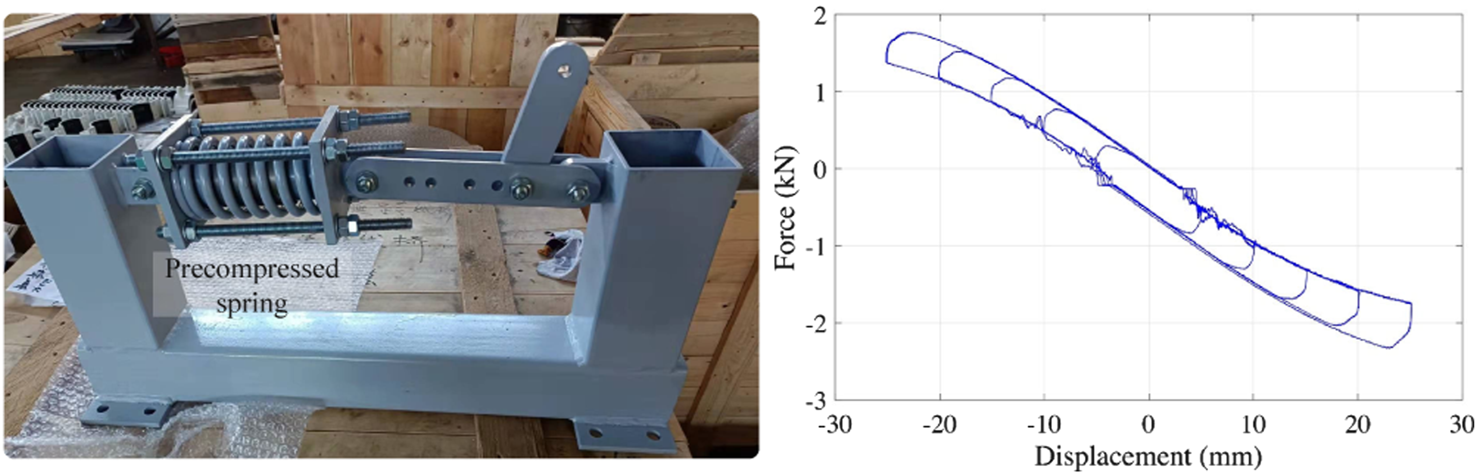
The earlier studies used a model of an NSD and a viscous damper in parallel attached to a cable. Optimal design of NSDs and dampers for multimode vibrations have been considered by Javanbakht et al. (2018) and Javanbakht et al. (2020b). When considering damper support flexibility, the effects of springs with positive and negative stiffness in series were discussed in cable vibration control (Dong and Cheng, 2021; Javanbakht et al., 2020a; Zhang et al., 2019b; Zhou et al., 2020a, 2021b). Performance of cable dampers with linear hysteretic damping, e.g., HDR dampers, can also be improved using the NSD by reducing their inherent stiffness (Sun et al., 2022c). In the case of damping system upgrade/maintenance, the NSD can be placed at a different position instead of at the external damper position (Gao et al., 2022c; Sun et al., 2022c), but tends to be more effective when close to the damper. Figure 8 shows a prototype NSD using a precompressed spring along with a lever beam for force amplification (Pasala et al., 2013; Sun et al., 2021a; Wang et al., 2020b) and the experimentally obtained force-displacement is also shown in the figure. Accordingly, a negative stiffness coefficient −300 kN/s can be achieved which fulfills the practical use of NSDs for enhancing damping of long cables (Sun et al., 2022c).
Negative stiffness can be equivalently realized by inertial mass, as inertial force is always in the opposite direction of the restoring force. The difference is in that the negative stiffness achieved by inertial effect is frequency-dependent. Beneficial effect of attached mass along with damper installation on a cable has been discussed theoretically (Duan et al., 2005b; Krenk and Høgsberg, 2005; Zhou et al., 2018a). Generally, the added mass is small enough to be ignored when a regular damper is installed. Recently, as the inerter that amplifies inertial force generated by physical mass, through gearbox or leverage (Figure 9), is gaining popularity in structural control, it has been extensively studied for cable vibration control since Lazar et al. (2015, 2016) first considered a cable attached with a tuned inerter damper (TID), i.e., an inerter in series with a Kelvin damper. Sun et al. (2017) provided a parameter optimization method for two cables interconnected with a TID and a cable with a TID, and compared damping performance of different configurations. The damping enhancement effect of an inerter in parallel with a viscous damper (called inertial damper) on a cable was shown by Lu et al. (2017), Shi and Zhu (2018a) and Cu et al. (2018), respectively using numerical and analytical formulations, and subsequently validated by Lu et al. (2019) via hybrid testing on a prototype inertial damper. Performance of cables with TID under seismic loading has also been examined (Radu et al., 2020). A schematic plot of an inerter device and its mathematical model (Sun et al., 2017).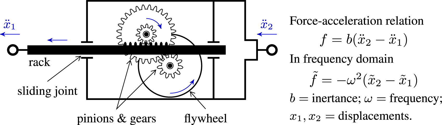
A prototype inertial mass damper was designed by combining electromagnetic damping and fly wheels, which was attached to a model cable, validating the improved damping effect (Wang et al., 2019c, 2019h). Full-scale experiments on a 135 m long cable further validated the performance of inertial mass dampers (Li et al., 2019c, 2020; Shen et al., 2021). Explicit approximate expressions or design methods have been provided for designing inertial mass dampers on a cable for a broad range of inertance (Li et al., 2022b), with cable sag (Di et al., 2021c; Wang et al., 2019g, 2020c) and bending rigidity (Gao et al., 2021c; Wang et al., 2019f) taken into account.
For multimode damping improvement, various layouts of combining inerters, springs and dashpots for a cable were examined and the beneficial configurations have been identified (Luo et al., 2016, 2017, 2018, 2019). Chen et al. (2021a) compared NSDs and inerters for multimode cable damping enhancement when combined with viscous dampers and springs. It is shown that when more modes are considered, it is difficult to balance the damping enhancement of lower and higher modes, as inerter provides frequency-dependent force (Figure 9) while the NSD can equally improve multimode damping. For inerter-based absorbers, TIDs outperform inertial mass dampers in terms of multimode damping performance, as also found by Huang et al. (2019b), Gao and Wang (2020), and Shi et al. (2021). As viscous-shear dampers and HDR dampers are also widely used in practice (Fujino and Hoang, 2008; Nakamura et al., 1998), and they can be modeled well using the linear hysteretic damping model, performance of such dampers when combined with the inerter has been examined (Sun et al., 2021c). It was showed that superior performance can be achieved when an inerter in parallel with a damper is arranged with another inerter in series. A combination of the NSD and the inerter could further improve their respective performance in multimode cable damping enhancement (Gao et al., 2022b). Beside the damping effect, Xu et al. (2022a) analyzed the VIV responses of a cable with an inerter-based absorbers and compared the performances of different layouts.
There have been other ways to increase inertial effect at the cable damper location to enhance damper performance. Wang et al. (2015a) developed a lever-type damper to amplify the damping force and the inertial force meantime. For dampers with rotating components, e.g., electromagnetic dampers and eddy current dampers, it is straightforward to add fly wheels to adjust inertance (Li et al., 2019c; Wang et al., 2019f, 2021). Liu et al. (2021b) integrated gears and fly wheels in the widely used viscous-shear dampers and the assembly was attached to a model cable for tests (Liu and Liang, 2021; Liu et al., 2021a).
Dampers distributed at different locations
For a long cable, apart from the external damper, there are often other attachments in the cable guide pipes, e.g., bushings, for waterproof and for reducing the bending stress of the cable near its end (Takano et al., 1997). The effect of those components on the damping effect of an external damper is of practical interest (Main and Jones, 2003; Takano et al., 1997; Yoneda et al., 1995). Generally speaking, the bushing modeled as a spring has negative effects on the damping can be provided by an external damper because it equivalently reduces the installation distance of the external damper or increases the inherent stiffness of the external damper. Di et al. (2020a) further refined the interaction effects between an external damper and an attachment in cable guide pipe by modeling the attachment as an HDR damper and taking cable sag into account. Field tests thereof validated their interaction effects.
As cable length increases, the damper installation distance from a cable anchorage becomes relatively smaller as compared to the cable length. A damping system composed of two or more devices distributed at different locations of a cable is revisited for the purpose of increasing damping. Figure 10 shows feasible positions for the installation of damping devices. However, when two viscous dampers are close to one cable end, the maximal damping for a lower mode can not be increased as compared to a cable with only the damper farther from the nearest cable end (Caracoglia and Jones, 2007a; Hoang and Fujino, 2008). A feasible way to increase the maximal damping is the installation of viscous dampers near two respective cable ends, when the damping is linearly superposable. Similar conclusions can be drawn when different types of linear dampers are installed at different locations (Cu et al., 2015; Wang et al., 2019e, 2022b), without or with cable sag taken into account (Sun et al., 2019b, 2022a). In contrast, a TMD when combined with a viscous damper can considerably improve the damping for a particular mode (Cu and Han, 2015b) and their interaction is negligible. For a cable with considerable bending stiffness, rotational dampers can be combined with lateral dampers for damping enhancement with them installed at the same location or different locations (Chen et al., 2016a; Impollonia et al., 2009). Wang et al. (2022c) further proposed to install two inertial dampers on a cable for damping enhancement. Feasible installation of multiple dampers distributed on a cable.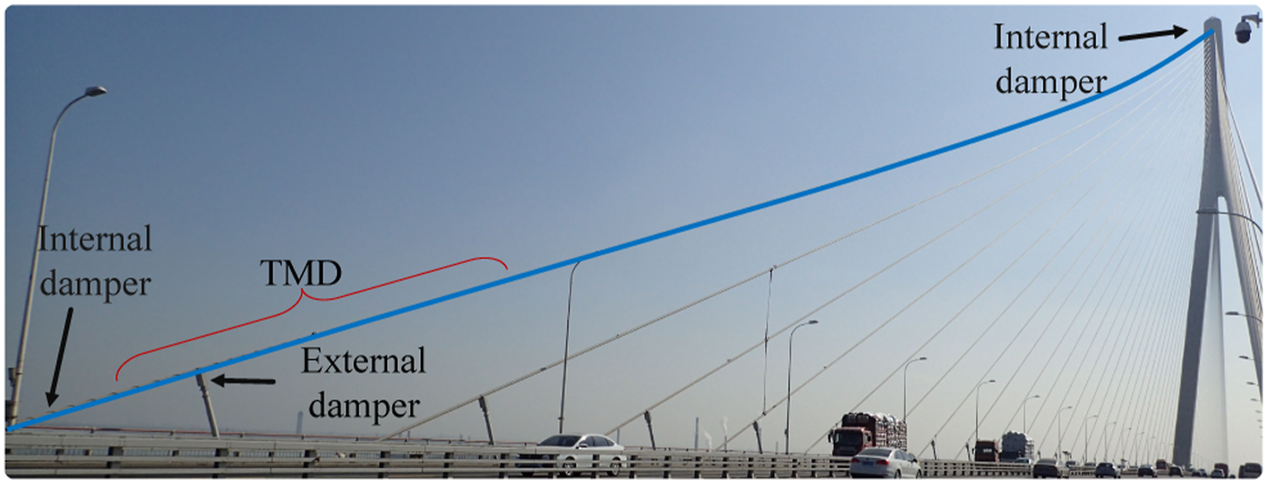
These previous studies are concerned with the combined damping that can be attained for lower modes of the cable, generally the first 5 modes. Recently, high-mode cable VIVs have been observed in long cables attached with an external damper. This corresponds to the case when the external damper is close to a node of the cable mode shape and hence the damping provided by the external damper is almost zero. The mode order is normally higher than 30, which has not been considered in traditional cable damper design. Therefore, different from the previous studies, Di et al. (2021d) focused on the combined effects of two dampers installed at different locations, to cover modes subjected to RWIVs and VIVs. Two common types of external dampers are considered, i.e., viscous damper and viscous shear damper (Di et al., 2021d; Sun et al., 2021b). Meanwhile, three types of devices have been considered for suppressing high-mode cable VIVs. The first one is also a viscous damper as it is widely used in practice (Figure 6). The other two include an HDR damper and a TMD because they have been used for mitigating VIVs of suspenders or short stay cables (Argentini et al., 2016; Di et al., 2020b). Multimode damping effects of the three combinations of dampers on a cable were investigated by using complex modal analysis. Two viscous dampers have also been studied by Yang et al. (2021b) for covering a wide frequency band. It was shown that an additional viscous damper can directly supplement damping to the high mode prone to VIVs with relatively small negative effects on lower mode damping. The HDR damper improves the high-mode damping by modifying the cable mode shape such that the viscous damper is farther from the node of the corresponding mode shape while has relatively larger negative effects on lower mode damping. The TMD absorbs high-mode cable vibration energy while has nearly no effect on the damper targeting lower cable modes. The combination of an external damper and an HDR damper in the guide pipe has been implemented on the Sutong Bridge, as shown in Figure 11, and the high-mode cable vibrations have been successfully suppressed according to field monitoring (Sun et al., 2021b). Distributed damper system for multimode vibration mitigation applied to the Sutong Bridge.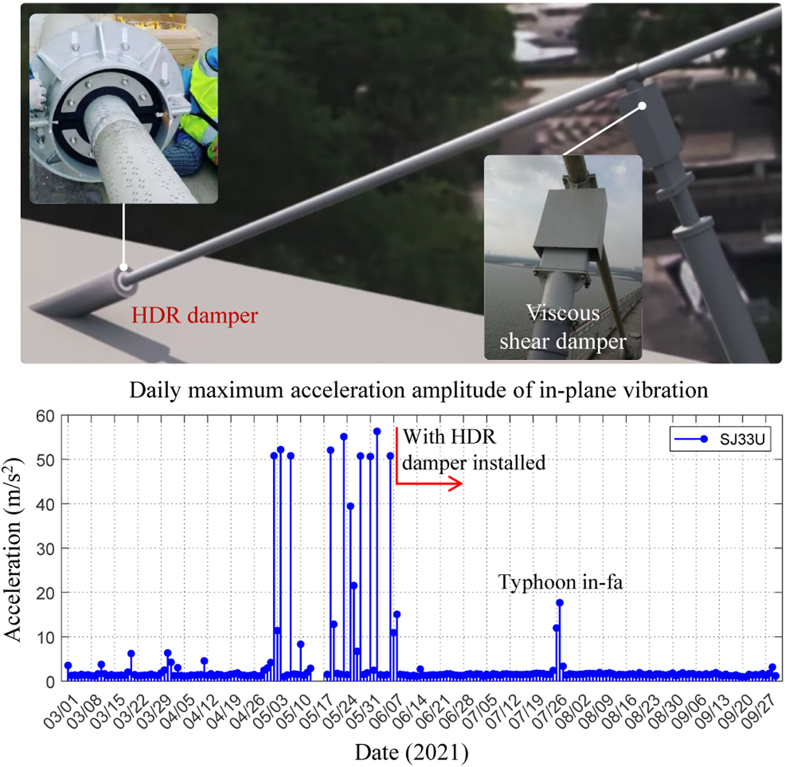
Cross-ties
Interconnections between neighboring stay cables were proposed to increase cable in-plane stiffness probably first in 1990s (Ehsan and Scanlan, 1989). The connections are named as cross-ties and the interconnected cables form a cable network. At the beginning, effects of cross-ties on redistribution of vibration energy of the connected cables were concerned; subsequently, their damping effects were paid attention to (Yamaguchi and Jayawardena, 1992; Yamaguchi and Nagahawatta, 1995). Flexible and dissipative cross-ties were found able to improve system damping. Furthermore, experimental studies on cables with secondary cross-ties showed that the nonlinearity effect plays an important role in main cable dynamic responses (Yamaguchi et al., 2001). Yamaguchi and Alauddin (2003) further investigated the interaction between main cables and secondary cables. Wei and Yang (2000) studied the in-plane and out-of-plane vibrations of multiple cables with cross-ties, and considered cable tension and frequencies under influences of horizontally aligned cross-ties and cross-ties respectively perpendicular to cable chords. The damping and dynamic responses were discussed and it was found that cross-ties perpendicular to cable chords perform better. Those early studies mainly used finite element models for numerical analyses or scaled models for experiments, where dynamics of the secondary cables was included.
To address cable vibration problems of the Normandy bridge, a combination of the near-anchorage dampers and cross-ties (so-called hybrid system) has been applied (Virlogeux, 2005). In the design of the Sutong Bridge–the first cable-stay bridge with a main-span over 1000 m in the world, as an alternate solution for vibration control of cables up to 577 m, Sun et al. (2005, 2010) investigated damping effects of hybrid cable networks (Figure 12). Based on the Fred Hartman Bridge in Houston, Caracoglia and Jones (2003) systematically studied the combined vibration mitigation effects of hybrid systems (Zuo and Jones, 2005). To further increase damping capacity of cross-ties, He et al. (2010) proposed to use viscoelastic connections between main cables and cross-ties, leading to damped cross-ties. HDR dampers can be designed as the joints between a cross-tie and a main cable (Figure 12), and experimental studies have shown their damping effect. It is noted that Nakamura et al. (1998) considered HDR dampers as spacers between twin cables. Other types of cross-ties have also been investigated, e.g., TMDs as a cross-tie to connect two cables, cross-ties integrated with inerters (Sun et al., 2017) and negative stiffness elements (Zhou et al., 2019c), and uniformly distributed elastic cross-ties (Jing et al., 2018). A typical hybrid system of cables with cross-ties and near-anchorage dampers.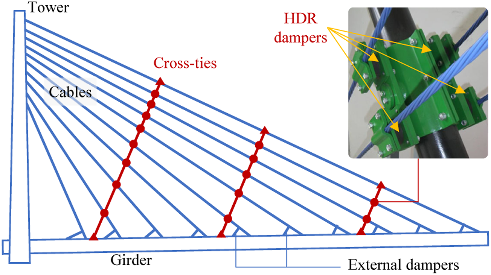
The studies using FEMs or experiments provide qualitative understanding of cables with cross-ties/dampers, but have difficulties in optimizing system configurations and parameters. In this regard, the complex modal analysis method in studying a single cable with dampers has been extended to study cable networks (Caracoglia and Jones, 2005a, 2005b, 2005c). The main cables are modeled as taut strings while the secondary cables are considered as massless spring/dashpot elements. The system frequency equation can then be formulated by using complex mode shapes or the dynamic stiffness method, which is a complex transcendental equation needs to be solved using a numerical method. On this basis, Caracoglia and Jones (2004) pursued optimized configurations of the cross-ties and further detailed their influences on damping (Caracoglia and Zuo, 2009). In the same framework, Ahmad et al. (2018b) established a generalized procedure to formulate frequency equation of complicated cable networks.
Dynamic analysis of cable networks using the analytical formulations gained popularity in the subsequent studies. Different configurations and parameters have been accounted. Ahmad and Cheng (2013b) and Ahmad and Cheng (2015) concerned the stiffness enhancement, frequency and mode shapes of multiple cables interconnected by one rigid cross-ties, and discussed the influences of length ratio, cross-tie location, the frequency ratio, mass-tension ratio, and the number of main cables. Effects of the stiffness and the number of cross-ties have been further investigated focusing on the formation of local or global modes (Ahmad and Cheng 2013a; Ahmad et al., 2015, 2016). Generally, to suppress localized oscillations, it is preferred to have evenly distributed softer cross-ties and to increase the number of cross-ties. Besides, Zhou et al. (2019a) investigated two cables with one cross-tie extended to ground.
For hybrid systems of cables with both cross-ties and dampers, the focus has been placed on both frequency enhancement and damping variation with respect to the configurations and parameters of the cable system. Zhou et al. (2014) characterized the complex frequency evolution with respect to spring and damper coefficients of a cable with a spring and a viscous damper respectively at arbitrary locations. Li et al. (2022a) found that larger damping can be achieved by replacing the viscous damper using a viscous mass damper. Ahmad et al. (2014) considered viscous-type structural damping of the cables and studied the effect of flexible cross-ties on multiple modal damping distribution of the system. Zhou et al. (2015) and Ahmad et al. (2018a) investigated two cables interconnected by a spring and with dampers attached to the cable near its anchorage. Zhou et al. (2019b) obtained frequency and damping evolution of a two-cable network interconnected with a damper along with variations in damper coefficient and location, and proposed a design method targeting multimode damping. It is difficult to draw general conclusions on the frequency and damping characteristics even for those relatively simple systems.
Most previous studies had modeled main cables as taut strings. Considering cross-ties are mainly desirable for long cables, Sun et al. (2019a) evaluated the role of sag effect in the systems dynamics. In recent studies, Di et al. (2021b) and Di et al. (2021a) found that when interconnecting cables with considerable sag using pretensioned cross-ties, the system frequencies in some modes could be decreased. The cable sag and bending stiffness effects on cable networks have been evaluated based on relatively simple systems (Younespour and Cheng, 2021, 2022a, 2022b). Note that Zhang et al. (2022) studied two cables with one rigid cross-tie in the context of suspender vibration mitigation taking into account the main cable bending stiffness. While most of the studies considered linear viscoelastic cross-ties, nonlinearity is in presence as the cross-ties can be loose in cable vibrations. In a series of studies, Giaccu and Caracoglia (2012, 2013), Giaccu et al. (2014a, 2014b, 2015), and Caracoglia et al. (2017) discussed variations of system frequencies and damping under the influences of cross-tie nonlinearity by using equivalent linearization method. Giaccu et al. (2017) further studied higher-order statistical moments of eigenvalue distributions of complex cable networks with nonlinear cross-ties.
For complex networks composed of several cables and multiple cross-ties, the analysis using complex mode shapes losses its advantages. The derivation of the frequency equation could be intractable and solving multimode frequencies from the equation without missing solutions is also challenging. Therefore, Chen et al. (2021b) established a generalized and dimensionless numerical model based on modal expansion and quasi-static correction, which can be used for both frequency/damping analyses and dynamic response computation, as shown in Figure 13, as an extension of the numerical model for a single cable with a damper (Johnson et al., 2003). The method has been combined with the genetic algorithm for design optimization (Di et al., 2022), which has been applied to a 8-cable system of the Sutong Bridge. Through such optimization, it was shown that localized modes with low damping can be avoided (Di et al., 2022). It is noted that the proposed method can be directly used to deal with suspender cables interconnected with spacers and dampers for design optimization. Generalized and dimensionless model with reduced number of degrees-of-freedoms for cable networks.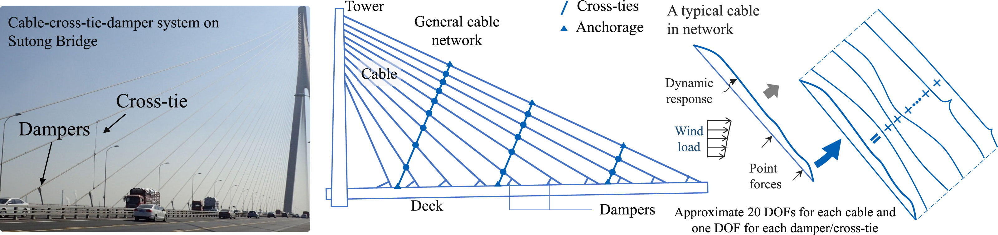
Experimental studies on cross-ties have been carried out mainly on model cables. He et al. (2018) validated the damping effect of damped cross-ties based on dynamic tests of three interconnected model cables. Zhou et al. (2017) and Yang et al. (2021c) used SMA wires as the cross-ties in experiments. Cable ross-ties have been installed on several bridges, e.g., the Normandy Bridge (Virlogeux, 2005), the Fred Hartman Bridge (Caracoglia and Jones, 2007b), and the Sutong Bridge for performance investigation (Figure 13). Experiments on large-scale cable-networks are still in lack for validating the theoretical findings.
Summary and outlook
A review of cable vibration and control is provided in this paper, with the focus on cable damping and damping supplementing method. Particularly, theoretical and experimental studies on cable-damper systems are comprehensively introduced. Present advances in supplement damping to cable multimode vibrations are discussed. Accordingly, the following future research topics are envisioned. • The number of vibration modes, or the frequency range of concerned vibrations (including both in-plane and out-of-plane vibration modes), needs to be further clarified in cable vibration mitigation. This is of significant importance in cable damper design. It is still quite challenging to balance the supplemental damping to cable multimode vibrations. • Guidelines for the design of cable vibration control are needed with the consideration of the recent observed problematic vibrations, particularly for long cables. • A number of novel concepts and devices have been developed in the last years. Field tests and long-term performance examination of these techniques are still needed. With added components/mechanisms, the damping system becomes more complicated, and the design details need to be further checked. • The damped cross-ties and hybrid solutions of cross-ties and dampers, as promising and competitive solutions for vibration mitigation of long cables, need experimental validation and field measurements to fully understand their performances. • Intelligent damping system for cables is of more interest in future, to provide a comprehensive solution to both vibration control and structural evaluation.
Footnotes
Declaration of Conflicting Interests
The author(s) declared no potential conflicts of interest with respect to the research, authorship, and/or publication of this article.
Funding
The author(s) disclosed receipt of the following financial support for the research, authorship, and/or publication of this article: This work was partly supported by the National Natural Science Foundation of China (Grant Nos. 52278314 and 51978506) and the National High-tech R&D Program (863 Program) of China (Grant no. 2006AA11Z120) which are gratefully acknowledged.