
Abstract
Circularly symmetric-shaped spot welds are desirable for welding applications as they relate to heat and fluid flow conditions in the melt pool with predictable weld penetrations and repeatable results. Non-circular spot welds on the other hand result in undesirable and unpredictable weld penetrations or non-bridging of the liquid melt pool across the joint. Two known causes for non-circular melt pools occur when welding dissimilar metals, or when welding with skewed electron or laser beams that are not perpendicular to the surface. A largely unexplored additional factor, shown here, is an asymmetric power density distribution within the beam that can create non-circular melt pools even though the beam dimensions are much smaller than the melt pool itself.
Keywords
Introduction
Electron and laser beam spot welds are often used for tacking parts together before being welded to minimise part distortion, 1 to join thin materials, 2 and/or to join temperature-sensitive components where heat input must be limited. 3 When used for tacking prior to making a continuous weld seam, the tacks are smaller than the final weld so as to be consumed by it but need to bridge across the seam to join materials on either side and hold them in place. For pulsed welds made with overlapping spots, it is also desirable to have circularly symmetric melt pools for precision and uniform weld appearance, and to properly join both sides of the weld seam. This is particularly important for thin materials where penetration control is essential.
Spot welds are typically assumed to be symmetric and circular as heat flows radially outward from the centre of the weld, while the penetration and weld size is controlled by the power density distribution of the heat source and duration.4–6 Material chemistry becomes an important additional factor since the melt pool shape in stainless steels (SSs) for example can be influenced by surface active elements such as sulphur that can reverse or alter the fluid flow convection that affect weld pool shape and penetration. This effect, known as Marangoni convection, is well studied for arc welds that form under conduction-mode heat flow conditions.7–9 It is also known to occur in electron and laser beam welds at low power densities where conduction-mode fluid flow conditions exist,5,10,11 but would not in itself predict non-circular spot weld geometries for beams with circularly symmetric power density distributions.
In this study, we examine a largely unexplored behaviour where an asymmetric, non-circular, spot weld shape develops in a transient keyhole melt pool in 304L SS. This behaviour is different than some other common situations where the spot welds may be non-circular and produce elongated or non-symmetric melt pool shapes for known reasons. For example, if two different SSs are welded together with different sulphur contents, the weld pool may shift towards the low sulphur content side, 7 creating an elliptical top surface shape. 12 Another condition is when the beam is positioned at an angle to the surface, where the beam's power density distribution skews, creating conditions that lead to elongated melt pools and non-symmetric penetrations that bulge in the direction of beam skewing. 13
A novel finding of this work shows that non-circular spot weld shapes can occur even when the beam is perpendicular to a single composition melt pool. This condition is one where the power density distribution of the heat source is asymmetric creating localised thermal gradients that drive thermal fluid flow in a way that elongates the weld pool shape more in one direction than in the other even though the size of the electron beam is small compared to the final melt pool.
Experimental procedures
The electron beam welder used in this study is a Hamilton Standard SN 605 with an R-40 gun, fitted with at W-Re ribbon cathode (CL-167-R) having a rectangular emitting surface measuring approximately 1 × 1.3 mm. The cathode was assembled in the electron gun per the Hamilton Standard procedures and alignment tools 14 and visually verified for proper centring. This older electron beam welder does not have a quadrupole magnet for stigmation and tends to produce non-circular overfocused beams. 15 Spot welds were made at 100 kV and 6 mA, on a 316 SS plate that was located at a work distance 127 mm below the top of the weld vacuum chamber, which corresponds to a lens-to-work distance LWD = 292 mm. All the welds were made in vacuum at 7 × 10⁻⁵ Torr, with the electron beam perpendicular to the plate, for both sharp focused and overfocused beams.
The 316 SS plate used in the experiments measured 100 mm wide and 75 mm long and was large enough for all the spot welds. The chemical composition of the plate was measured by a combination of optical emission spectroscopy, X-ray fluorescence, and LECO analysis for O, N, C, and S, and was shown to meet the UNS S31600 specification for all elements. The full chemical analysis is presented is supplemental Table S-1, which includes four measurements of the sulphur content that was determined to be 0.0095+−0.0006 wt%. The Creq. to Nieq. ratio for this alloy was calculated to be 1.56 based on the Suutala relationship, 16 indicating that this alloy would likely solidify with ferrite as the primary phase for slower cooling rate arc welds, but may solidify as primary austenite for more rapid cooling conditions 17 such as the transient short-duration EB spot welds made here. The starting plate was non-ferromagnetic and was shown to contain 0% ferrite as measured by the Magne-Gage technique.
Short-duration spot welds were made by ramping the beam up to full power over a 1 s interval and holding the beam power for an additional 0.5 s before turning the beam off, equating to 600 J of energy for each spot weld. Videos of the melt pool formation were taken through the EB viewing optics at 240 frames per second rates to watch the weld pool boundary develop. These videos are available as supplemental information and show that the sharp focused beam generates a small circular weld pool that maintains its shape as it grows, whereas an overfocused beam generates an elliptical-shaped weld pool that maintains its non-circular shape that grows with time as will be discussed in more detail later.
The power density distribution within the electron beam was measured with the Enhanced Modified Faraday Cup (EMFC) diagnostic.18,19 The diagnostic operates by deflecting the beam at the full weld power over a radially oriented slit disk in a circular pattern to create profiles of the beam at different angles. The individual beam profiles are then reconstructed using a computed tomographic method (CT) to analyse the beam's power density distribution as detailed previously.15,20 The data acquisition system captured data at 500k samples/s to provide high-resolution CT-reconstructed profiles of the beam as it circled at 85 Hz over the slit disk. The orientation of the EMFC diagnostic, as it faces the operator, provides the orientation of the beam relative to the x- and y-orthogonal axes of the electron beam welder with the same view as the operator sees through the EB viewing optics within approximately ±1 degree angle of rotation. The coordinate system used in this study is designated with the x-axis moving left to right as the operator faces the welding table.
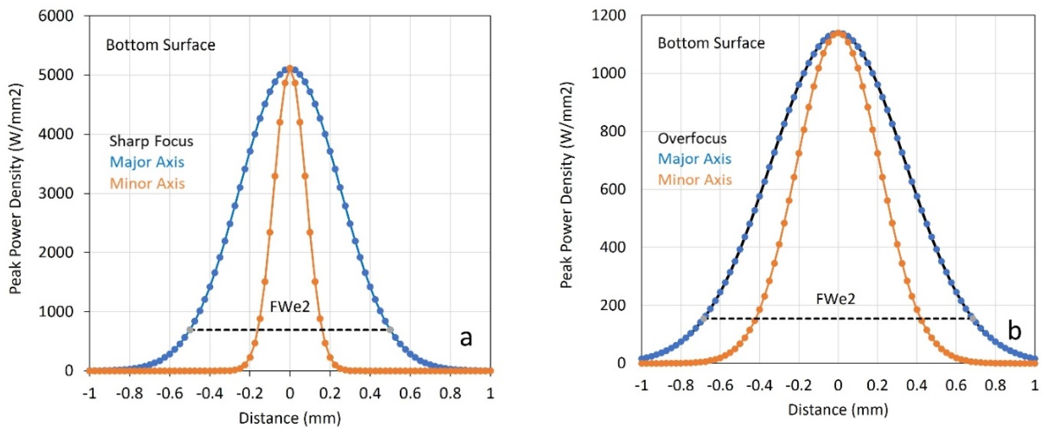
The electron beam welder was set up for two different beam configurations consisting of a sharp focused beam on the surface of the plate to be welded, and a defocused beam that was overfocused to approximately one-quarter of its peak intensity. The beam dimensions were characterised using the EMFC to determine the full width of the beam at half maximum of the peak (FWHM), the diameter of the beam at 1/e2 of the peak (FWe2), the peak power density (PPD), and two additional parameters that relate to the beam's symmetry and angular orientation in the electron beam chamber. In order to represent a non-circular beam shape, an Asterix is provided, FWHM* and FWe2*, which indicates the beam dimensions of a circle with the same area as the non-circular shape. 19 The FWe2* is considered to be the beam diameter and contains 86.5% of the beam's power, and is equivalent to the D4σ measurement for ideal circular beams.15,21 The beam's symmetry, as defined by its aspect ratio, is the length of the minor axis of the beam divided by its major axis. Values greater than 0.85 are considered to be circular, whereas values less than this are considered astigmatic elliptical. 21 The sharp and overfocused beams in this study were measured at two locations as schematically illustrated in Figure 1, corresponding to the plate surface ‘a’ and the position corresponding to the bottom of the plate ‘b’ to give an indication of beam's unimpeded divergence for reference.
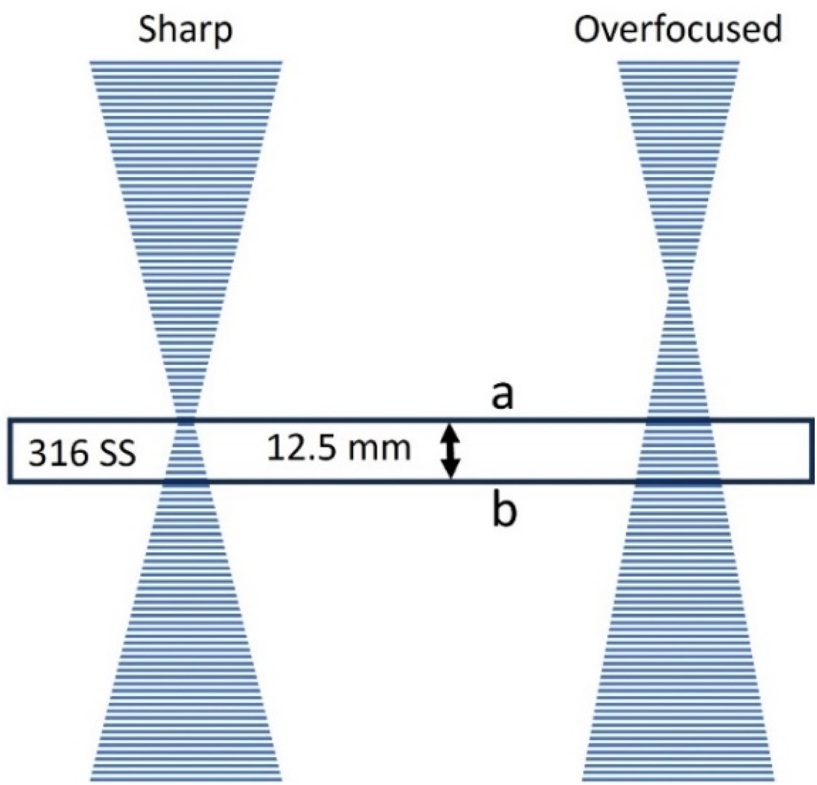
Schematic representation of the two different electron beam focus conditions.
Results and discussion
Electron beam spot weld observations
This study was initiated through observations of transient spot weld behaviour, where tacks are part of the normal welding procedure. Tacks on alloys that we typically weld such as steels, SSs, refractory metals, titanium alloys, aluminium alloys, and copper tend to be circular, but on occasion for SSs they are elliptical in shape for beams defocused above the surface of the weld. Experiments were performed to confirm this behaviour on one 316 SS heat using both a sharp focused and an overfocused beam that produced highly repeatable elliptical melt pool shapes. These beams will be referred to as the ‘sharp focus’ and the ‘overfocused’ beams throughout this paper.
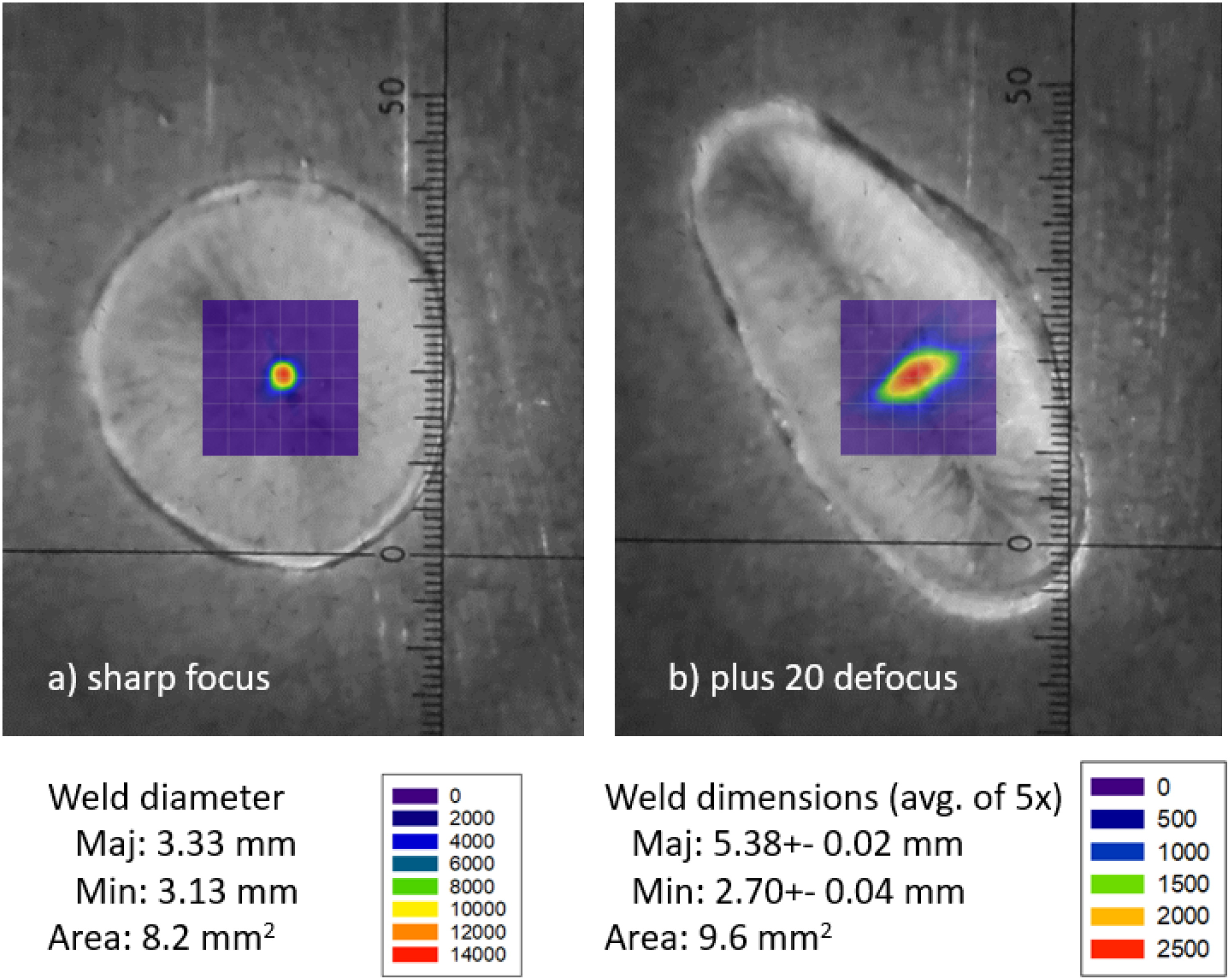
Photographic images of spot weld surfaces made using the two beams are shown in Figure 2. In these photos, 50 units in the scale equals 4.0 mm at this working distance, which corresponds to 0.080 mm per small reticle division. Both welds were made with a 1 s rise to peak power, and a 0.5 s hold at peak power before shutting off the here the melt pool was approaching what appeared to be steady state shape. Figure 2(a) shows the sharp focused beam weld indicating that it is substantially circular, with a 3.33 mm diameter across the major axis and 3.13 mm across its minor axis. The ratio of these two axes is 0.94, confirming its strong circular nature. Figure 2(b) shows the overfocused beam weld shape which is clearly elliptical. Measurements on five separate overfocused welds were averaged showing dimensions of 5.38 ± 0.02 mm along the major axis and 2.70 ± 0.04 mm across the minor axis. The ratio of the two axes is 0.50, indicating an ellipticity of 2:1. The area of the overfocused welds was measured to be 17% larger than the sharp focused beams at 9.6 mm2 versus 8.2 mm2.
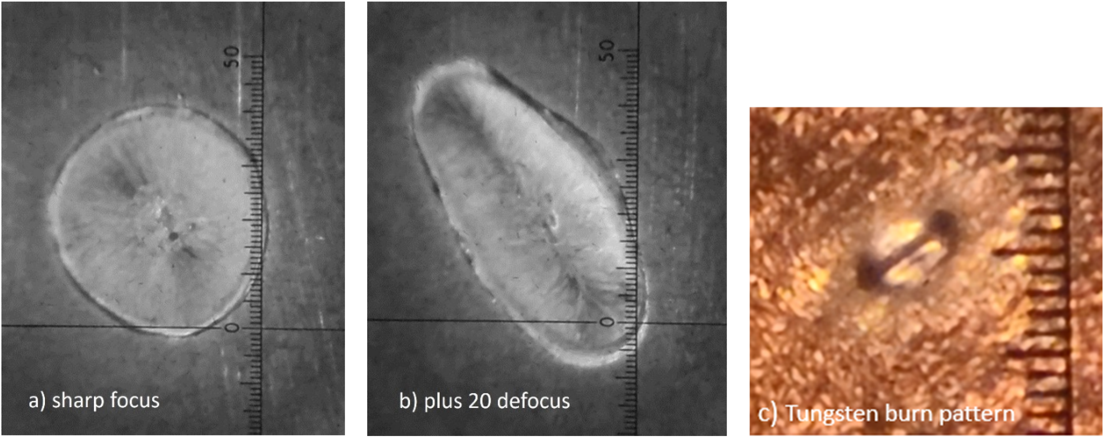
Images taken through the EB machine optics of (a) the sharp focused spot weld, (b) the overfocused spot weld, and (c) a short-duration burn pattern on a tungsten block of the overfocused beam for orientation verification of the beam's major and minor axes.
Electron beam characterisation
The power density distributions of the electron beams were measured with the EMFC diagnostic and are shown in Figure 3. In these figures, the colours represent the intensity of the beam in W/mm2, while the beam statistics are summarised in supplemental Table S-2. The sharp focused beam, Figure 3(a), has a PPD of 13,600 W/mm2, a FWe2* diameter of 0.31 mm and is substantially circularly symmetric. The overfocused beam, Figure 3(b), has a much lower PPD of only 2550 W/mm2 and is elliptically shaped with major (FWe2 maj) and minor (FWe2 min) diameters of 1.06 mm and 0.54 mm, respectively, an axis angle of 25.4 deg and an approximate aspect ratio of 2:1. Note that the beam diameter is only approximately 1/10 the diameter of the final melt pool shown in Figure 2. Further note that the major axis of the electron beam is oriented approximately 90 deg from the major axis of the overfocused melt pool ellipse. As confirmation of the beam's basic shape and orientation in the chamber, the overfocused beam was both viewed through the EB optics and a short-duration burn pattern was made on a high-melting-point tungsten target and is shown in Figure 2(c). The visual observations and burn patterns both confirm the beam's ellipticity and orientation of the beam as measured by the EMFC diagnostic.
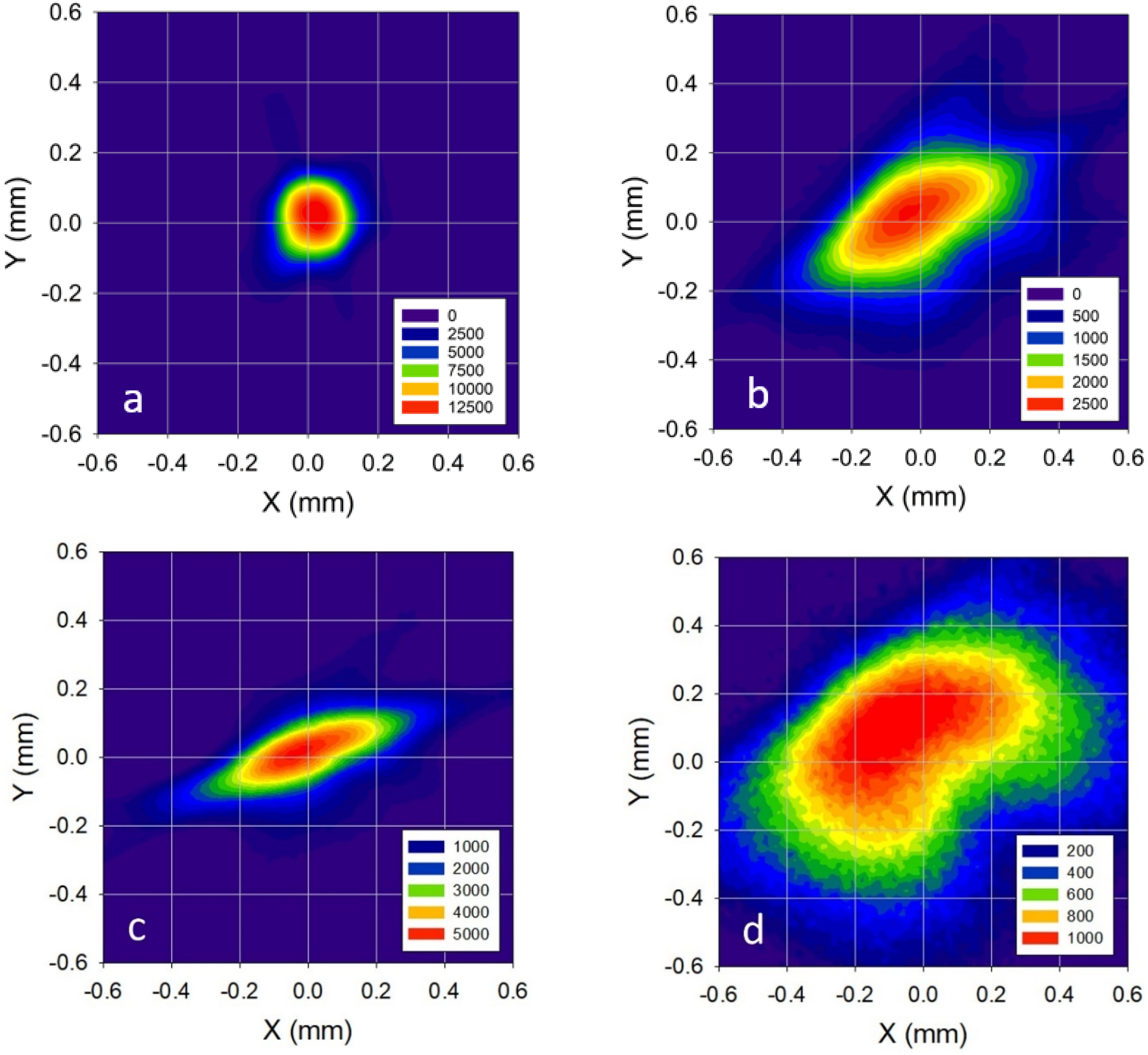
EMFC diagnostic measurements of the different beams and locations: (a) sharp focused beam top surface, (b) overfocused beam top surface, (c) sharp focused beam corresponding to the bottom plate location, and (d) overfocused beam corresponding to the bottom plate location. Power densities are coloured in the units of W/mm2. EMFC: Enhanced Modified Faraday Cup.
A second set of EMFC measurements were made at lens to work distance of 305 mm corresponding to the location on the back side of the plate as indicated as location ‘b’ in Figure 1 schematic. These contour plots are shown in Figure 3(c) and (d) and can be used to estimate the unimpeded beam divergence. It is clear that the sharp focused beam, Figure 3(c), now takes on an elliptical shape as it diverges past sharp focus, which is typical for this welder.15,22 The sharp focused beam's PPD has dropped more than 50% to 5110 W/mm2 at the location corresponding to the back side of the plate, and its shape measures 0.99 mm by 0.34 mm with an approximate doubling in area. The contour plot for the overfocused beam at the extended distance is shown in Figure 3(d), indicating that its PPD has also dropped by about a factor of 2 and it maintains an elliptical shape but with a lesser aspect ratio than at the location corresponding to the top surface, having major and minor axes of 1.37 mm and 0.84 mm, respectively.
Power density profiles across principal axes of the beams were calculated from the measured FWe2* power density distributions to estimate the power density gradients about each beam. These calculations are based on the Gaussian distribution, which is known to fit circular and elliptical electron beam shapes with centrally located peaks. 15 Figure 4(a) shows the sharp focused beam profile with a PPD of 13,600 W/mm2, and having a much smaller diameter than the overfocused beam's major and minor diameters that are also plotted for scale. Figure 4(b) zooms in on just the major and minor axes of the overfocused beam, and can be used to estimate the power density distribution gradient for each axis. Similar comparisons are made in Figure 5 for the locations corresponding to the bottom side of the plate. The beam that is sharp focused on the top surface is shown in Figure 5(a) and indicates that it now has an elliptical shape with major and minor axes indicated. Figure 5(b) shows similar plots for the overfocused beam, where the beam diverges to even larger diameters while the PPD drops from 2550 to 1140 W/mm2.
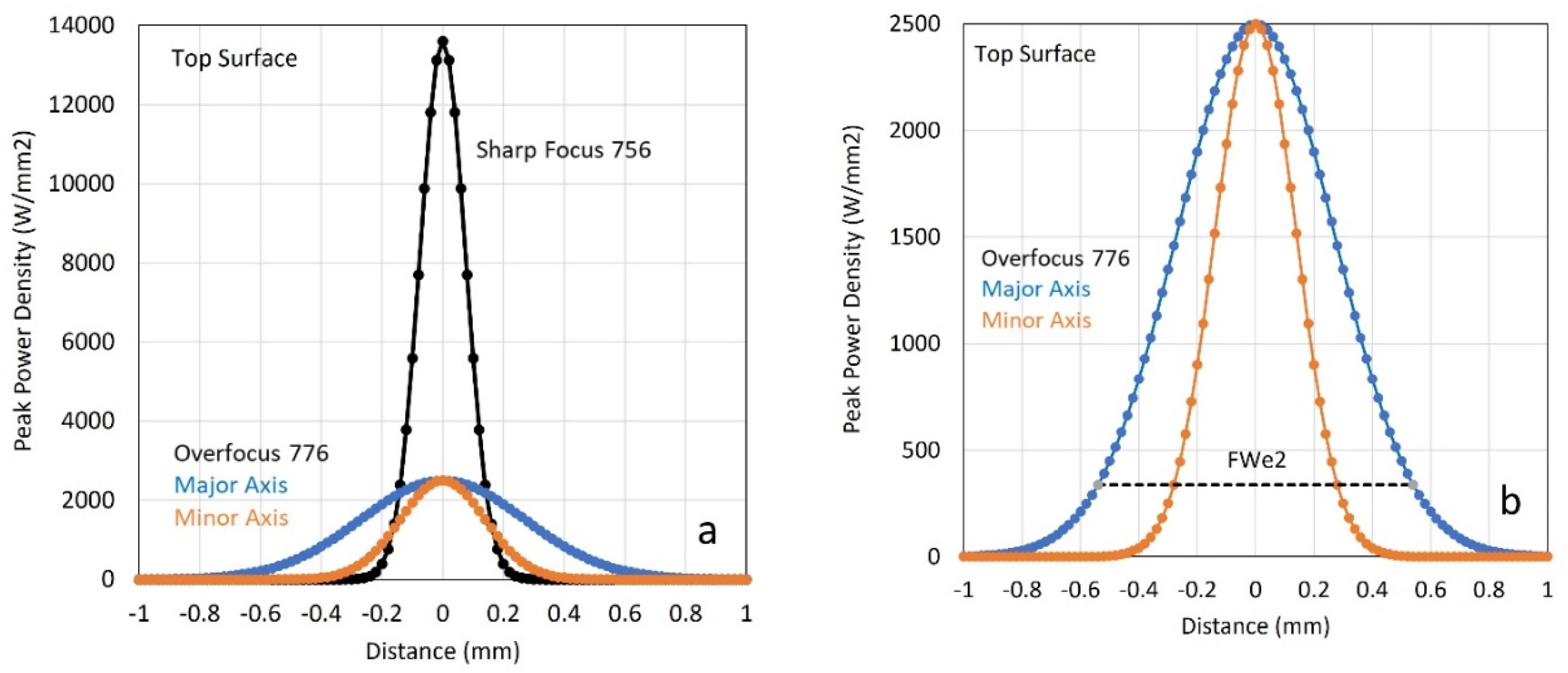
Gaussian beam power density profiles on the top surface of the plate for: (a) the sharp focused beam compared to the overfocused beam and (b) zoomed in major and minor axes of just the overfocused beam along their respective angles.
Gaussian beam power density profiles at a location corresponding to the bottom surface of the plate for the major and minor axes along their respective angles for: (a) the sharp focused beam and (b) the overfocused beam.
Melt pool shape and dimensions
Metallographic cross-sections were made on the sharp focused and overfocused beam spot welds to help understand the weld pool geometry. Figure 6(a) shows the top view of the sharp focused beam weld that has a circular shape, and its cross-section is shown in Figure 6(b). The melt pool is keyhole shaped with the penetration of 3.5 mm and top surface width of 3.3 mm, and is about 2x deeper than would be expected from a semicircular-shaped conduction-mode weld. This melt pool has a wider bowl on top of the keyhole, which is typical of a nail-head type geometry that would form during EB welding with the formation of a vapour cavity in the centre. The keyhole shape would not occur in lower power density spot welds that often have more semicircular cross-sections under conduction-mode heat flow conditions.4,13
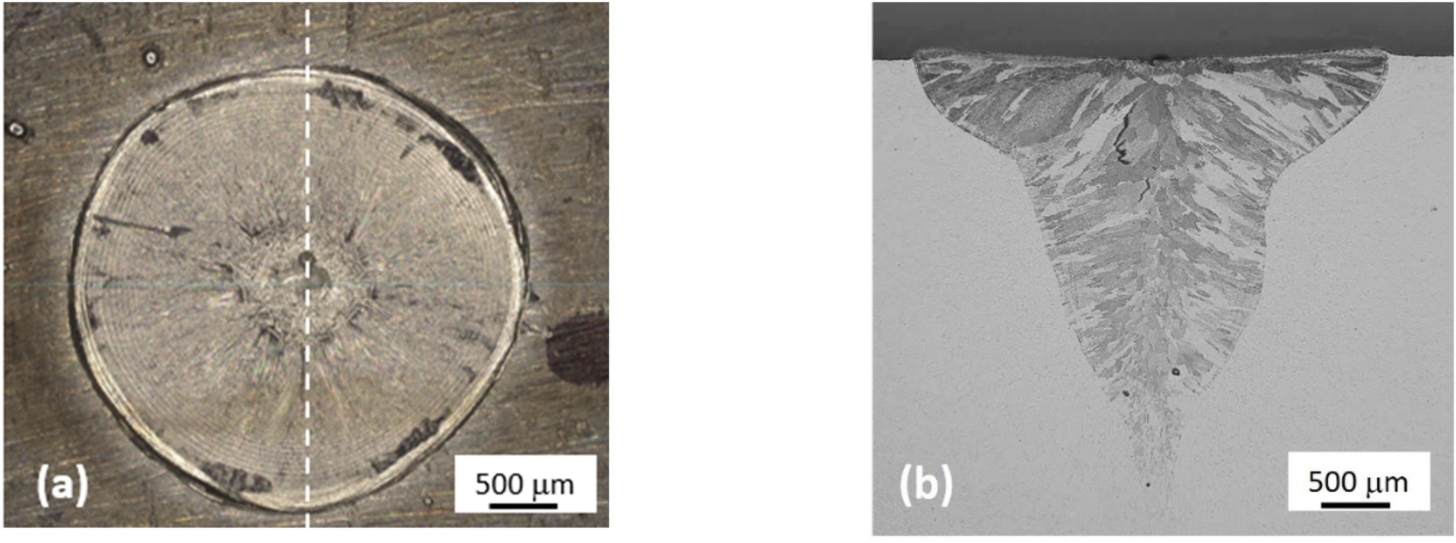
(a) Photograph of the top surface and (b) cross-section of the sharp focused circular-shaped spot weld across the dashed line shown in (a).
The overfocused beam welds were having elliptical shapes and were cross-sectioned through their major and minor axes. Figure 7(a) shows a top view of one of the welds, which has an aspect ratio of approximately 2:1, while Figure 7(b) shows this same melt pool in cross-section across its major axis. The shape of the melt pool is different than the sharp focused beam, having less penetration of 2.3 mm and a much wider top width of 5.4 mm. Figure 7(c) shows the top view of a second overfocused beam weld, while Figure 7(d) shows this weld in cross-section across its minor axis. In this cross-sectional view, the weld also has a depth of 2.3 mm but has tapered sides without much of a bowl on top. Its width is only 2.8 mm, which is less than that of even the sharp focused circular beam. It is apparent that melt pool convection is different for the sharp and overfocused beams where convection and forces acting on the liquid melt pool in the overfocused beam are creating conditions that elongate the weld pool in one direction near the surface of the plate.
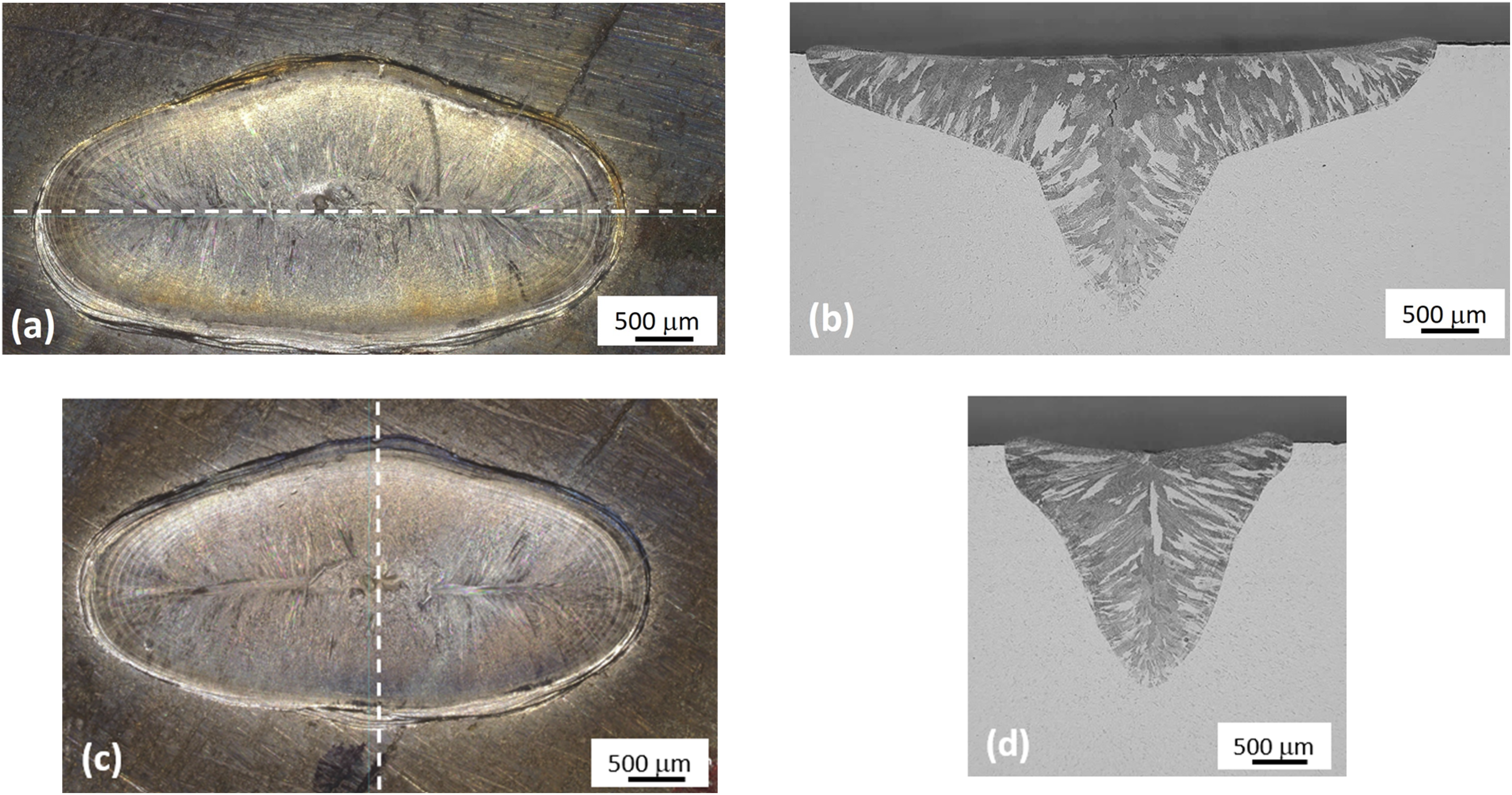
(a) Photograph of the top surface and (b) cross-section through the major axis of the overfocused beam spot weld. (c) Photograph of the top surface and (d) cross through the minor axis of the overfocused beam spot weld.
Weld pool convective forces have been studied in detail and are known to have a strong effect on the final weld pool shape under arc welding conditions.4,7,10,23,24 These studies, and others, show that surface active elements play a major role in convection and are known to alter the magnitude of surface tension driven fluid flow, which has also been observed in laser and electron beam welds in SS alloys.7,10 However, those and other similar studies relating to weld pool geometry25–27 do not mention or discuss the formation of elliptical-shaped melt pools like we are seeing in this investigation. Weld pool shapes are often modelled using a coupled thermal fluids approach to predict weld pool shapes based on welding parameters and material properties. Although these models may show weld penetration differences for different surface active element contents, for example, they do not indicate ellipticity to the melt pools.5,23,28 This is partly because most modelling efforts assume symmetric power distributions, whether it be electron beam, laser or arc, and as a result predict circularly symmetric weld pool shapes, and partly because modelling efforts tend to focus on moving welds with symmetry about the direction of travel,11,28 and do not capture the asymmetry of transient spot welds if it occurs.
An additional result of this study is summarised in Figure 8, which shows the top weld pool shape for both the sharp and overfocused beams, superimposed with the top surface power density distributions for each beam. The beams and weld pools are at the same scale and orientation, and clearly indicate that the beams are much smaller than the final weld size. In addition, the elliptical-shaped overfocused beam that produces the elliptical-shaped weld has an orientation where its axes are rotated 90 deg. relative to that of the weld pool. This behaviour was carefully examined for beam orientation relative to the weld pool both visually and with electron beam diagnostics for confirmation. The rotation of the major axis of the beam relative to the weld pool was repeatable for all the overfocused beam spot welds made in this study.
Top views of (a) sharp focused and (b) overfocused welds, with the actual size and orientation of the electron beam power density distribution superimposed on them. Power densities are coloured in the units of W/mm2.
Weld pool modelling considerations
The experimental evidence of elliptical-shaped weld pools shows an unexpected result that isn’t easily explained or obvious for the overfocused short-duration spot welds. This transient melt pool behaviour has been modelled in the past for sharp focused laser beams for example with a circular-symmetric power density distribution that produce circular-symmetric spot weld as would be expected.5,6 However, the elliptical-shaped overfocused electron beam in this study produces a complex melt pool shape that has a central keyhole appearance and an elliptical top surface that requires additional considerations to understand its formation. It is known that sulphur plays a major role in weld pool convection and the sulphur content of the 316 SS alloy studied here is 0.0095 wt%. This value is above 0.006 wt% where surface tension effects in 304L SS arc welds for example may create an inversion of the surface tension coefficient with respect to temperature. 7 At this sulphur level, Marangoni fluid flow would typically drive fluid flow towards the centre of the melt pool as seen in the sharp focused beam, not towards the edge as what appears to be occurring in the overfocused beam. However, other chemical considerations such as oxygen content and intermetallic S or O containing compound dissolution kinetics7,27 may need to be taken into account in the transient welds to describe the observed melt pool behaviours, but is beyond the scope of this investigation.
The experimental observations of this study could potentially be explained using computational thermal fluids modelling to understand the convective motion in the melt pool that produces the elliptical melt pool shape for the overfocused beam. Such models would need to not only consider Marangoni forces, but also take into account other forces acting on the melt pool such as the electromagnetic Lorentz force, 7 but it is not apparent to the authors that the effects of the Lorentz force have been applied to electron beam weld pool convection in the past. It is also worth noting that these calculations are complicated by the fact that a transient spot weld is constantly changing shape in time, never reaching a steady state for the short duration of these spot welds, which requires significant more computational complexity and time for the analysis compared to more traditional quasi steady state weld modelling approaches. No future work is planned at this time to model the observed behaviour, but it is hoped that the data presented here may be useful to other investigations of non-symmetric spot weld pool shape behaviour.
Conclusions
A 600 W (100 kV, 6 mA) electron beam was employed in this study to produce short-duration spot welds on a 316 SS plate using both sharp and overfocused beams. In the sharp focused condition, the beams power density distribution was shown to be circular at the point of impingement, whereas in the overfocused condition the beam had a different shape being non-circular with an ellipticity of approximately 2:1.
Transient spot welds used for tack welding were made with each beam showing different melt pool behaviours. Circular melt pool top surfaces were produced by the sharp focused beam, while elliptical melt pool top surface shapes were produced by the overfocused beam. Videos of the melt pool development in real time are available for both beam conditions as supplemental data.
Cross-sections of the melt pools showed keyhole behaviour with a nail-head appearance in both welds. The depth of penetration in the central portion of the sharp focused beam was approximately two times greater than it would be for a non-keyhole conduction-shaped weld pool, while the overfocused beam showed a much wider top along one axis of the weld and a deepened central keyhole.
Comparisons of the overfocused elliptical beam shape and the much larger elliptical melt pool shape that it produces, showed a counter intuitive behaviour in that the major axis of the melt pool is rotated approximately 90 deg. from the major axis of the elliptical power density distribution of the beam. This behaviour does not appear to have been documented before to the author's knowledge.
Numerical modelling of the observed transient spot weld behaviour with asymmetric beams is not prevalent in the existing literature, and perhaps represents a gap in the research, but such modelling and analysis is beyond the scope of this work.
Reducing the ellipticity of the electron beam by focusing the beam closer to its crossover position to produce a more circular power density distribution on the surface of the plate improved the symmetry of melt pools. This procedure is recommended if circular-symmetric spot welds are desired when produced by astigmatic defocused electron beams.
Supplemental Material
Supplemental Material
Supplemental Material
sj-docx-1-stw-10.1177_13621718251365288 - Supplemental material for Non-circular electron beam spot welds in stainless steel alloys
Supplemental material, sj-docx-1-stw-10.1177_13621718251365288 for Non-circular electron beam spot welds in stainless steel alloys by John W Elmer and Gordon Gibbs in Science and Technology of Welding and Joining
Footnotes
Acknowledgments
This work was performed under the auspices of the U.S. Department of Energy by Lawrence Livermore National Laboratory under Contract DE-AC52-07NA27344. Many thanks to James Embree, Lead Metallographer and Senior Technical Associate, of the LLNL Materials Engineering Division for the preparation of the metallographic cross-sections in this paper.
Declaration of conflicting interests
The authors declared no potential conflicts of interest with respect to the research, authorship, and/or publication of this article.
Funding
The authors received no financial support for the research, authorship, and/or publication of this article.
Supplemental material
Supplemental material for this article is available online.
References
Supplementary Material
Please find the following supplemental material available below.
For Open Access articles published under a Creative Commons License, all supplemental material carries the same license as the article it is associated with.
For non-Open Access articles published, all supplemental material carries a non-exclusive license, and permission requests for re-use of supplemental material or any part of supplemental material shall be sent directly to the copyright owner as specified in the copyright notice associated with the article.