
Abstract
Half-section welding has been proposed as a method to observe nugget growth throughout the resistance spot welding process. Some past studies used this technique as an in-situ monitoring approach to analyse the cracking behaviour during welding. However, there is a lack of understanding regarding the half-sectioned welding parameters, which critically impacts the liquid metal embrittlement cracking index. This study optimised half-sectioned welding parameters for liquid metal embrittlement crack analysis by developing process maps that compare the half-sectioned and full-section processes. It was found that the liquid metal embrittlement crack located at the weld shoulder can correlate to the temperature gradient in the heat-affected zone. This study proposes half-sectioned welding as a viable technique for liquid metal embrittlement analysis.
Keywords
Introduction
The automotive industry has been subjected to stringent regulations regarding carbon dioxide emissions to mitigate the impact of vehicles on the global environment. The use of third-generation advanced high-strength steel (3G-AHSS), allowing for thinner materials to be used in the body-in-white, has become a feasible solution in the automotive industry over the past two decades. 1 To improve corrosion resistance, 3G-AHSS is typically coated with various Zn-based coatings, such as galvanised (GI), galvannealed, and electro-galvanised. 2
Resistance spot welding (RSW) is the predominant joining process in the automotive industry. 3 Surface cracks could occur during RSW on Zn-coated 3G-AHSS because the melted liquid zinc formed by high heat input embrittles the grain boundaries of the steel substrate located near the coating layer, known as liquid metal embrittlement (LME) cracking. 1 The LME phenomenon is considered problematic, degrading the coherence of grain boundaries of ductile structural materials when a reactive liquid metal interacts with solid metal, leading to brittle failure under the applied tensile stress. 4 Particularly, the automotive industry has focused on the LME induced by the Fe–Zn interaction during the RSW process because the occurred LME crack during RSW drastically decreases the weld quality in terms of the mechanical properties. 1 Therefore, mitigating LME cracks of Zn-coated 3G-AHSS during RSW has remained a subject of great interest.
Researchers have attempted to understand the LME crack behaviour using various approaches such as thermomechanical simulations, finite-element simulations, and sectioning spot-welded joints.4–7 Thermomechanical simulation methods such as high-temperature tensile test (HTTT) can simplify the complexities associated with the RSW process.5,7 Significant loss of ductility shown in the stress–strain curves of Zn-coated 3G-AHSS at temperatures above 419°C (Zn melting temperature) was primarily attributed to the LME phenomenon. 7 The main drawback of analysing LME cracking using the HTTT test is the inherent differences in RSW thermal cycles and the simulated thermal cycles during HTTT tests. 6 Differences in HTTT parameters such as set temperature, hold time, and strain rate can result in discrepancies in the thermal cycles and LME cracking behaviour. Moreover, it has been shown that these parameters can influence the morphology and microstructure of the Fe–Zn intermetallic in the coating layer, which is critical to LME cracking behaviour assessment7,8 Discrepancies in the Fe–Zn intermetallic compound morphology between HTTT and RSW have been reported and attributed to different thermal cycles of each process. 6
In the case of finite-element modelling, DiGiovanni et al. 9 demonstrated that a correlation exists between electrode collapse and thermal stresses, especially in the shoulder area of the weldment. It was reported that high thermal stress promotes the formation of LME cracks. Nonetheless, the computed simulation cannot directly recreate the LME cracking during the RSW welding cycles as the conditions required to initiate and propagate LME cracking location are not well known.10,11
Half-sectioned RSW (H-RSW) is proposed to overcome the constraints associated with the existing methods for studying LME behaviour. Upthegrove and Key 12 developed the H-RSW process to observe weld nugget formation behaviour during welding using a high-speed camera for in-situ monitoring. Subsequent studies related to the H-RSW process revealed that RSW process parameters for the H-RSW setup, such as weld current and electrode force, had to be adjusted to replicate full-section RSW (F-RSW).11,13 However, there exists a lack of understanding about the optimised condition for H-RSW.11,14–16 The existing studies neither consider parameter optimisation for H-RSW, nor the effect of welding parameters on thermal cycle, which is critical to LME cracking during RSW. Leading to the impact of process parameter combinations on the thermal cycle remaining unexplored. Therefore, the process window relating to the resulting weld dimensions between the H- and F-RSW parameters is necessary to understand the inherent differences between the H- and F-RSW thermal cycles. Moreover, defining the quantitative difference between both weld geometries is important to establish a connection between them, especially when defining the LME cracking mechanism using H-RSW.
This study developed the optimised H-RSW parameters to facilitate in-situ LME observations, achieved through harmonisation of the indentation depth, and LME cracking index (CI), with F-RSW 3G-AHSS. Particular attention was given to considering the thermal cycles using developed process windows for nugget diameter, indentation depth, and LME CI. Moreover, the microstructure of H-RSW via two different directions was investigated and the relationship between temperature gradients in critical LME-susceptible regions was identified. The thermal gradient strongly influences the LME cracking behaviour in the shoulder of the welds and these shoulder area cracks negatively affect weld performance. 17 As it was shown that the electrode-to-sheet surface contact affects thermal stresses during RSW, 12 this study opts to compare the LME severity of the shoulder region of the half-section welds using different sets of process parameters.
Experimental procedure
Materials
This study investigates the LME response of a 1.6 mm thick GI-coated 3G-AHSS in a homogeneous two-thickness (2T) stack-up. The base-metal (BM) microstructure consists of a ferritic matrix with tempered martensite and bainite. The chemical composition and carbon equivalent developed by Yurioka et al. 18 are illustrated in Figure 1(a) and (b).
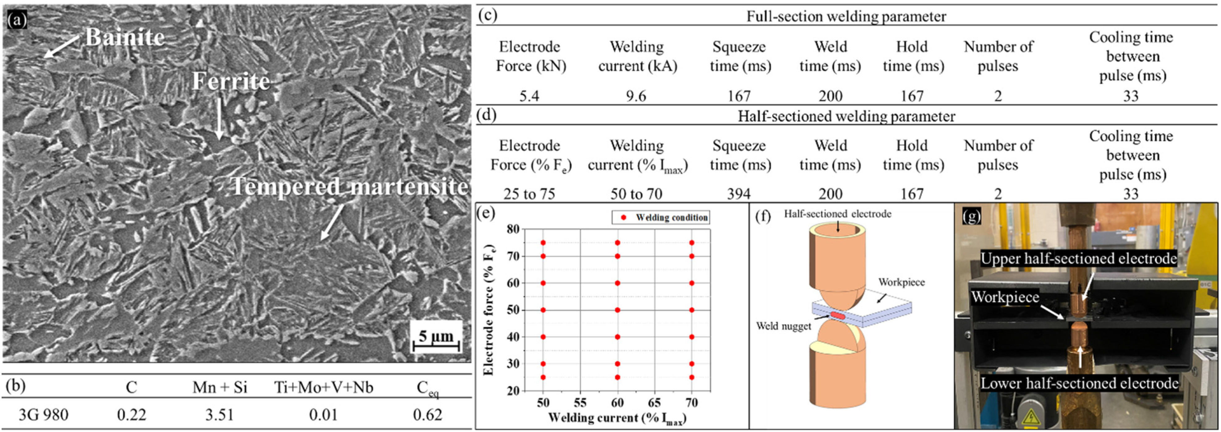
(a) BM micrographs of investigated 3G-AHSS; (b) chemical composition and Ceq; (c) baseline F-RSW parameters; (d) H-RSW parameters; (e) investigated process parameters for H-RSW; (f) schematic representation of H-RSW developed in this study, and (g) H-RSW experimental setup.
Resistance spot welding
RSW was performed using a medium frequency direct current Honda robotic spot welder (R-2000ic) with an industrial C-type welding gun and a Bosch Rexroth controller. The electrodes used in this study were Resistance Welding Manufacturing Alliance type B (dome radius type) with a 6 mm face diameter. The electrodes were continuously water-cooled via a nominal flow rate of 6 L/min. This study investigates resistance spot-welded joints in two conditions: F- and H-RSW. The specimens for F-and H-RSW were sheared into 25 mm × 25 mm coupons and cleaned with acetone before welding. The following two sections explain details regarding each of these conditions and the corresponding RSW process parameters.
Full-section resistance spot welding
The welding parameters of F-RSW are considered as the baseline condition to optimise the H-RSW parameters accordingly. The maximum welding current (Imax) of 9.6 kA was selected for the F-RSW to increase the opportunity of initiating LME crack without the occurrence of expulsion. The Imax welding current value is 0.1 kA below the expulsion current, which was confirmed via three consecutive welds without an expulsion. The electrode force (Fe) of 5.4 kN was chosen considering the load application capacity of the servo-gun. Different sets of RSW process parameters were used for the F-RSW as outlined in Figure 1(c). These parameters were selected based on the recommendations of AWS D8.9.
Half-sectioned resistance spot welding
In the H-RSW condition, all parameters were based on those used for the F-RSW. However, modifications were made to accommodate the edge welding geometry. The electrodes used for H-RSW were milled in half as shown schematically in Figure 1(f) and (g). The reduced electrode-to-sheet contact in the H-RSW alters the heat input and nugget growth trends compared with the F-RSW. Consequently, the H-RSW parameter was selected by off-setting the baseline parameters of F-RSW and had to be optimised by developing a process window. A total of 21 experimental permutations were explored using three different welding currents (50%, 60%, and 70% of Imax) and seven different electrode forces (25%, 30%, 40%, 50%, 60%, 70%, and 75% of Fe) as illustrated in Figure 1(d) and (e). Note that the squeeze time for H-RSW was greater than that used for the F-RSW to improve the stability of the sheet-to-sheet interfacial area, but the weld and hold time for both geometries were the same.
Characterisation
The specimens for F-RSW were cross-sectioned along the centreline and hot-mounted in epoxy resin. Specimens were polished to a 1 µm diamond suspension finish using conventional metallographic procedures and etched with a 2% Nital solution. Optical microscopy was conducted using a Keyence VHX digital microscope to observe the welds’ LME cracks and microstructural and geometrical evolution. Electron micrographs were captured using a Zeiss UltraPlus Field emission scanning electron microscopy (SEM). The open-source software Image J, version v1.53t, was used for measuring the crack lengths, indentation depths, and nugget diameters. In the case of H-RSW, an extruded nugget was formed at the open-edge surface. The extruded portion of the solidified nugget had to be removed before any microstructural analysis via grinding along the XZ-plane, as shown in Figure 2. Moreover, it was observed that, unlike F-RSW, the H-RSWs are non-symmetrical in terms of LME cracking behaviour and heat-affected zone (HAZ) size in two directions. Therefore, the specimens were sectioned into two planes as shown schematically in Figure 2: the ZY cutting plane and the XZ grinding plane. Note that the procedure for specimen preparation was the same as for F-RSW specimens.
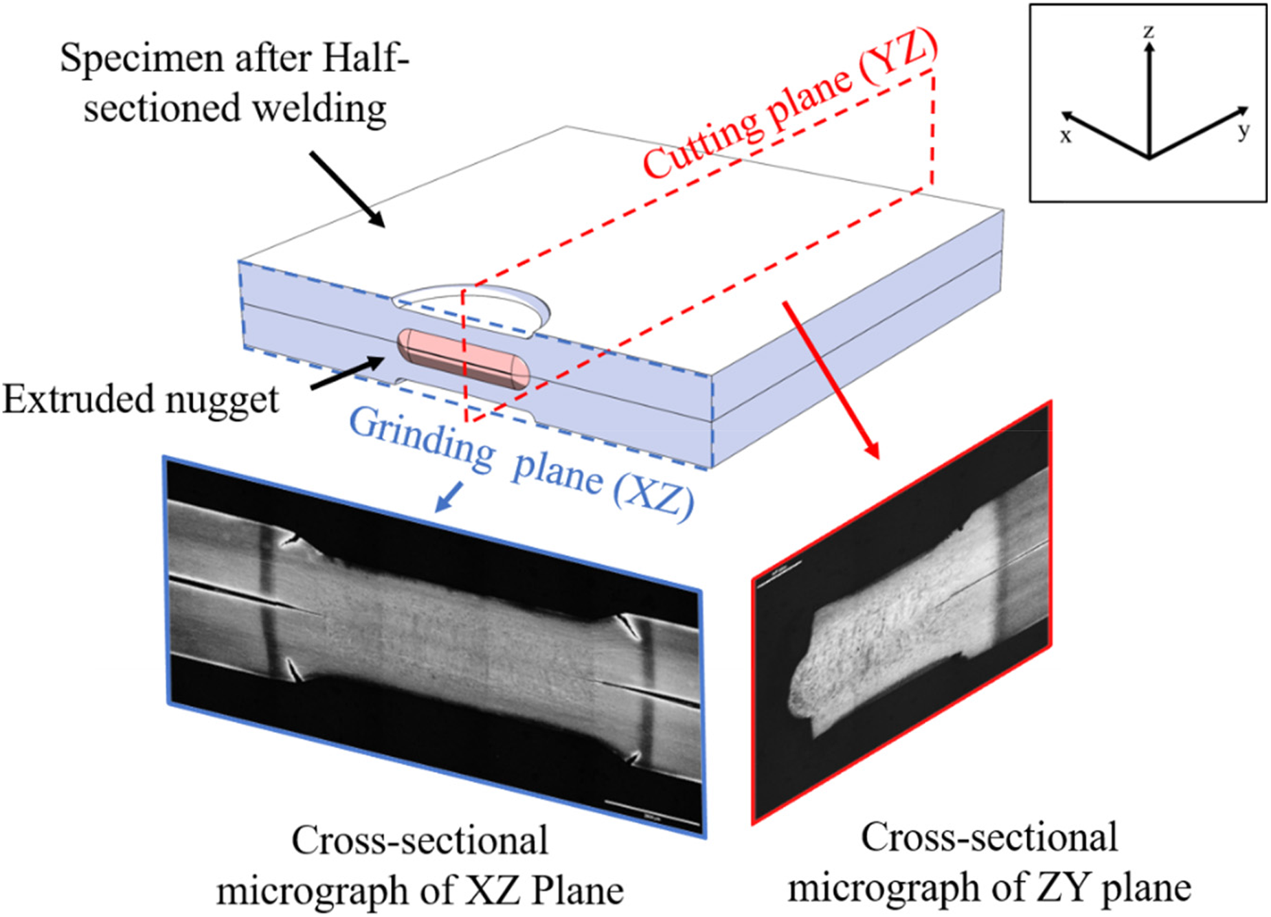
Schematic drawing of a half-sectioned resistance spot welding (H-RSW) specimen showing the grinding and cutting planes along with optical micrographs for the corresponding planes.
Physical attributes of spot-welded joints, such as nugget diameter and indentation depth not only impact the joint's quality but also correlate to electrode-to-sheet contact behaviour, which is related to the thermal cycle in the shoulder area.11,19 Therefore, nugget diameter and indentation depth were used as comparative indexes to match H-RSW parameters to those of F-RSW. Indentation depth was measured from the horizontal line with the BM's edge to the electrode imprint's depth. The nugget diameter was measured from notch to notch.
To analyse the LME cracking behaviour, the crack length (CL) and maximum CL (MCL) were measured from the cross-sectional image of each specimen. The LME CL was measured by drawing a straightline from the root of the crack to the tip. At least three repeats of each welding condition were analysed to determine the average weld diameters, indentation depths, CL, and MCL resulting from each weld schedule. The reported LME crack counts and lengths are averages of measurements from three RSW specimens, and the corresponding error bars are standard deviation values. The LME cracking severity was quantified using the CI equation proposed by Wintjes et al.
20

Results
The nugget diameter, indentation depth, and LME CI of the F-RSW were 7.20 ± 0.63 mm, 0.35 ± 0.03 mm, and 1.02 ± 0.06, respectively, which were used as the baselime metrics. Weld dimensions and LME CI resulting from parameter adjustments during H-RSW were compared with these values to determine the optimal H-RSW parameters.
Effect of welding parameter on joint geometry in half-sectioned welding
Figure 3 shows that both welding current and electrode force directly influence the indentation depth and nugget diameter of the H-RSW. The horizontal dashed lines indicate the baseline indentation depth and the nugget diameter measured from the F-RSW. The H-RSW achieves much higher indentation depths than the F-RSW because of the open plane's inability to build pressure in molten nuggets and counter the welding force. The tendency of indentation depth increased with increasing welding current as shown in Figure 3(b). In the case of the 50% Imax condition, the indentation depth increased with increasing electrode force until 50% Fe. Thereafter, a decreasing trend was observed for 60% and 70% Imax conditions. Indentation depth decreased with increasing electrode force until 60% Fe, and slightly increased after this point, as shown in Figure 3(b). Increased electrode force decreases contact resistance at the faying interface, as reported by Kimchi and Phillips, 3 which leads to decreased nugget diameter size. The nugget diameter increased with increasing weld current, but decreased with increasing electrode force, as shown in Figure 3(a). In the case of 50% welding current, an insufficient nugget diameter was observed after 40% Fe.
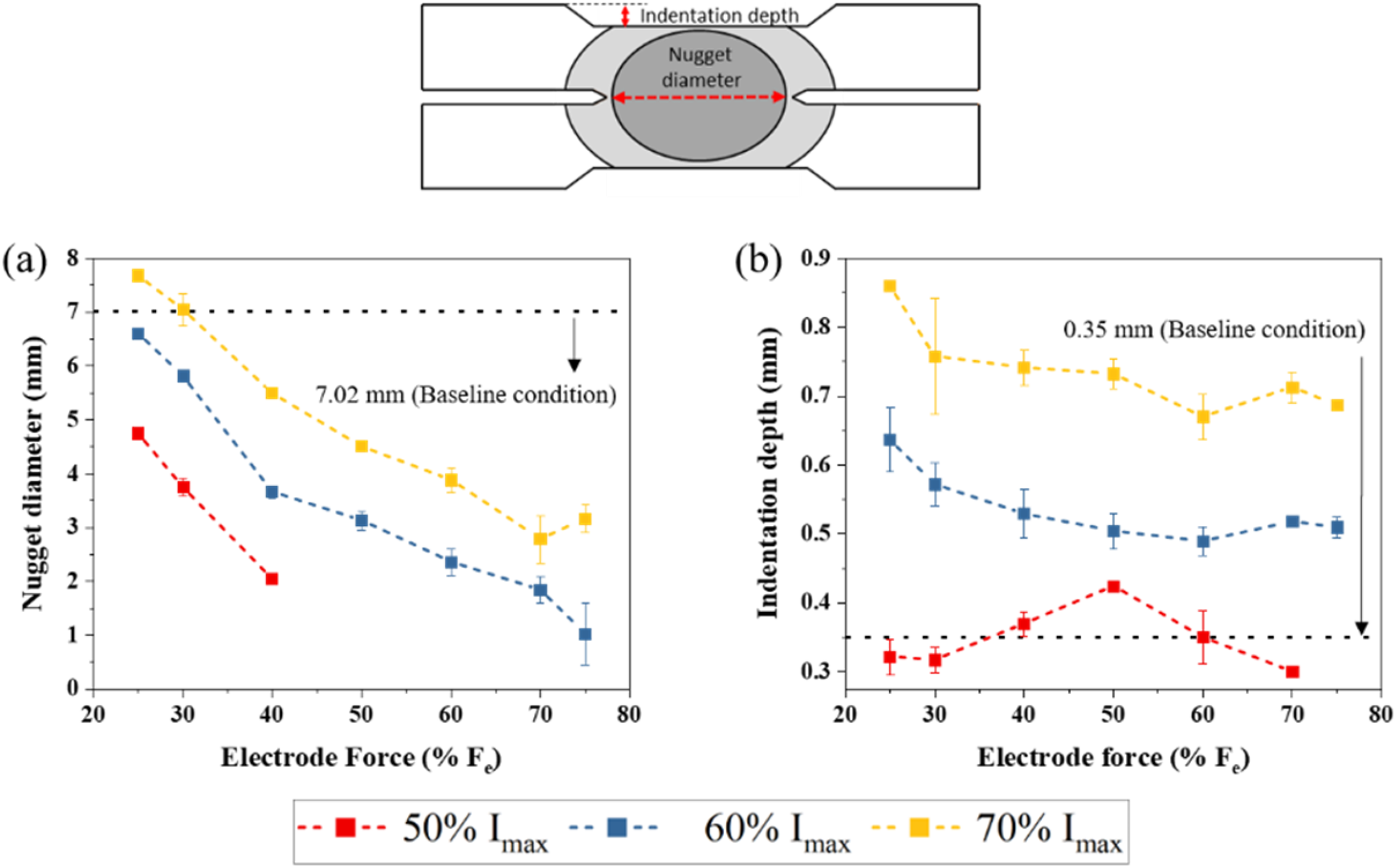
Effect of RSW electrode force on (a) nugget diameter and (b) indentation depth of H-RSW (Imax = 9.6 kA).
Process map for half-sectioned spot welds
A process map illustrating the nugget diameter and indentation depth was plotted to determine the optimised parameters for the H-RSW technique, as depicted in Figure 4(a) and (b). The red dashed lines indicate the baseline average nugget diameter and indentation depths (7.2 and 0.35 mm, respectively). Indentation depth was compared between the F- and H-RSW conditions to have the best similarity between the conditions during their respective thermal cycles; especially in the shoulder area. 5 The differences in thermal cycles originate from the heat dissipation towards the open surface during the H-RSW.13,15 In the case of nugget diameter, two welding conditions, 25% Fe, 70% Imax (1.35 kN, 6.72 kA) and 30% Fe, 70% Imax (1.62 kN, 6.72 kA), match the baseline's nugget diameter, and these conditions were indicated using yellow boxes c and d in Figure 4(a). However, the aforementioned conditions exhibited much higher indentation depths and defects (fusion zone (FZ) porosity), compared with the baseline condition. Likewise, four conditions corresponding to pink boxes e to h have the most comparable indentation depths with the baseline condition. Nevertheless, the welds produced through the H-RSW had smaller nugget diameters compared with the baseline welds. This indicates that reproducing the exact thermal cycle of F-RSW may not be achievable through this method. However, it is feasible to identify the welding parameter combination that results in similar LME cracking behaviour by referring to the CI map of H-RSW.
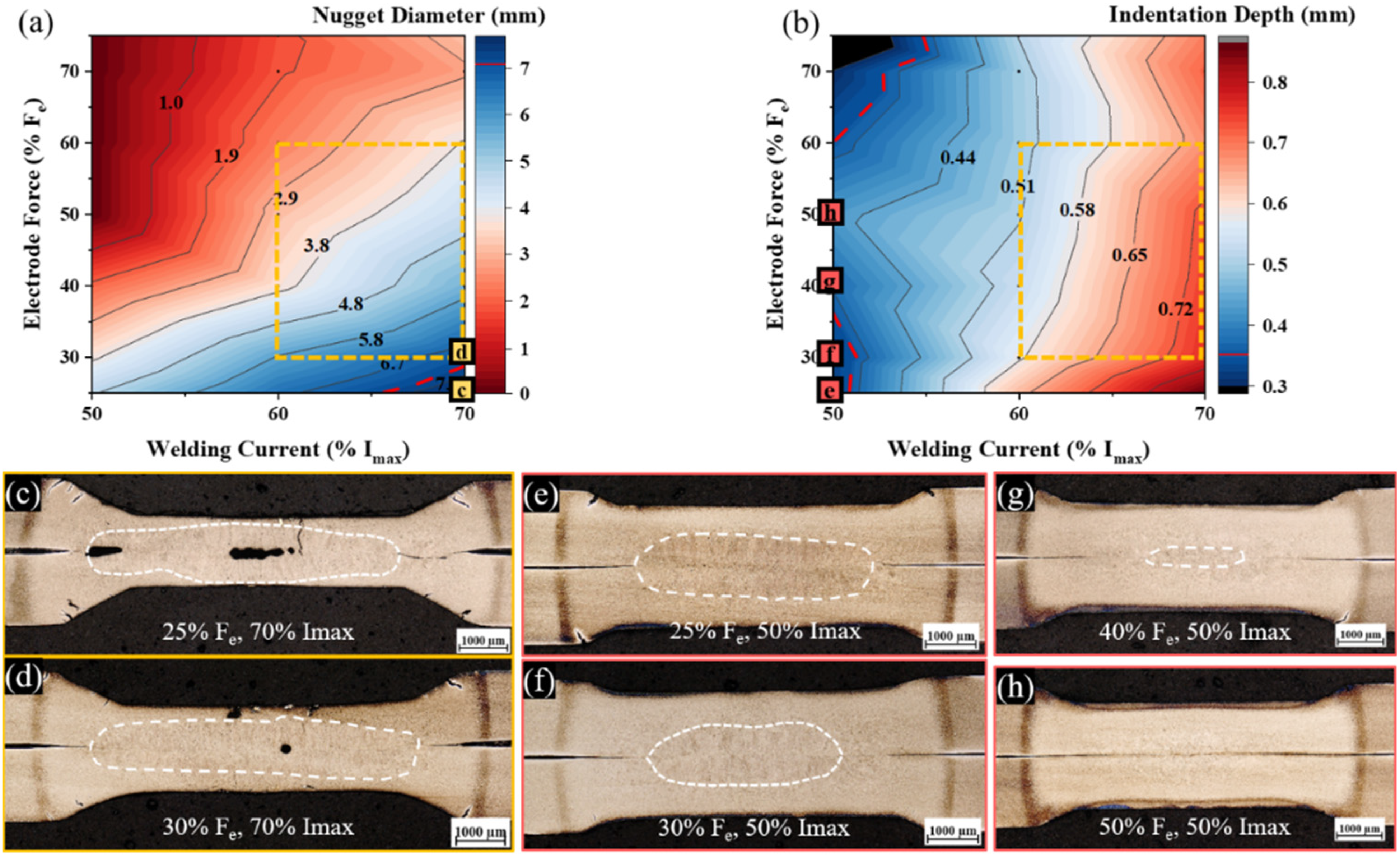
Half-sectioned resistance spot welding (H-RSW) process window for (a) nugget diameter and (b) indentation depth as a function of welding conditions. Cross-sectional optical images of different welding conditions including (c) 25% Fe, 70% Imax, (d) 30% Fe, 70% Imax, (e) 25% Fe, 50% Imax, (f) 30% Fe, 50% Imax, (g) 40% Fe, 50% Imax, and (h) 50% Fe and Imax.
LME cracking behaviour in half-sectioned spot welds
Figure 5(a) shows the LME CI map in the shoulder area of the H-RSW. A red dashed line indicates the baseline's CI value of 1.02 ± 0.06. It was understood that the conditions within the dashed yellow box in Figure 5(a) possess CI values within 11% of the F-RSW (namely 25% Fe and 50% Imax, 30% Fe and 60% Imax, 60% Fe, and 70% Imax conditions). The tendency of cracking behaviour appears to be affected not only by both nugget diameter and indentation depth but also by a complex relationship between nugget diameter and the indentation depth. In the case of 25% Fe electrode force, most conditions have higher CI values compared with the baseline regardless of indentation depth, and the nugget diameter of those conditions was above 4.8 mm. The tendency of LME CI in the dotted rectangle area (Figure 5(a)) shows high dependency on indentation depth (dotted rectangle area in Figure 4(a)), but the nugget diameter decreases in the dotted rectangle area in Figure 5(b), the value of the CI decreased. The observed relationship between indentation depth and LME cracking behaviour is similar to the trends reported by Song et al. 19 The welding condition of 25% Fe and 50% Imax has the closest indentation depth to the target, referred to as CI-H-RSW from here onwards. However, the LME cracking behaviour was different, especially concerning the MCL. The average MCL of F-RSW was 88.1 ± 8.6 µm, whereas the MCL of H-RSW was 464.4 ± 82.05 µm. In the case of F-RSW, 25.6 cracks were measured on average with medium LME CL (30 µm < CL < 100 μm). On the other hand, a combination of large- (CL > 100 μm) and medium-sized LME cracks was observed in the half-sectioned cases. More specifically, 4.6 large- and 6.3 medium-sized cracks per weld were estimated on average. These observations indicate that the LME cracking behaviour, affected by the thermal cycle, is different between F- and H-RSW. The thermal cycle could be correlated with the microstructural evolution during the welding process as discussed in the following.
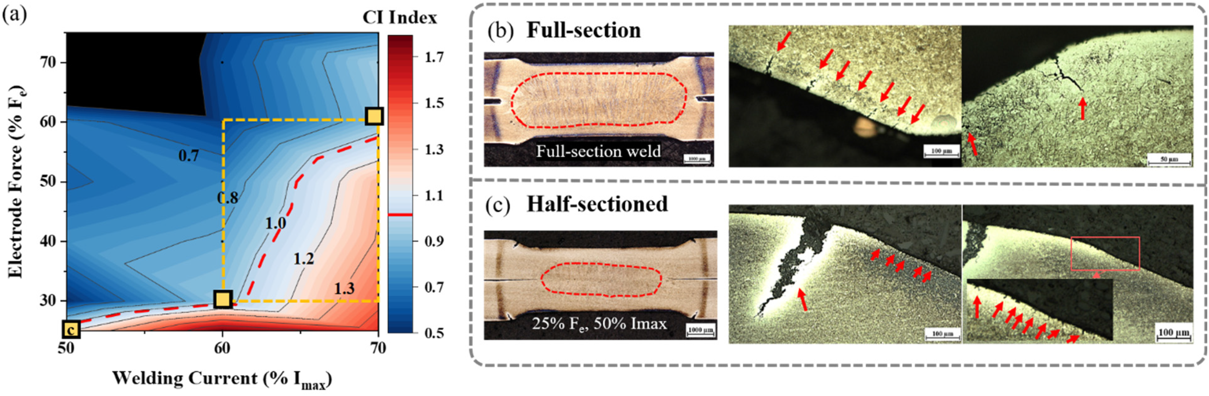
(a) LME CI map during H-RSW with various welding parameters. Cross-sectional images showing LME cracks in (b) F-RSW and (c) H-RSW schemes.
Discussion
Microstructural evolution in half-sectioned weld
Typically, the thermal cycle could be studied through the analysis of microstructural evolution. Microstructural analysis was performed in this section to quantify the differences in HAZ size of F- and H-RSW conditions. Twenty-five percent (25%) Fe and 50% Imax, which have similar CI and indentation depth with the baseline's (CI-H-RSW) were selected for further analysis. Regions were distinguished according to the observations from etched optical and SEM micrographs in Figure 6(a) and (b) for H- and F-RSW, respectively. The developed microstructures during RSW can be subdivided into the FZ, HAZ, and unaffected base material (BM). These regions and their approximate corresponding temperature regime have been schematically shown in Figure 6(c). The microstructure of FZ in both F- and H-RSW is composed of a fully martensitic structure and oriented towards the nugget centreline in the opposite direction of the heat dissipation as shown in Figure 6(a) and (b). Similarly, the coarse-grained heat-effected zone (CGHAZ) and fine-grained HAZ (FGHAZ) also consist of martensite, but the grain size of CGHAZ determined by the prior austenite grain boundary is larger than that of the inter-critical HAZ (ICHAZ) and it was confirmed by the SEM micrographs as shown in Figure 6(a1), (a2), (b1), and (b2). ICHAZ consists of a mixture structure with bainite, martensite, and ferrite as displayed in Figure 6(a3) and (b3). Based on the microstructure characteristic, the weld regions can be divided by four borders: border 1 (B1) divides the FZ and CGHAZ, while border 2 (B2) divides the CGHAZ and FGHAZ, border 3 (B3) is located in between FGHAZ and ICHAZ, border 4 (B4) separates the ICHAZ and sub-critical heat affected zone (SCHAZ). As the shoulder LME cracks are of interest in this study, the distance from the fusion boundary (FB) to ICHAZ was measured to represent the thermal cycle, which affects the shoulder LME cracking behaviour during the welding 21 ; it was marked as a red arrow in Figure 6(a) and (b). The ICHAZ was selected as a measurement basis since it formed at the end of the shoulder region in the investigated welds; the values are shown in Figure 6(d). The distance from FB to ICHAZ measured in CI-H-RSW was 1.70 ± 0.18 mm, whereas the distance from the FB to the ICHAZ in F-RSW was 0.81 ± 0.07 mm. This means that the thermal cycle behaviour related to LME cracking formation is different between F- and H-RSW. The differences in thermal cycles between the H- and F-RSW are attributed to two heat dissipation mechanisms. The first is axial heat dissipation, which occurs towards the water-cooled electrodes, while the second is radial heat dissipation, which happens through the open surface of the H-RSW. Consequently, the H-RSW has a smaller nugget size but a wider HAZ area in comparison with the F-RSW. It is widely acknowledged that RSW is a symmetrical welding process. However, it was found that H-RSW is inherently non-symmetrical, as shown in Figure 7, which implies a directional characteristic in the H-RSW. To observe the weld growth away from the free edge, the weld was cross-sectioned perpendicular to the free edge (referred to as the YZ-plane) and compared with the nugget diameter as measured from the free edge (referred to as the XZ-plane), see Figure 7(a). Nugget diameters are similar for both cutting planes, but a 0.63 mm difference exists in the average distance from FB to ICHAZ as shown in Figure 7(b). This leads to the conclusion that each plane has a different thermal cycle behaviour because of the heat dissipation from the open surface. Therefore, the difference in heat dissipation results in a similar nugget diameter with wider HAZ in the YZ-plane. The length of HAZ near the sheet surface indicates that the temperature gradient during welding and the wider HAZ can significantly affect the electrode-to-sheet contact behaviour, which highly influenced the LME cracking behaviour in the shoulder area. The relationship between the size of HAZ and the cracking behaviour in the XZ and YZ planes is illustrated in Figure 7(c). It was observed that the wider HAZ (YZ-plane) has less LME CI than the XZ-plane. This observation indicates that the thermal cycle and HAZ area are directly related to LME cracking behaviour during the RSW.
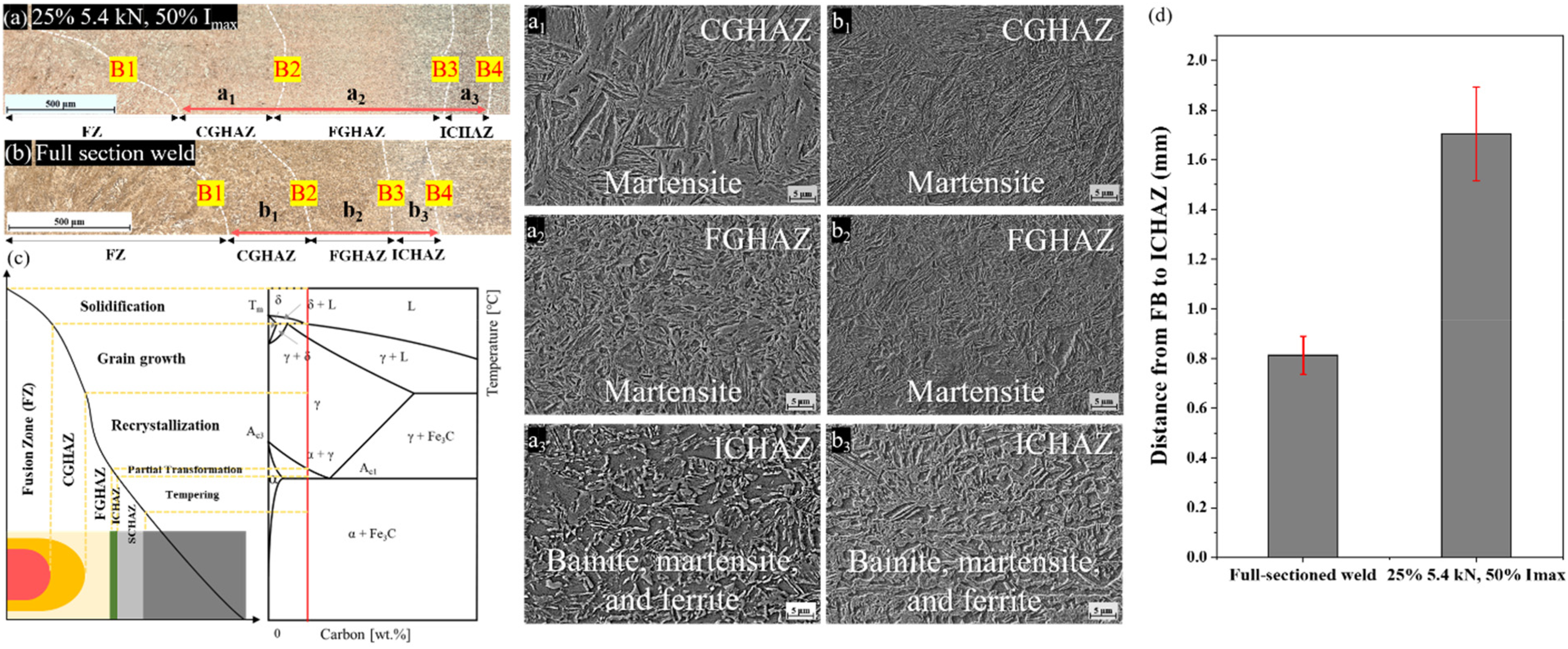
Microstructure evolution in (a) H-RSW of 25% Fe, 50% Imax, and (b) F-RSW. Electron micrographs of H-RSW sample at (a1) CGHAZ, (a2) FGHAZ, and (a3) ICHAZ and of F-RSW at (b1) CGHAZ, (b2) FGHAZ, and (b3) ICHAZ. (c) Typical RSW subregions along with their corresponding temperature range. (d) The distance from FB to ICHAZ bar graph as a function of weld process parameters.
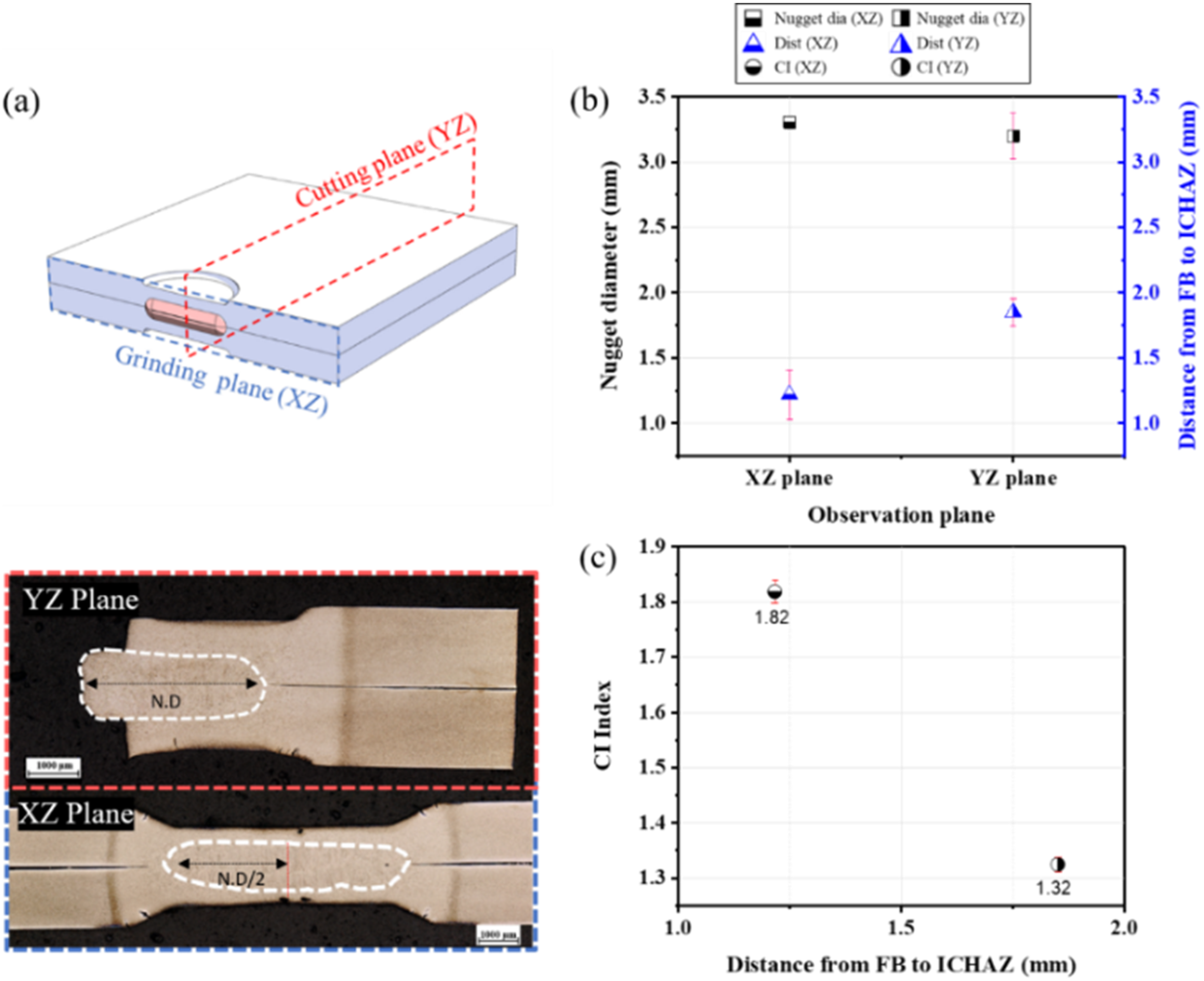
(a) Schematic drawing of a H-RSW along with optical micrographs of cutting planes; effect of cutting plane on (b) nugget diameter, and (c) CI index.
Correlation between LME cracking behaviour and temperature gradient
Distance from FB to ICHAZ is related to the thermal cycle, specifically with temperature gradient and the LME cracking behaviour located in the shoulder area, as discussed in the previous section. The distance from FB to ICHAZ can be converted to the temperature gradient using equation (2) with temperatures obtained from JMatPro software. Where Tmelt is the melting temperature of the investigated 3G-AHSS (1486°C) representing the temperature at the FB, TICHAZ is the temperature at the end of ICHAZ (720°C) corresponding to the Ac1, and Δx is the distance from FB to ICHAZ. The relationship between CI and distance from FB to the ICHAZ was plotted in Figure 8(a). It is shown that the H- and F-RSW have different LME cracking behaviour due to the different thermal cycles. Even though the HAZ area in F-RSW is smaller than that of H-RSW, the CI is lower than that of H-RSW. In the case of the H-RSW, the CI decreases with increasing the distance from FB to ICHAZ. It is believed that the constrained environment in F-RSW affects the CI value. Whereas in the H-RSW, less constraint is applied to the fusion region resulting in a higher CI value shown in Figure 8. Further investigation of this discrepancy will be the focus of future studies strength steel.

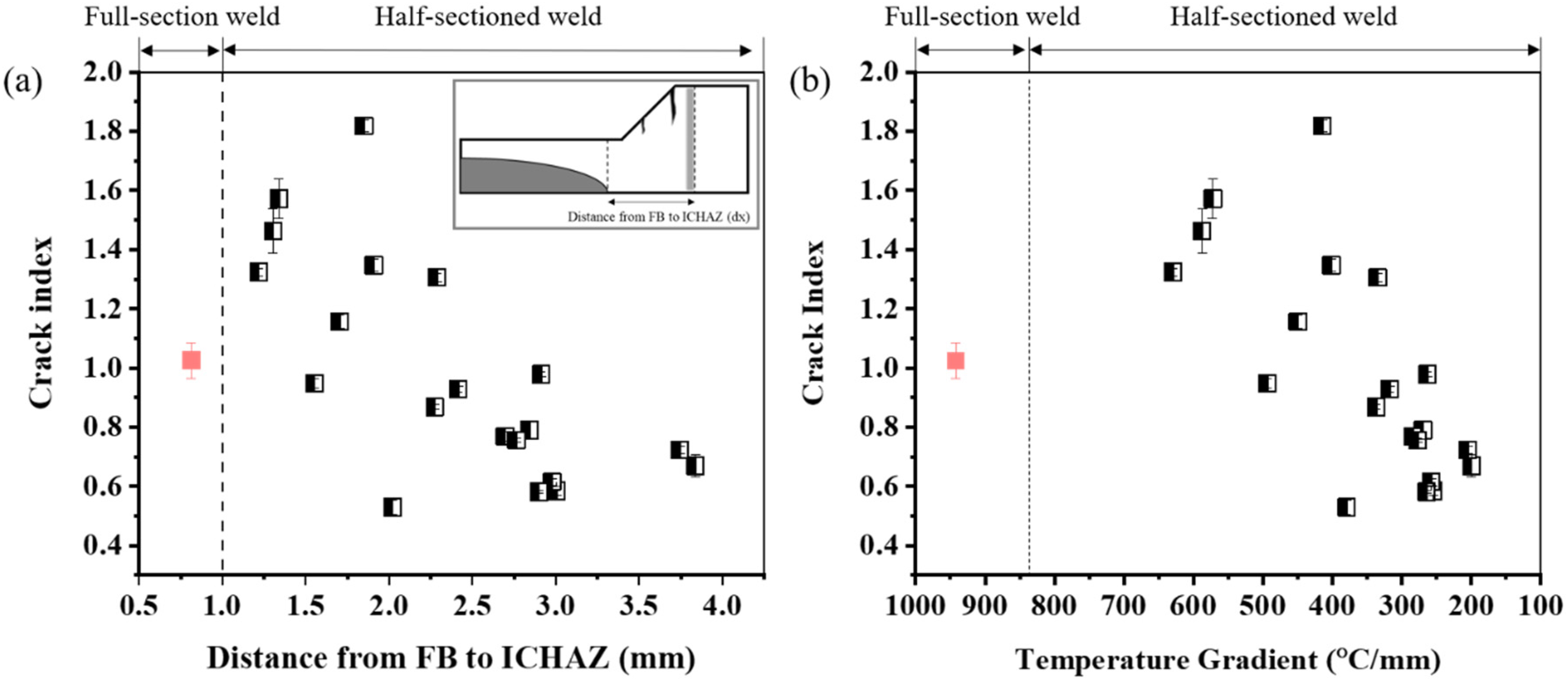
CI via distance from FB to ICHAZ (a), and the temperature gradient via CI (b).
The CI is highly related to the temperature gradient as shown in Figure 8(b). It can be concluded that the H-RSW provides a more extreme environment for LME cracking. This implies that H-RSW can be selected as a viable option to analyse the LME cracking behaviour because it results in a more severe condition for LME formation, even though the thermal cycle of F-RSW could not be precisely reproduced. Moreover, the H-RSW has the potential to analyse the effect of welding parameters on LME cracking behaviour.
Conclusions
The LME cracking behaviour of half-sectioned welding of 3G-AHSS was investigated by developing a process map that compares the weld geometries between full- and half-sectioned welding. Although it was not feasible to replicate the baseline's thermal cycle, the inherent distinctions were quantified, and process parameter combinations for half-sectioned welds were reported, which yielded an LME CI within 11% of that of the baseline. The half-sectioned setup exhibited different LME crack responses in the plane of sectioning versus perpendicular to that. This difference originated from the discrepancies in thermal gradients. Similarly, it was found that the thermal cycle was correlated with the distance from the FB to the ICHAZ and its corresponding temperature gradient. It was concluded that the temperature gradient in the HAZ is highly related to the LME cracking behaviour in half-sectioned welding. The half-sectioned weld procedure has significant potential to observe and quantify in-situ LME cracking behaviour during the RSW. This in turn will enable the development of LME-resistant welding schedules, which will be investigated in future studies.
Footnotes
Acknowledgements
The authors would like to gratefully acknowledge the Auto/Steel Partnership (ASP), the Natural Sciences and Engineering Research of Canada (NSERC), and the Canada Foundation for Innovation (CFI).
Declaration of conflicting interests
The authors declared no potential conflicts of interest with respect to the research, authorship, and/or publication of this article.
Funding
The authors received no financial support for the research, authorship, and/or publication of this article.