
Abstract
The notebooks of Leonardo da Vinci (1452–1519) represent a unique source of information on Renaissance technology. They contain numerous references to tribological topics, including designs for bearings based either on rolling elements on axles (disc, cone, and sector bearings) or on freely rolling balls, cones or rollers. This paper provides the first comprehensive study of this material and its context, based on all of Leonardo's surviving manuscripts. While some of his bearing designs (such as the use of sector bearings to support bells) were clearly based on pre-existing technology, he showed a deep understanding of the principles behind them and remarkable ingenuity in developing them further. In some cases, however, these developments suffered from intrinsic defects or were completely impractical for other reasons. Although roller bearings pre-dated the work of Leonardo, the concept of using freely rolling balls in axial bearings appears to have originated with him.
Introduction
In an earlier paper, 1 we examined in detail the studies of friction contained in the work of Leonardo da Vinci (1452–1519) and showed that his clear statement of the laws of friction in 1493 anticipated their later independent discovery and publication by Amontons by more than 200 years. Leonardo incorporated the effect of friction into many idealized ‘thought experiments’, and also applied his knowledge to practical mechanical systems; his interest in what we would now term ‘tribology’ also extended to the design of bearings, their lubrication, and the phenomenon of wear. The focus of this article is on Leonardo's studies of rolling element bearings, and methods of reducing frictional torque by using discs, sectors, and cones rotating about fixed axes. His accounts of these tribological machine elements are remarkable for their detail and apparent novelty at the end of the fifteenth century. Leonardo's notes also contain information on plain-bearing materials, lubrication and wear, which will be discussed in a subsequent paper.
Sources and previous studies
Leonardo's surviving manuscript notes and sketches (totalling more than 6000 pages) form the key primary source material. The most important for the present discussion are contained in Codex Madrid I (referred to below as Madrid I: Ms. 8937, Biblioteca Nacional, Madrid); other relevant material is within the Codex Atlanticus (CA: Biblioteca Ambrosiana, Milan), and Manuscripts B, H, G and I of the Institut de France (MS B etc.; Bibliothèque de l’Institut de France, Paris). Images of the pages of Leonardo's notebooks, and transcriptions of the text, are available on-line i (for endnotes see Appendix A) as well as in published facsimile editions, and sources for their chronology are cited in. 1 The two Madrid codices were mislaid for many years and were only rediscovered in the mid-1960s. Codex Madrid I was intended by Leonardo as a formal treatise on machines and machine elements. It forms a particularly rich source of information about his knowledge and thoughts on bearings, with clearly drawn illustrations and a more systematic arrangement of the subject matter than is found in his other notebooks, which are more fragmentary and disorganized. A facsimile edition has been published recently, with a translation into German and a detailed commentary 2 ii ; this complements an earlier edition and English translation by Reti. 3 Translations into English of the texts of the Paris manuscripts are also available, 4 as well as translations of many of these and of other relevant parts of the notebooks by MacCurdy. 5 iii
While Leonardo's writings on friction have been widely discussed 1 his coverage of other tribological topics has received rather less attention. Many sketches of bearings from Leonardo's manuscripts (with the inevitable exception of Madrid I) were reproduced by Beck in his early but comprehensive study of the history of mechanical engineering6,7 but with very little discussion, and the briefer subsequent coverage by Feldhaus 8 clearly derived from Beck's work. Canestrini9–11 also reviewed several of Leonardo's designs for disc, roller, and rolling-element thrust bearings and suggested that even though Leonardo's work was first published only after several centuries, it had nevertheless provided the basis for the work of subsequent Italian engineers. Uccelli 12 provided a valuable collection of relevant diagrams and extracts from the notebooks then available.
Following the rediscovery of the Madrid Codices, Reti published three articles on them which included critical discussion of Leonardo's work on bearings and gears,13–15 concluding that the true ball and roller bearings depicted by Leonardo constituted ‘without any doubt’ the first representations of these essential machine elements. In subsequent writing,16,17 Reti extended his coverage of bearings to include material from other manuscripts. While Dowson18,19 put Leonardo's tribological work into a broader historical context, he drew his limited source material almost exclusively from Reti. No previous writer has surveyed the totality of Leonardo's work on these topics.
Disc, sector and cone bearings
Leonardo presented a multitude of designs for disc bearings, both as separate elements and incorporated into machines. The sketches (a) to (c) at the top of Figure 1 (from Madrid I f. 12v, 1493–1497) show the principles involved in a simple disc bearing. A rotating horizontal shaft is supported by two or three discs that either rotate on fixed axles, or whose axles run in plain bearings: the method employed in these examples is not clear. Although there is rolling contact between the shaft and the discs, the discs themselves do not roll on their supports: these are not true rolling element bearings. The frictional torque on the shaft arises from sliding friction at the bore of the disc or on the plain bearings supporting the disc axles. This frictional torque is lower than it would be for a shaft running in a simple plain journal bearing because the contact traction acting on the surface of the shaft is lower than that on the bore of the disc by the ratio of the disc radius to the bore radius. Leonardo fully understood this mechanical concept, as is clear from his analysis of the force needed to pull a vehicle with its wheels running in plain journal bearings (e.g., in Madrid I f. 112r). 1
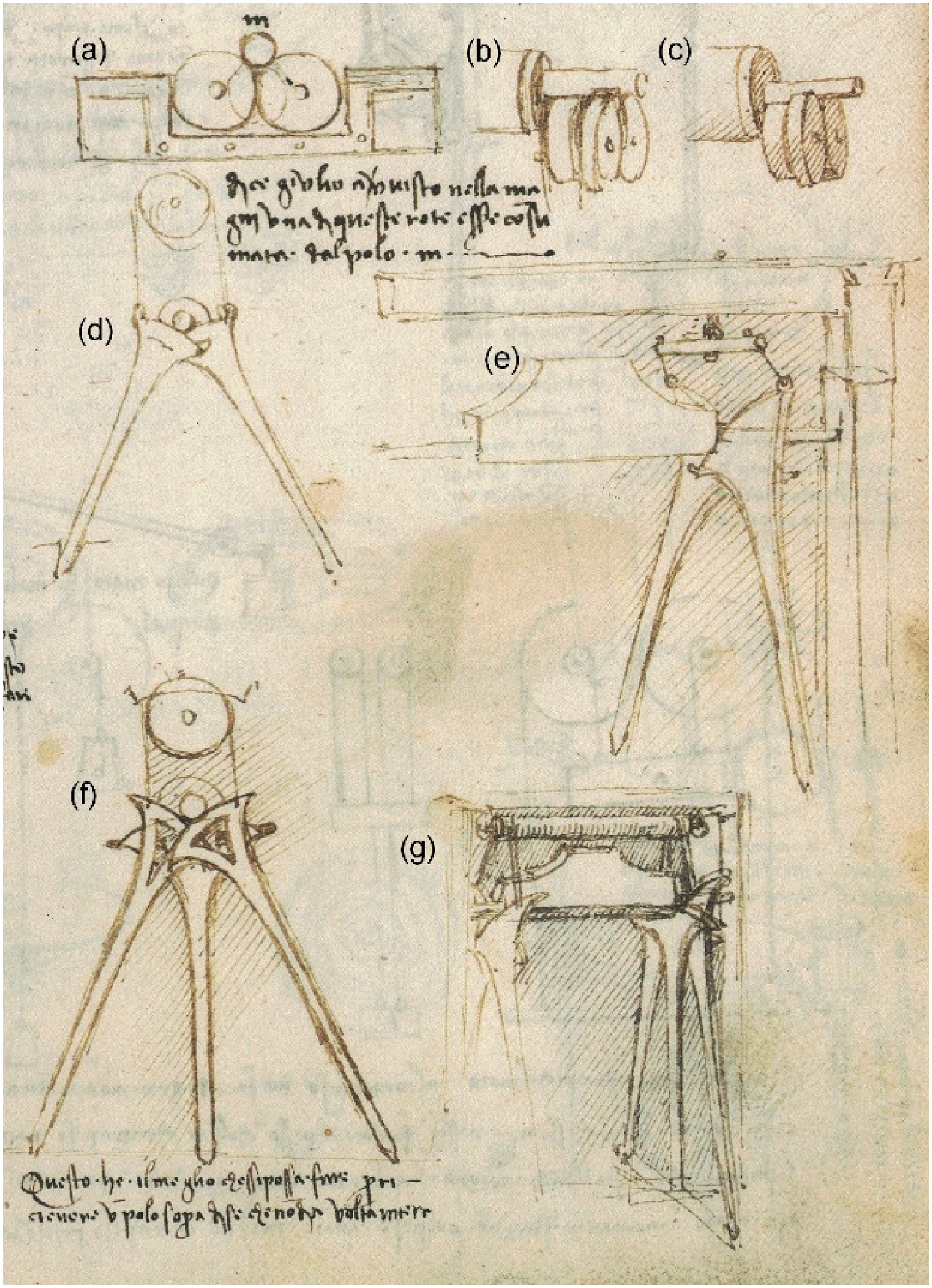
Disc and sector bearings, Madrid I f. 12v, 1493–1497 (Biblioteca Nacional, Madrid; image reversed).
Figure 2 (from MS B f. 70v, 1487–1490) shows disc bearings supporting a bell; each of the two shafts protruding from the yoke is supported by twin discs. The text reads ‘make the pivots of the bell low so that they are almost at the middle of the bell, so the part beneath the pivot does not weigh more than 10 pounds more than that above it. And a young child will (be able to) ring it’. iv
Bell supported on disc bearings, MS B f. 70v, 1487–1490 (Bibliothèque de l’Institut de France, Paris).
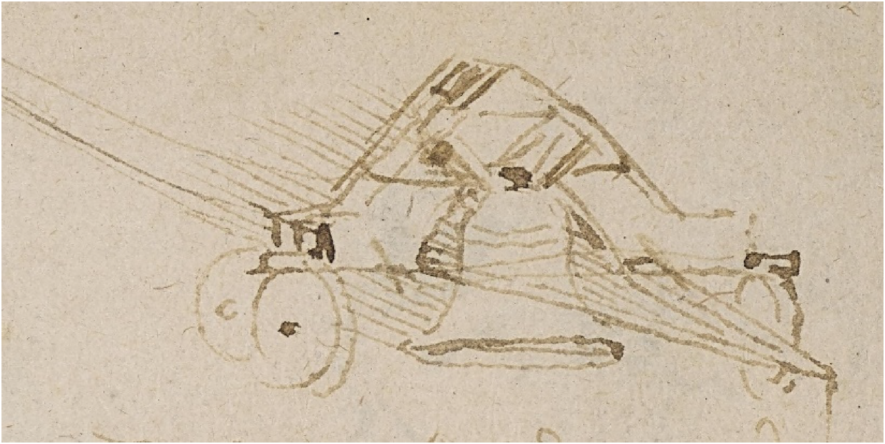
Leonardo also sketched designs for carts using discs to achieve low friction at the wheel bearings. The concept sketch in Figure 3(a) from MS B f. 99r (1487–1490) has been annotated ‘carro facile’ in another hand (and not in Leonardo's characteristic ‘mirror writing’); Leonardo's own note beneath it reads ‘this is a cart that is very easy to pull, but make the axles thin’ v . A later, much more refined design for a cart with more realistically proportioned wheels and a single axle supported on disc bearings (Figure 3(c), from Madrid I f. 69v, 1493–1497) includes a detail drawing of the bearing arrangement, while another (CA f. 1049r, 1498–1499), has the comment ‘here the wheel turns together with its axle because they are fixed together, and the weight is above the wheels a and n, placed at b and at c’. vi
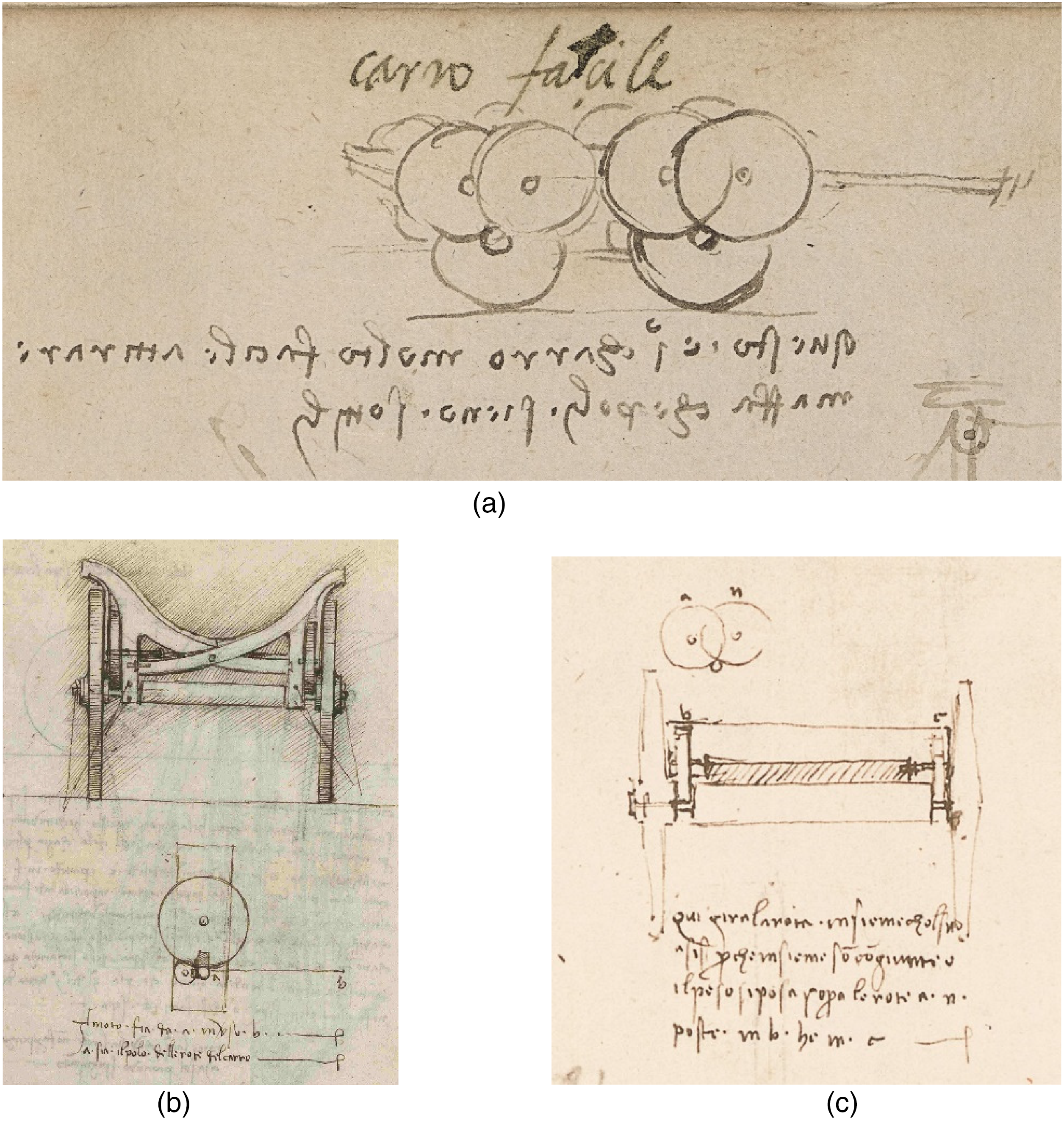
Examples of disc bearings for carts (a) MS B f. 99r, 1487–1490 (Bibliothèque de l’Institut de France, Paris); (b) Madrid I f. 69v, 1493–1497 (Biblioteca Nacional, Madrid; image reversed) ; (c) CA f. 1049r, 1498–1499 (Biblioteca Ambrosiana, Milan; image reversed).
Figure 4 shows further applications of the principle of the disc bearing, but in these examples, he uses short or long rollers to provide a low-friction lateral support for a vertical shaft; further information is lacking about the possible use of these radial bearing devices.
Radial bearings with rollers on fixed axles, Madrid I f. 101r, 1493–97 (Biblioteca Nacional, Madrid).
If instead of rotating continuously, the shaft supported by the discs oscillates through an arc, as in the swinging of a bell, then the discs will also make only partial rotations and can be replaced by sectors of discs with the distal ends supported by simple rocking pivots. These sectors can then have a much greater radius of curvature, giving a correspondingly reduced frictional torque on the shaft. In Figure 1(d) to (g) Leonardo sketches four versions of such sector bearings: with either two sectors (d and e) or three (f and g). At the bottom left beneath (f), he writes ‘this is the best that can be done to support a shaft that does not make complete revolutions’ vii .
These relatively simple types of disc and sector bearings supporting horizontal shafts formed the basis for numerous and in some cases increasingly fanciful developments of the same concepts. In order to adapt the idea of the disc bearing to support a downward load on a vertical rotating shaft, Leonardo replaced the discs with cones, leading to the designs in Figure 5. In the top sketch, the conically-ended vertical shaft is supported by contact with two cones running on horizontal axles. This design could in principle operate as a low friction thrust bearing, involving pure rolling motion at the interfaces between the conical end of the shaft and the mating conical surfaces. Its mechanical principle is the same as that of a set of mitre bevel gears. Some means (not shown in this sketch) would also be needed, however, to prevent the vertical shaft from moving perpendicularly to the plane of the diagram.
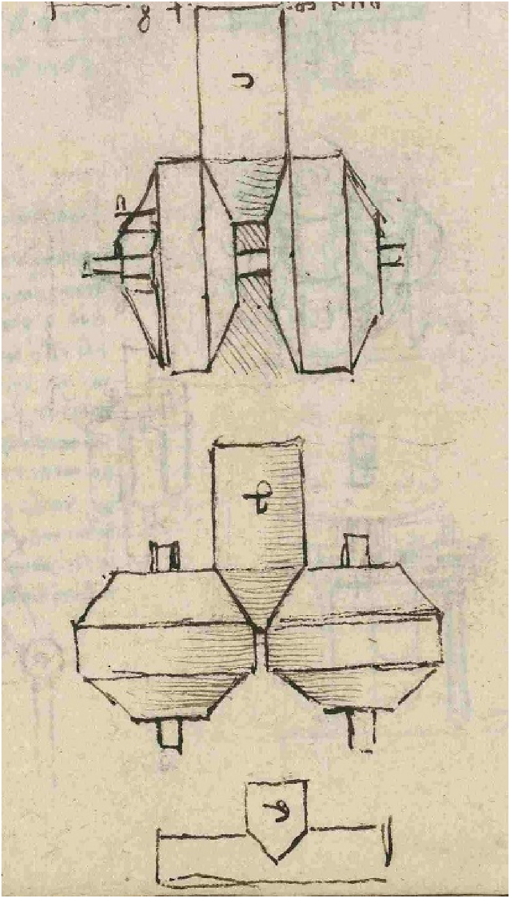
Pivot thrust bearings using cones, and (bottom) a plain bearing for comparison, Madrid I f. 101v, 1493–1497 (Biblioteca Nacional, Madrid).
The design shown in the middle sketch (labelled d by Leonardo) has two supporting cones rotating about vertical axes. While apparently similar in principle to the design above, it suffers from a fundamental defect. It would only be possible for the surface speeds of the conical shaft-end and the supporting cones to match to give pure rolling motion at a single horizontal plane; above or below this level, the surfaces would move with different speeds and would therefore slide at their interface. The friction in the system would inevitably be high, and this design could not possibly function as a successful bearing. Leonardo acknowledges this, noting beside the sketch ‘pivot d is close to pivot e (i.e., the plain thrust bearing shown below it) in poor performance (literally ‘sadness’) because it is not in proportion to its supports. Thus when this shaft gives a complete turn, it will give a complete turn to its supports. Where they are equal to the shaft in thickness they will make contact without friction, and where the thickness of the shaft is more different from that of the supports, it will make contact with more friction. And that friction will be almost equal to that of pivot e’. viii
Elsewhere, Leonardo sketched other arrangements of conical rotors to support the end-thrust on a rotating shaft, often accompanied by comments that show that he fully understood the constraints on the design that were needed to achieve pure rolling contact. For example, the design in Figure 6(a) (from Madrid I f. 102v) which uses additional rotors to support the lateral forces carries the note ‘the ratio between the width of the shaft ab and the width of each wheel am and bn, will be the number of whole turns of the shaft when the wheels give one full turn. But ensure that this is a whole number because if it were not, it would not do exactly the same. However, as far as motion is concerned, the contact lines exchange completely, for every degree of motion, and nowhere along the contact line is there friction.’ ix In the same manuscript (Madrid I f. 113v), we find the design of Figure 6(b) which uses both plain bushes and rotors to resist the lateral thrust, where Leonardo explicitly stipulates that ‘the part in contact between the shaft m and the rotors at x and z touches at a point’ x , thus ensuring pure rolling motion and avoiding the friction that would ensue if the contact were extended along a line. In Figure 6(c), however, (from CA f. 1081v, 1499–1500) Leonardo discusses only the extent to which the vertical load on the shaft causes a lateral force on the supporting cones; it is not apparent from the diagram that it does not suffer from the same defect as the middle design in Figure 5.
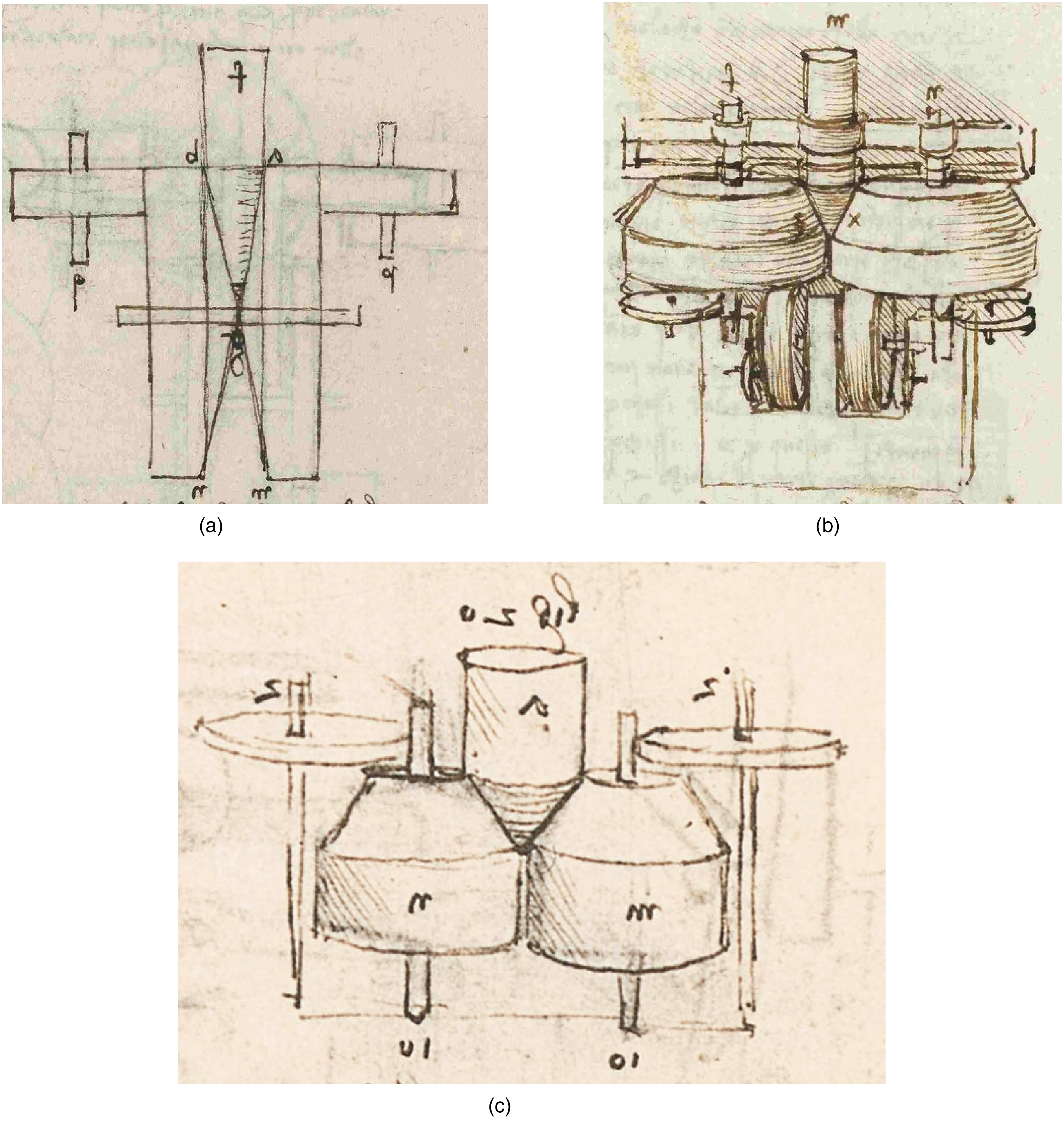
Cone thrust bearings (a) Madrid I f. 102v, 1493–1497 (Biblioteca Nacional, Madrid); (b) Madrid I f. 113v, 1493–1497 (Biblioteca Nacional); (c), CA f. 1081v, 1499–1500 (Biblioteca Ambrosiana, Milan).
Having satisfied himself that the frictional torque on an axle could be reduced substantially by supporting it on discs, it was natural for Leonardo to extend the concept by supporting the axles of those discs on other discs to form a stack or cascade of disc bearings. He sketched developments of this idea on many occasions. Figures 7(a) and (b) show two examples of two-stage stacks drawn at about the same time; the note on Figure 7(a) reads ‘method for easy pivots’ xi , but Leonardo has then crossed out the diagram with the word ‘false’ (falsa). Both these diagrams appear on manuscript pages that also show detailed sketches of water-wheels: while it is possible that Leonardo intended these bearings to be used in that context, there is no other hint that that was the case. The third sketch (Figure 7(c)) is essentially identical and appears a little later in Codex Madrid I, but with no relevant note. Beneath Figure 7(d) (from MS I f. 113v, 1497), Leonardo discussed how the vertical load on the upper axle becomes distributed between the four lower axles. Some 10 years later, he made a detailed calculation of the frictional torque on a roller supported by a stack of two disc bearings (Figure 7(e) from CA f. 961r, 1508; see 1 ).
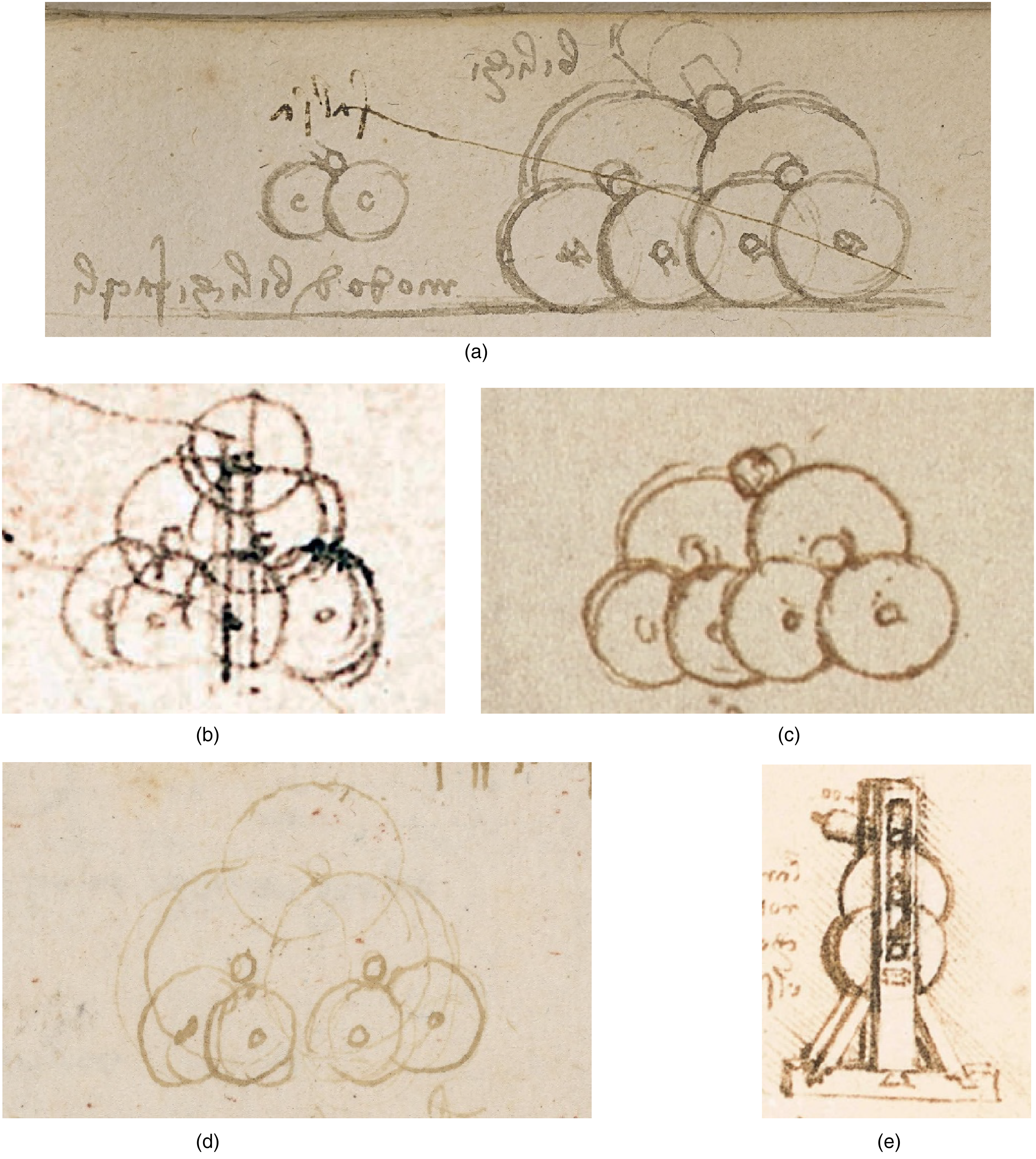
Examples of stacks of disc bearings (a), MS B f. 33v, 1487–90 (Bibliothèque de l’Institut de France, Paris); (b), CA f. 557v, 1487–1490 (Biblioteca Ambrosiana, Milan); (c), Madrid I f. 48v, 1493–1497 (Biblioteca Nacional, Madrid); (d), MS I f. 113v, 1497 (= Cahier 2 f. 65v, Bibliothèque de l’Institut de France, Paris); (e), CA f. 961r, 1508 (Biblioteca Ambrosiana, Milan).
Reti 17 has suggested that Leonardo marked the sketch in Figure 7(a) as ‘false’ because the axles would wear, but this diagram is essentially the same as others that he drew significantly later (e.g., Figure 7(c) and (d)). It seems more likely that he realized that the design as drawn would not be useful for rolling over a flat surface as implied by the sketch, and that in order to serve, for example, as bearings for a cart it needed to be inverted (as seen in the sketch of Figure 3(a)).
Leonardo enthusiastically explored the potential for reducing friction by cascading ever-increasing numbers of disc bearings one above the other: Figure 8(a) from Madrid I f. 102r (1493–1497) shows front and side views of an axle supported on a stack of discs, with the note ‘this invention is in the first class of perfection in ease (of motion) because it can be extended to infinity. Each wheel that is added below adds a degree of ease of motion, and this increase can continue to infinity. Therefore by this means the ease can be increased to infinity.’ xii The two versions depicted differ: the frontal view shows five supporting discs with the same diameter, whereas in the side view, there are seven supporting discs, whose diameters increase progressively from top to bottom. This gradation in diameter would prevent the axle of each disc interfering with the rim of the disc above it, an issue noted explicitly by Leonardo in the diagram shown in Figure 8(b) of a slightly later date. Here he uses 11 supporting discs, and writes ‘this rule (i.e., method) will make circular motion of such duration that it will appear marvellous and un-natural, because it will make a lot of movement after being driven. And if the weight m is dropped from such a height that the wheel turns 30 or more times, and then remains free like a spinning top. And to avoid a loud noise this stone should fall on a straw. And making each wheel larger than the next, successively one after the other is only necessary so that the edge of each wheel does not impede the axle of the next’ xiii . Elsewhere in the same notebook (Figure 8(c)) he sketches discs inclined at an angle to the vertical so that instead of the alternating pairs and single discs of Figure 8(a) and (b), he can produce a vertical stack with single discs; however, this design would suffer from the same problem of unmatched surface velocities as that discussed above for conical thrust bearings.
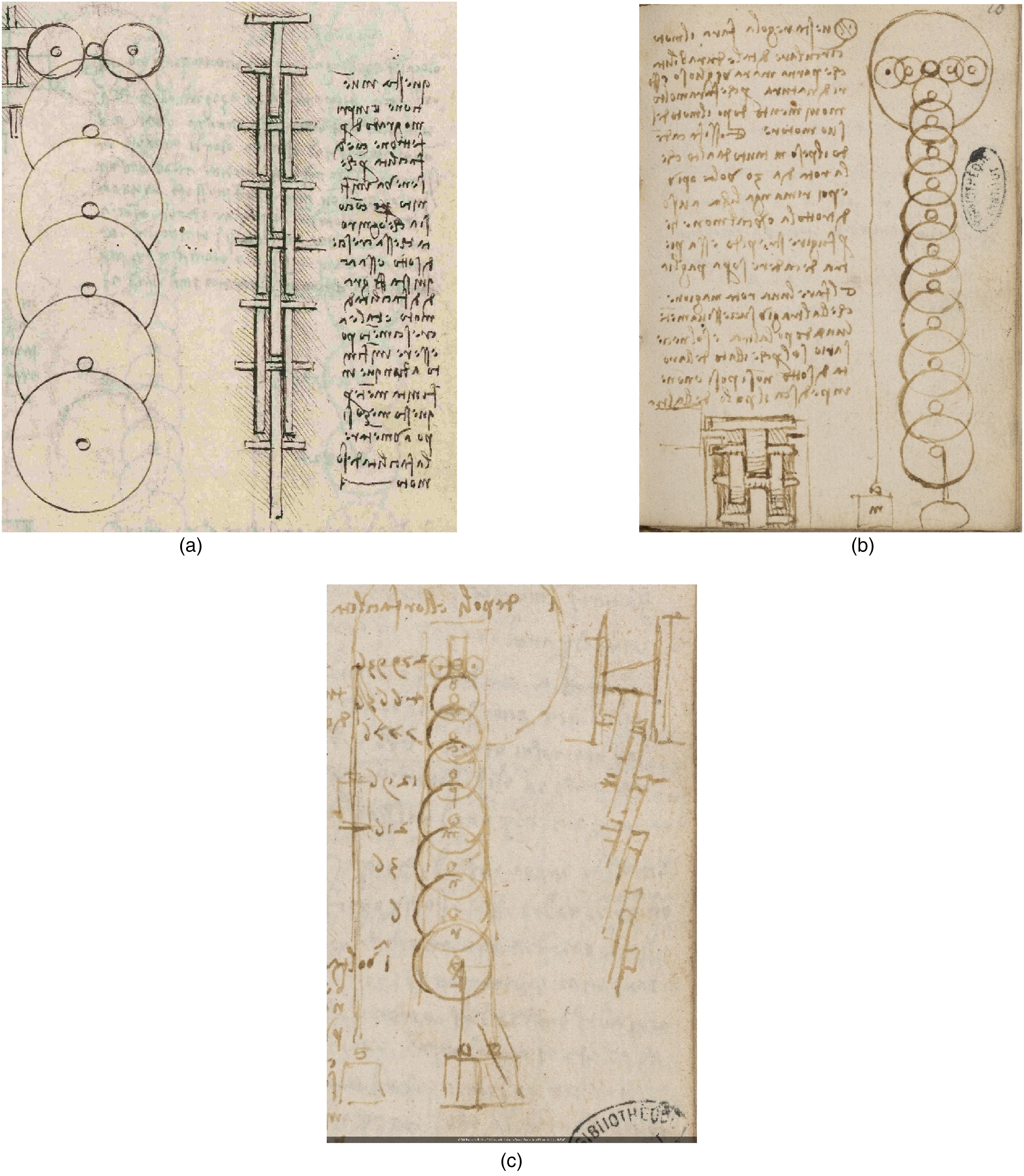
Examples of stacks of disc bearings: (a) Madrid I f. 102r, 1493–97 (Biblioteca Nacional, Madrid); (b), MS I f. 58r, 1497 (= Cahier 2 f. 10r, Bibliothèque de l’Institut de France, Paris) (c), MS I f. 114r, 1497 (= Cahier 2 f. 66r, Bibliothèque de l’Institut de France, Paris).
Leonardo extended his designs of sector bearings in the same way, and we find several sketches of stacks of multiple sectors, again with notes marvelling at the reductions in friction they might achieve. Figure 9(a) shows an example. He shows two stacks: of discs to support a continuously rotating shaft, and of sectors for an oscillating shaft, as used for a bell. The text reads ‘these 2 methods are expedient and to be used by practitioners. One is made by the motion of the same path, and the other by motion that goes and returns and each is rotational. The first moving wheel has its lengths of 72 to one, that is 72 half-inches to one half-inch, because the axle is one inch wide and the lever 3 braccia xiv ; and if the lever which pulls the bell is 3 braccia and at its end is one pound of force, it will move at the bottom, at the counter-lever f, 26,873,280 pounds’ xv . Not uncommonly, Leonardo makes small mistakes in his arithmetic (in fact, 724 = 26,873,856), but his calculation of the mechanical advantage of the stack of sectors still leads to an impressive result; he continues the note xvi by suggesting that with this system, a dog could be trained to ring a heavy bell by pulling on a thin string.
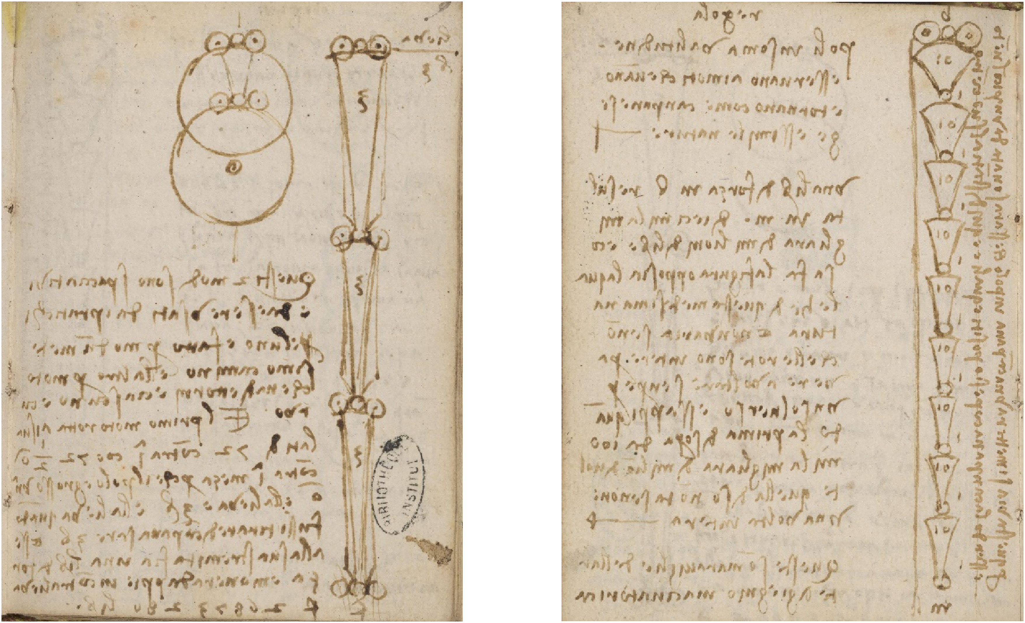
Examples of stacks of sector bearings (a), MS I f. 57r, 1497 (= Cahier 2 f. 9r, Bibliothèque de l’Institut de France, Paris); (b) MS I f. 57v, 1497 (= Cahier 2 f. 9v, Bibliothèque de l’Institut de France, Paris).
On the verso of the same page (Figure 9(b)), Leonardo draws an even longer sequence of stacked sectors, each with a lever ratio of 10:1, and remarks alongside the sketch ‘in this way a bell can be placed on an axle so that it can be rung by a small wind, if the bell has equal opposing weights equidistant from its centre.’ xvii The text continues: ‘Pivots at their greatest value; they are useful for reciprocating motions such as bells, and saws and things of a similar nature. One pound of force at b results in ten thousand thousand million pounds at m … These are marvels of the art of inventive genius’ xviii .
Rolling element bearings
Leonardo remarked on the benefits of separating moving surfaces by freely rolling elements on several occasions. Beside the sketch in Figure 10(a) for example, he writes ‘no completely plane weight can be more easily pulled from its position than one which rests on perfect spheres which lie on a perfect plane’ xix . In Figure 10(b) (also from Madrid I) he notes ‘a weight that rests on rollers, wheels or balls is easier to move than one that is supported by its axles’. xx More general comments on friction, including the benefits of separating sliding surfaces with rolling elements, can be found in Leonardo's contemporary notes in Codex Forster II (f. 132r, 1495–97, V&A Museum, London xxi ): ‘everything however thin that is placed between objects that rub together lightens the difficulty of friction. Observe the friction of great weights which make rubbing movements … the larger the wheel that is interposed, the easier this movement becomes, and so conversely less easy when it is thinner, as with a thin greasiness; and so tiny grains like millet make it better and easier, and even more so balls of wood or rollers, i.e., cylindrical wheels; and as these rollers are made larger, so the movements become easier’. xxii
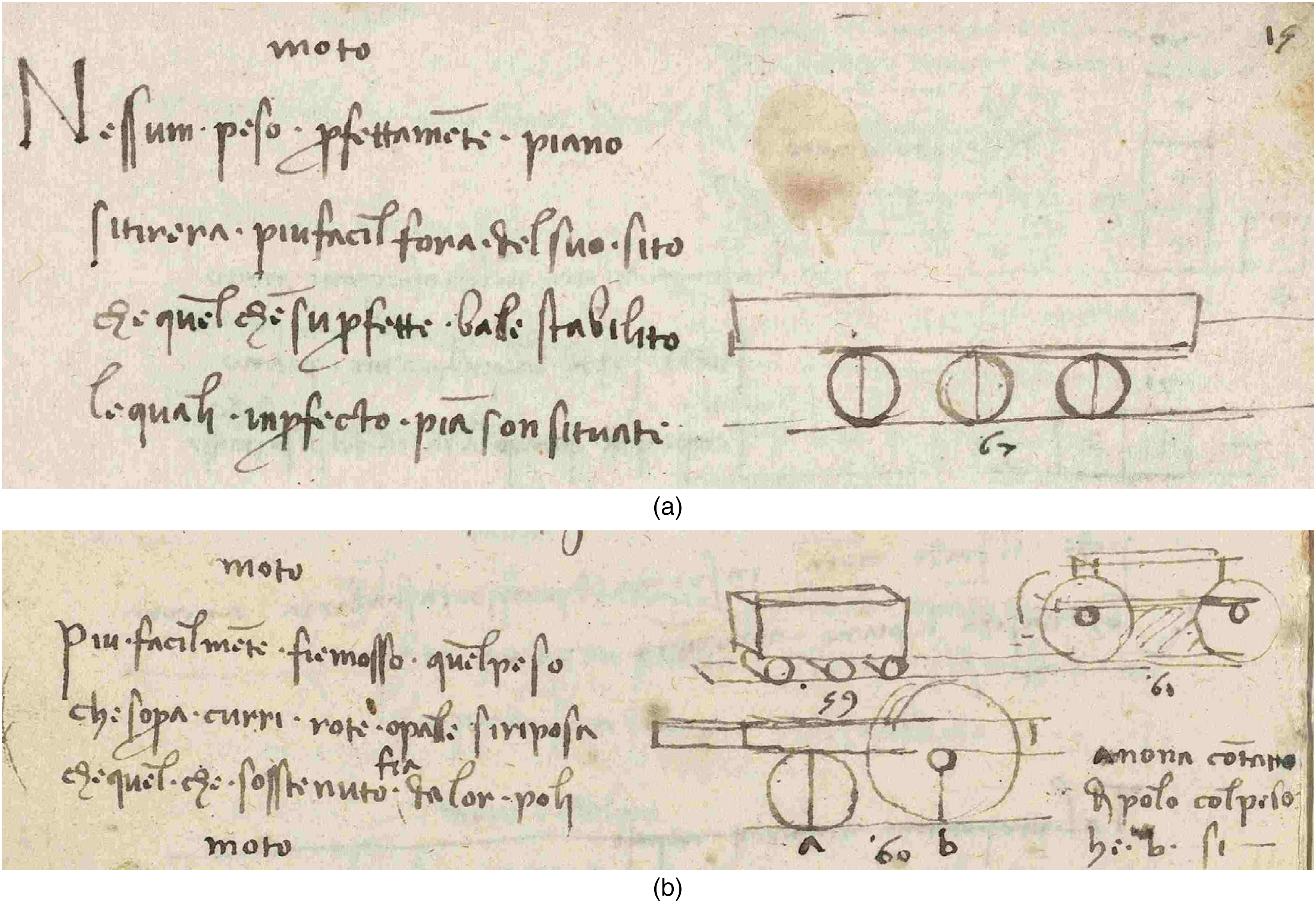
Illustrations of the benefits of rolling elements (a), Madrid I f. 176v, 1493–1497 (Biblioteca Nacional, Madrid; image reversed) (b), Madrid f. 178r, 1493–1497 (Biblioteca Nacional; image reversed).
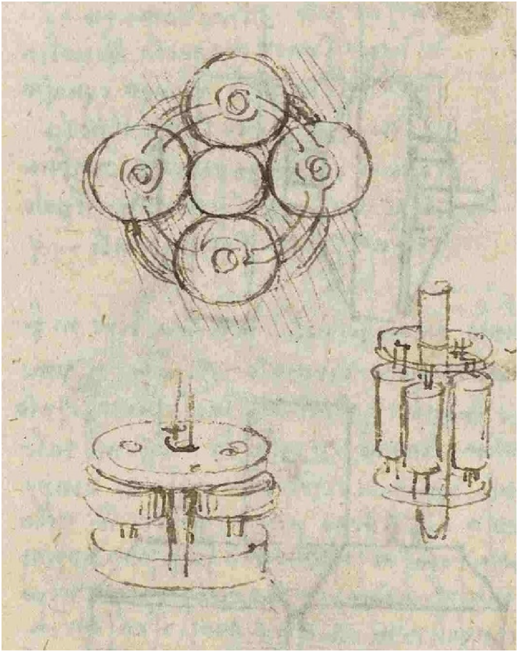
Leonardo sketched several designs of true rolling-element bearings that used these principles. Nearly all were thrust bearings, intended to accommodate a downward load on a vertical shaft. The pivot bearings depicted in Figure 11 are examples, with a conically ended shaft supported by either three or four balls, or by three conical rollers. The sketch with four balls in MS I (Figure 11(b)) is not accompanied by any relevant text, but by the designs with three balls in Madrid I (Figure 11(a)) the text reads ‘the 3 balls under the shaft are better than 4, because by necessity they must always touch and be equally moved by the shaft. With 4 there would be the danger that one of them would not touch and so would not be moved, and would be expected to cause friction’. xxiii The design using three conical rollers with the same geometry as the end of the shaft (Figure 11(c)) was, however, preferable to all of the others, because it would lead to less wear: ‘ … the best that one can find … This arrangement is strong and durable, more than the one supported by 3 balls, because where there is less contact there will be more wear, and as the balls touch at a point they will inevitably wear quickly’. xxiv
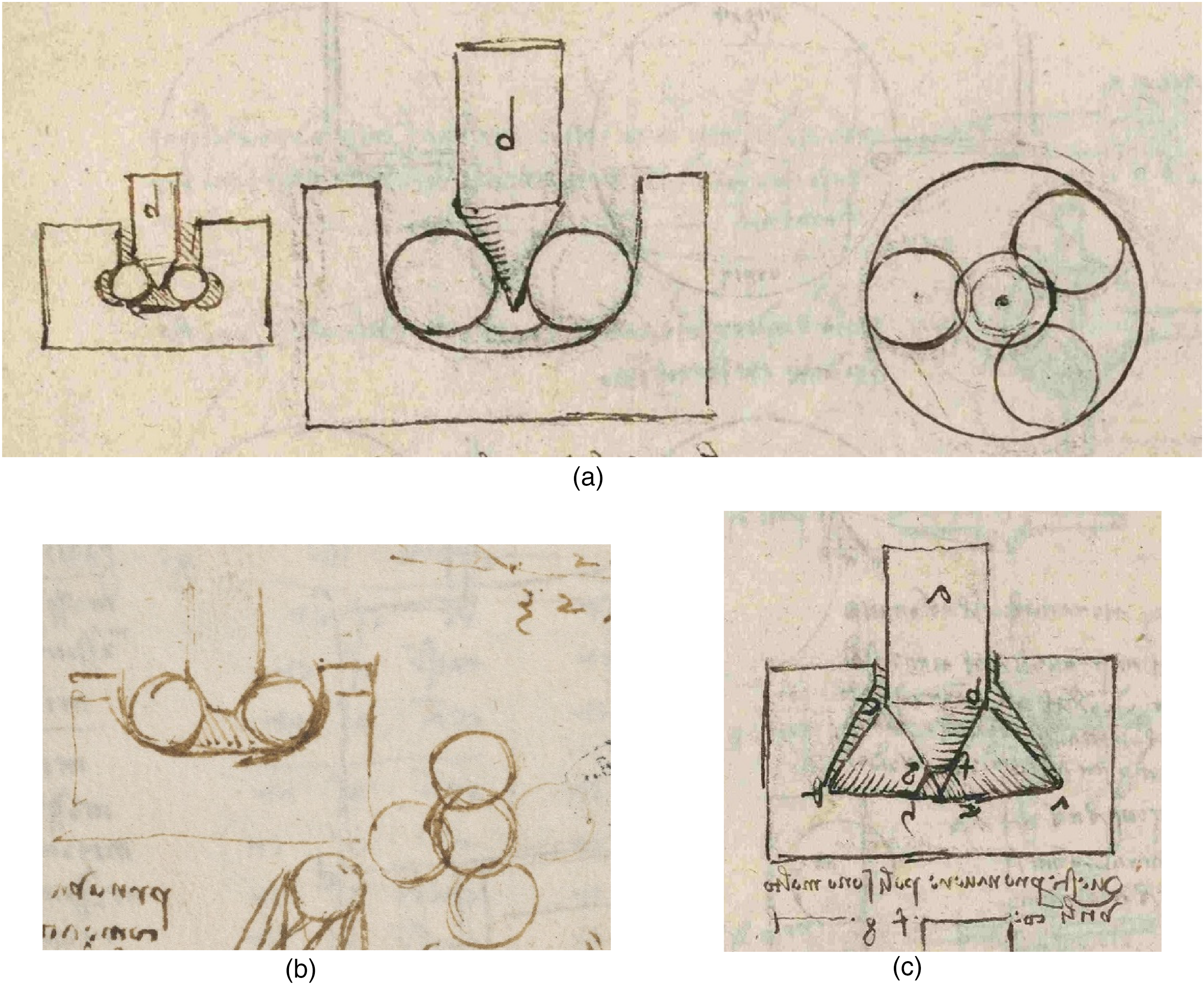
Pivot bearings with rolling elements (a), Madrid I f. 101v, 1493–1497 (Biblioteca Nacional, Madrid) (b), MS I f. 38r, 1497–1499 (Bibliothèque de l’Institut de France, Paris); (c), Madrid I f. 101v, 1493–1497 (Biblioteca Nacional, Madrid).
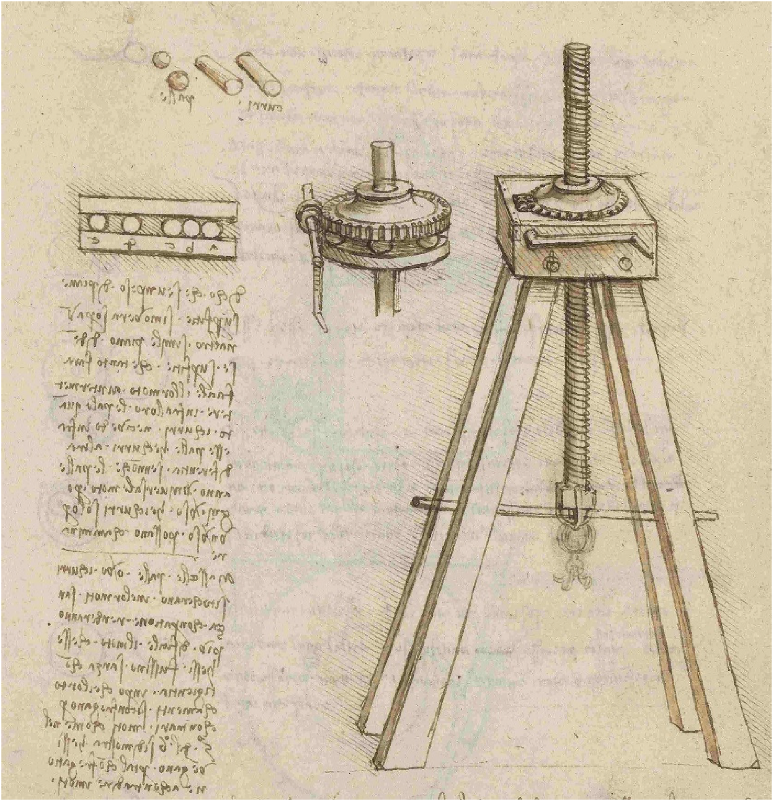
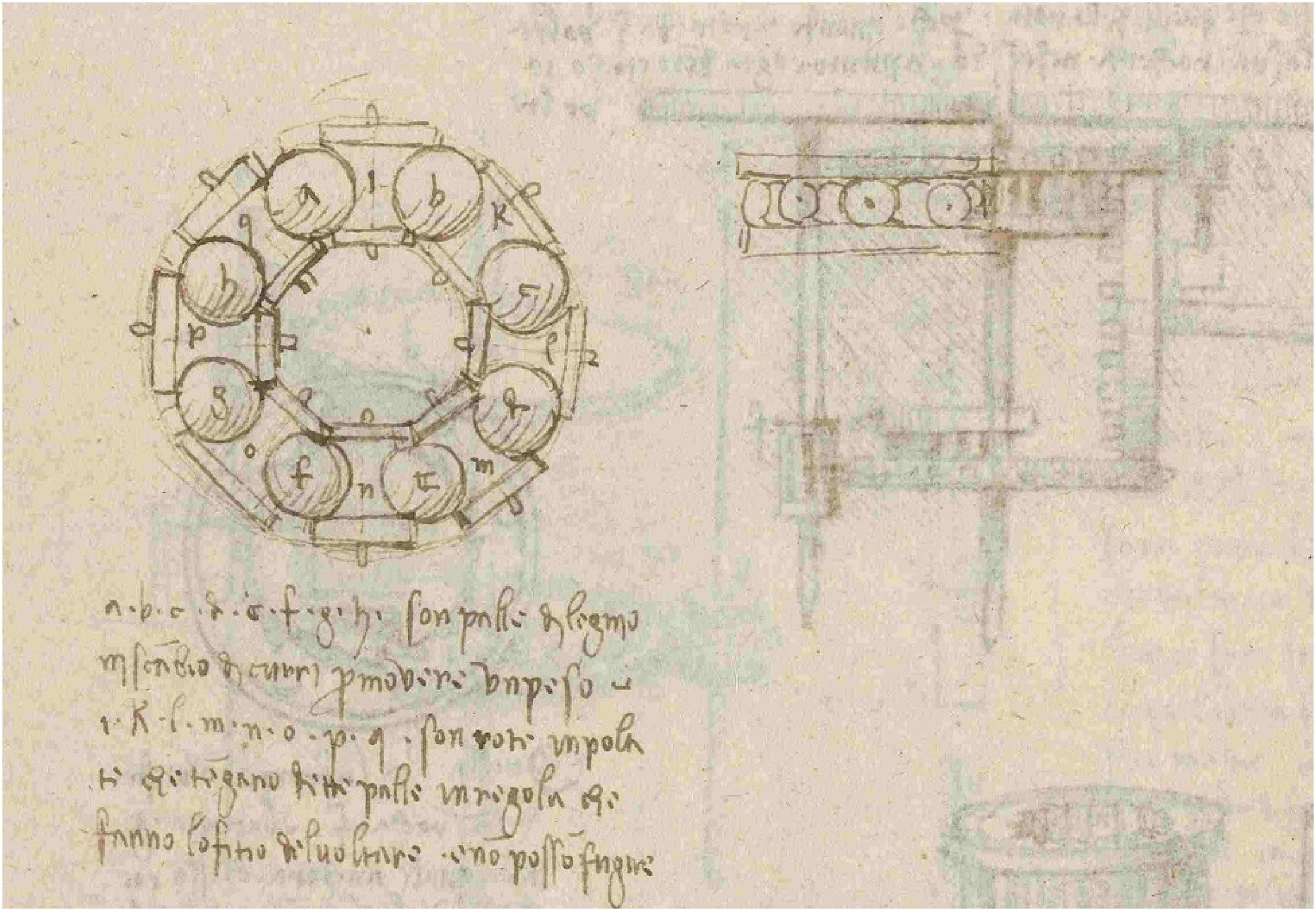
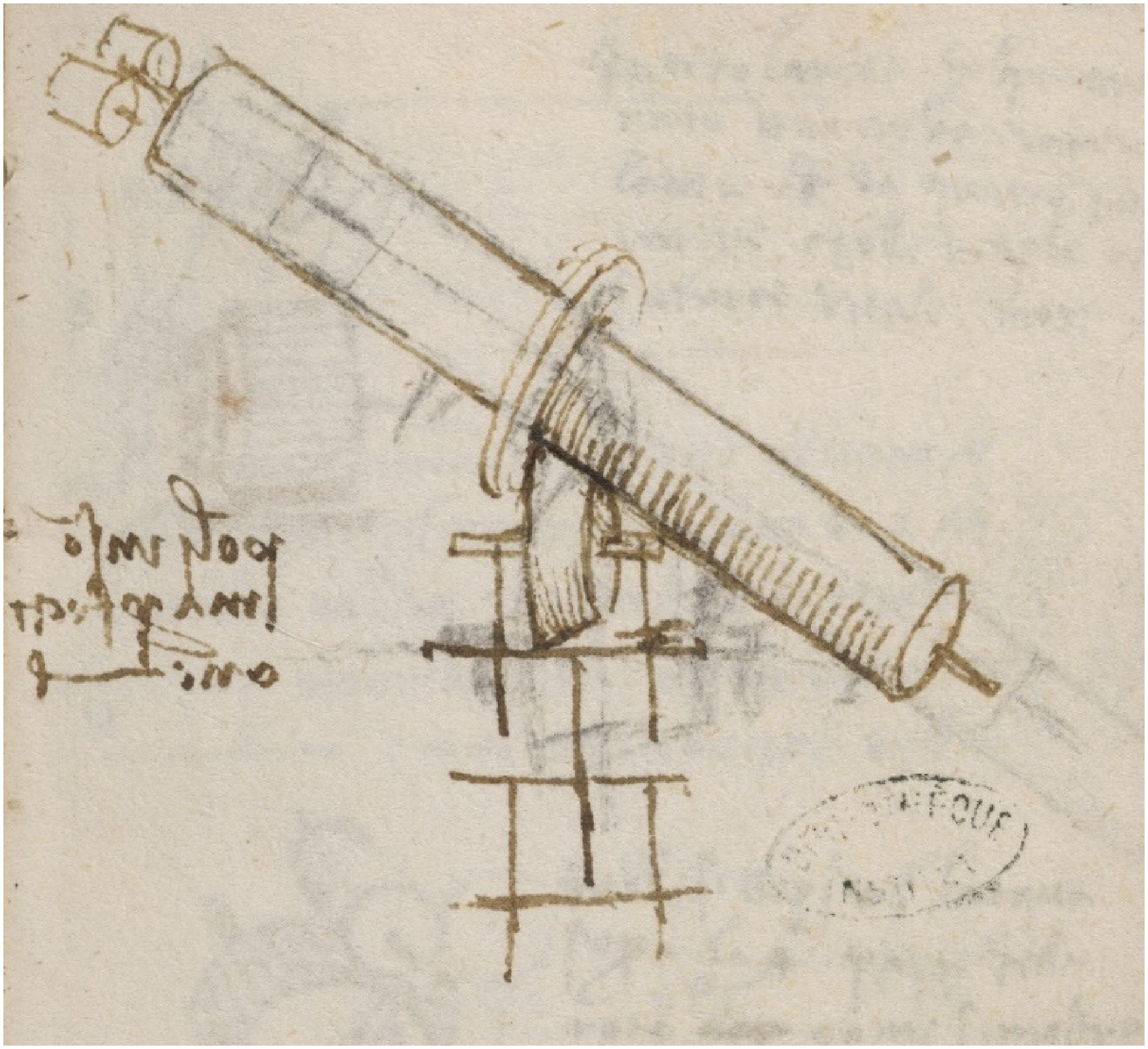
Figure 12 shows a remarkably modern-looking design for a screw-operated hoist with a very large mechanical advantage, in which a crank handle drives a worm gear that lifts the hoisting shaft via a gear wheel with an internal screw thread. The downward force on the gear wheel is carried by a ring of balls also shown in the two detail sketches. Leonardo is keen to avoid friction between neighbouring balls, writing: ‘I say that if a weight with a plane surface is moved over another similar plane hard surface, the motion will be just as easy whether balls or rollers are placed between them. I see no difference between balls and rollers except that balls can move in all directions, whereas rollers can only travel in one direction. But if the balls or the rollers touch each other in their movement, they will undoubtedly make it more difficult than if there was no contact, since their touching is by contrary motions … and that friction acts to impede their motion’. xxv The elevation drawing shows examples of rolling elements both separated and in contact. On this page Leonardo does not suggest how the balls or rollers might be kept apart, but also in the same notebook (Figure 13) he draws two views of a thrust bearing containing eight balls with rotors separating them, writing: ‘ a b c d e f g h are balls of wood instead of rollers, to move a weight. i k l m n o p q are wheels on axles, that keep the balls in place so that they turn and cannot escape’. xxvi The separators are quite complex devices, each drawn as a rotor with a central axle supported by two discs. From the elevation sketch, it is clear that the upper and lower bearing plates must have plane surfaces: the balls do not run in indented tracks, but as Leonardo comments, are prevented from escaping only by the presence of the intervening rotors.
Screw hoist with ball thrust bearing, Madrid I f. 26r, 1493–1497 (Biblioteca Nacional, Madrid).
Ball thrust bearing with interposed rotors, Madrid I f. 20v, 1493–1497 (Biblioteca Nacional, Madrid; image reversed).
There is only a single, isolated example of Leonardo using freely rolling rollers in a radial bearing (in CA f. 1017v). This sketch is unusually imprecise, apparently showing six rollers (although as drawn, not all are of the same diameter) surrounding a vertical shaft; it comes from a sheet containing several design details for a polishing machine that has been dated to ca. 1513. 20
Discussion
Leonardo's notebooks provide a record of his careful observations of the world around him, both natural and man-made, as well as of his own original thoughts and ideas on a very diverse range of topics. In the field of engineering, separating Leonardo's descriptions of then-current practice from his own innovative concepts, and identifying the truly original elements of his studies, is not easy, not least because the sheer quantity of the notes and sketches available to us far surpasses those of any other engineer of the period. It is easy to be misled by the number, quality, and level of detail of Leonardo's sketches and notes into assuming that what is described must be a novel design by Leonardo, rather than something he has seen and wishes to record and classify. This has led in the past to exaggerated claims about the originality of Leonardo's inventions in several fields, including tribology.
Leonardo worked in an environment rich in the European technology of the time. Numerous drawings of mechanical devices by Italian engineers of the Quattrocento have survived in the form of ‘machine books’, manuscript collections whose authorship is in many cases unclear. These often include depictions of military engineering for both offensive and defensive purposes. Some of these manuscripts are clearly copied from other sources, including from the influential work of Mariano Jacopo (Taccola) (1382 – c. 1453), Francesco di Giorgio Martini (1439−1501) and Buonaccorso Ghiberti (1451–1516). The work of Francesco di Giorgio, in particular, was widely copied but was itself partially derived from earlier sources.21,22 Leonardo knew Francesco personally and possessed a manuscript copy of his work that still exists xxvii . There was also a fertile technological culture in southern Germany, recorded in contemporary manuscripts, with considerable overlap in content with the Italian manuscripts.
Disc and sector bearings
Early suggestions (e.g., by Canestrini 11 ) that Leonardo had invented the type of twin-disc bearing shown in Figure 1(a) were refuted by the rediscovery of the Madrid Codices, in which Leonardo himself indicated that the design shown in Figure 1(a), with two discs supporting the shaft, was already in use in Germany. The note in darker ink beneath that diagram reads ‘Giulio says that in Germany he has seen one of these wheels to be worn by the axle m’ xxviii . Giulio (known as tedesco = German) was an assistant who had entered Leonardo's service in 1493, and was one of several German craftsmen who worked with him xxix . However, while acknowledging that the design with two discs was indeed already known in Germany, Reti16,17 suggested that Leonardo had improved upon this arrangement by introducing a third disc vertically beneath the axle (as in sketches b and c in Figure 1), or alternatively, if the motion of the axle was oscillatory as for a swinging bell, by replacing the complete discs by sectors of discs. This view was also been taken by Pedretti. 23 xxx Both Reti and Pedretti suggested that the 3-sector bell bearing depicted by Jacob Leupold in a review of machine designs in 1724 25 (Figure 14), and a very similar design still in use today for the great bell (la Mutte) in the cathedral of Metz, France, had been derived from an original design by Leonardo (Figure 15). This places a sector vertically beneath the axle, and uses two horizontal sectors to accommodate any sideways thrust; cords attached to the horizontal sectors ensure that as one moves down, the other moves up, a feature also present in the two-sector bearings shown in Figure 1(d) and (e). The sketch in Figure 15 shows four possible configurations for the cords, as well as counterweights hanging from the distal ends of the horizontal sectors.
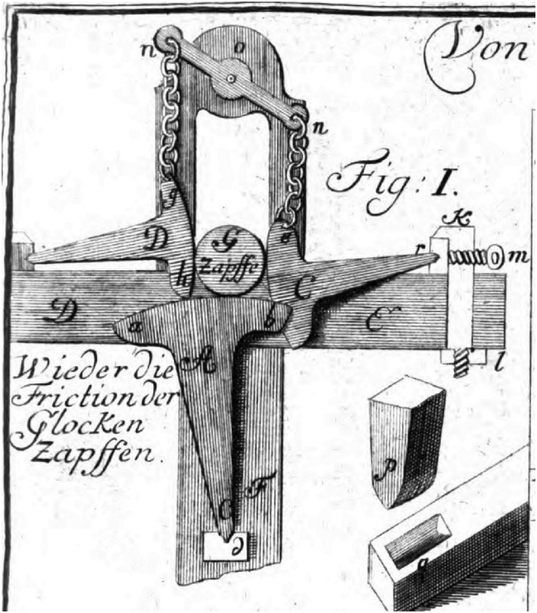
Sector bell bearing from Jacob Leupold, 1724. 25
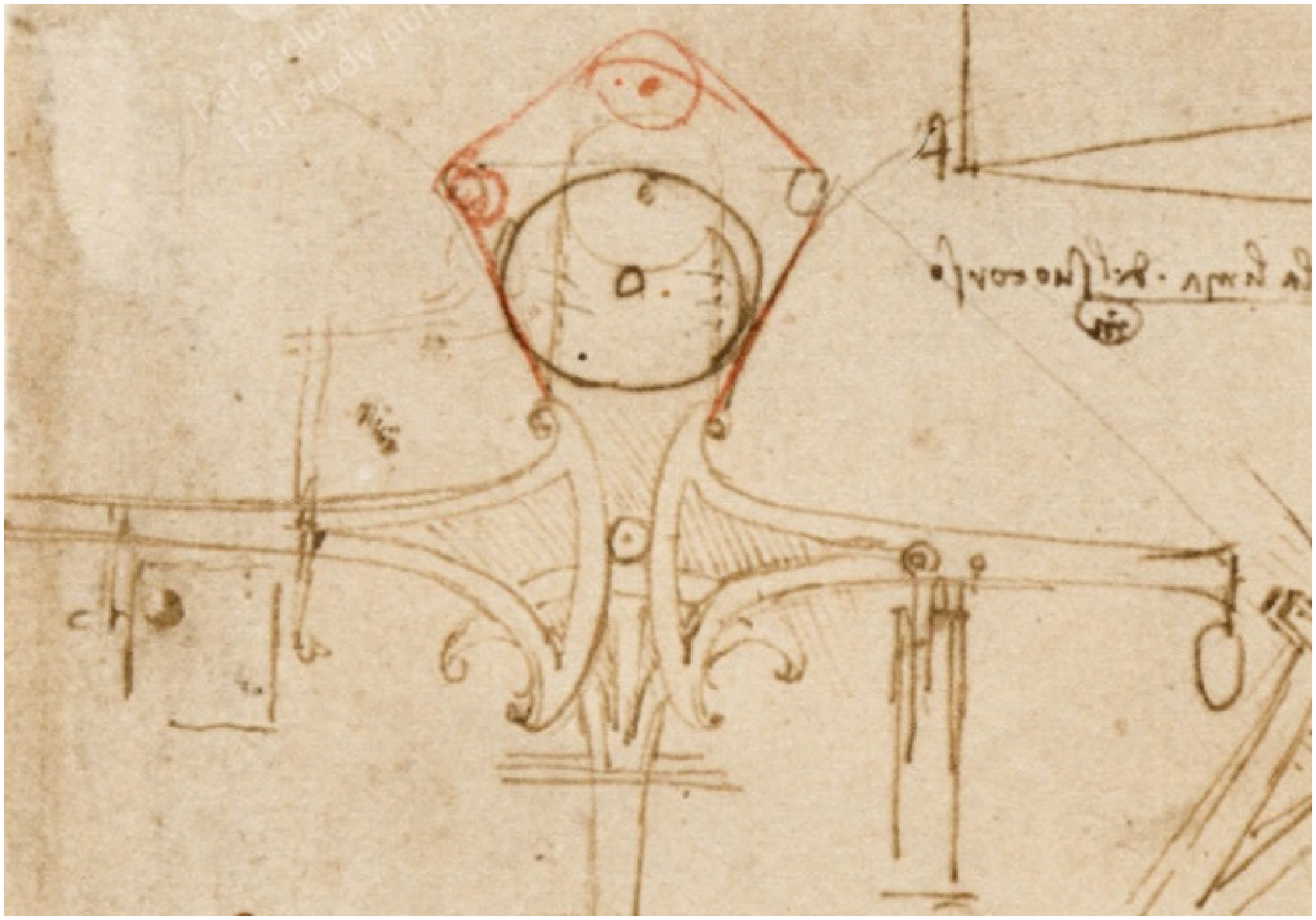
Sector bell bearing from CA f. 1086r, 1499–1500 (Biblioteca Ambrosiana, Milan).
Brioist 26 and Roegel 27 have traced the history of the bell suspensions used for the Metz bell, and shown that while the current bell originated in the sixteenth century (replacing an earlier bell from 1480), the bearings similar to that in Figure 14 were installed only in 1813, some 300 years after Leonardo's sketches. Earlier bearings for the Metz bell had used two obliquely inclined sectors, similar to the designs shown in Figure 1(d) and (e) but without the cords.
Direct evidence that the use of disc or sector bearings in fact pre-dated Leonardo's drawings is hard to find, but there is good circumstantial evidence for this view. Brioist 26 has proposed that twin-sector bearings had been installed for the Metz bell as early as 1480, basing his view on historical records. Rathgen 28 drew attention to the use of three-sector bearings to support the oldest bell (Hosanna) in the cathedral of Freiburg, Germany which dates from 1258 xxxi ; based on contemporary accounts, he also suggested that sector bearings were employed in the giant trebuchets used in the siege of Vellexon, Burgundy in 1409–1410. Traces of the distinctive cut-outs needed to accommodate sector bearings for bells are still to be found in the wooden bell-frames of numerous churches in southern Germany xxxii ; a well-researched example is at St Martin's, Landshut, Bavaria, where the timbers have been accurately dated to 1500, although the date when the sector bearings themselves were installed cannot be precisely inferred. 30
Figure 16 shows detailed drawings of disc and sector bearings for bells from a manuscript written in Bavarian German in 1524 xxxiii . The author, Christof Seselschreiber, succeeded his artist father Gilg in managing a bronze foundry at Mühlau near Innsbruck, and worked as a master gun-maker as well as a bell-founder; a single bell cast by him in 1519 survives in Salzburg xxxiv . While the content of much of this manuscript is clearly copied from others, no earlier source has been suggested for the detailed notes on bell-founding, and the drawings in Figure 16 appear to be original to Seselschreiber; these three diagrams with the captions ‘to hang bells on shields/plates’ and ‘on discs’ are the only illustrations of bell bearings in the manuscript. In these alternative configurations, there is either a complete disc or a shield-shaped plate forming a sector of a disc, supporting the axle, together with either two discs or two sectors to resist the sideways thrust. It is striking that, unlike Leonardo's sketches, these drawings show the detail of the associated ironwork, even down to the fixing bolts, and also include features on the horizontal sectors to restrict their range of movement: they evidently represent practical installations rather than mere concepts. The colour in the depiction of the discs in Figure 16(a) suggests that they were of a different material from that of the other components (which were presumably iron or steel), but since the same yellowish wash is used elsewhere in the manuscript for both wooden and bronze objects it is impossible to draw further conclusions about the materials used here. In the use of a sector to support the shaft together with two discs to provide the lateral constraint (Figure 16(b)), Seselschreiber provides a variant that is absent from Leonardo's sketches.
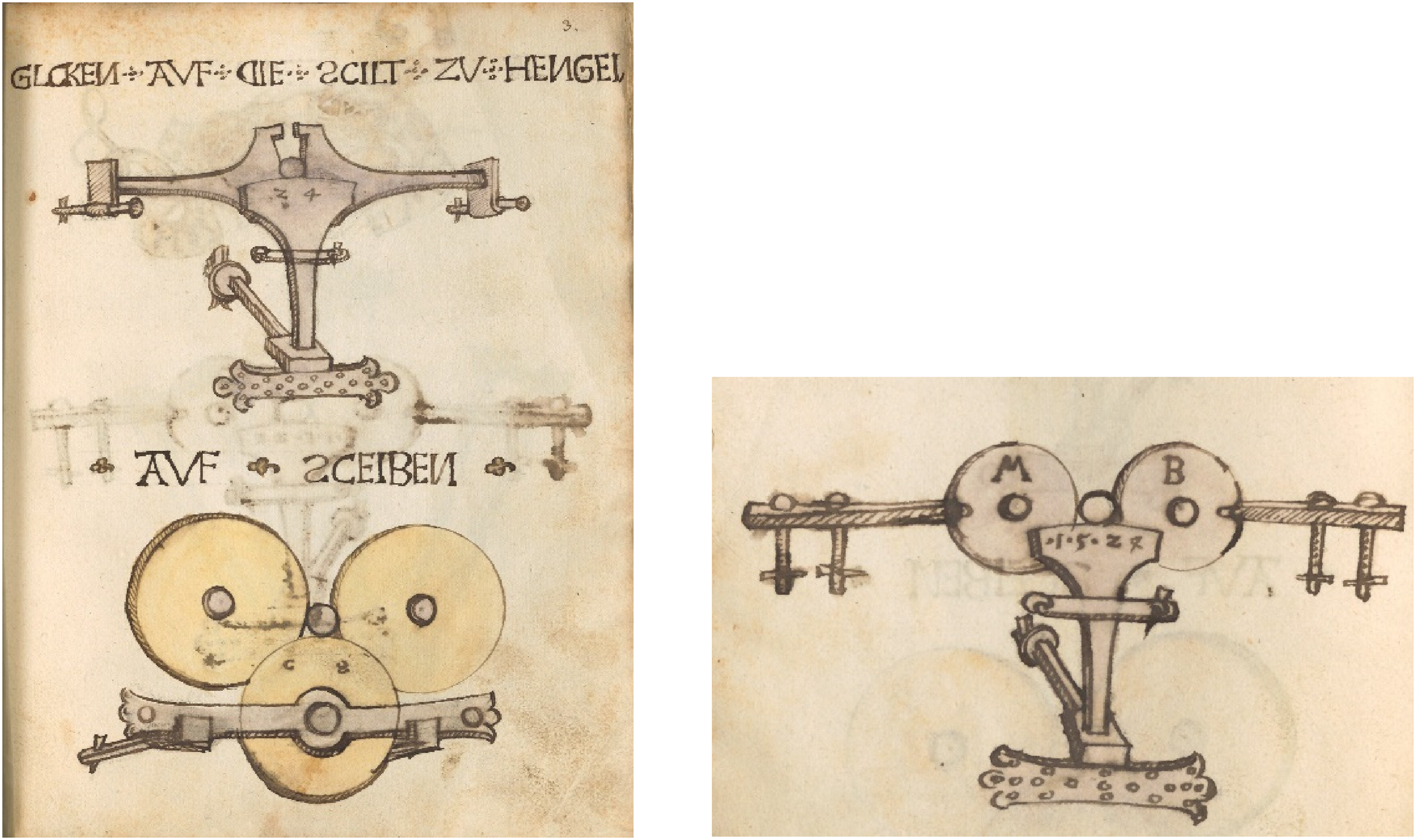
Drawings of disc and sector bell bearings, from Christof Seselschreiber, MS Cgm 973, 1524 (Bayerische Staatsbibliothek, Munich) (a) f. 3r, (b) f. 3v.
It is notable that among the methods of hanging bells illustrated in Biringuccio's Pirotechnia from 1540 32 (Figure 17) there are no examples at all of disc or sector bearings; they show very strong similarities to designs recorded by Francesco di Giorgio in 1460–1480 xxxv , dating from significantly before Leonardo's work. Biringuccio states that ‘in every bell tower and other place where there are bells’ the bells are supported by horizontal iron bars which are ‘round so that they may turn easily when they are held by two steel rings or in two metal grooves or on glass pillows’. Clearly, a diverse range of bearing systems was then in use for bells in northern Italy, which these sources suggest had not changed much for many decades; one would have expected that if the use of disc or sector bearings had been at all common by 1539, Biringuccio who travelled widely and based his descriptions of bell technology on personal experience and observation, would have recorded them in his comprehensive treatise.
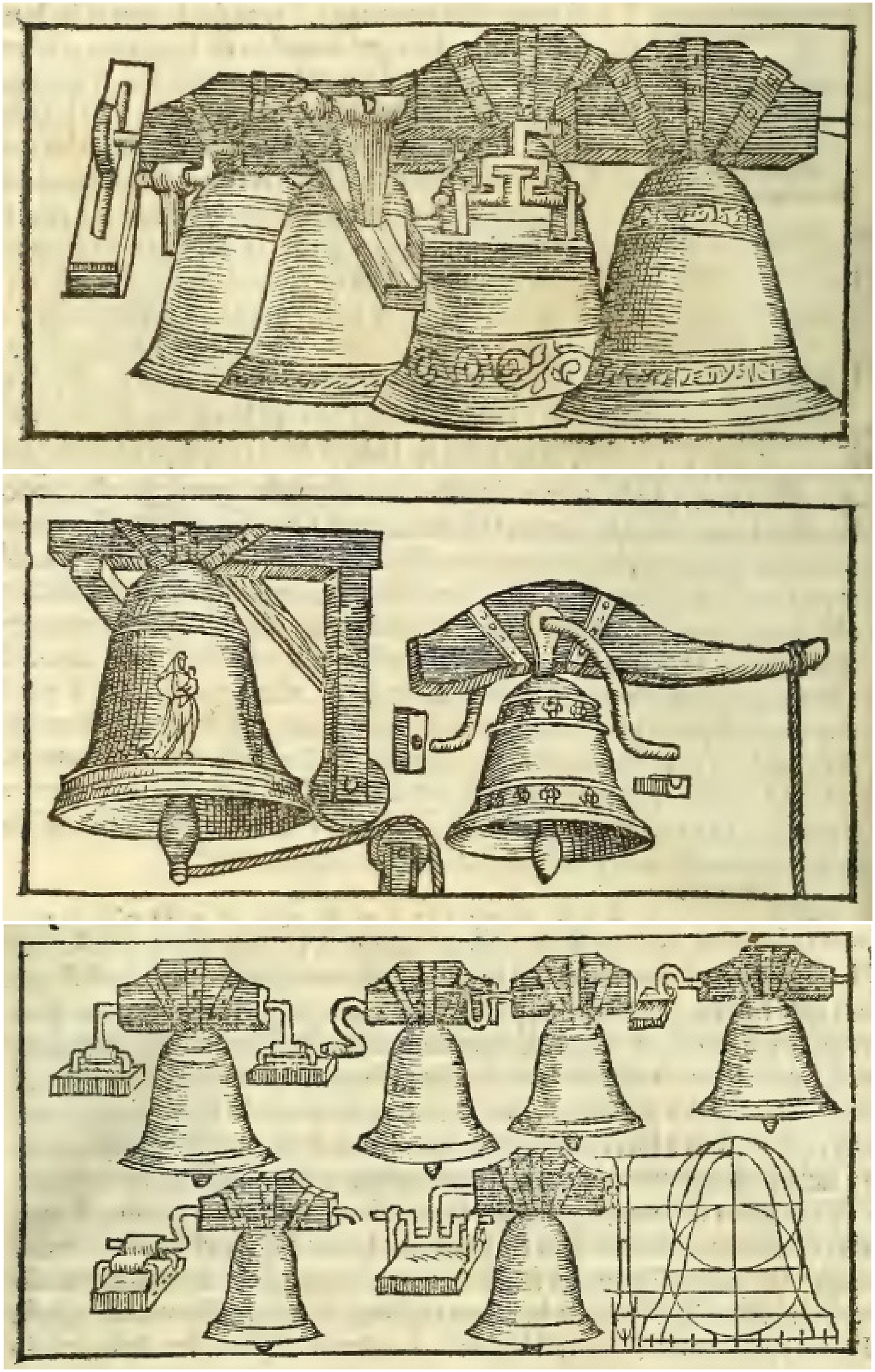
Illustrations of bell bearings from the Pirotechnia of Vanoccio Biringuccio, 1540. 32
All the above evidence points to these distinctive types of bearing having first been developed north of the Alps and remaining in use there for many years. While Leonardo's studies extended the concept underlying disc and sector bearings, he did not originate it.
What does appear to be original to Leonardo, however, is the idea of stacking multiple disc or sector bearings to achieve even greater reductions in frictional torque, as shown in Figures 7 to 9. These sketches show designs of increasing impracticality as the number of the stages is increased: at what point Leonardo's ideas move from the practical to the fanciful is never clear, but his fascination with the theoretical power of these machines to achieve phenomenal gearing ratios is evident. He refers to ‘marvels of the art of inventive genius’. But his suggestion that in this way a very small force generated by a child or a dog, or a gust of wind, could be used to ring a large bell, for example, completely ignores the inertia of the system, or the fact that a restoring moment would be needed to ensure that the bell returned to its vertical position.
The impracticality of a machine design was never an obstacle to Leonardo recording it, as is also clear from the drawings of the thrust bearings in Figures 5 and 6. These too are original, but as noted above, while some might have worked perfectly satisfactorily, others suffer from the fundamental defect of kinematic incompatibility, as Leonardo himself acknowledged in at least one case. These defective designs have been reproduced without comment by previous authors (e.g.,16,19), and even used as the basis for a model, the construction of which would have instantly revealed the problem in its operation. 33
Leonardo's notebooks depict a very large number of mechanical devices, some of which were copied from existing designs, while others are original to him. Apart from their use for bells and cart axles, there are very few instances of disc, cone or sector bearings being shown in practical applications. One further example of a thought experiment rather than a realistic machine is shown in Figure 18; here a cone supports an inclined rotating cylinder, possibly representing an Archimedean screw in a hydraulic perpetual motion machine. The cone rolls against the surface of the cylinder (with the problem of kinematic incompatibility unremarked by Leonardo), while the axis of the cone is supported on a stack of disc bearings, shown schematically. Leonardo notes his opinion of this design beside the sketch: ‘bearings of supreme perfection’ xxxvi .
Cone and stack of disc bearings supporting an inclined rotating cylinder, from MS I f. 21r, 1497–99 (Bibliothèque de l’Institut de France, Paris).
Rolling element bearings
While Leonardo's notebooks contain sketches of disc bearings as early as 1487–1490 (in MS B), the first notes on the reduction of friction by the use of freely rolling elements appear somewhat later, in Madrid I (1493–1497). The designs shown in Figures 12 and 13 have been used by many writers to justify the statement that Leonardo invented the ‘ball bearing’. This claim deserves critical study. These bearings, like those of Figure 11, are thrust bearings (which carry an axial load) rather than the radial ball bearings with which they are usually compared. There is no representation of a radial ball bearing to be found anywhere in Leonardo's work, but several sketches of rolling-element thrust bearings.
There is certainly good evidence of the use of rollers within thrust bearings in northern Italy before the time of Leonardo. An example is provided by the images in Figure 19 of a twin-screw hoist for lifting heavy columns that uses roller thrust bearings to reduce the friction on the nuts. This design belongs to a collection of machine drawings that have in the past been ascribed to Francesco di Giorgio, but may well themselves have been copied by him 22 ; whatever the original source, it is clear that several versions of this drawing existed in the last quarter of the fifteenth century. Although the overall drawings are very similar, some differ in the detail of the roller bearings. Leonardo himself possessed a manuscript containing this drawing, and that version appears to show rollers that are free to roll beneath the nut (Figure 19(a)) xxxvii . Free rollers are very clearly depicted in a version dated to ca. 1480 (Figure 19(b)) and ascribed to Guidoccio Cozzarelli, 21 while some others from the last quarter of the fifteenth century show rollers rotating on fixed axles, either attached to the machine frame (Figure 19(c)) or, completely impractically, attached to the nuts as well (Figure 19(d)). Several examples of free rollers in thrust bearings in other applications can be found in late fifteenth century Italian machine books xxxviii , although they are absent from the somewhat earlier work of Taccola.
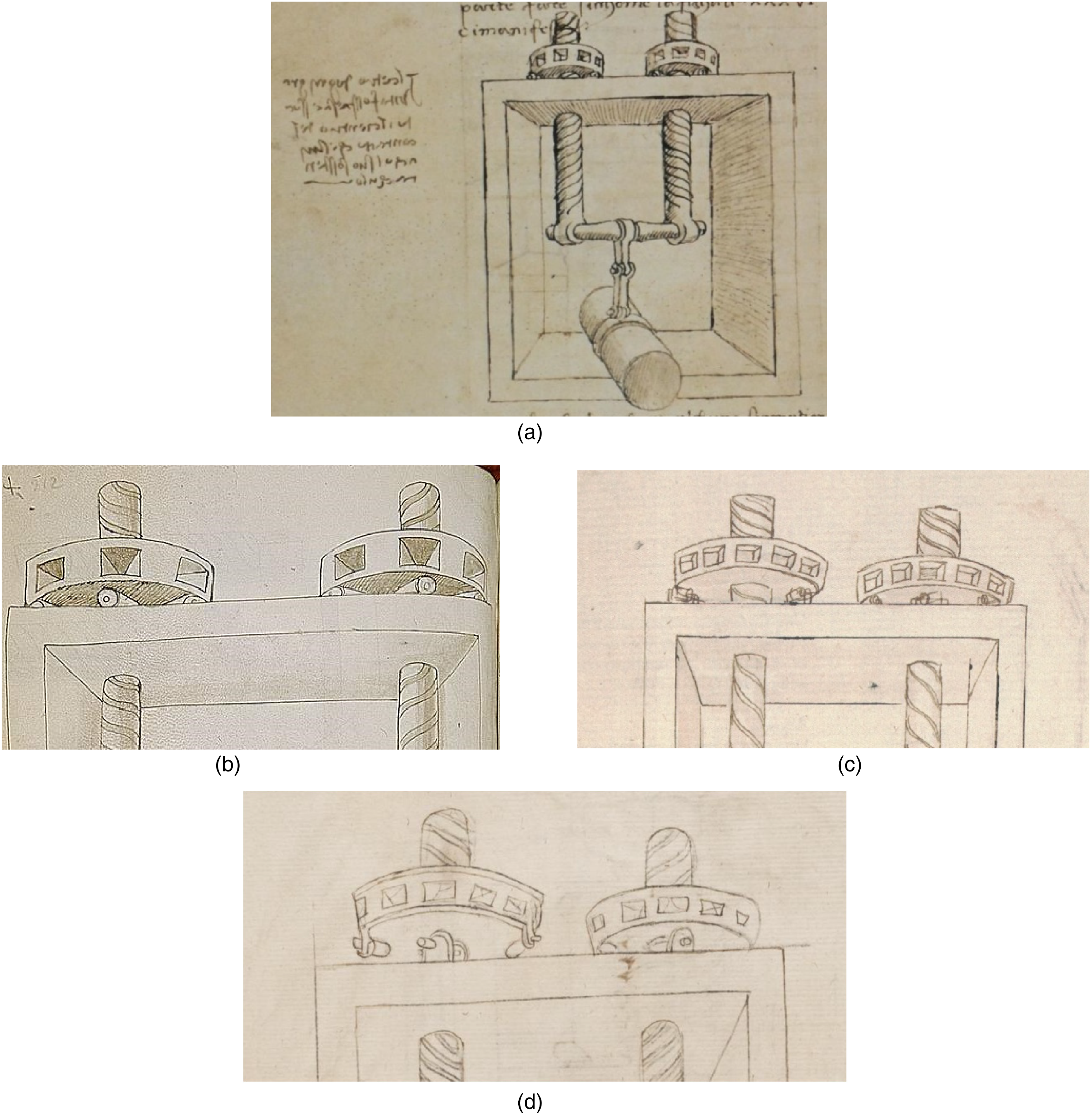
Twin-screw hoist (a) Ashburnham 361 (MS 282) f. 44v, 1480–1503 (Biblioteca Medicea Laurenziana, Florence) (b) detail from MS Palat.767, ca. 1480 (Biblioteca Nazionale, Florence); (c) detail from MS S.IV.5 f. 69v (Biblioteca Comunale degli Intronati, Siena). (d) detail from MS Dresd.Ob.13 f. 88v (SLUB, Sächsische Landesbibliothek-Staats-und Universitätsbibliothek, Dresden)
Leonardo's original contribution in the designs of the thrust bearings shown in Figures 11 to 13 lies in the use of balls as the rolling elements. When in Madrid I (f. 26r) he comments on the use of balls ‘instead of rollers’ it is quite likely that he is acknowledging the common use of rollers in other designs, and he correctly identifies the benefits of balls. However, his designs for ball thrust bearings (Figures 12 and 13) do suffer from important defects. Instead of running in grooves which would lead to more extended contact patches, reducing the stress on the balls and the mating surfaces as well as holding them within the bearing, the balls shown by Leonardo run between flat plates. In the design of Figure 12 the balls would be retained within the bearing by the surrounding stationary body of the hoist, but in Figure 13 Leonardo adds a set of interposed rotors, both to retain the balls and to prevent them from rubbing against each other. The function of these rotors in separating the balls has been compared with that of the ‘cage’ that is commonly used for the same purpose in modern axial and radial ball bearings.2,16,19,24 However, Leonardo's design is complex and suffers from the same defect as his design for the thrust bearing shown in the middle sketch of Figure 5. While it would be possible to achieve perfect rolling contact between a ball and a neighbouring rotor on the line of the pitch circle passing through the centres of all the balls, for larger or smaller distances from the centre of the bearing the surface speeds will be mis-matched and relative sliding will occur. This lack of kinematic compatibility, unremarked by Leonardo himself, has not been noted by previous commentators either. In fact, friction between neighbouring balls is not an important issue in ball bearings, and modern ‘full complement’ bearings, both axial and radial, function perfectly well without a cage and with neighbouring balls in contact.
Conclusions
Leonardo da Vinci's activities as an engineer are often overshadowed by his fame as an artist, but they were nevertheless remarkable. Most biographies fail to do justice to his evident knowledge and understanding of mechanical systems, and the ingenuity he showed in many areas of technology is often appreciated only by specialists in those topics. Tribology provides just one example. No near-contemporary of Leonardo comes close to providing the richness of detail in the design of bearing systems that is seen in his notes. Leonardo's descriptions of disc and sector bearings, while mostly derived from designs he had seen or heard about, are analytical and supplemented by comments that show deep insight. He extended pre-existing designs in novel ways: for example by replacing discs with cones, and by cascading stacks of bearing elements to achieve increasingly large reductions in friction. Although his use of free rollers as rolling elements in bearings had been anticipated by earlier practice, Leonardo showed remarkable inventiveness in using conical rollers in thrust bearings, and in his designs for axial ball bearings. However, he rarely discriminated between realistic designs that could be (and were, perhaps) implemented, and fanciful ideas that can never have been more than that. In his numerous designs of bearings, as in many other fields, Leonardo's imagination often exceeded the limits of practicality, and it is unclear whether any of them were ever realized by him or by others. His notebooks nevertheless provide a window into the workings of a unique mind.
Footnotes
Declaration of conflicting interests
The author declared no potential conflicts of interest with respect to the research, authorship, and/or publication of this article.
Funding
The author received no financial support for the research, authorship, and/or publication of this article.
Appendix A – Endnotes
i
Biblioteca Leonardiana: Archivio digitale di storia della tecnica e della scienza: www.leonardodigitale.com For Codex Madrid I see also leonardo.bne.es; and for Codex Atlanticus: codex-atlanticus.ambrosiana.it and Leonardo//thek@ at ![]()
iii
Translating Leonardo's technical writing into English understandable by modern tribologists and engineers is complicated by the lack of specialized mechanical terms in Leonardo's vocabulary, and the comparative richness of modern technical English. There are often several possible translations for a single word in the original: For example, the commonly-used word polo can mean ‘axis’, ‘axle’, ‘shaft’, ‘pivot’, ‘journal’ or even ‘bearing’, depending on context. Translations in this paper are by the author, aided in part by those of Reti, Venerella and MacCurdy.
iv
fa che i poli dello mozzo della campana sieno in modo bassi che battendo quasi al mezzo della campana, che la parte ch'è del polo in giù, non pesi più che 10 libbre più che quella dal polo in su. E soneralla uno putto
v
questo é un carro molto facile a tirare, ma fa ch’e poli sieno sottili
vi
qui gira la rota insieme col suo assis perché insieme son congiunte e il peso si posa sopra le rote a n poste in b e in c.
vii
questo è il meglio che ssi possa fare per recievere un polo sopra di sè che non dia volta intera
viii
Il polo d é vicino al polo e per tristitia, perché non é proportionato colli sua sostentaculi. Vedi che lla sua somma larghe[za] é ssimile a l'infima largheza de' sua sostentaculi. Onde quando tal polo darà una volta intera, elli darà volta intera ancora i sua sostentaculi. E dove sono per grosseza equali al polo, li fia contatto sanza confregatione, e dove la grosseza del polo é più disforme a cquella de' sostentaculi, li fia contato e ancora la sua magiore confregatione. E ttale confregatione fia quasi equale a cquella del polo e.
ix
Quella proportione che arà la grosseza del polo ab, colla largheza di ciasscuna rota am e bn, talle aranno il numero delle volte intere che darà il polo quando le dette rote daranno una volta intera. Ma ffa che 'l numero sia intero, che sse vi fussi rotti, non farebe così a punto. Benché, in quanto al movimento, le linie del contato si scanbiano interamente, in ogni grado di moto, e i' nesuna parte della lungheza di tale linie contattuali non n'acade confregatione.
x
la parte del contatto che ha il polo m, colle rote in x z, toca in punto.
xi
modo di bilichi facili
xii
questa inventione è in primo grado di perfettione, cioè di facilità, perché se ne va in infinito. conciosia che ogni rota che ss’ acrescie di sotto, essa acquista gradi di facilità di moto. e tale acrescimento pò essere in infinito. adunque infinitamente per questo mezo si pò aumentare la facilità d'eso moto
xiii
questa regola farà il moto circulare di tale durabilità che parrà meraviglioso e fori di natura, perché farà molto movimento dopo il moto del suo motore. e si fa cadendo il peso m tanto da alto, che la rota dia 30 volte o più, e poi rimanga libera a uso di trottola ovver calmone. e per fuggire strepido essa pietra de' cadere sopra paglia. e 'l fare l'una rota maggiore che l'altra, giù successivamente l'una dopo l'altra, è sol necessario, sol perché il lato della rota di sotto non si posi e non ne impedisca il polo dell'altra.
xiv
1 braccio = 12 once (inches)
xv
questi 2 modi sono spacciativi e da essere usati dai pratichi: e l'uno è fatto per mo[to] d'un medesimo cammino, e l'altro per moto che vadi e torni, e ciascuno è curvo. El primo moto rota ha i sua lati di 72 contra una, cioè 72 mezze once contra una mezza, perché il polo è grosso una oncia e la lieva è 3 braccia; e la lieva quando fussi tirare di campana, sare' 3 braccia, e se alla sua stremità fia una libbra di forza, e' moverà da piè, in contra lieva f, 26.873.280 libbre
xvi
on MS I f. 56v
xvii
per questa via si metterà una campana in polo, che sarà sonata da un piccol vento, essendo la campana co' pesi oppositi equali e equidistanti al suo centro
xviii
poli in somma valitudine, e servano ai moti che vanno e tornano, come campane, seghe e simile nature. Una libbra di forza in b resulta in m diecimila migliara di milioni di libbre….. . Queste son maraviglie dell'arte d'ingegno machinatorica
xix
nessun peso perfettamente piano si tirerà più facil fora del suo sito che quel ch'è 'n su perfette balle stabilito le quali in perfecto pian son situate
xx
più facilmente fie mosso quel peso che sopra curri, rote o palle si riposa, che quel che sosstenuto fia da' lor poli
xxi
Codex Forster II consists of two distinct notebooks bound together: Forster II1 of folios 1–63 from about 1495, and Forster II2 of folios 64–159 from about 1495–1497.
xxii
omnia e qualunque cosa per sottile ch'ella sia, la quale s’interponga in mezzo in fra le cose insieme confregate, alleggerisce la difficultà di tale confregazione. Vedi la confregazione de' gran pesi, i quali fanno i moti confregabili, come 'n la quarta del settimo dimostrai, che quanto maggiore rota s’interpone, tanto si rende tale moto più facile; e cosi de converso men facile, quanto il mezzo fia più sottile, come sarebbe alcuna sottile untuosità. E cosi crescendo, meglio e più facile la rendano i graniculi a uso di miglio, e più le palle del legno o curri, cioè rote cilindrali; e quanto tali curri fieno maggiori, tanto i movimenti fiano più facili.
xxiii
le 3 balle sotto il suo polo son meglio che torne 4, perché le 3 son con cierteza e per neciessità senpre toche, e equalmente mosse da tal polo. E Ile 4 vi sarebe pericolo, che una di loro non fussi toca, onde non sarebbe mosa e asspeterebe la conpagnia colla quale farebbe confregatione.
xxiv
… il più laldabile che fra questi poli trovar si possa, perché sono tre piramide, infra Iloro equali, e cosi sono equali alla piramide fatta dalla punta del polo. … E cosi sono forti e durabili, più che quella ch'è sostenuta dalle 3 balle, perché dov'è minore contatto, li fia magiore consumamento e Ile balle essendo toche in punto, è neciesario che presto si consumino.
xxv
dico che se un peso di piane superfitie si moverà sopra un altro simile piano di dense superfitie, che tanto farà facile il lor moto a intermettere infra lloro le pale quanto i curri. Né ci vedo infra esse palle e curri altra diferentia sennonché le palle hanno universale moto, per ogni verso, e i curri solo per un verso possano camminare. Ma sse lle palle, overo i curri, si tocherano in e lor moti, sanza conparatione renderanno più dificile il moto che sse essi fussino sanza contingientia. Inperoché i lor tocamenti si confregano per contrari moti, come nel 5° del 6° si dimostra, e ssi vengano per tal confregatione a contradire i moti.
xxvi
a b c d e f g h son palle di legnio 'n iscanbio di curri, per movere un peso. i k l m n o p q son rote inpolate, che tengano dette palle in regola, che fanno l'ofitio del voltare e non posson fugire.
xxvii
MS Ashburnham 361, Biblioteca Laurenziana, Florence
xxviii
dice Giulio aver visto nella Magni[a] una di queste rote essere consumata dal polo m
xxix
Reti 3 vol. III pp. 40–41
xxx
Maschat 24 p.86 also suggested that the three-disc bearing originated with Leonardo, and Lohrmann and Kreft2 vol. 1 p. 63 that Leonardo invented the sector bearing
xxxi
see also 29 ; while the bell dates from 1258, the date of first use of sector bearings is less clear.
xxxiii
München, Bayerische Staatsbibliothek, MS Cgm 973. See also 31
xxxiv
in the Rathaus, unfortunately with modern bearings.
xxxv
in Francesco's Codicetto, MS Vat. Urb. Lat.1757, Vatican Library, Rome, ff. 61v, 63v, 64r, 68v. see also 22 .
xxxvi
Poli in somma perfezione
xxxvii
The notes to the left of the diagram are in Leonardo's handwriting, probably written around 1503, but do not comment on the drawing. Other drawings that show very similar rollers are in MS Harley 3281 f. 14r (1474–1482, British Museum, London) and Codex 148 Saluzzo f. 49v. (1480–1501, Biblioteca Reale, Turin).
xxxviii
e.g. elsewhere in the MS owned by Leonardo (Codex Ashburnham 361 f. 46r, Biblioteca Medicea Laurenziana, Florence), in Vat. Urb. Lat. 1757 ff. 130r and 167v (Francesco di Giorgio Martini, 1470–1490, Biblioteca Apostolica Vaticana), MS Harley 3281 f. 23r (1474–1482, British Museum, London), Palat. 767 ff.140, 141 (Guidoccio Cozzarelli, ca. 1480, Biblioteca Nazionale, Florence), B.R.228 f. 123v, (Buonaccorso Ghiberti, ca. 1480–1490, Biblioteca Nazionale, Florence).