
Abstract
In this research, a finite-element model of internal gear drives with different tooth thickness factors (non-standard gear drives) is generated in order to investigate their performance characteristics. The finite-element analysis includes a focused mixture of non-standard internal gear set under enhanced bending and contact strength conditions for an accurate assessment of wear and efficiency. The analysis comprised gear sets having higher bending strength compared to the conditions in the standard internal gear drive to evaluate the tooth wear and its efficiency. A state-of-the-art semi-analytical nonlinear contact mechanics construction is executed to model a non-standard internal gear transmission unit. The tooth thickness of the non-standard internal gear is varied concerning the stresses and is quantified as a function. The computed results also extended with internal gear sets at varying operating parameters. The results evidently specify that power loss decreases with the proper combination of operating parameters. The results are presented and strategies concerning the design of a non-standard internal gear are also deliberated.
Introduction
Internal gears are extensively used as planetary mechanisms in automotive and aerospace applications. Internal gears differ in geometry because they are located on the inner circumference of the hub, whereas external gears are located on the outer surface. These internal gears have higher contact ratios, lower stresses, and higher sliding velocity compared to external gear drives. Internal gear manufacturing is moderately difficult compared to external gear manufacturing, so internal gear design is important in the research phase. Litvin 1 proposed the principles of the generation of involute internal gear teeth. Few researchers have studied internal gear strength in terms of bending and contact strength over the last decade.2–5 In the recent studies on tooth stresses of internal gear drives by Sanchez et al.,6,7 the equations for forecasting the mesh stiffness by considering the bending, compressive, shear, and Hertz deflections were proposed in the model that included the pitting effect under varying load circumstances. According to Lisle et al., 8 the bending moment arm acting at the tip of the tooth largely determines the tooth root stress of internal gears. Yang 9 double envelope concept of developing asymmetric involute internal gears investigated the kinematic errors in the model. Further, the rapid prototype model was also developed based on the concept for the forthcoming growth of asymmetric internal gear studies. Finite-element analysis of the gearbox in the wind turbine was carried out in the study of Cho et al. 10 of the internal gear tooth system.
Based on the literature study, the failure of the tooth in internal gear drives is caused by the tooth bending stresses and contact strength stated in the preceding paragraph. As wear is one of the primary reasons for failure in surfaces which is developed due to stresses during contact in gear teeth mechanisms. The mechanism becomes unbalanced as a result of the material sliding owing to wear from the surface of gear teeth coming into contact during meshing. The most referenced Archard wear 11 equation uses contact stresses to predict the wear of contacting surfaces. Many authors elaborated their studies using Archard equations to forecast the wear in gear mechanisms under various operating circumstances. To anticipate the wear in the contacting surfaces both mathematical and experimental studies are made in the literature works so far12–17 which extended the study over the misalignment, dynamic behavior, and other vibrational-related studies in gear mechanisms. A very limited number of investigations on internal gear wear drives were found in the literature. In which, Tunalioglu 18 predicted the wear in internal gears using the Archard wear equation theoretically and developed an experimental test rig for comparing the computed wear in standard internal gears. From the wear study of Tunalioglu, 18 the tooth wear depth was found to be maximum at the tip of the standard internal gear tooth.
The current contest of evaluating the performance of the internal gear drive also involves the estimation of efficiency in the gear mechanism. The load-dependent power loss related to frictional losses 19 is one of the predominant losses which must be assessed for study. Velex 20 used an analytical method to analyze the tooth frictional power loss and included profile adjustments in the investigation conducted. A unique formulation for load-dependent friction power losses in internal gears that considers the impact of altered tooth profiles is deliberated by Durand de Gevigney et al. 21 which was further extended by Fernandes in his study. 22 The meshing efficiency can be assessed through the supports from the discrete internal and external losses which can be analytically assessed by Buckingham. 23 Thus, the numerical prediction of the designed non-standard model for gear efficiency gains its importance in profile-modified gears which modifies the load, friction, and sliding velocities.
It is vital to foresee the performance characteristics prior to manufacturing the non-standard internal gears since internal gear manufacturing is more challenging than external gear manufacturing. As more studies are focused on stress analysis of internal gears, further studies like the failure of gear teeth, and losses in the gear mesh are also important topics to be extended on the profile-modified internal gear drives. The literature research clearly shows that the study on internal gears with profile alterations and its study about failure has not yet been performed. In this work, a semi-analytical nonlinear contact mechanics formulation is modeled with the finite-element analysis taken for study. Further, this research work aims to investigate the wear-related failure of gear teeth in internal gears with non-standard tooth thickness at the reference line. The meshing efficiency of the respective non-standard drive is also discussed for the operating performance characteristics of the gear drive.
Physical model
Standard and non-standard internal gear tooth
Internal gears in general mesh with dissimilar contours, one with a concave contour (internal gear) and the other with a convex contour (external pinion). This contour variation in meshing necessitates more effort in internal gear manufacturing. The tooth profiles of internal gear and pinion are created with pinion cutters in this investigative research work. The non-standard physical model taken for study consists of varying tooth thickness at the reference circle of the meshing internal and external gear pair. Figure 1 shows the standard and non-standard internal gear pairs. The considered non-standard internal gear drives are proposed to have a different tooth thickness rather than the standard value of 0.5πm (kpπm + kgπm = πm). As the standard gear drives have a tooth thickness of 0.5πm in the internal gear as well as external pinion drive which sums up the value at the pitch circle to πm (0.5πm of internal gear + 0.5πm of external pinion).
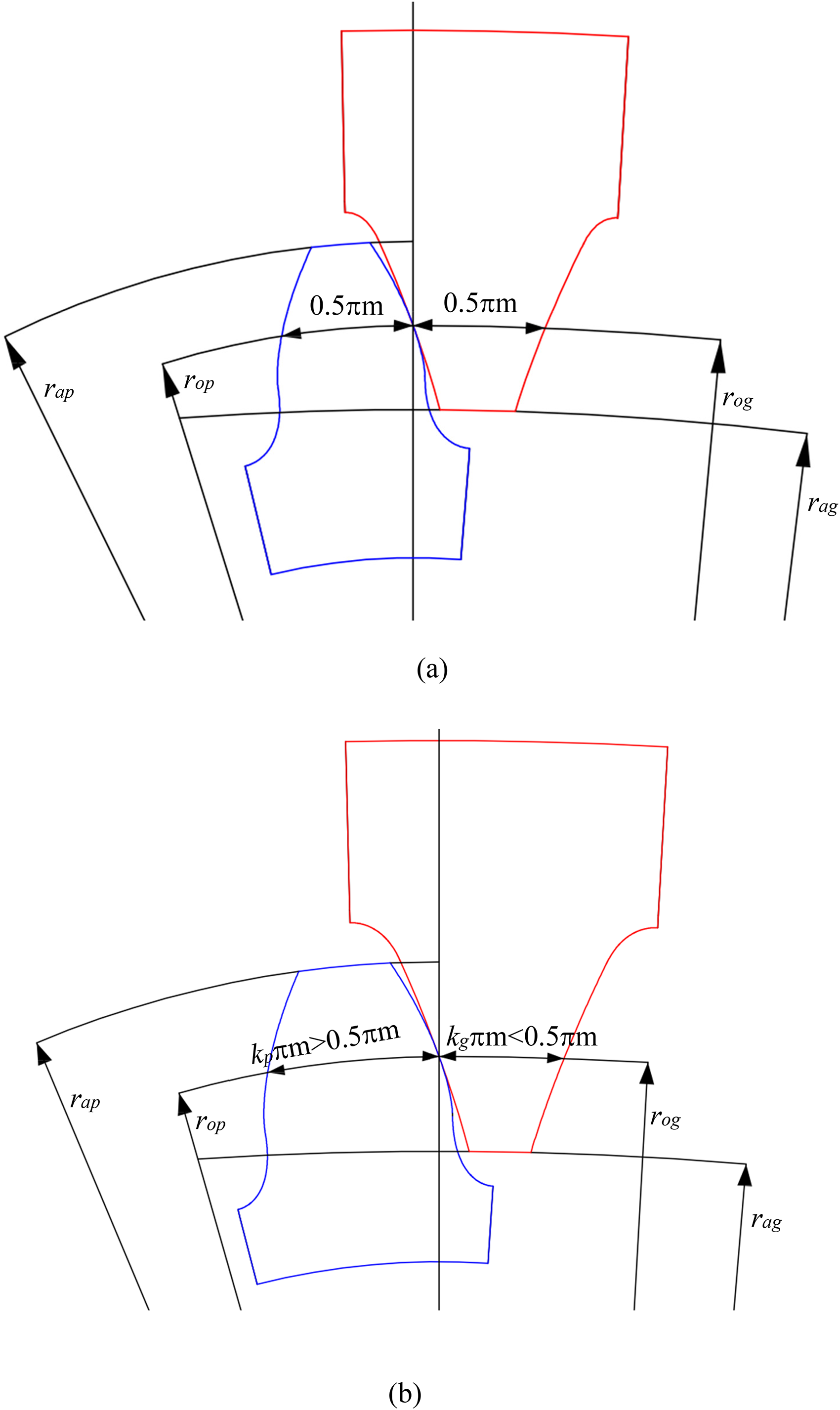
Schematic views of standard and non-standard internal gear tooth sets. (a) Standard internal gear set. (b) Non-standard internal gear set.
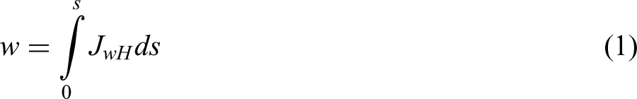
Prediction of wear in non-standard internal drive
From the authors past research24,25 on the external gear teeth, it can be observed that changing the tooth shape increases the drive ability by enhancing the tooth load distribution, which in turn advances the contact and bending strength. This adjustment to the exterior gear teeth profile also lessens slippage and lowers the anticipated tooth wear depth among the drive gears. It is crucial to precisely forecast the tooth wear in non-standard internal gear drives as it is one of the most important variables in determining system failure. In general, the teeth while mesh produces sliding and rolling motions, which result in wear on the outer layer of internal gear teeth. Here, a modified version of the Archard wear model
11
for external gear drives is utilized to forecast wear in internal gear transmission units. Generalized Archard wear equation is given in the form shown below:
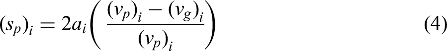
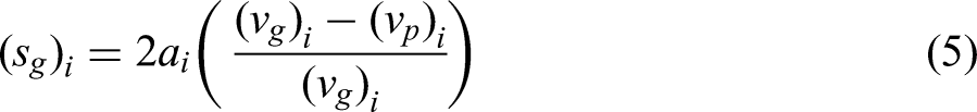
Conferring to Anderson 26 approach wear depth is evaluated by,
For external pinion,


The sliding distance (s) in the gear contact model is simplified as two cylinders in contact for assessing as specified
11
below,
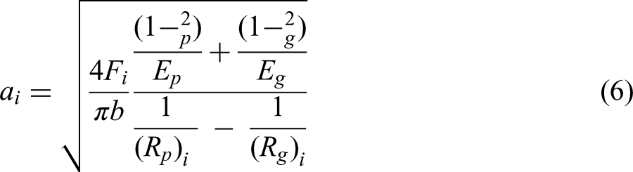


Then, the corresponding radius of curvature Rp and Rg are given as follows (Figure 2):


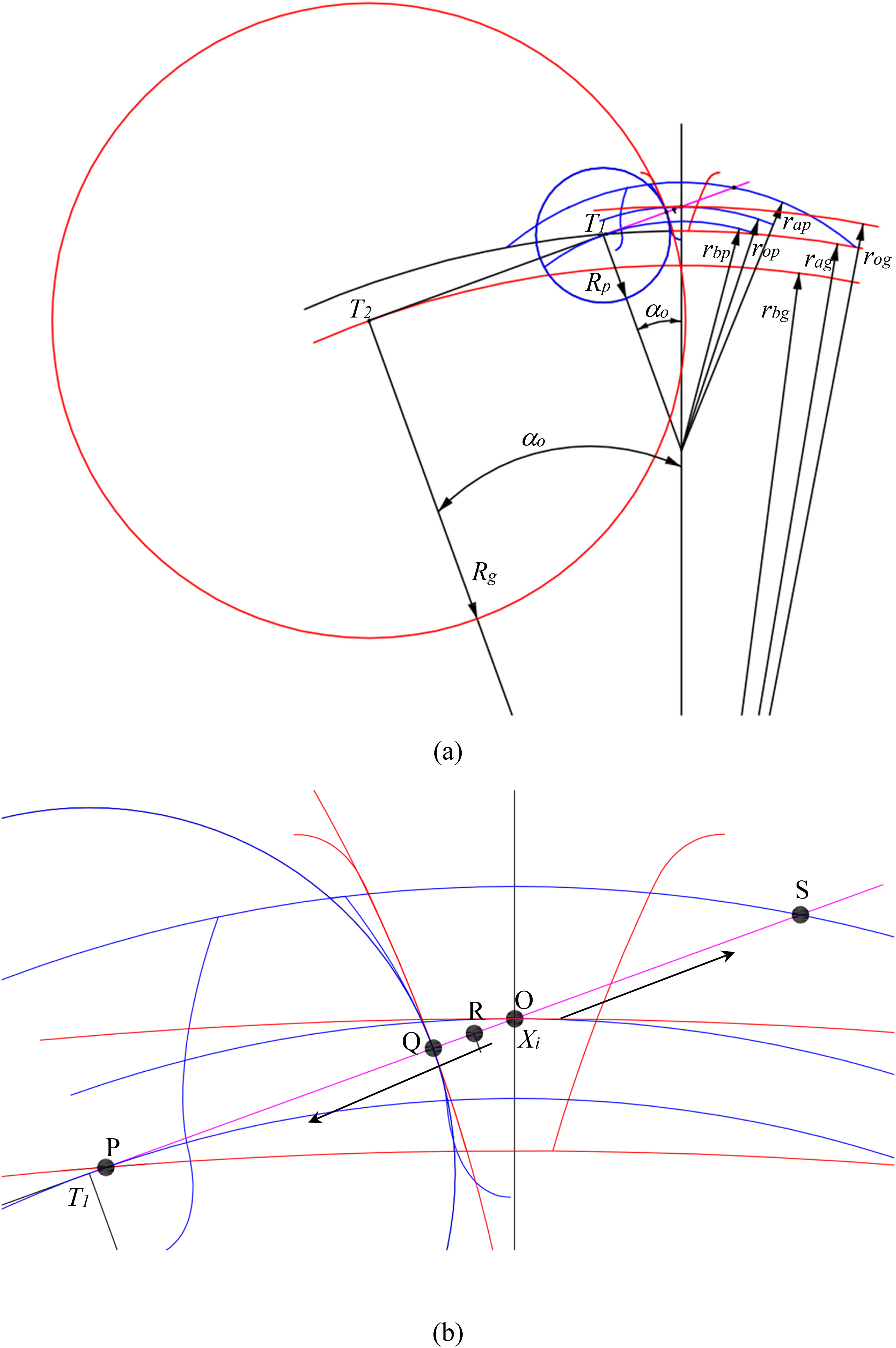
Radius of curvature at any instant point of contact.
Where Xi—distance from the pitch point to any point of contact.
Here, the distance (Xi) in Figure 2 between the two points represents the pitch point and the instant point of contact correspondingly. The point of contact may lie above or below the pitch point (reference point). From Figure 2, it is observed that the radius of the pinion cylinder (Rp) increases when the contact moves from the beginning of the contact (P) to ending of the contact (S) and at the same time Rg decreases from P to S.
Prediction of efficiency in non-standard internal drive
By introducing modifications to the tooth profile in the form of non-standard gear profiles, the loading conditions, stresses, and ultimately the drive efficiency of the gear drive are all changed. It becomes crucial to precisely forecast the power loss in the drive arrangement in order to determine efficiency and enhance the life of gears. According to the literature work of Baglioni et al. 27 taken into consideration for the analysis, the power loss is projected to occur in a time distinct periodic cycle.
The periodic power loss (PLoss) along the contact path over the mesh period is specified by,
27
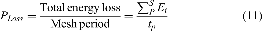

The instantaneous sliding power loss (PLi) at any instantaneous point is stated as given below:


Lubricant properties. 28
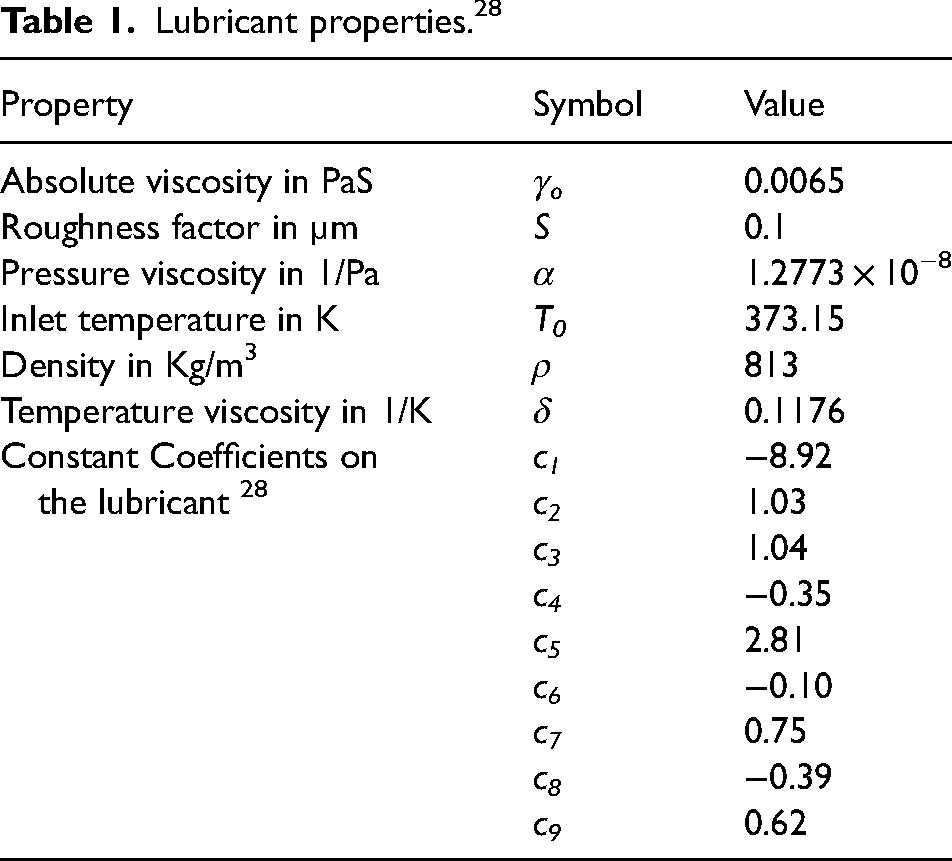
The above function is the regression equation (15) for friction coefficient prediction from the experimental work conducted by Xu
28
in his experimental setup for gear drives is given as follows: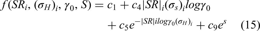


Parameters taken for study.
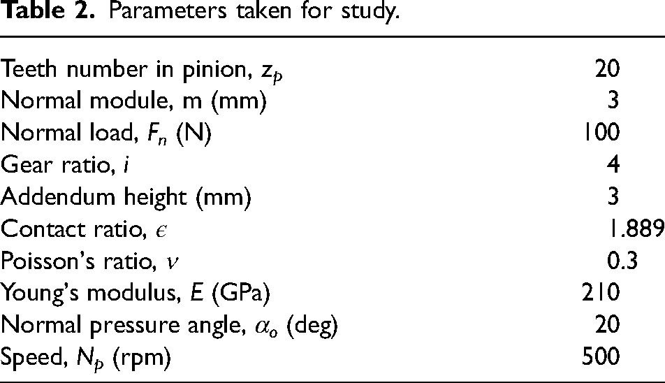
Numerical model of the internal gear drive
The finite-element model anticipates each gear as deformable bodies and engages them to compute loads, stresses, and deformations. For the specifications listed in Table 2, a 2D quadrilateral Plane 42 element is used for the internal gear pair finite-element model. Ansys Parametric Design language program is developed for the generation of the internal involute gear and external pinion model. The elements CONTA 172 and TARG 169 are used for the analysis (Figure 3). The crucial regions are determined for the contact analysis and discretized with fine mesh sections for the proper node to node interaction. To determine the ideal calculation time for the FEM-created gear system, a convergence study of the complete model has been done. Based on the convergence analysis, 16,07,124 elements have been chosen in total. Since the load distribution over the face width is uniform, the investigation is carried out under the plane strain condition. The primary assumption of the material is considered as homogenous, isotropic, and linear elastic. Actual support conditions are included in the model as hub of the pinion is applied with an equivalent torque (T) in the tangential clockwise direction (T = Fn × rbp) and restrained in the radial direction whereas the gear is restrained in all the direction. The face width (b) is taken as unit width in the 2D finite-element analysis. The contact load (Fi), fillet (σt), and contact stresses (σH) are determined through finite-element analysis. Further, the calculated contact stress (σH) is used to evaluated the tooth wear and gear drive efficiency in this research work.
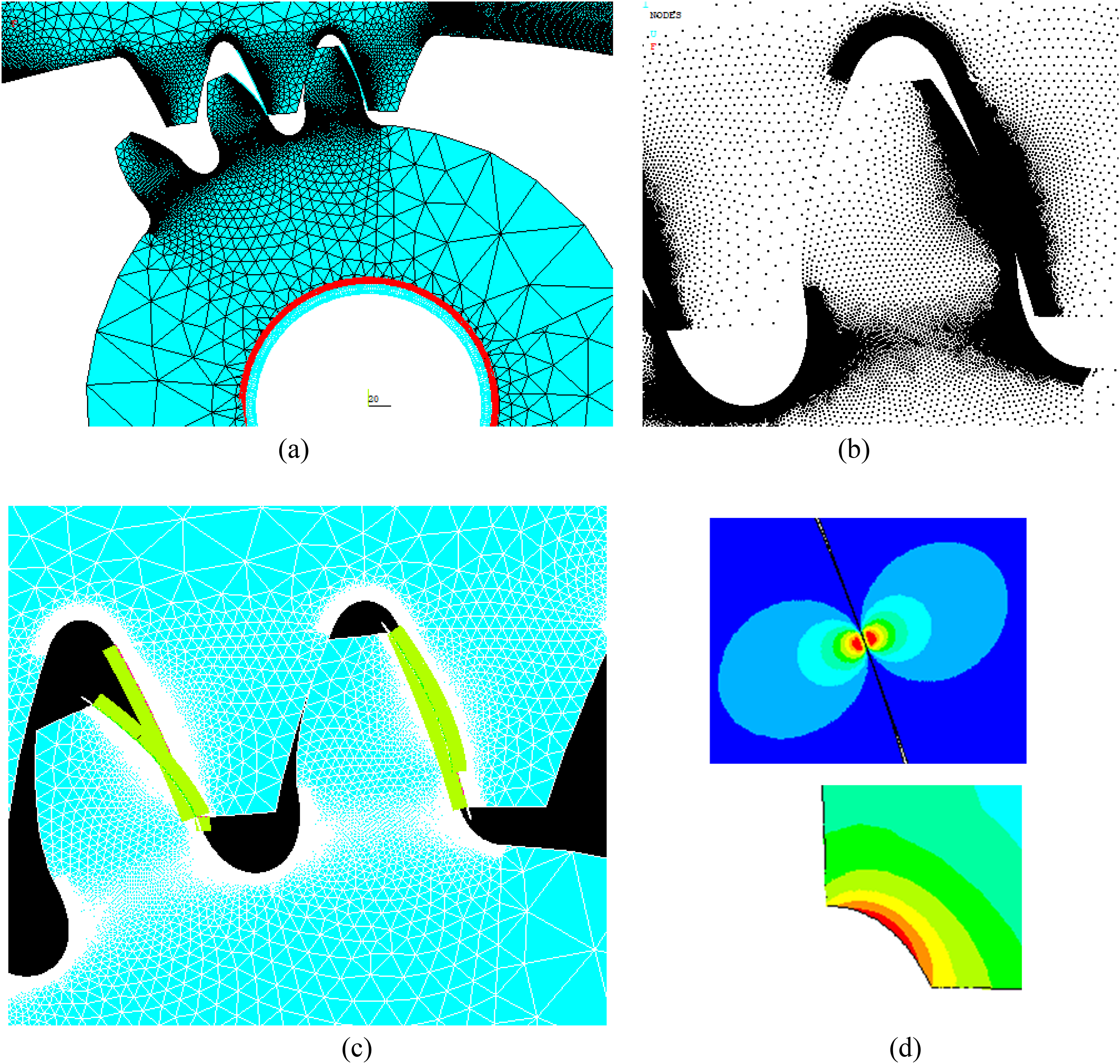
A view of the FE model. (a) FE model of three-pair internal gear. (b) Density of node distribution at critical regions. (c) Meshing contact regions. (d) Contact and bending stresses.
Computed non-standard internal gear set performance results
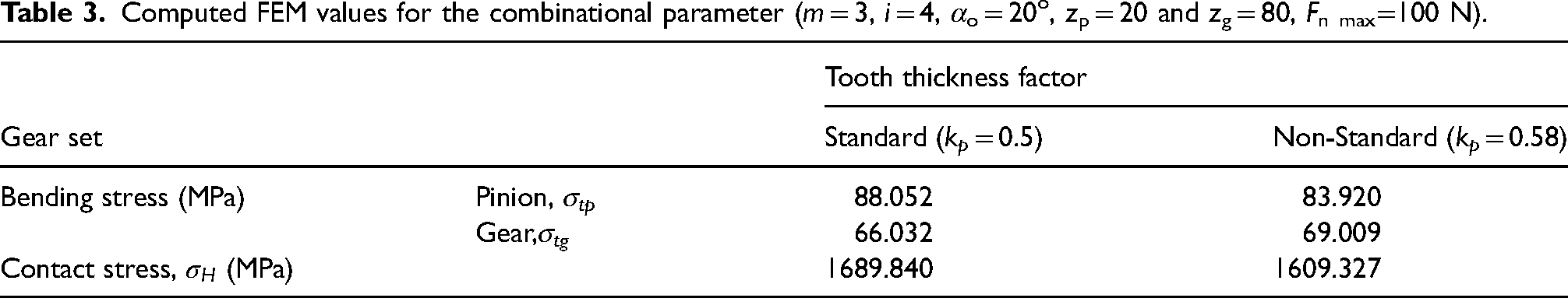
At the pitch circle, the tooth thickness is varied from the usual value of 0.5 to produce the non-standard internal gear profile. As the value of bending stress is less in gear wheel compared to the pinion hence reducing the stress in the pinion gets its importance. To improve the bending strength in the pinion, the tooth thickness factor of pinion kp is varied to obtain less bending stress compared to the bending stress at standard value of 0.5. For this parametric combination of m = 3, i = 4, αo = 20o, zp = 20 and zg = 80, a factor named bending stress factor (Yt) is determined based on equation (22) using the computational values of bending stress ((σt) FEM ) attained through FE model. Here the bending stress factor can be used to access the bending stress for any value of the maximum load without the use of FE analysis. The bending stress factor is assessed based on equation (22) for variations in tooth thickness factor from 0.5 to 0.6 (m = 3, i = 4, αo = 20o, zp = 20 and zg = 80), and the optimum value is carefully chosen as shown in Figure 4 (a). The range is chosen from 0.5 to 0.6 as it is essential to assign larger values to the pinion to reduce the stresses. From the Figure 4(a), it is evident that at 0.58 of tooth thickness, the stress value is low compared to the other values. Thus, the optimal values of tooth thickness are chosen at 0.58 for pinion and 0.42 for gear as the total tooth thickness to be maintained as πm (0.58 πm + 0.42 πm).
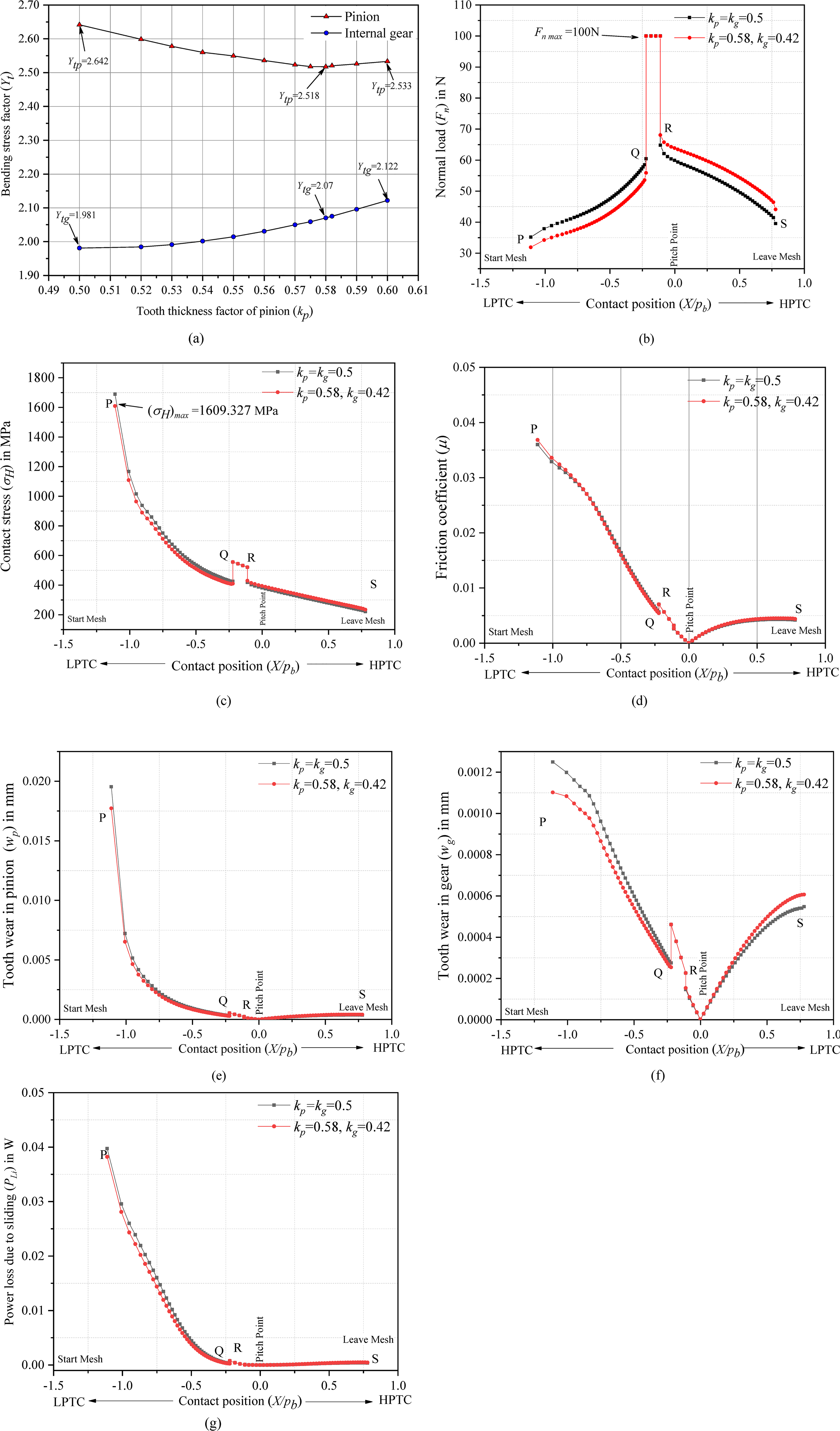
Comparison between the gear sets (m = 3, i = 4, αo = 20o, zp = 20). (a) Variation of bending stress factor for different kp. (b) Normal load (Fn) vs contact position. (c) Contact stress (
The bending stress factor (Yt) is given as follows: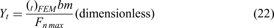
Computed FEM values for the combinational parameter (m = 3, i = 4, αo = 20o, zp = 20 and zg = 80, Fn max=100 N).
Standard and non-standard variation of wear depth in external pinion and internal gear predicted using equation (2) and equation (3) are shown in Figure 4(e and (f)). When meshing starts, it is seen that tooth wear is high at the tip (P) of the internal gear tooth, whereas, for external pinion, it is maximum in the flank region due to the combined effects of maximal contact pressure and sliding distance. It is also inferred that the wear resistance in both pinion and internal gear tooth improves in the first double-pair contact region (PQ) of the non-standard internal gear drives (Figure 4(e and (f))). This is because of the reduced contact load and the respective contact stress in the PQ region (Figure 4(b and (c))). Since there is no sliding action in the pitch point, there is no wear at that point. From the computed tooth wear for internal gear and external pinion, it is evident that the tooth wear in the pinion (wp) is almost double than the amount in the internal gear (wg) as the pinion is minor and has a greater number of rotations compared to gear. Hence wp is discussed in detail in the impending segment of parametric analysis. The sliding power loss, which is depicted in Figure 4(g), is less in non-standard internal gear drive due to reduced contact load (equation (13)).
Contact stress analysis
As a joint result of the profile alteration and operational constraints such gear ratio, teeth number, pressure angle and module the contact stress (σH) varies. Since the contact stress fluctuates at each instantaneous contact positions of mesh cycle of the internal gear pair, the maximum contact stress point is identified at the first engagement of contact at point P as revealed in Figure 4(c). Figure 5 displays the variations of each operating parameters with respect to the maximum contact stress
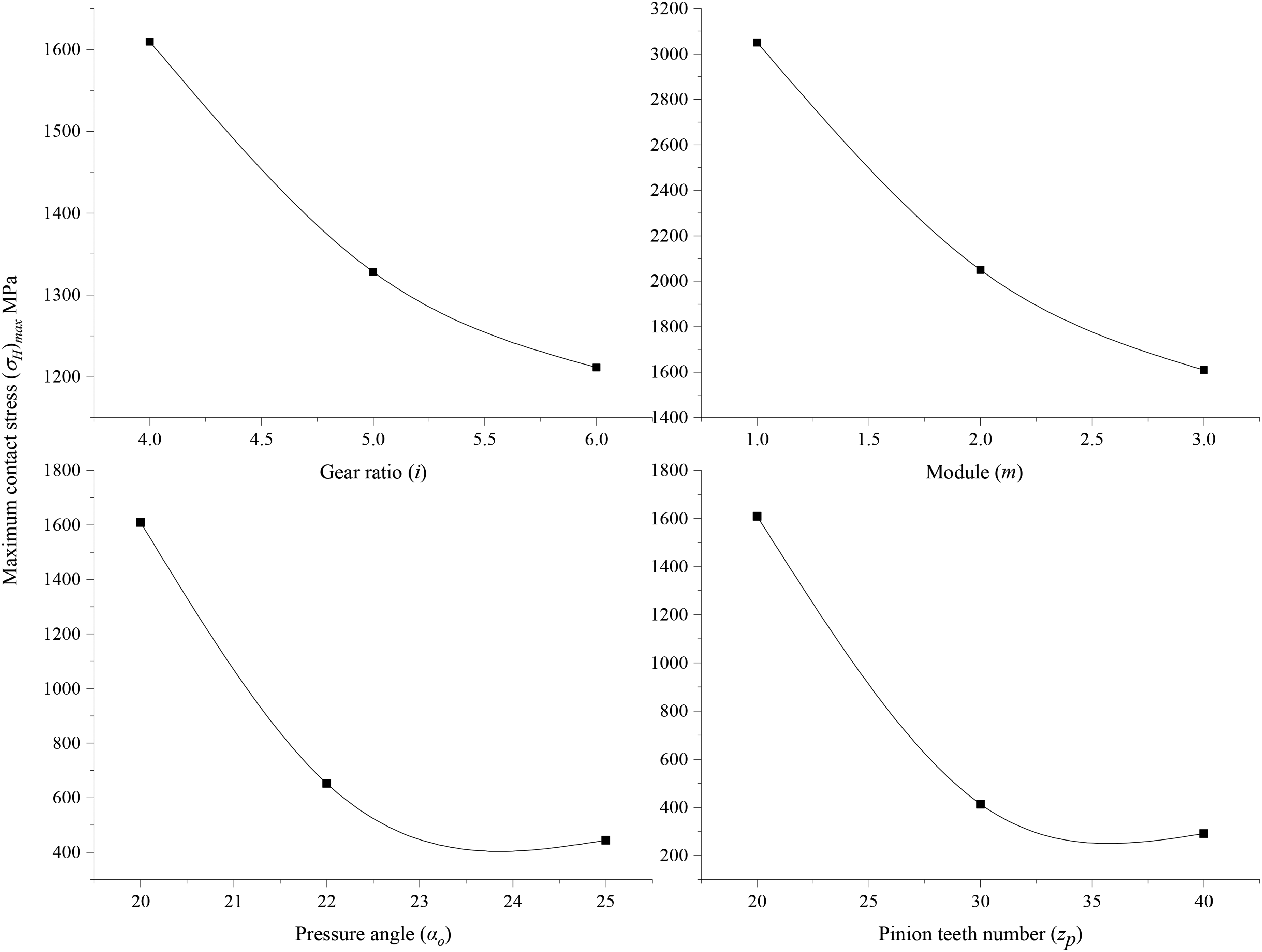
Maximum contact stress
Parametric analysis
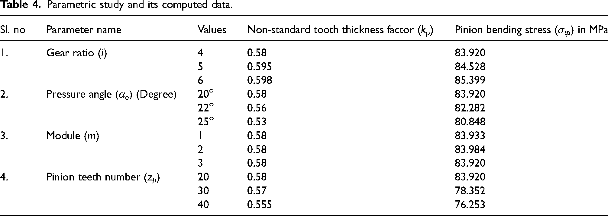
To establish the ideal value of the pinion tooth thickness factor (kp) for a lower maximum root stress regarding various parameters like zp, αo, m, and i detailed parametric research is needed as listed in Table 4. Additionally, the impact of kp is investigated regarding to contact load, stress, sliding distance, friction coefficient, tooth wear, power loss, and efficiency of the non-standard internal gear drive system.
Parametric study and its computed data.
Variation of gear ratio (i)
Figure 6 illustrates the variations in the load share, friction coefficient, tooth wear, and sliding power loss for various combinations of gear ratios (i = 4, 5, and 6). The tooth thickness factor is obtained for various combinations of gear ratio (i = 4, 5, and 6) and the value tends to increase from 0.58 to 0.598 to obtain a reduced maximum bending stress in the external pinion as shown in Table 4. Both the tooth thickness factor (kp) and the bending stress (σtp) increases in the pinion which is mainly because of the effect of increased bending moment arm in the pinion with larger gear ratios. Increased friction coefficient (µ) is obtained for increasing gear ratio because of the effect of increasing equivalent radius of curvature (Figure 6(b)). However, as the contact stress and the sliding distance decrease at point P, the maximum tooth wear indicated in Figure 6(c) at the first site of engagement at P decreases to a significant amount for increasing gear ratio (i). The load-dependent sliding power loss (P Li ) (Figure 6(d)) tends to grow along the contact path as the friction coefficient rises. The friction coefficient parameter has a noteworthy influence on the power loss since the load distribution along the mesh cycle is nearly same in the regions of interest PQ (Figure 6(a)).
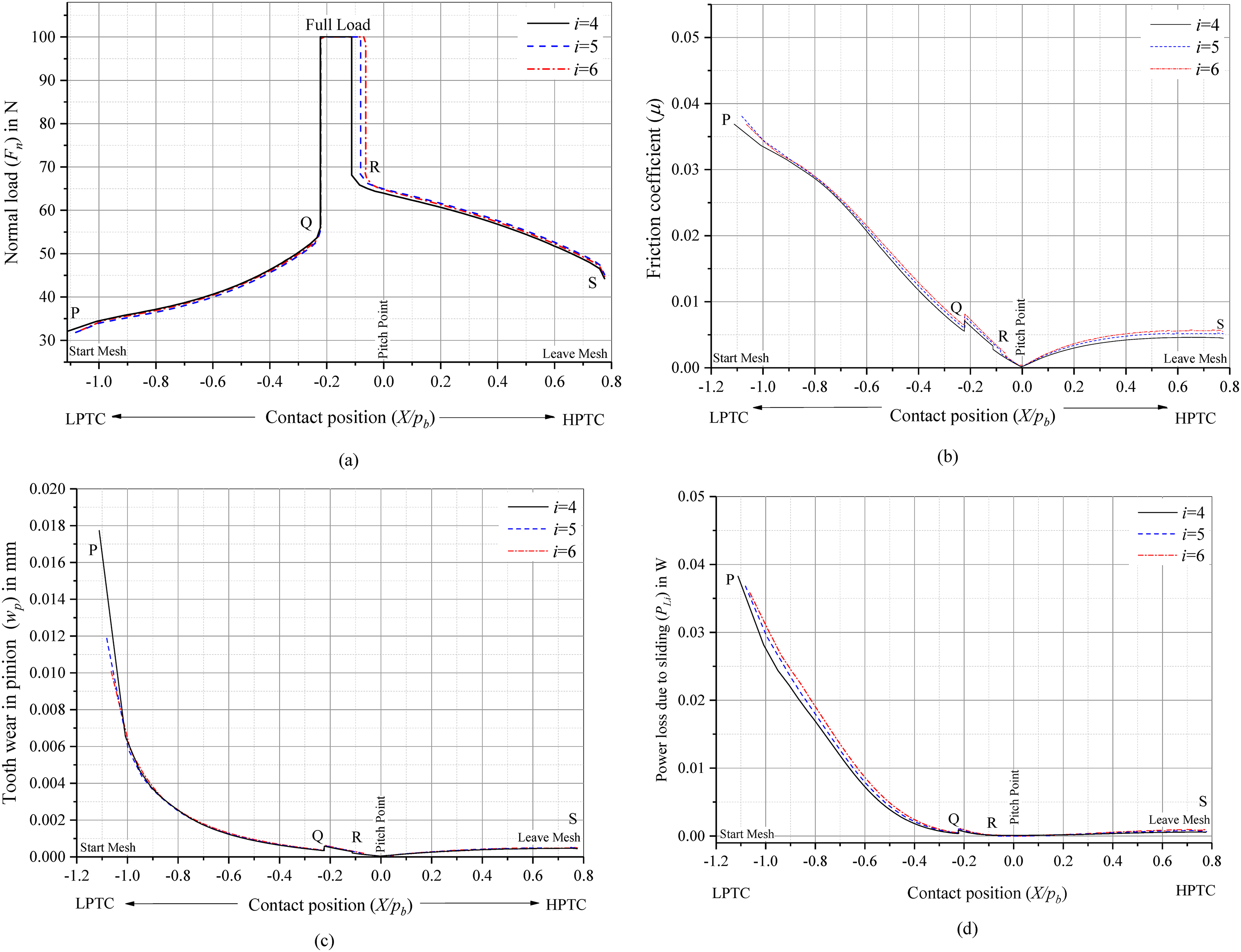
Variation of gear ratio (i). (a) Normal load (Fn) vs contact position. (b) Friction coefficient (µ) vs contact position. (c) Tooth wear for pinion (wp) vs contact position. (d) Sliding power loss (PLi) vs contact position.
Variation of pressure angle (αo)
Table 4 lists the non-standard tooth thickness factor for increasing pressure angles (20o, 22o, and 25o). It has been discovered that as pressure angle increases, the tooth thickness in the internal gear increases which ultimately reduces in the external pinion. In Figure 7(a), the increase in pressure angle results is shown in the load share distribution along the mesh cycle. The computed load at the contact point P increases with a same amount of decrease at the contact point R. The rise in the pressure angle results in decline in the friction coefficient, as exhibited in Figure 7(b). As the slide to roll ratio and the maximum contact stress lowers (Figure 5), the friction coefficient is reduced primarily as a result. In Figure 7(c), the tooth wear decreases with the rise in the pressure angle. This reduction of tooth wear depth (wp) at different meshing points along the mesh cycle is primarily due to the combinational effect of reduced contact stress and sliding distance. Additionally, as revealed in Figure 7(d), the friction coefficient decreases according to load share distribution, reducing the sliding power loss throughout the line of action.
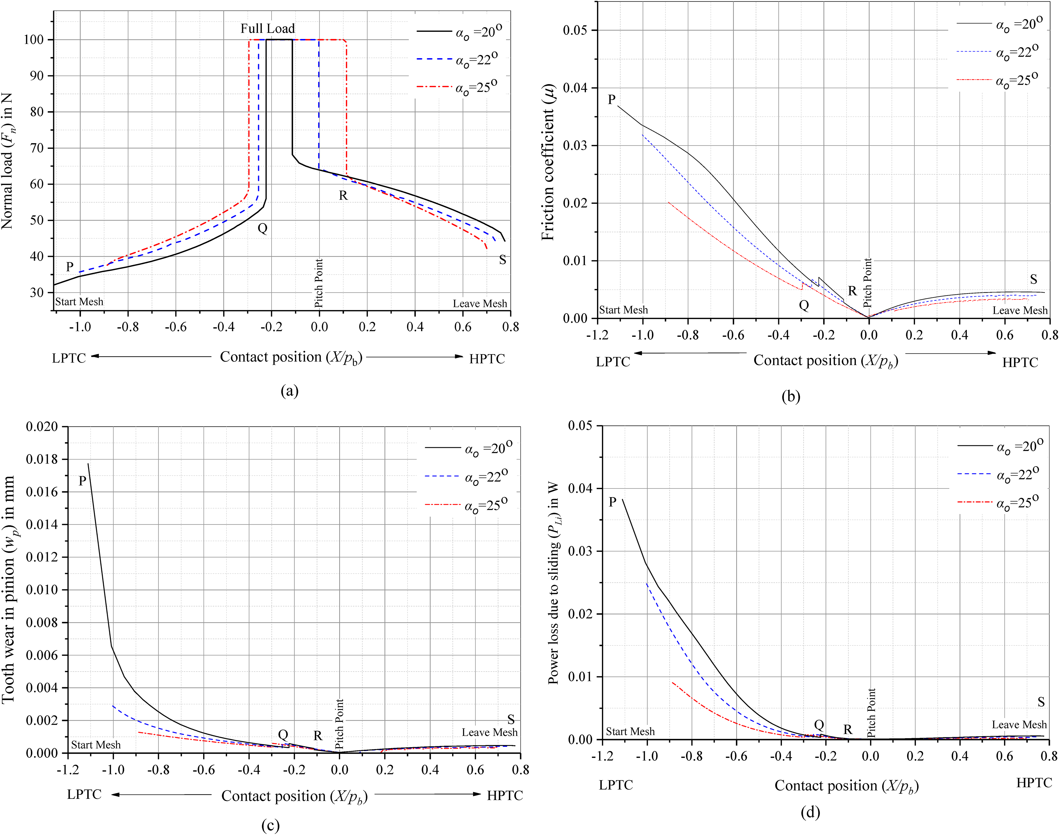
Variation of pressure angle (αo). (a) Normal load (Fn) vs contact position. (b) Friction coefficient (µ) vs contact position. (c) Tooth wear for pinion (wp) vs contact position. (d) Sliding power loss (PLi) vs contact position.
Variation of module (m)
Figure 8 illustrates the variations in the load share, friction coefficient, tooth wear depth, and power loss across different normal modules (m = 1, 2 and 3). It is apparent from Table 4, that there is no difference in the non-standard tooth thickness (kp), which is 0.58 in all situations for the various modules. Due to the same tooth thickness and bending stress for the changing module, the contact load sharing is also similar as displayed in Figure 8(a). But a notable reduction in the contact stress (Figure 5) is seen by expanding the module which significantly influences the reduction of friction coefficient as the equivalent radius of curvature is also decreasing. Almost similar values in the wp are seen as the sliding distance variation is also same along the line of action which resembles in the tooth wear depth variation displayed in Figure 8(c). The maximum tooth wear depth at the first site of engagement at P shows very little variance. The power loss (Figure 8(d)) in the internal gear drive (equation (13)) for increasing module seems to be increasing mainly because of the effect of difference in peripheral velocity of the external pinion (vp) and internal gear (vg) which overwhelms the effect of reducing friction coefficient in the drive system.
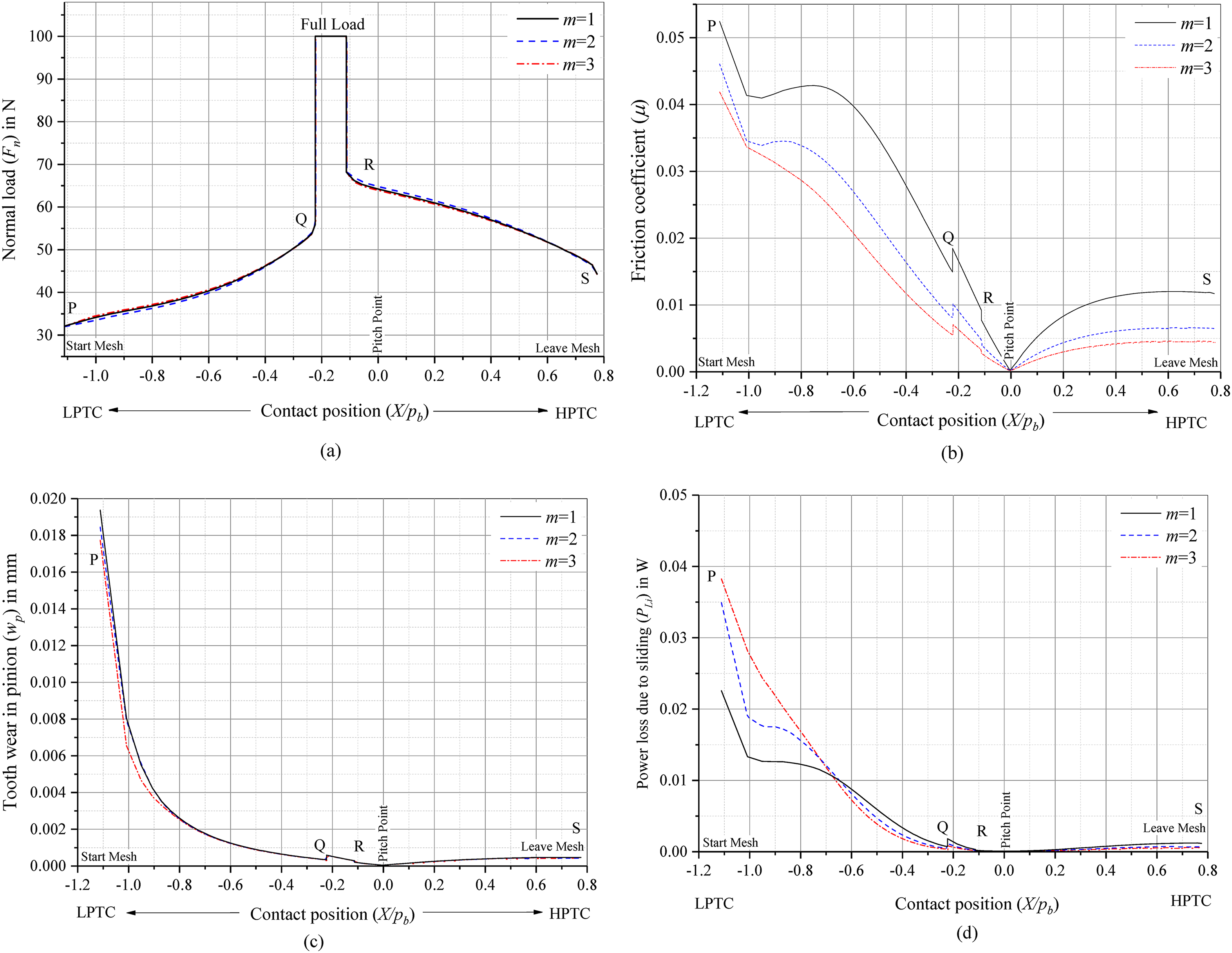
Variation of module (m). (a) Normal load (Fn) vs contact position. (b) Friction coefficient (µ) vs contact position. (c) Tooth wear for pinion (wp) vs contact position. (d) Sliding power loss (PLi) vs contact position.
Variation of teeth number (zp)
Figure 9 illustrates the variation in the load share, friction coefficient, tooth wear, and the power loss due to sliding for varying pinion teeth number. The tooth thickness tabulated in Table 4 is reducing from 0.58 to 0.555 for the increasing teeth number from 20 to 40. This is by the fact that larger teeth number which reduces the effect of tooth thickness at the reference circle. The variation in the load share (Figure 9(a)) is seen in the double-pair contact regions PQ and RS for the varying teeth number. In the scenario of increasing teeth number, the cutter tip radius also increases which lowers the bending stress in the tooth. The contact stress is declining drastically for increasing zp which obviously influences the friction coefficient (Figure 9(b)) and the individual tooth wear (Figure 9(c)) depth in the drive system. Enormous amount of reduction in power loss (Figure 9(d)) is gained by increasing the pinion teeth number as it gets influenced largely by the interaction between the contact load in the region PQ and the friction coefficient.
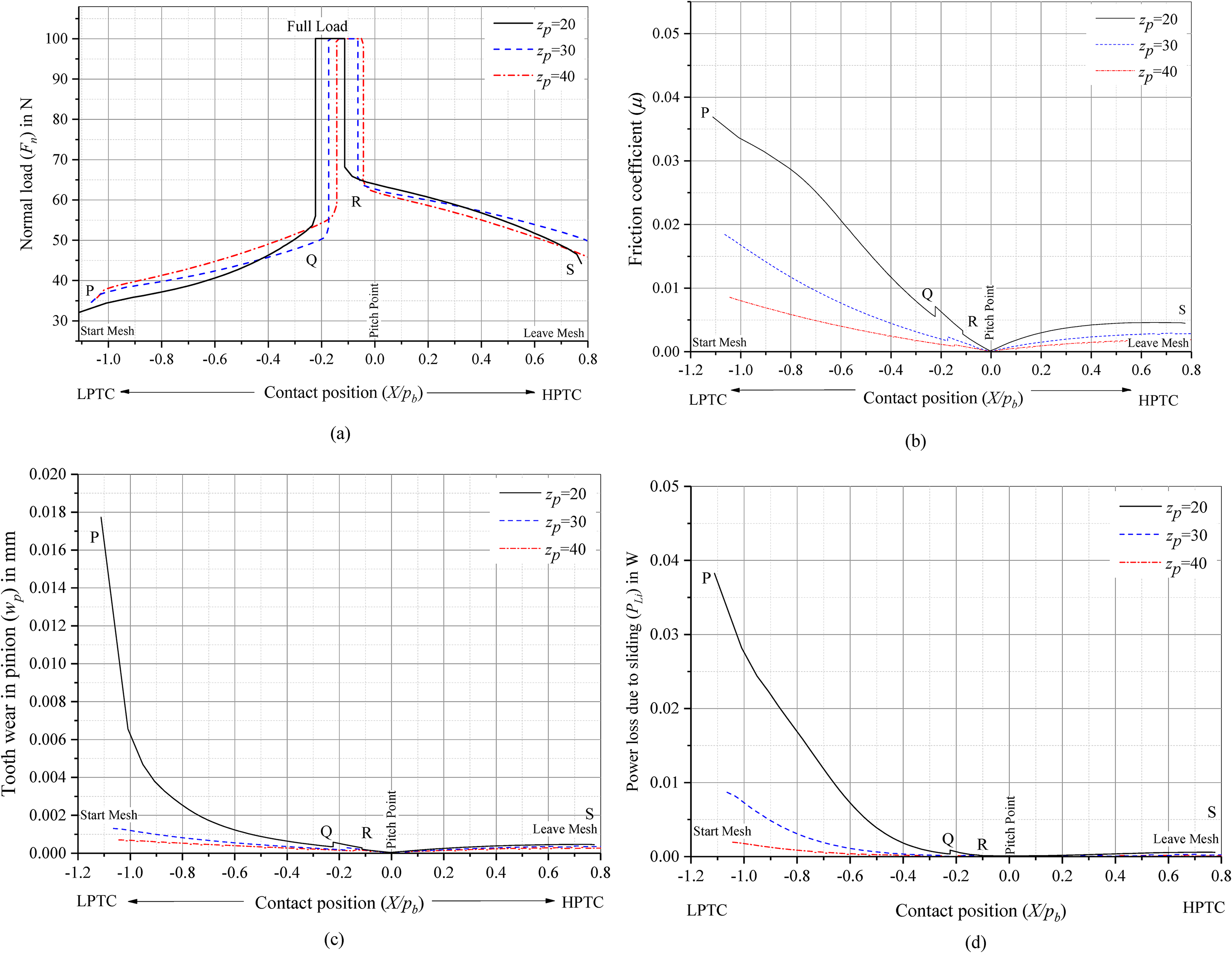
Variation of teeth number (zp). (a) Normal load (Fn) vs Contact position. (b) Friction coefficient (µ) vs contact position. (c) Tooth wear for pinion (wp) vs contact position. (d) Sliding power loss (PLi) vs contact position.
Internal gear efficiency analysis
The effect of several parameters on the mesh efficiency of internal non-standard gears is shown in Figure 10 including gear ratio, pressure angle, module, and pinion teeth number. The time period mesh efficiency is predicted and shown in Figure 10 using the equations (11–21). It is exhibited that only the efficiency of the gear ratio (i) is in falling trend when compared to the other cases has it seems to be in the raising trend. Since the power loss for the gear ratio is increasing which directly influence on the efficiency of the drive system. The outcome of size of the gear through module influences the base circle radius of the external pinion and the internal gear which increase the power input to the system thereby enhance the efficiency of the non-standard internal gear drive arrangement.
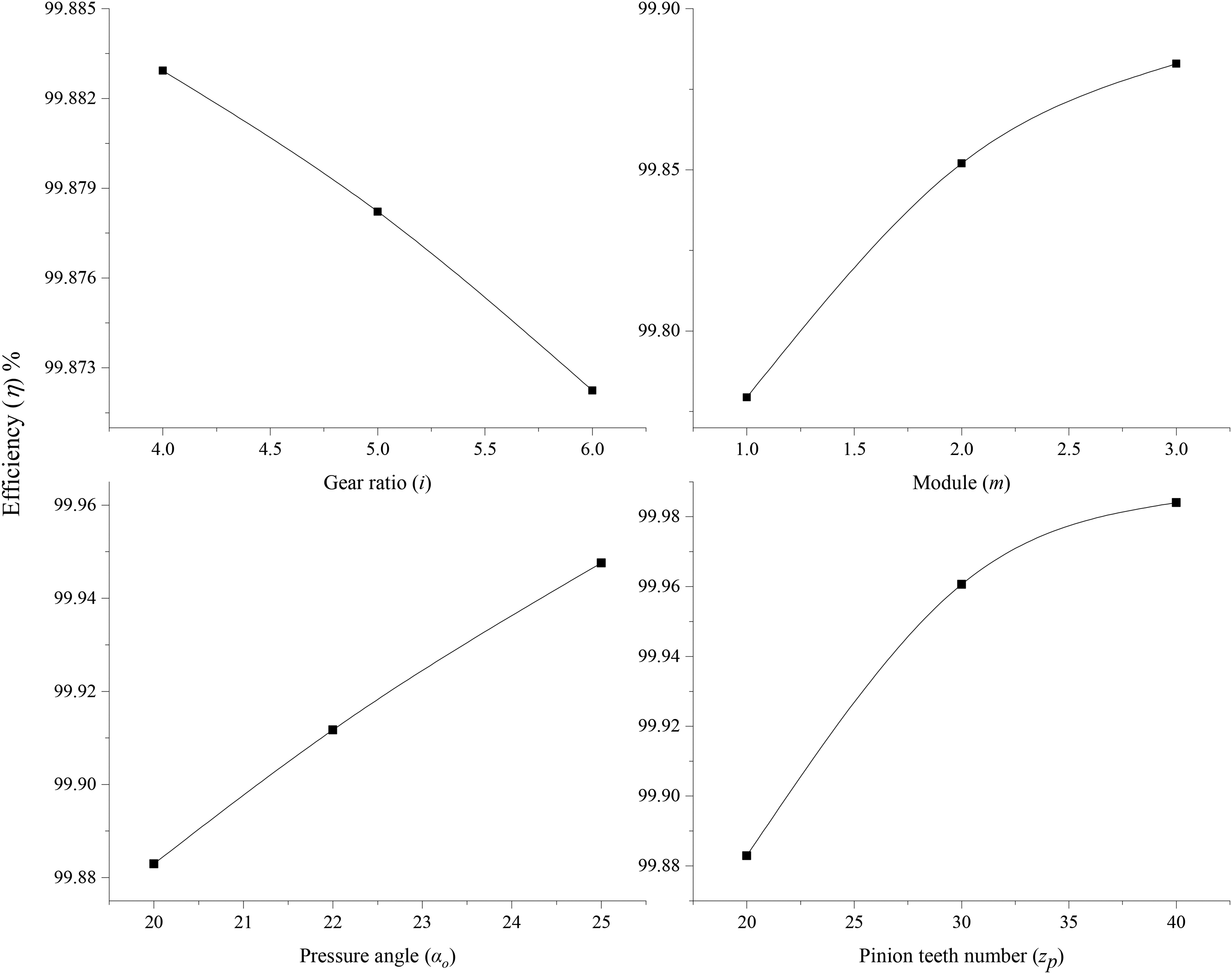
Efficiency (η) vs parameter variation.
Conclusions and future work
For the wear and time period mesh efficiency of internal spur gears with modified tooth profiles, a simple analytical model with finite-element analysis is proposed in this work. Finally, some preliminary considerations on the influence of gear ratio, pressure angle, module, and teeth number with the amount of tooth profile modifications has been reported.
Providing uneven tooth thickness of kp =0.58 enhances the bending strength, contact load carrying capacity, improves the wear resistance of external pinion and internal gear, and reduces power loss in the non-standard internal gear drives compared to the standard drive (Figure 4). By integrating non-standard tooth thickness, an improvement in the contact strength is exhibited (Figure 5) for the rising gear ratio (i), pressure angle (αo), module (m), and pinion teeth number (zp). As gear ratio i increases, tooth thickness factor (kp) increases with increase in the bending stress and equivalent radius of curvature which indirectly impact the friction coefficient and the power loss which is increasing along the contact path. This increase is seen in the reduction of efficiency for higher gear ratio (i) value of the drive arrangement. Notable reduction in the maximum tooth wear of the pinion (wp) is attained for increasing gear ratio. For the higher values of pressure angle (αo), the tooth thickness factor (kp) is obtained for a reduced bending stress and contact stress which have a significant impact on the reduction of friction coefficient and power loss due to sliding all over the mesh cycle which eventually advances the efficiency of the drive (Figure (7 and 10)). The tooth wear resistance is observed to have enhancement throughout the mesh cycle for increasing pressure angle. Due to enlargement in the size of the gear module (m), the value of tooth thickness factor (kp) is unaltered for the bending stress. Furthermore, modest increase in the power loss is seen which is because of difference in the sliding velocity (Figure 8). But this influence is not present in the efficiency of the system. As the efficiency rises for increasing module which is supported by enhanced contact strength and wear resistance. Increasing the pinion teeth number (zp) is strongly recommend as there is substantial reduction in tooth wear depth of the pinion (wp), friction coefficient, and power loss is observed (Figure 9) with enhancement in efficiency of the drive system.
Ultimately, it can be concluded from the above-mentioned findings that a non-standard internal gear drive has improved wear resistance and efficiency for larger values of operational parameters such pressure angle, module, and pinion teeth number. These findings may serve as recommendations for further research into unconventional internal gears for dynamics study under varying load circumstances.
Footnotes
Declaration of Conflicting Interests
The authors declared no potential conflicts of interest with respect to the research, authorship, and/or publication of this article.
Funding
The authors received no financial support for the research, authorship, and/or publication of this article.