
Abstract
The bearing geometry has a big impact on the performance of a hydrodynamic thrust bearing. For this reason, shape optimisation of the bearing surface has been carried out for some time, with Lord Rayleigh’s early publication dated back to 1918. There are several recent results e.g. optimal bearing geometries that maximise the load carrying capacity for hydrodynamic thrust bearings. Currently, many engineers are making an effort to include sustainability in their work, which increases the need for bearings with lower friction and higher load carrying capacity. Improving these two qualities will result in lower energy consumption and increase the lifetime of applications, which are outcomes that will contribute to a sustainable future. For this reason, there is a need to find geometries that have performance characteristics of as low coefficient of friction torque as possible. In this work, the topological optimisation method of moving asymptotes is employed to optimise bearing geometries with the objective of minimising the coefficient of friction torque. The results are both optimised bearing geometries that minimise the coefficient of friction torque and bearing geometries that maximise the load carrying capacity. The bearing geometries are of comparable aspect ratios to the ones uses in recent publications. The present article also covers minimisation of friction torque on ring bearing geometries, also known as thrust washers. The results are thrust washers with periodical geometries, where the number of periodical segments has a high impact on the geometrical outcome.
Keywords
Introduction
A thrust bearing is a vital component in many heavy machinery systems, for example in water turbines, where it carries the massive weight of the generator, the turbine as well as the shaft connecting them. This is accomplished by the bearings’ capability/ability to generate hydrodynamic pressure, in the fluid film between the rotating collar and the stationary bearing surface. It is a well-known fact that the bearing geometry plays a key role in generating the hydrodynamic pressure which, in turn, largely influences the overall performance of the bearing, i.e. the Load Carrying Capacity (LCC) and Friction Torque (FT). A high LCC will result in a thicker fluid film separating the surfaces, thereby reducing the risk of wear. A low FT, reduces the power losses, which increase the productivity of the system. In a business where maintenance stops the production and every extra percent of efficiency is important, reducing wear and power losses will potentially both reducing costs and increase profit from production. This is one of the main reasons that researchers curiously have been searching for the optimal bearing geometry, for quite some time now.
Over a century ago, Rayleigh, 1 found the bearing geometry for an infinitely wide slider which maximises the LCC. It turned out to be a step-bearing geometry, a truly astonishing achievement and well ahead of his time. Several decades later, Kettleborough, 2 discussed and elaborated on the bearing geometry for a finitely wide slider which maximises the LCC. The idea was that a pocket-bearing geometry would restrict side leakage while still having a good pressure build up. Kettleborough 2 also discussed how an optimal slider in terms of friction should be designed. He concluded that there should be an internal fluid entrapment area, where pressurised fluid can be stored in an area with a thick fluid film which provides lower shear stresses, leading to a lower Friction Force (FF). Later, Rohde, 3 investigated how a minimum Coefficient of Friction (COF) could be obtained for an infinitely wide slider. The result was a slider similar to the step-bearing geometry found by Rayleigh, 1 which differed in that the leading edge film thickness has increased, and that a relocated and tapered step now replaced the vertical one. In the same decade, Rohde and McAllister, 4 numerically optimised a finite slider finding the bearing geometry that maximises the LCC. The result was a pocket type of bearing, confirming the predictions by Kettleborough. 2
In recent years, other optimisation methods for finding the same bearing geometry as Rohde and McAllister 4 has been proven to work. Both Buscaglia et al. 5 and van Ostayen, 6 were able to replicate the results with numerical resolution far higher than what was used to obtain the solution presented in Ref. 4 The search for optimal geometries for (finitely wide) linear sliders provides understanding about the influence the geometry has on the performance of the bearing. It should, however, be noted that there is a rather limited amount of real-world engineering solutions that would benefit from the application of the such geometries. Among the real-world engineering solutions for dynamic conditions, one of the most common types of thrust bearing is the hydrodynamic fluid bearing for rotating devices (where the axial thrust is supported by the fluid film pressure generated during operation). This is why the task of optimising bearing geometries naturally shifted focus towards these. Fesanghary and Khonsari, 7 were the first to find the geometries that maximises the LCC for hydrodynamic thrust bearings. As for the finitely wide linear sliders obtained in Refs.,2,4–6 the geometries were also found to be of pocket type. The thorough work by Fesanghary and Khonsari, clearly shows that the geometries depend on the ratio between the inner and outer radius as well as the sector angle of the cylindrically shaped domain. The following year, Fesanghary and Khonsari, 8 continued the work on finding optimal geometries for hydrodynamic thrust bearings, which can be obtained if periodic boundary conditions at the leading- and trailing edge are applied, instead of Dirichlet pressure conditions. For the bearings to be as manufacturable as possible, the geometries were restricted allowing for only two discrete values for the film thickness. They specified different parameters such as the ratio between trailing land and the carved out geometry, the number of sectors as well as the ratio between inner and outer radius, and it was shown that these parameters individually influence the solution for the optimal bearing in terms of LCC. While obtaining new geometries for different kinds of applications can provide improvements for machinery. It is still important to validate these geometries with more advanced flow models. Dobrica and Fillon 9 looked in detail on the Rayleigh step bearing, compared the models based on the Reynolds- and Navier-Stokes equations, investigating the error due to the discontinuous geometry, both with thermal properties included. Their result shows that Rayleigh step has a high performance, but it also suggests that it could exist a bearing geometry with higher performance when evaluated with thermohydrodynamical simulations.
During recent years, new methods for performing topology optimisation have been developed. One of these is the Method of Moving Asymptotes (MMA), developed by Svanberg.10,11 The method was originally intended for optimisation in the area of structural mechanics but has been applied in many different areas. The algorithm is for example available in the finite element software COMSOL Multiphysics. 12 Recently, Kalliorinne et al., 13 managed to successfully implement a Reynolds’ equation based model for bearing geometry optimisation in COMSOL Multiphysics, 12 and the algorithm was able to replicate results from Refs.,1,3 as well as optimising bearings under compressible flow with different optimisation objectives.
The studies discussed previously presents several important findings with regards to axial bearing geometries, but yet no one has presented a geometry optimised for reduction of friction torque FT. With new tools for optimising bearing geometries at hand, opportunities arise to uncover new innovative geometrical designs for bearings. In the present work, optimisation was carried out to find the bearing geometry that maximises the LCC and the bearing geometry that minimises the Coefficient of friction Torque (COT), i.e. the ratio between FT and LCC. Lastly, the minimisation of the COT was carried out on a ring bearing geometry i.e. a thrust washer, with a periodical geometry with different number of sections. The findings contribute to the understanding of how the optimal bearing geometry should be shaped, thereby aiding bearing designers and manufactures to bring new innovations to life.
Governing equations
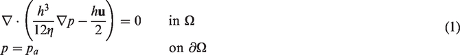
In the present work the Reynolds equation is adopted to model incompressible thin film flow over the computational domain Ω. That is


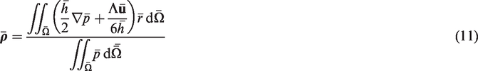
Optimisation methodology
To generalise the model, i.e. enabling the optimal geometries to be scaled depending on the operating condition or the fluid properties, the governing equation (1) can be non-dimensionalised as


In addition to ro, θp and Λ, it is necessary to specify lower- and upper limits for the film thickness as input. These are specified (in dimensionless form) as

In dimensionless form, the LCC (equation (2)) can be expressed as


The COT can also be explicitly formulated as
The non-dimensionalised form of equation (5) for thin film flow, was implemented inside Coefficient Form PDE Physics Interface in COMSOL Multiphysics®, while the initial film thickness equation (6) and the film thickness limits (equation (7)) were implemented inside the Optimization Physics Interface, and depending on the case study, the value of either (equation (8)) or (equation (10)) were specified as the objective function, to be either maximised or minimised. A cavitation model has not been employed, but it was tested without any effects on the result, the reason is that a cavitated region is suboptimal. Of course, the viscosity in a cavitated area is almost zero, which could aid friction reduction, however, the fluid takes the cavitated pressure in the region which is detrimental to the LCC, therefore, cavitation will not occur for an unidirectional optimal bearing geometry.
Results and discussion
In the following sections, three unique geometrical optimisation cases for hydrodynamic thrust bearings were studied. That is, optimisation in order to maximising the LCC, minimise the COT and minimise COT for a thrust washer plate, with computational domain with
Maximising LCC
In this section, the result of maximising the LCC using two different mesh resolutions (
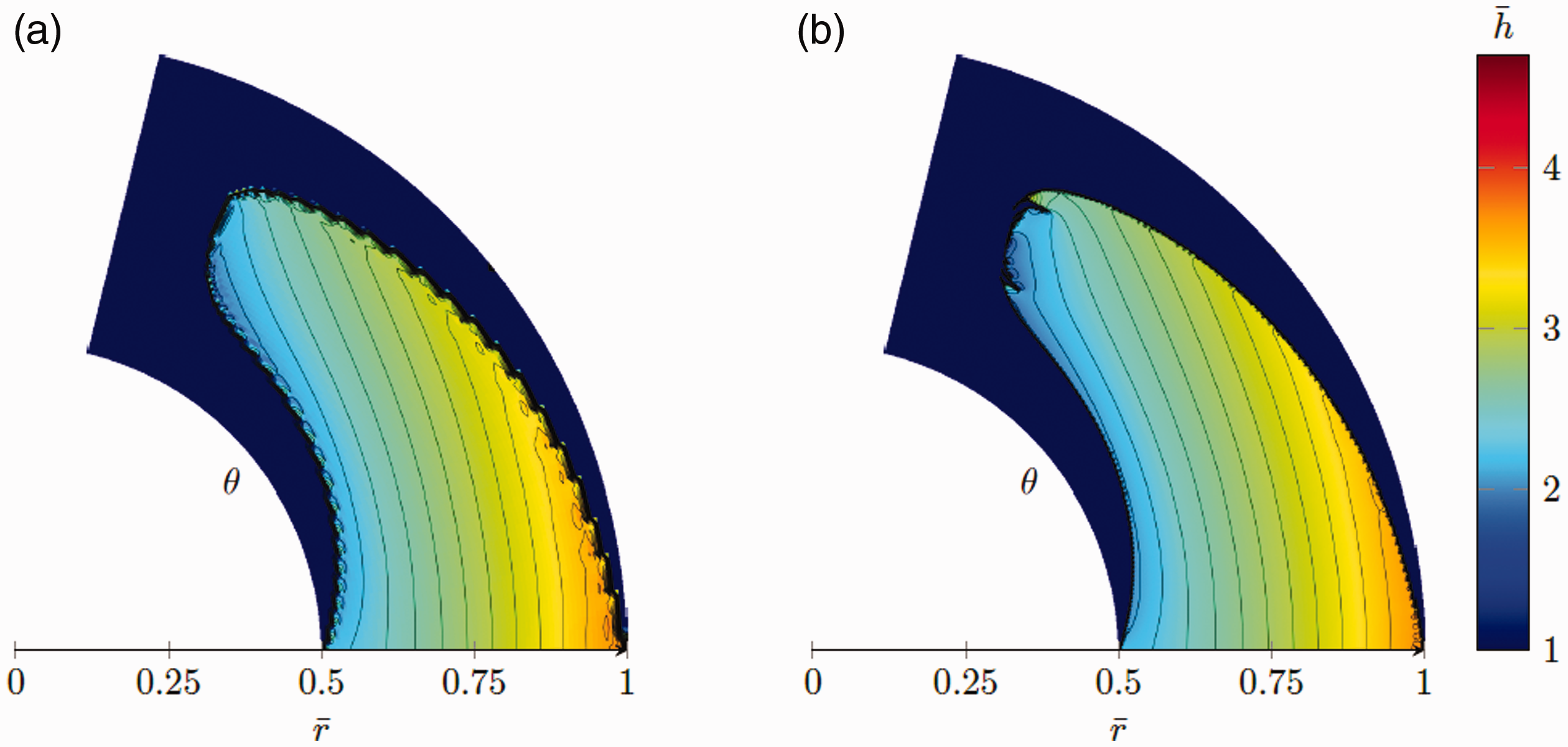
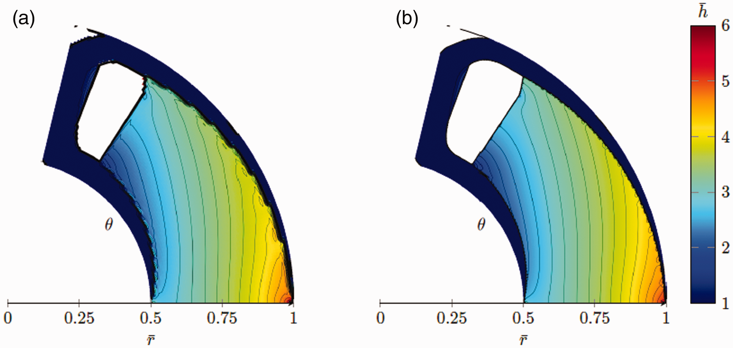
The bearing geometries that maximises LCC for two differently refined meshes, with contours levels. (a)
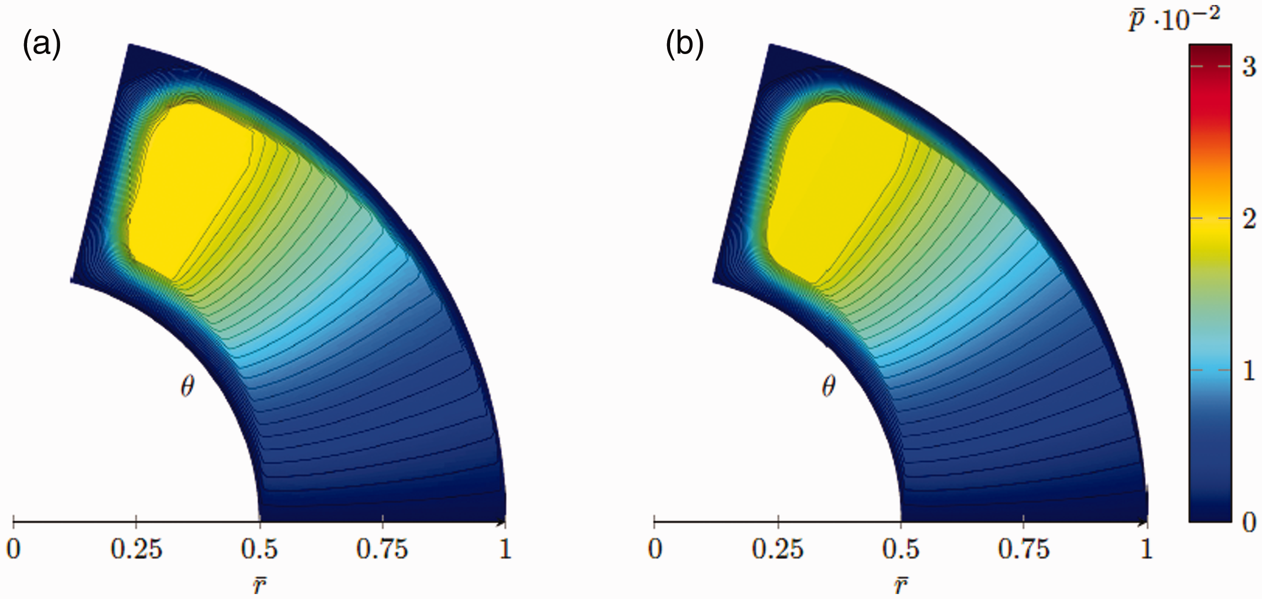
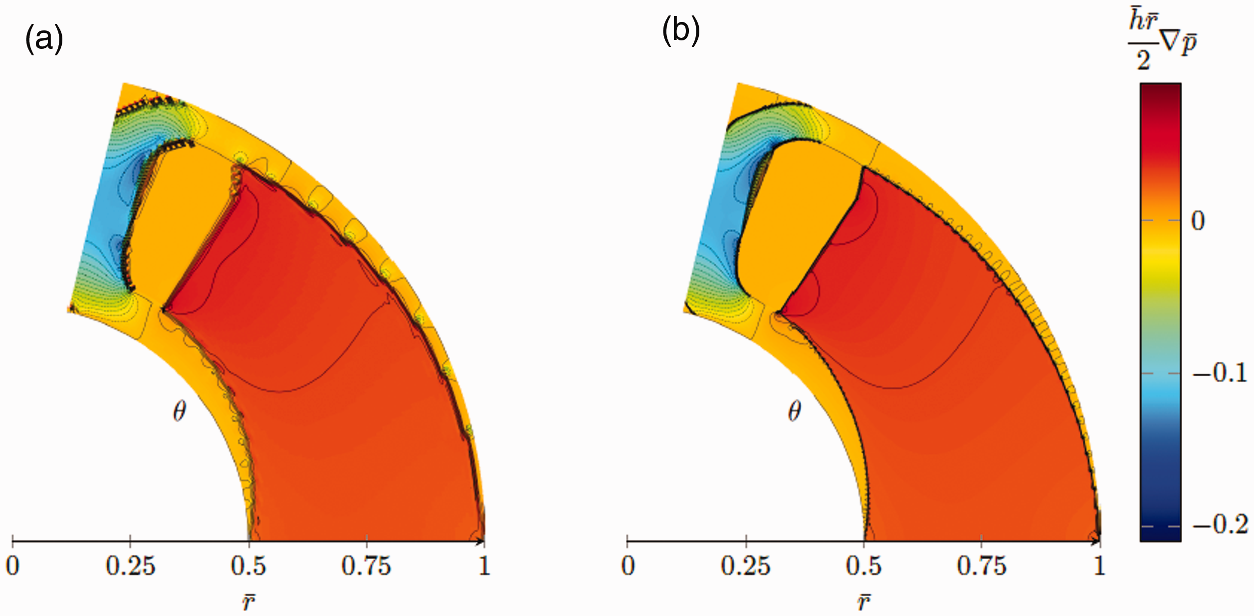
The corresponding pressure distribution to the bearing geometries shown in Figure 1 are depicted in Figure 2. The pressure distribution tells us that the maximum pressure can be found at the trailing edge of the pocket. The only difference between the results from the two mesh refinements, is that the influence of the shark fins can be seen in the area where the pressure reaches its maximum (see Figure 2(b)), which also results in a slightly increased maximum pressure.
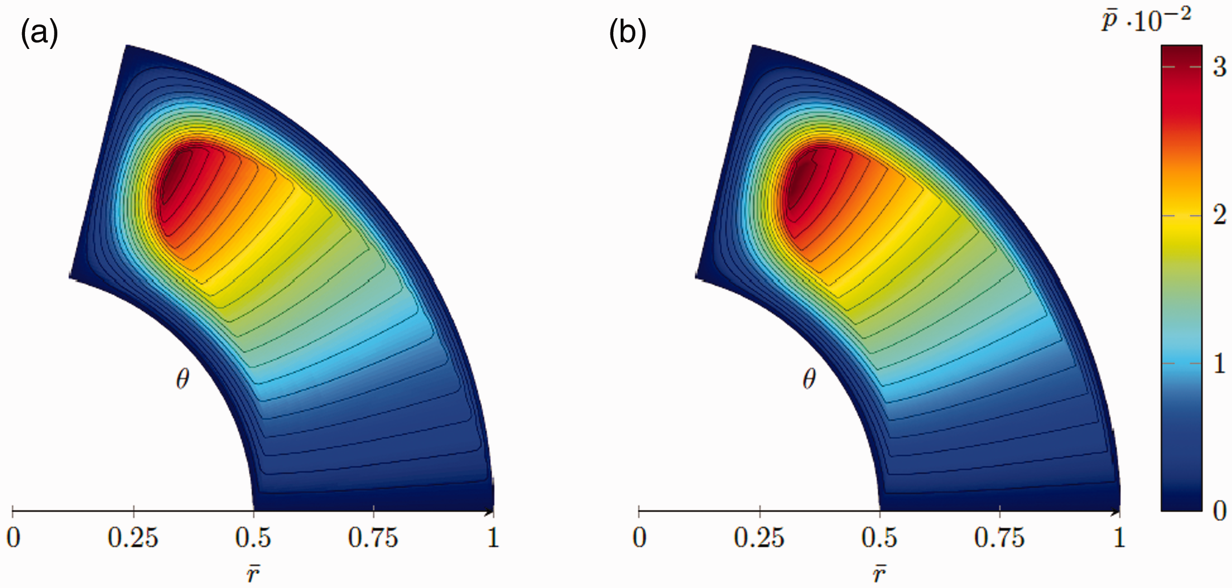
The pressure distribution corresponding to the bearing geometries that maximises LCC for two differently refined meshes. (a)
Figure 3 depicts the Poiseuille-flow shear stresses corresponding to bearing geometries in Figure 1. The Poiseuille-flow shear stress distribution shows that all contribution to the rotational resistance can be traced to the inside of the pocket, where it takes an almost constant value. The bearing land on the sides of the pocket exhibits nearly no shear stresses at all, however the area behind the pocket exhibits a negative shear stress which is actually pushing the bearing forward. The peak minimum and maximum values for the Poiseuille-flow shear stress can both be found on the distribution corresponding to the mesh with finer resolution.
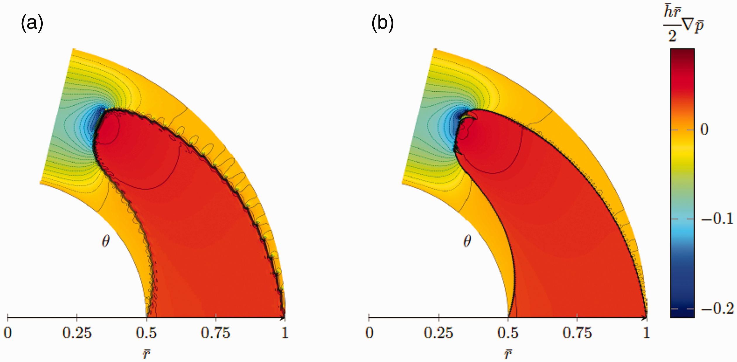
The Poiseuille-flow shear stresses corresponding to the bearing geometries that maximises LCC for two differently refined meshes. (a)
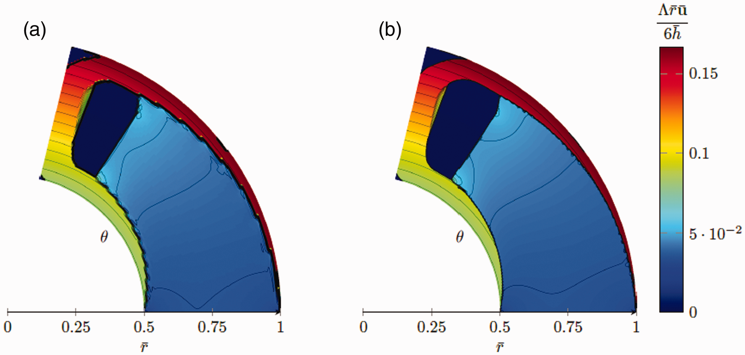
Figure 4 depicts the Couette-flow shear stresses corresponding to the bearing geometries in Figure 1. The Couette-flow shear stress distribution shows that the maximum shear stresses can be located on the outer most parts of the bearing land, where the largest velocities are found, and the film thickness is the smallest. As expected, the shear stresses are varying linearly on the land with the radius, since the speed increases linearly. Inside the pocket the shear stresses are lower and takes an almost constant value, since the film thickness is large in this region.
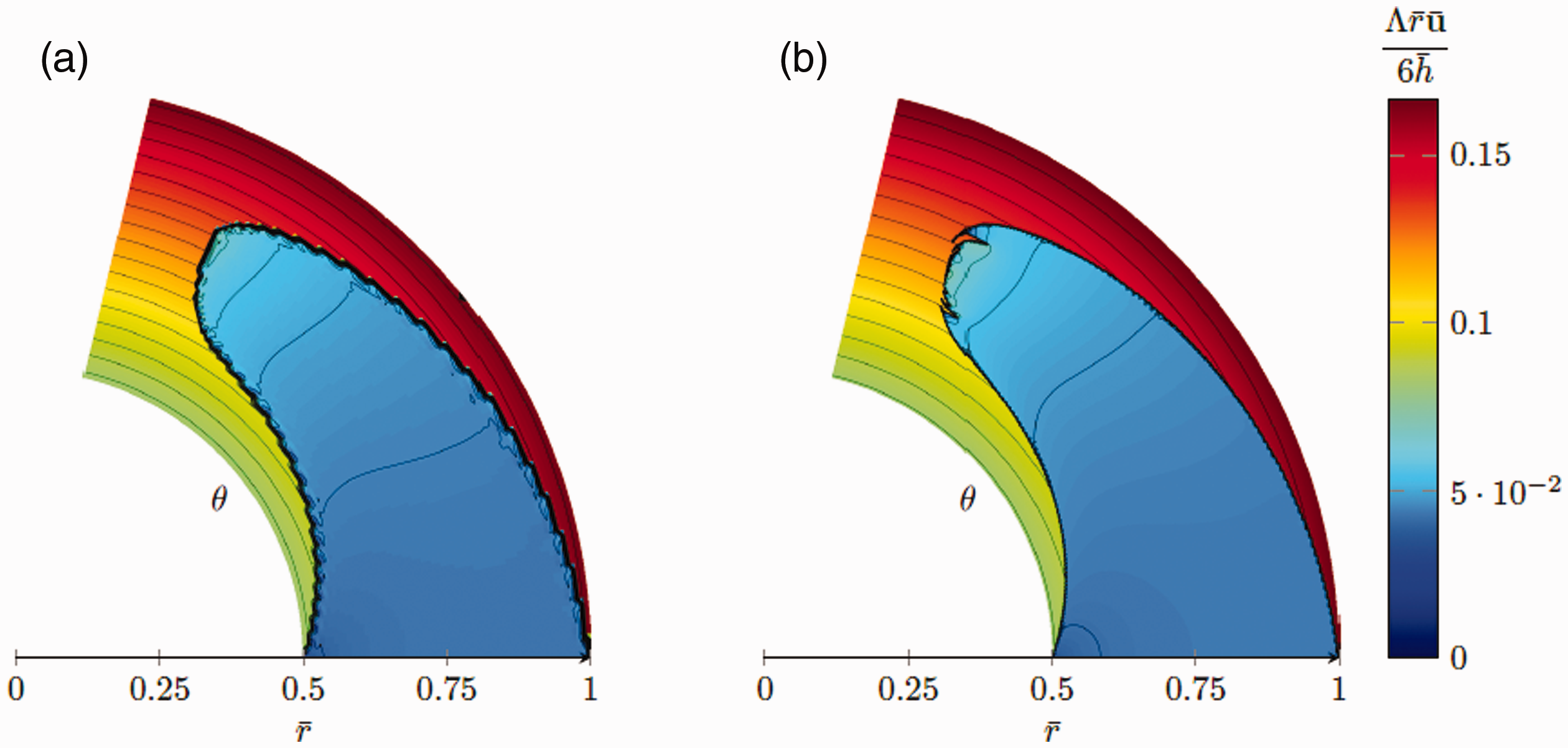
The Couette-flow shear stresses corresponding to the bearing geometries that maximises LCC for two differently refined meshes. (a)
Minimising COT
In this section, the results of minimising the COT, obtained using the same mesh resolutions i.e.
The bearing geometries that minimises the COT for two differently refined meshes, with contours levels. (a)
Figure 6 depicts the pressure distribution corresponding to the bearing geometries in Figure 5. It shows that the maximum pressure is found in the internal fluid entrapment, where it takes an almost constant value. Note, that the colorbar in Figure 6 has the same limits as in Figure 2, to show the relative absolute values. The figure also shows that, the pressure at the corners that have dropped to zero, effectively moving the boundary condition to a new edge.
The pressure distribution corresponding to the bearing geometries that minimises COF for two differently refined meshes. (a)
Figure 7 depicts the Poiseuille-flow shear stresses corresponding to the bearing geometries in Figure 5. It shows that the shear stresses on the sides of the pocket are close to zero, similar to the bearing geometry maximising the LCC. The bearing geometries minimising the COT does, however, an internal fluid entrapment and corner cut outs, which leads to that the Poiseuille-flow shear stresses vanishes in those regions. The shear stress in the reminder of the pocket is nonzero, but almost constant, and the trailing land exhibits a negative shear stress, one can notice that the blue negative area in Figure 7 which contains a moderately high shear stress than in Figure 3 since it will contribute to a lower FT.
The Poiseuille-flow shear stresses corresponding to the bearing geometries that minimises COF for two differently refined meshes. (a)
Figure 8 depicts the Couette-flow shear stresses corresponding to the bearing geometries in Figure 5. The shear stresses are distributed similarly as in the previous case, when the LCC was maximised. That is the positive shear stresses are found increasing at the flat land, and they increase radially. The figure shows that the internal fluid entrapment and corner cut outs, are beneficial in terms of decreasing Couette-flow shear stresses as well. The explanation for having a larger cut off at the outer corner is that the Couette-flow induced shear stresses increases with the speed and thus also with radius.
The Couette-flow shear stresses corresponding to the bearing geometries that minimises COF for two differently refined meshes. (a) E = 213 and (b) E = 217.
Minimising COT – Thrust washer
In this section, geometries which minimises the COT on thrust washers are presented. The thrust washers are constructed by a series of periodically repeating segments. The analysis will be focused on finding the COT-minimising geometries for thrust washers with varying numbers of segments. The thrust washer’s computational domain is identical to the computational domain of one of the thrust washers investigated by Yu and Sadeghi in Ref. 14 Figure 9(a) and (b) depicts are the optimal geometries, when the thrust washer is divided into 5 and 18 segments. The geometries in Figure 9(a) and (b) are similar, as they consist of distinctly separated pads, similar to the bearing geometries minimising the COT in the previous section. The difference from the geometries shown in Figure 5, is that a thin section of material has been removed from the leading edge, which in practise changes the periodic boundary condition to a Dirichlet boundary condition. These geometries are characterised as “Type 1” and Figures 12 and 13 depict the resulting LCC and FT for 2 to 18 segments, which all are of this type.
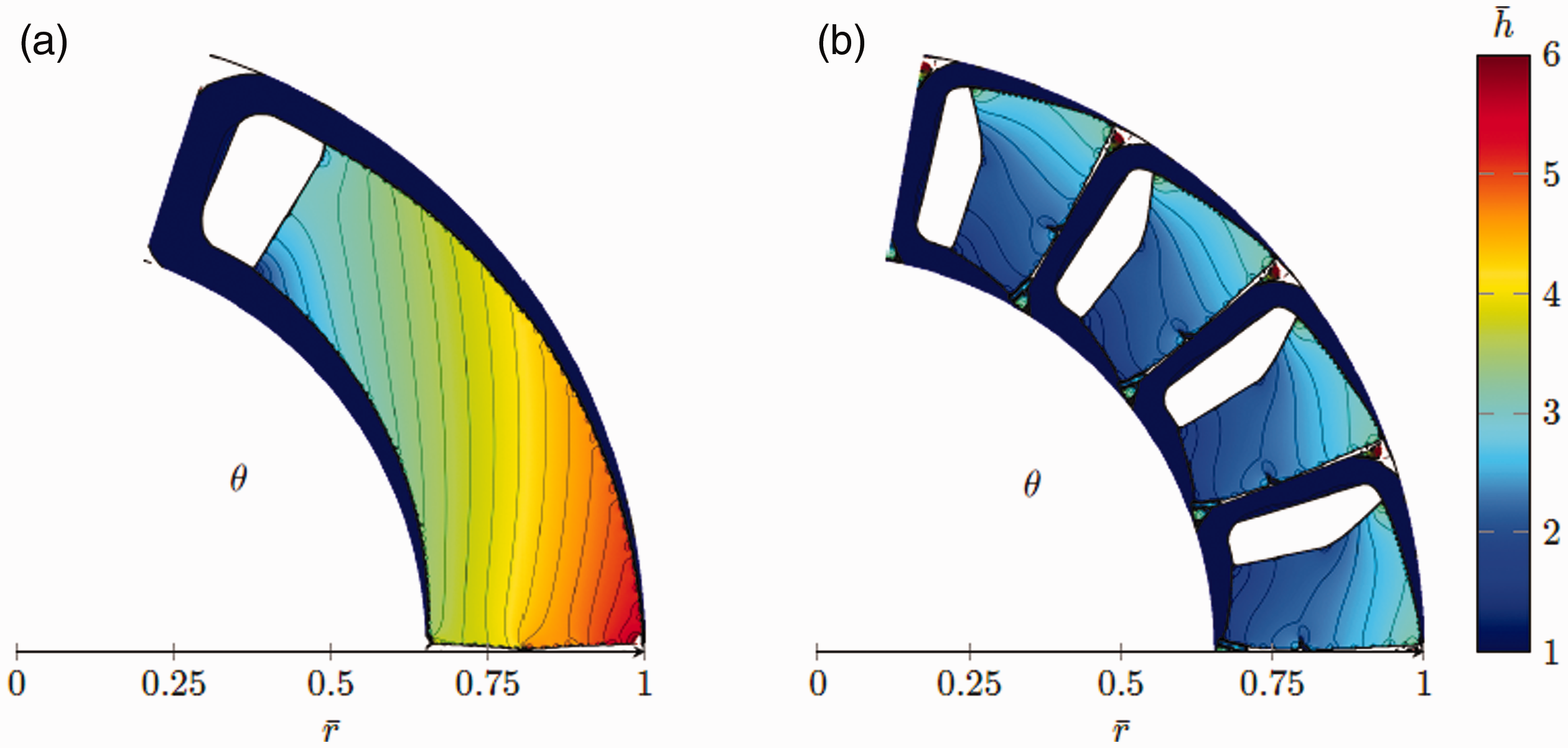
Bearing geometries of Type 1, that minimises the COT for 5 (a) and 18 (b). (a) 1 out of 5 segments and (b) 4 out of 18 segments.
Figure 10(a) depicts the optimum thrust washer geometry when it is constructed by 19 segments. It is clear that it is completely different to the optimum geometry with 18 segments, shown in Figure 9(b). This geometry features a quite wide circumferential groove, which stretches all around the thrust washer. Each segment has a load bearing area, which also functions as a valve. This is a more or less flat region with a fairly thin fluid film. With the “S-shaped” guide vane it is working as both an entrance for the fluid to the groove, and as a back-flow restriction. The geometry in Figure 10(a) is characterised as a Type 2 geometry. Depicted in Figure 10(b), is the optimal geometry when the thrust washer is constructed by 30 periodic segments. This geometry also features a circumferential groove, and in this case, there is a guide vane steering the flow over two separate regions. The first region is acting as a backflow restricting valve and it has an S-shaped vane, similar to the Type 2 geometry. While the first region has a more or less flat load bearing land, the second one has a gap that diverges towards the circumferential groove. The second backflow restricting valve and the small internal fluid entrapment area between the backflow restricting regions, separates the geometry in Figure 10(b) from the Type 2 geometry, and it is therefore characterised as a Type 3 geometry.
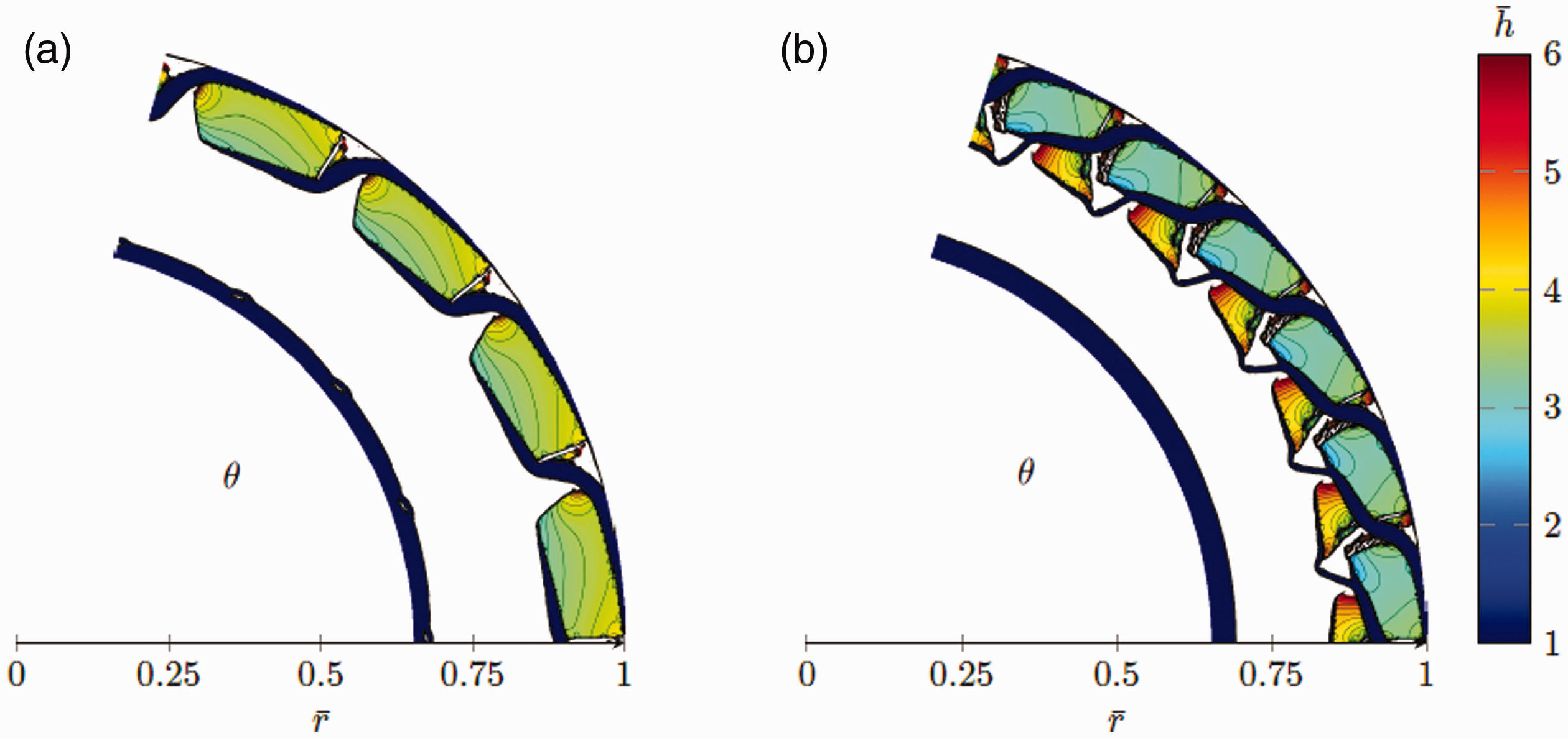
The bearing geometries that minimises the COT for 19 (a) and 30 (b) segments. The geometry in (a) is characterised as type 2 and in (b) is characterised as type 3. (a) 4 out of 19 segments and (b) 6 out of 30 segments.
Figure 11(a) depicts the optimum geometry when the trust washer is divided into 40 periodic segments, and it has characteristics of a Type 3 geometry. It differs from the geometry in Figure 10(b) in that it features 3 back-flow restrictions, which are separated by 2 small internal fluid entrapment areas. Figure 11(b) shows the optimum thrust washer geometry when 41 segments are used. This geometry has a distinct difference compared with the thrust washers with less segments, as it features two circumferential grooves and it is characterised as a Type 4 geometry. This Type 4 thrust washer has another circle of load bearing area with 2 back-flow restrictions, and an additional circumferential groove separating it from an intermediate ring with segments having 1 back-flow restriction.
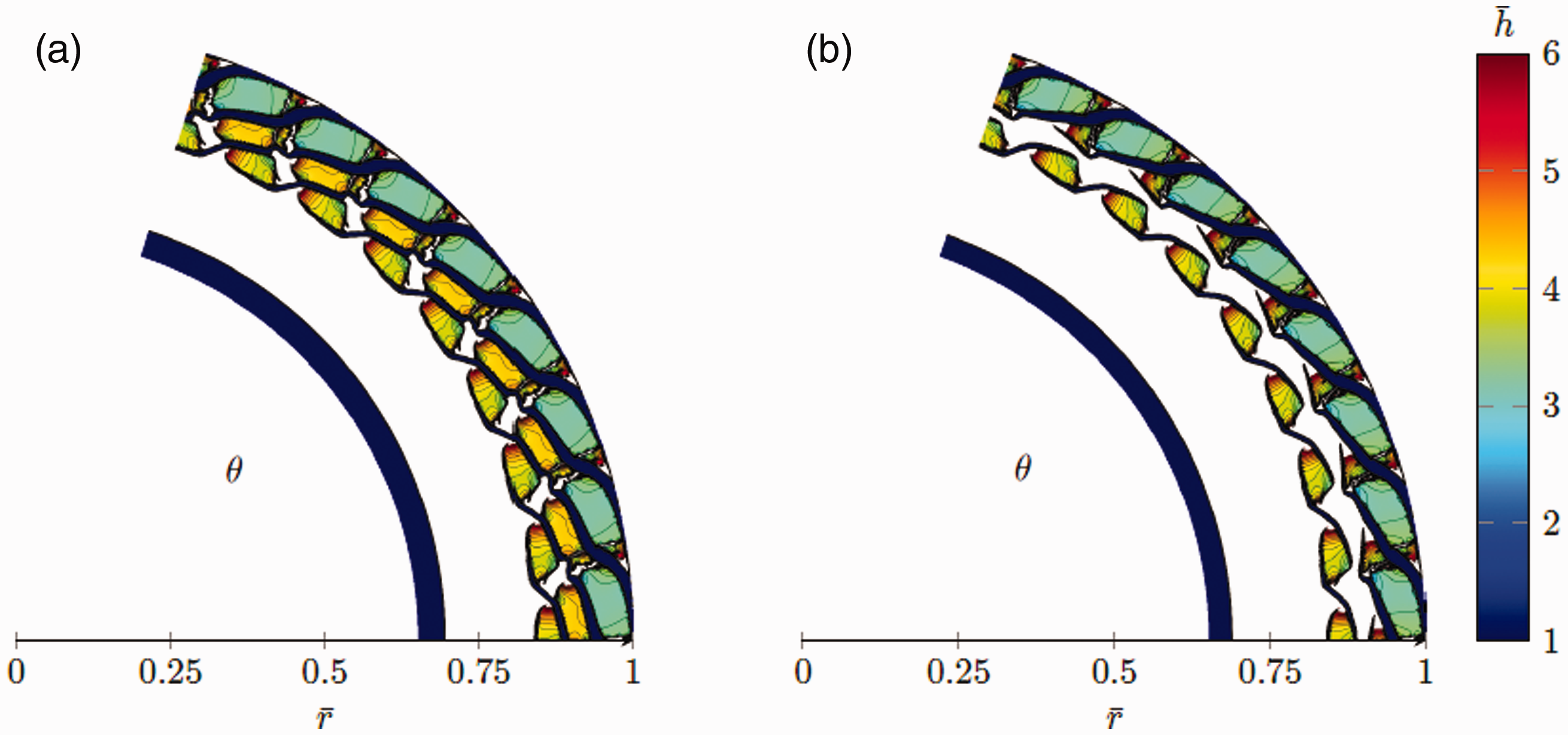
The bearing geometries that minimises the COT for 40 (a) and 41 (b) segments. The geometry in (a) is characterised as type 3 and in (b) is characterised as type 4. (a) 8 out of 40 segments and (b) 8 out of 41 segments.
The different geometrical types are connected to the number of segments that the thrust washer is divided into. The different types can also be recognised by looking at the LCC and the FT. Figure 12(a) depicts the relationship between the number of segments and the LCC. The different geometrical types be can be recognised as they are given different colours for a clearer distinction. The maximum LCC can be found when the thrust washer is divided into 5 periodic segments, and this geometry is depicted in Figure 9(a). The lowest LCC results for geometries of Type 2 and Type 4, and the reason is that a substantial portion of the available domain is made up by circumferential grooves. Figure 12(b) depicts the relationship between the number of segments and the FT. It can be seen that Type 1 geometries results in the highest FT, when the thrust washer is divided into more than 3 segments. The FT continues to increase and levels out at its maximum
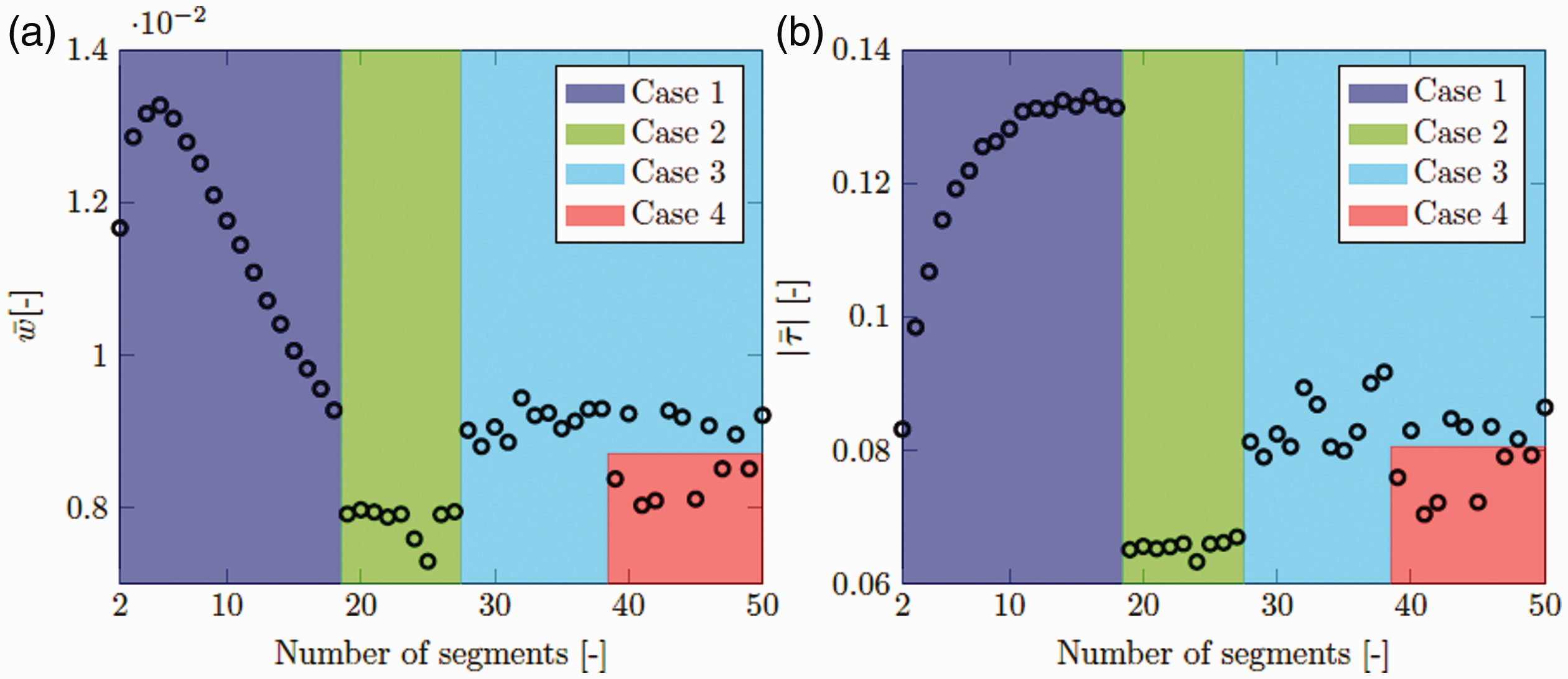
A visualisation of how the amount of periodic segments influences the LCC (a) and the FT (b). (a) Dimensionless load carrying capacity. (b) Dimensionless friction torque.
Figure 13(a) depicts the COT as a function of the number of segments. The figure shows that the lowest COT is obtained when the thrust washer is divided into using two periodic segments. As in Figure 12, the different types of geometries are given different colours to make it easy to distinguish between them. For the thrust washers of Type 1, the COT exhibits an almost linear dependence of the number of segments, and it is also the type with the largest COT when the number of segments is larger than 8 or so. For Type 2, 3 and 4 one can see a similar trend with the number of segments, but the increase is not as pronounced. Figure 13(b) shows the total number of mesh elements for the whole thrust washer, which is kept constant at
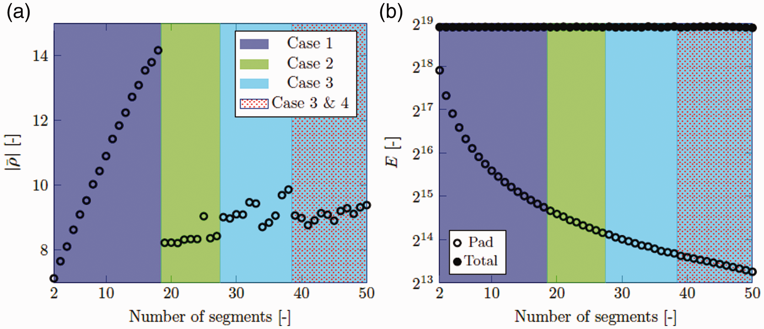
A visualisation of how the amount of periodic segments influences the COT and a visualisation of how the number of element per segment varies when the total number of elements is kept constant. (a) Dimensionless coefficient of friction torque. (b) Number of mesh elements.
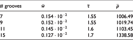
In Ref., 14 a conventional type of thrust washer, with grooves in the radial direction was studied. Some results from this study are shown in Table 1. The values are visual readings from diagrams in Ref., 14 and are therefore only quite rough estimates. The lowest LCC achieved by the COT-optimised thrust washer geometries obtained in the present work does, however, have more than 4 times higher LCC then the best performing thrust washer, with 7 grooves. The thrust washer with 7 grooves does also generate over 10 times more friction torque compared with the present Type 1 geometries with 10 to 18 segments, which have the highest friction torque of the optimal thrust washer geometries found in this work. As a result of the large difference in LCC and FT compared to the optimal thrust washer geometries, the COT for the thrust washer with 7 grooves is substantially higher than the COT-values for the present optimal thrust washer geometries.
Some results for the radial-groove thrust washers studied in Ref. 14
Concluding remarks
The performance of hydrodynamically lubricated axial thrust bearings, operating under incompressible lubrication, was studied by means of a Reynolds equation based model implemented within the Finite Element (FE)-based simulation software COMSOL Multiphysics®. The Optimization Physics Interface inside the program, was set to optimise the thrust bearing geometries using the globally convergent method of moving asymptotes, developed in Refs.10,11 The objectives were to find the geometries that either maximises the Load Carrying Capacity (LCC), minimises the Coefficient of friction Torque (COT) and, additionally, to find thrust washer geometries that minimises the COT. A mesh convergence study was conducted for the LCC and the COT objectives, even though the methodology has already in Refs.13,15 been proven to give convergence. The bearing geometries maximising the LCC obtained when using coarser meshes, were observed to closely resemble the pocket bearing that was found in Ref. 7 However, when the mesh was refined, shark-fin like features appeared in the transition zone between the pocket’s trailing edge and the flat land, similar to the ones found by the authors in the present work in Ref. 15 The shark fins were also found to contribute to an increased LCC. The geometries minimising the COF were also of pocket type, but without shark fins at the back end of the pocket. Moreover, when the mesh was refined, an internal fluid entrapment region appeared there instead, and the corners of the flat trailing edge land were also removed by the optimisation procedure.
A study on minimising the COT for a thrust washer divided in to a different number of segment was also performed. Four differently characteristic types of geometries were identified when varying the number of segments between 2 and 50. Thrust washer geometries of Type 1, closely resembled the axial bearing geometry with
The results show that the present method can be used to obtain bearing geometries with excellent performance, perhaps even the best known until now. For the coarser mesh, the present method produces results that to the eye are identical to geometries available in the literature, but with mesh refinements the present method renders geometries that are different and that outperform those. The present method also provides us with new bearing geometries that minimise the COT. Especially interesting are the thrust washer geometries, as they made up by a few simple structures where the film thickness takes only a few distinct values. This support the possibility to actual realisation of these geometries.
All in all, the findings presented herein, suggest that the present approach could be used to facilitate the design of hydrodynamically lubricated axial thrust bearings, under incompressible lubrication as long as the lubrication thereof can be assumed to be incompressible.
Footnotes
Declaration of Conflicting Interests
The author(s) declared no potential conflicts of interest with respect to the research, authorship, and/or publication of this article.
Funding
The author(s) disclosed receipt of the following financial support for the research, authorship, and/or publication of this article: This work was supported by Vetenskapsrådet (2019-04293).