
Abstract
The search for the optimal bearing geometry has been on for over a century. In a publication from 1918, Lord Rayleigh revealed the infinitely wide bearing geometry that maximises the load carrying capacity under incompressible flow, i.e. the Rayleigh step bearing. Four decades ago, Rohde, who continued on the same path, revealed the finitely wide bearing geometry that maximises the load carrying capacity, referred to as the Rayleigh-pocket bearing. Since then, the numerical results have been perfected with highly refined meshes, all converging to the same Rayleigh-pocket bearing. During recent years new methods for performing topology optimisations have been developed and one of those is the method of moving asymptotes, frequently used in the area of structural mechanics. In this work, the method of moving asymptotes is employed to find optimal bearing geometries under incompressible flow, for three different objectives. Among the results obtained are (i) show new bearing geometries that maximise the load carrying capacity, which performs better than the ones available, (ii) new bearing geometries minimising the coefficient of friction and (iii) new bearing geometries minimising the friction force for a given load carrying capacity are presented as well.
Keywords
Introduction
The bearing geometry is of highest importance for optimal performance, such as the film thickness and efficiency of the bearing. Indeed, an increased load carrying capacity (LCC) will result in an increased film thickness, thereby decreasing the risk of wear. In turn, less wear increase useful life and the need replacements, thereby reducing costs. A reduced coefficient of friction (COF) decreases friction losses, thereby improving the efficiency of the bearing, and ultimately increasing the productivity or decreasing resources needed for running the system, thereby also reducing costs.
The quest of finding the optimal bearing geometry started decades ago with an early publication by Rayleigh, dating back to 1918. 1 By application of calculus of variation, Rayleigh analytically optimised the bearing geometry of an infinitely wide slider operating under incompressible flow with the objective of maximising the LCC. The result was a step-bearing geometry, nowadays referred to as the Rayleigh step bearing. The drive of finding the optimum bearing geometry continued and half a decade later, Maday developed a new method 2 and optimised 3 the geometry of a bearing operating under (compressible) ideal gas flow. The resulting bearing geometry that Maday found, also featured the characteristic and flat trailing land of the Rayleigh step bearing, but with and but with a converging section instead of a flat leading land. Rohde 4 was the first one to consider a new type of objective when optimising the bearing geometry, with the goal set to find the bearing geometry that under incompressible flow minimises the COF. The result was a bearing geometry with a flat leading- and trailing lands, but with a tapered instead of the vertical step in the Rayleigh step-bearing geometry. Later, Auloge et al. 5 optimised a bearing geometry for a non-Newtonian fluid flow, this resulted in a step-bearing geometry, with the step location and height different from the Rayleigh step bearing. Boldyrev 6 later optimised a bearing geometry subjected to a compressible ideal gas flow using a model with periodic boundary conditions, the result showed similarities with the one found by Maday. 3 These findings on infinitely wide sliders are especially interesting where application is suitable, i.e. where no side leakage occurs.
For many applications, the side leakage is too large to be disregard and optimisation has naturally shifted focus to finitely wide sliders. Kettleborough 7 presented a finitely wide pocketed geometry, performing well in terms of LCC. In the same article he also presented a geometry with an internal fluid entrapment, which reduces the shear stresses in the fluid film. Rohde, 8 optimised parameterised pocket bearings with piece-wise constant film thickness for maximised LCC, while considering different types of pockets. A few years later, Rohde and McAllister continued the work on optimising for maximum LCC using an FDM approach, 9 the method allowed every discrete point on the mesh to take any value of the film thickness, independently. They found the bearing geometry that maximise the LCC under incompressible flow, i.e. the Rayleigh-pocket bearing. Robert 10 optimised bearing geometries with piece-wise constant film thickness operating under ideal gas flow. The results were pocketed type of sliders. The same year, Boldyrev et al. 11 maximised the LCC, considering ideal gas flow. This resulted in a pocketed type of bearing, having an increased tapering on the leading edge compared to the Rayleigh-pocket bearing. Later, Buscaglia et al. 12 found the bearing geometry that maximises LCC for a bearing exhibiting Burgdorfer gas flow, 13 where the method was also demonstrated to work on journal bearings. Buscaglia et al. 14 implemented a new method for optimising bearing geometries for maximum LCC and demonstrated its applicability by replicating the work by Rohde and McAllister. 9 The result was obtained using a mesh having about 50 times more elements than in 1976, 9 the generated optimal bearing geometry was smoother and the LCC was also slightly increased both as a result from the increased mesh resolution. Just a couple of years later, van Ostayen 15 developed a new method for obtaining the optimal bearing geometry. As a benchmark, he too replicated the work by Rohde and McAllister, 9 but with a mesh having 750 times more elements. As expected, he found that with a refined mesh the LCC further increased. It was also demonstrated that the method could be used to obtain bearing geometries for different objectives and changes made in the computational domain. A few years later, Fesanghary and Khonsari found the axial bearing geometry that maximises the LCC for an incompressible fluid. 16 Results based both on having a piece-wise constant- and a variable film thickness were shown, and the geometries found exhibited a cylindrically shaped Rayleigh-pocket bearing characteristics. The aforementioned works1–14,9,15,16 show that there are various methods for fining optimal bearing geometries.
Topology optimisation comprises a class of methods within the field of structural mechanics, frequently used for obtaining light weight structures while minimising strain energy. An advantage with topology optimisation is that the control variable can be more or less arbitrary defined, when maximising or minimising an objective function. In the field of tribology and more specifically in the branch of hydrodynamically lubricated slider bearings, topology optimisation methodology has not been applied that frequently. There are several different topology optimisation methods, e.g. in the field of structural mechanics Jakiela et al. 17 demonstrated the use of a genetic algorithm, and Di Cesare and Domaszewski 18 used a particle swarm optimisation method, both considering the same type of problem. The topology optimisation method globally convergent method of moving asymptotes (GCMMA) is available in COMSOL Multiphysics® 19 and was developed by Svanberg;20,21 this method can be used in structural analysis and recently, Kalliorinne et al. 22 used it to optimise the bearing geometry of infinitely wide sliders for maximum LCC as well as minimum COF. Kalliorinne et al. numerically replicated the works in literature1,3,4 verifying a new method for obtaining existing optimal bearing geometries, and used it to find the bearing geometries that minimise the COF when exhibiting compressible ideal gas flow. They also unveiled the bearing geometries that maximise the LCC and the bearing geometries that minimises the COF, for fluids exhibiting a constant bulk modulus behaviour. In parallel an analytic approach was performed by Almqvist et al. 23 for fining the bearing geometries that maximises the LCC for fluids exhibiting a constant bulk modulus.
It has come to the authors’ knowledge that there is yet no solution for the finite-bearing geometry that minimises the COF under incompressible flow. The authors have also discovered that when applying GCMMA method for optimising finite bearing geometries under incompressible flow, obtained bearings’ geometries maximising LCC outperform previously found bearing geometries. The obtained bearing geometry also has substantial differences to the previous bearing geometry. Here optimisation of bearing geometries which is subject to a incompressible flow formulated as the classical Reynold’s equation using the GCMMA method inside COMSOL Multiphysics,® 19 the objective will be to either maximise the LCC or minimise the COF.
Governing equations
In this work, the Reynolds equation is adopted to govern the thin film flow of an incompressible fluid under steady conditions, inside a rectangular 2D computational domain Ω bounded by


The computational domain can be non-dimensionalised as


The FF

Now the scaled COF

Explicitly, it can be expressed as

Description of the numerical approach
Prior to this study, Kalliorinne et al.
22
used the finite element (FE) software COMSOL Multiphysics® to conduct topology optimisations on infinitely wide sliders’ geometries. In Kalliorinne et al.,
22
the Reynolds equation was modelled using the coefficient form partial differential equation physics interface, and the GCMAA-based optimisation algorithm was setup inside the optimisation physics interface, with the film thickness as the control variable. Here, the governing equation (5) and the optimisation will be setup in a similar way. To this end, the control variable will be specified as the dimensionless film thickness

The optimisation starts from a specification of an initial bearing geometry


Note that the symmetry needs to be considered before calculating the LCC and the FF, as specified by equations (6) and (7), respectively.
Results and discussion
Next, the results will be presented and discussed. It starts with optimisation for maximum LCC, then for minimum COF, followed by a comparison between the different objectives. In the end, results for minimising the FF are presented. In the next subsection, results consisting of bearing geometries, pressure distributions and shear stresses from Poiseuille- and Couette flow, for three different meshes when maximising the LCC will be presented. In the subsequent subsection, results from minimising the COF will be presented in a similar way. It will be continued in the following subsection, by a comparison of using the two different objectives, i.e. maximising LCC and minimising COF, presented as a mesh convergence study. In connection to this results from the previous works,9,14,15 where maximisation of LCC as been addressed, are also included in the discussion. Lastly, in the final subsection, results for minimising the FF, for three markedly different choices of LCC, will be presented.
Maximising the LCC
Here, the results from maximising LCC are presented. The results are partitioned into three differently refined meshes with number of elements E, i.e. The bearing geometries that maximises the LCC for three meshes with increasing resolution from left to right. (a) 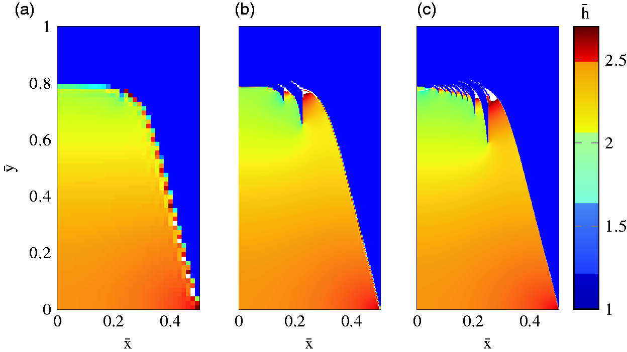
Depicted in Figure 2 are the same bearing geometries as in Figure 1, but here with contour lines included to elucidate upon the height variations within the pocket. Here we can see that the mesh refinement only marginally affects the large scale geometry features of the pocket. When looking at the region where the shark fins are located there is, however, significant differences. Indeed, expect for the fine details of the shark fins themselves, the film thickness increases within the shark fins as well. Moreover, the optimal shape actually assumes the upper limiting value ( The bearing geometries that maximises the LCC for three meshes with increasing resolution from left to right, with contours levels. (a) 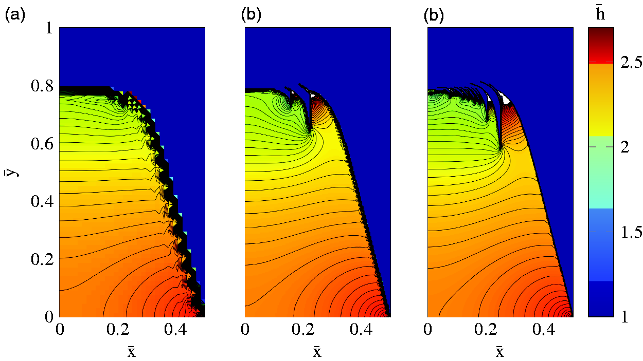
Depicted in Figure 3 are the pressure distributions corresponding to the geometries in Figures 1 and 2. The figure shows that, the maximum pressure increases as the mesh is refined, and the contribution from the shark fins can clearly be seen as well.
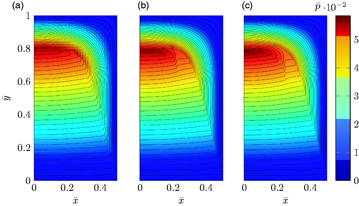
Figure 4 depicts the Poiseuille-flow contribution to the shear stress distributions, i.e. the contribution from the first term in the expression for the dimensionless FF (7), for the bearing geometries in Figures 1 and 2. As expected, the largest contribution comes from the pocket, where the Poiseuille-flow shear stress also takes a more or less constant value. Moreover, it shows that the shear stress at the trailing edge is negative, as the fluid here is pushed out by the pressure in the same direction as the speed of the slider. The large negative values act over a very small area around the edges of the shark fins.
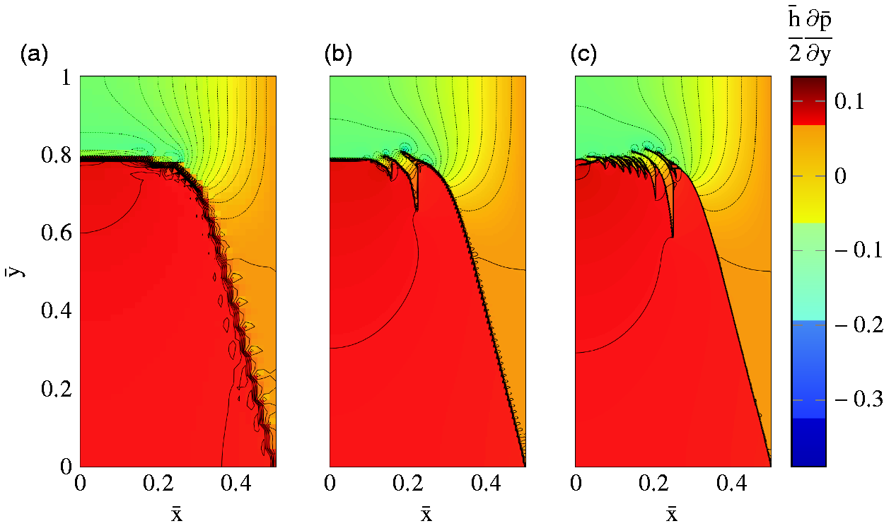
Figure 5 depicts the Couette-flow contribution to the shear stress distributions, i.e. the contribution from the second term in the expression for the dimensionless FF (7), for the bearing geometries in Figures 1 and 2. The figure clearly shows that the major part of the Couette-flow shear stress component is generated at the flat trailing land area. It is also clear that the Couette- dominates over the Poiseuille flow, when comparing the amplitude of the corresponding shear stress distributions.
Minimising the COF
Here, the results from minimising the COF are presented. The results are given for the same three mesh resolutions that were used when maximising the LCC, i.e. The bearing geometries that minimise the COF for three meshes, with increasing resolution from left to right. (a) 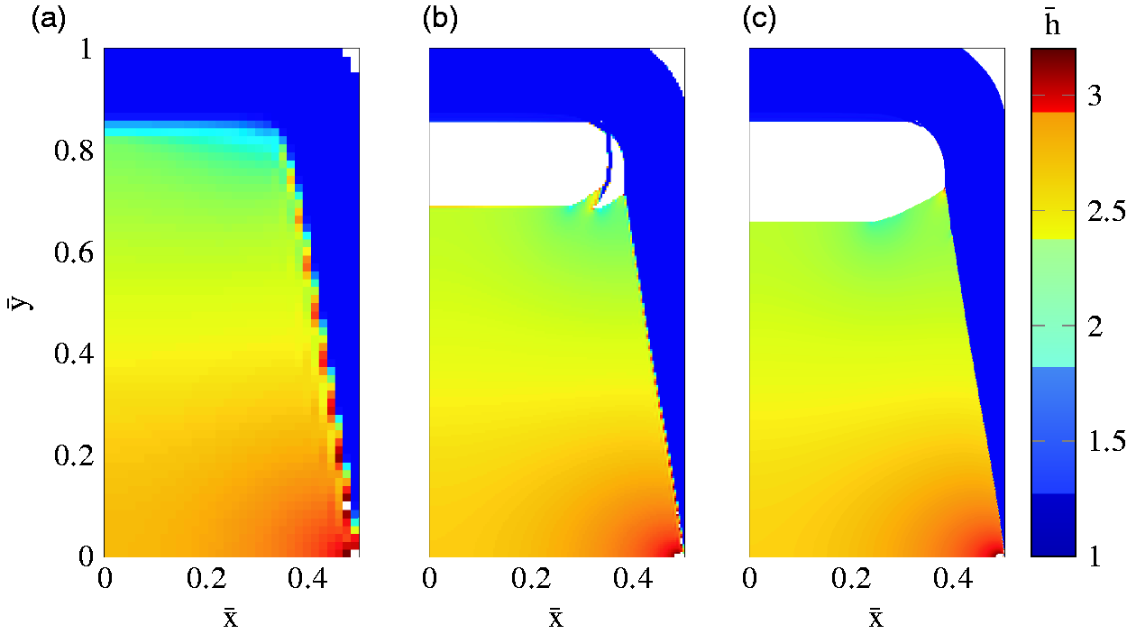
The bearing geometries which are minimising the COF are also depicted in Figure 7, but here with height contours added. When comparing the geometry in Figure 7(a) (obtained using the coarsest mesh) with geometries in Figure 7(b) and (c), one can see that there are less contours crossing the y-axis in the former, which exhibits a tapered type of pocket without the internal fluid entrapment area at the back end. This tells us that the pocket becomes less steep, as the internal fluid entrapment area develops. For the intermediate mesh resolution, The bearing geometries that minimise the COF for three meshes with increasing resolution from left to right, with contours levels. (a) 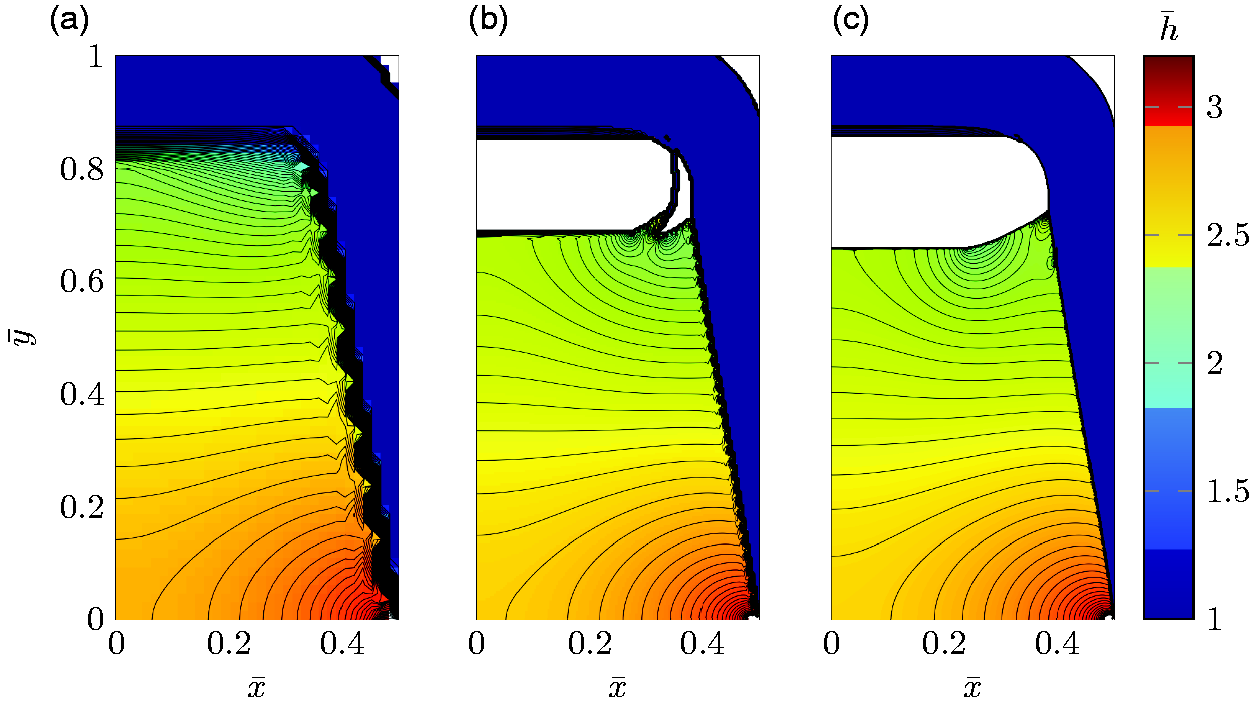
The pressure distributions corresponding to the geometries in Figures 6 and 7 are depicted in Figure 8. What stands out the most here is the area of the uniform pressure which appears as the internal fluid entrapment region develops when increasing the mesh resolution. The effect associated with the material removal of the upper corners can also be seen. It is expressed by the pressure being zero there, thus effectively moving the boundary condition to the edge of the cutout region.
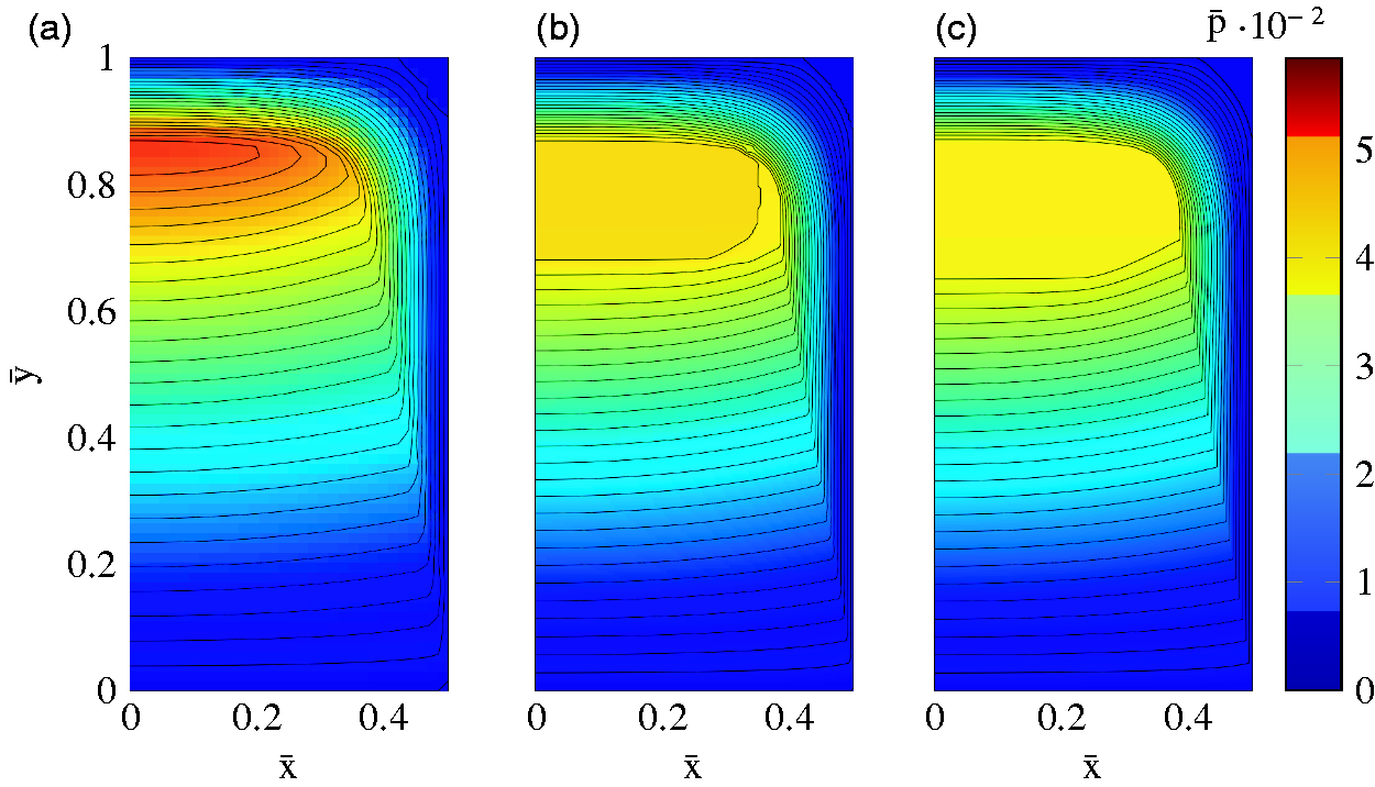
Figure 9 depicts the Poiseuille-flow shear stress distributions for the bearing geometries in Figures 6 and 7. As for the bearing geometries maximising LCC, the largest contribution comes from the pocket, and the Poiseuille-flow shear stress takes a more or less constant value for the COF minimised geometries as well. Moreover, it shows that the shear stress at the trailing edge is negative here too. Here the benefits of having an internal fluid entrapment area are also shown. This is demonstrated by the shear stress being zero, as a result of that the pressure derivative is zero. This is also true for the corners, where materials have been removed.
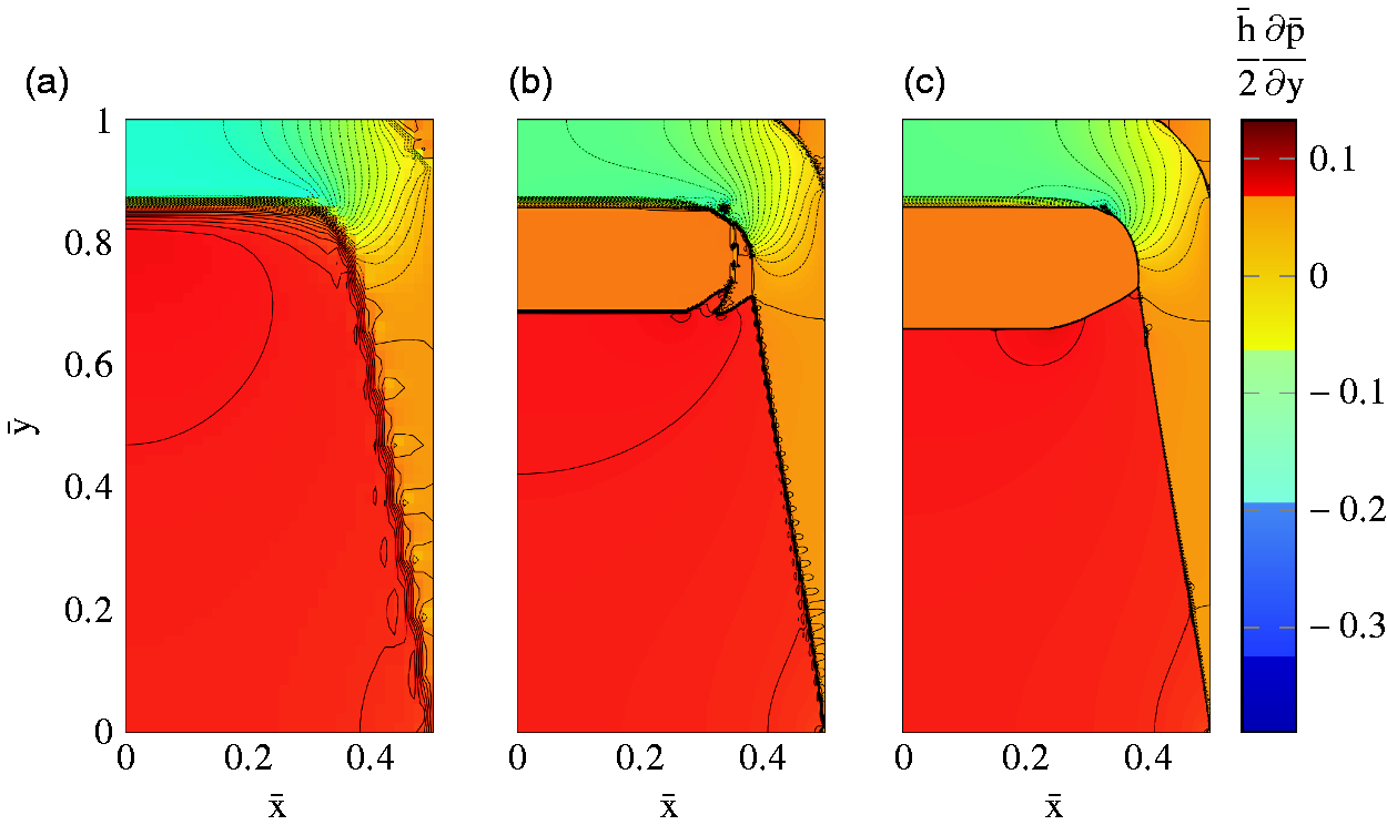
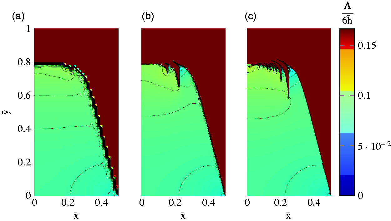
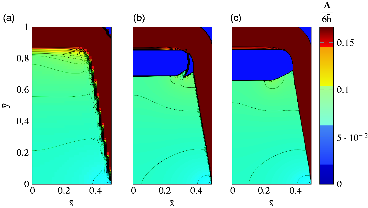
Figure 10 depicts the Couette-flow shear stress distributions for the bearing geometries in Figures 6 and 7. The figure clearly shows that the major part of the Couette-flow shear stress component comes from the flat land. Having the internal fluid entrapment area and the material removal at the corners are clearly shown beneficial here, as the Couette-flow shear stress almost vanishes, due to the substantial film thickness increase.
Comparison between LCC and COF as objectives
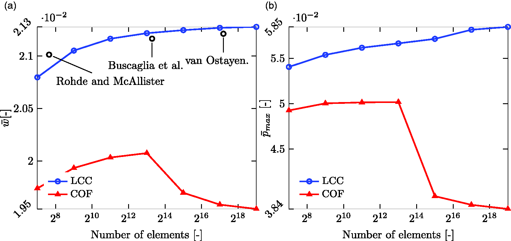
In this section, the performance of the bearing geometries will be presented as a mesh-refinement study. A comparison will be made between results obtained with geometries that either maximise the LCC or minimise the COF. Results available in the literature will also be included in the comparison. The results depicted in Figure 11(a) are the LCC of the bearings optimised for maximum LCC – blue line with circle markers and minimum COF – red line with triangular markers. In addition, results presented in the previous works,9,14,15 where maximisation of LCC were performed with other methods, are also included – black circles. The optimisation method used by Rohde and McAllister
9
does result in a better performing bearing when the same amounts of elements are used. However, when the mesh is further refined, the LCC of the bearing geometry maximising LCC eventually surpasses all the previous works. To be noted, is that a uniform mesh was used in this study, while van Ostayen
15
was using an adaptive meshing technique, expected to perform better, since it has the ability to resolve critical areas of the mesh more accurately. With similar element count, the present method does, however, render a geometry that performs better. Looking at the LCC for the bearing geometry minimising the COF, it is clear that the appearance of the internal fluid entrapment area results in a significant decrease in the LCC. The maximum pressures, as functions of the number of mesh elements, obtained with each of the optimisation setups are depicted in Figure 11(b). The maximum pressure for the both LCC-maximising and the COF-minimising geometries shows similar trends as the LCC in Figure 11(a). That is, the LCC-maximising geometries give rise to an increased maximum pressure as the mesh is refined, and the effect of the formation of the internal fluid entrapment area is also clearly visible in the results for the COF-minimising geometries.
A comparison between the performance of the absolute FF and the COF for geometries obtained with optimisation for LCC and COF as objectives is depicted in Figure 12. As in Figure 11, the results are presented as a mesh-refinement study. Figure 12(a) shows that no obvious mesh dependence of the absolute FF can be observed for the geometries maximising the LCC (blue line with circle markers). The absolute FF for the bearing geometries minimising the COF does, however, decrease when the mesh is refined. This is expected, and due to the formation of the internal fluid entrapment region. In Figure 12(b), the mesh dependence of the predicted COF is shown, and here both the LCC-maximising and the COF-minimising geometries exhibit a decreasing trend. Again, the effect of the formation of the internal fluid entrapment region is clearly visible in the results for the COF-minimising geometries.
Showing the impact on 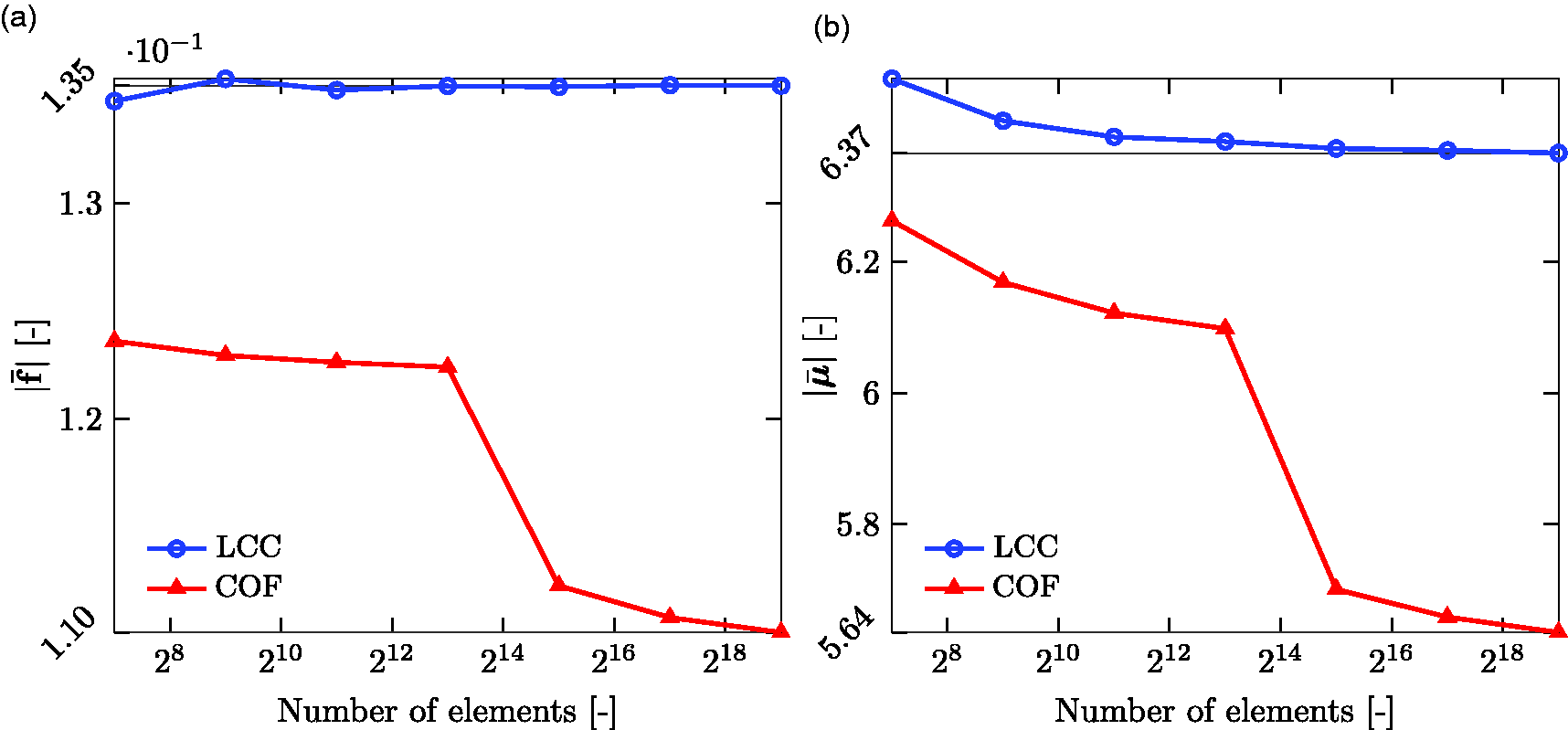
Results obtained when optimising for maximum LCC.
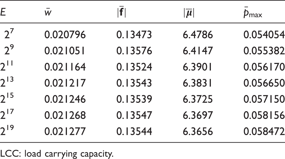
LCC: load carrying capacity.
Results obtained when optimising for minimum COF.
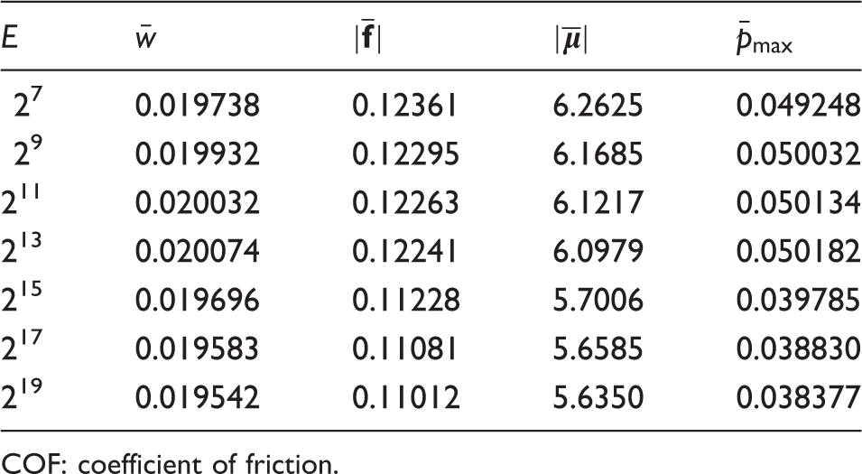
COF: coefficient of friction.
Minimising the friction force
The results obtained when minimising the FF are presented here. Three markedly different values of the dimensionless LCC, i.e. The bearing geometries that minimise the FF with three values of LCC, decreasing from left to right. (a) Results obtained when optimising for minimum friction force, for three different choices of LCC. LCC: load carrying capacity.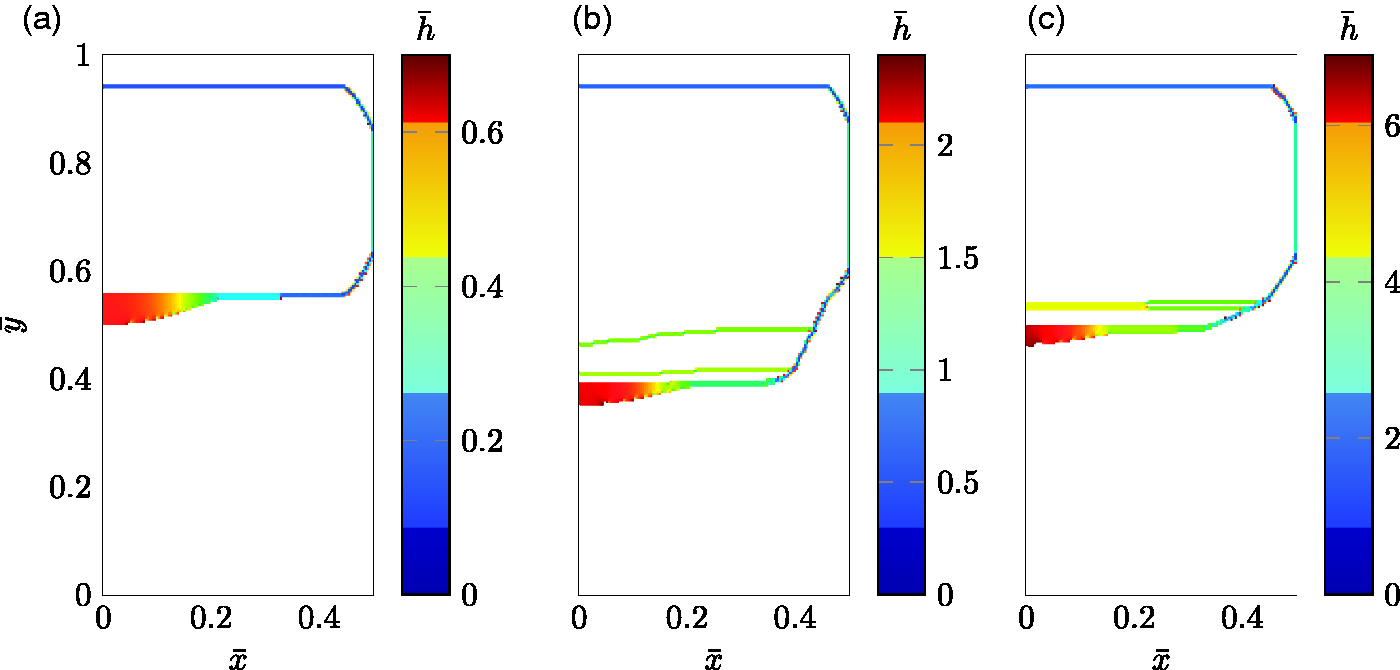
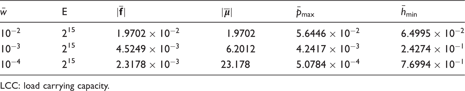
Figure 14 depicts the pressure distributions corresponding to the bearing geometries in Figure 13. The figure shows that the pressure inside the internal fluid entrapment region is constant and this is also where the absolute majority of the LCC is generated. As in the case of the COF minimisation, the material removal effectively moves the pressure boundary conditions to the apparent bearing geometry.
The pressure distribution corresponding to the bearing geometries depicted in Figure 13, which minimise the FF. The LCC decreases from left to right. (a) 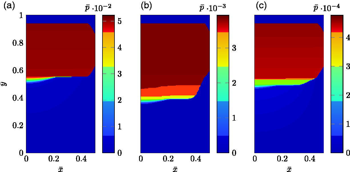
Figure 15 depicts the Poiseuille-flow shear stress distributions corresponding to the bearing geometries in Figure 13. From each of the depictions, it can be seen that the shear stress is zero on the majority of the domain. However, the leading edge of the apparent bearing has a positive- and the trailing edge a negative contribution, to the shear stress.
The Poiseuille-flow shear stresses corresponding to the bearing geometries depicted in Figure 13, which minimise the FF. The LCC decreases from left to right. (a) 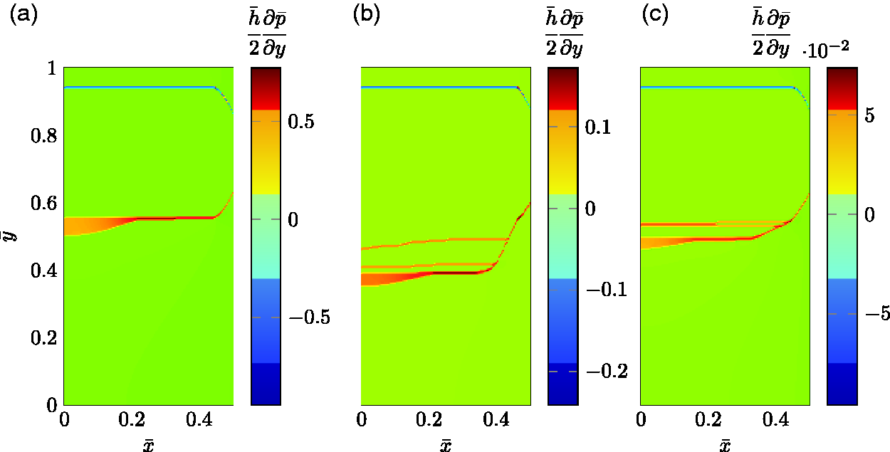
Figure 16 depicts the Couette-flow shear stress distributions corresponding to the bearing geometries in Figure 13, which are non zero on the land of the apparent bearing. It can also be seen that the trailing land has a larger contribution to the shear stress component than the leading edge. The largest Couette-flow shear stress is, however, observed at the sides of the narrow land, where the film thickness is the thinnest.
The Couette-flow shear stresses corresponding to the bearing geometries depicted in Figure 13, which minimise the FF. The LCC decreases from left to right. (a) 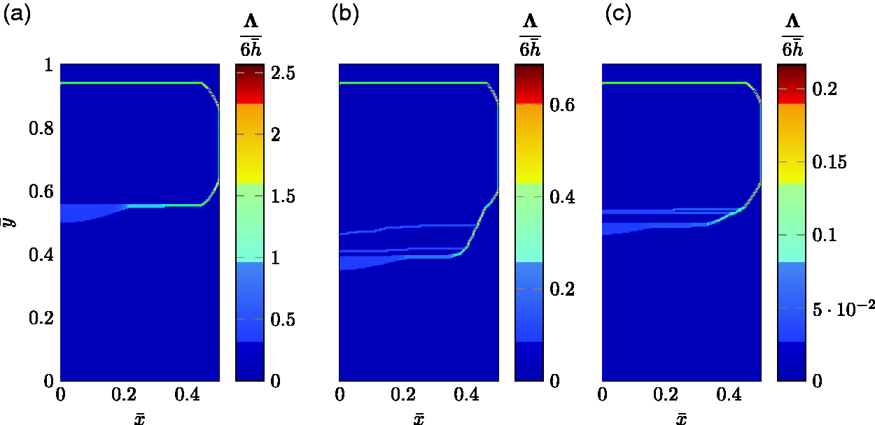
The performance data obtained from the bearing geometries minimising the FF are shown in Table 3.
Concluding remarks
The performance of hydrodynamically lubricated bearings operating under incompressible flow was studied by means of a Reynolds equation based model implemented within the FE-based simulation software COMSOL Multiphysics®. The optimisation physics interface inside the program was set to optimise the bearing geometries using the globally convergent method of moving asymptotes, developed in literature.20,21 The objectives were to find the bearing geometry that either maximises the LCC, minimises the COF or minimises the FF. Mesh convergence studies were conducted for the LCC and the COF objectives. The bearing geometries maximising the LCC obtained when using coarse meshes were observed to closely resemble the Rayleigh-pocket bearing previously addressed in references.9,14,15 However, when the mesh was refined, shark-fin like features appeared in the transition zone between the pocket’s trailing edge and the flat land. The shark fins were also found to contribute to an increased LCC. The geometries minimising the COF were also of pocket type, but without shark fins at the back end of the pocket. However, when the mesh was refined, an internal fluid entrapment region appeared there instead, and the corners of the flat trailing edge land were also removed by the optimisation procedure.
A study on minimising the FF with the LCC prescribed by three markedly different values was also performed. The results were three optimum bearing geometries, that all featured internal fluid entrapment regions. However, the land of the bearing turned out to be extremely narrow with a very limited amount surface area, thus not suitable in practice. The knowledge gained from this part of the work, is that minimisation of FF with a prescribed LCC, requires a lower limit for the film thickness. This would thereby generate bearing geometries which would depend on this lower limit, thus it would not be as generally applicable as the LCC-maximising- and the COF-minimising geometries.
It has been shown that the present method can be used to obtain bearing geometries with better performance than the bearing geometries previously found. For very rough meshes the present method produces results that to the eye are identical to the geometries available in the literature, but even with fairly small mesh refinements the present method produces geometries that are different than those. The present method also provides us with new bearing geometries that minimise the COF.
All in all, the findings presented herein, suggest that the present approach could be used to improve the design of hydrodynamically lubricated bearings under incompressible flow.
Footnotes
Acknowledgements
The authors would like to thank all the reviewers for their thorough perusal and valuable comments.
Declaration of Conflicting Interests
The author(s) declared no potential conflicts of interest with respect to the research, authorship, and/or publication of this article.
Funding
The author(s) disclosed receipt of the following financial support for the research, authorship, and/or publication of this article: We also want to acknowledge the financial support from the Swedish Research Council (Vetenskapsrådet), via the last authors’ project entitled Multiscale topological optimisation for lower friction, less wear and leakage, with registration number 2019-042934.