
Abstract
In wearing contacts, a part of the wear debris is trapped between the surfaces, creating a wear debris bed. Many researchers report such beds providing a degree of protection against further wear. It was hypothesized, that in an annular contact, the level of debris entrapment increases with the width of the annulus resulting in decrease in wear. To test this hypothesis, two series of experiments using EN1A steel and 6082T6 aluminium alloy annuli, measuring 1, 2 and 4 mm wide were carried out. When steel was used, there was no clear correlation between ring width and total mass loss or steady-state wear rate. When aluminium was used, wear decreased with the ring width according to both metrics. This behaviour appears to correlate with worn surface roughness, suggesting worn surface roughness to be a parameter controlling debris entrapment.
Introduction
The goal of experimental wear studies is to reveal material properties under controlled laboratory conditions which may then be used to infer the rate of wear in complex prototypical problems. Unlike friction, where the pointwise value may be inferred from a global sliding test, wear is clearly not independent of geometry. Although approximations of real-world contacts are used in some studies,1–3 the most common configurations for wear tests remain the pin-on-flat and ball/cylinder-on-flat arrangements4,5 which share the property of the contact patch being fixed relative to one body, but experiencing motion much greater in extent than its own size in the other. Thus, material being worn is freely exposed and there is little debris entrapment. On the other hand, many practical wear problems involve fretting contacts which experience movements that are small as a fraction of the size of the contact. Such contacts may entrap wear debris to a significant extent. At present, it is unclear how to infer the wear rate in a fretting configuration of one geometry from a test in a different geometry.
It was Godet 6 who first recognized the importance of debris in controlling wear and who referred to it as a ‘third body’. Debris entrapment has great influence on wear, as demonstrated by a number of studies which observed that wear increases if the ejection of wear debris is encouraged (see Hintikka et al. 7 and Leheup and Pendlebury 8 on annular contacts (Lemm et al. 5 and Fouvry and Merhej 9 ), on cylinder-on-flat contacts). Conversely, Fillot et al. 10 demonstrated that wear can be effectively suppressed by inhibiting debris ejection. The idea that wear debris entrapment may lead to reduced wear is further articulated in Hayes and Shipway, 11 Warmuth et al. 12 and Jiang et al. 13 and appears to be widely accepted. However, it is not clear exactly which factors govern the entrapment of debris. Zmitrowicz 14 explained the phenomenon of entrapment as a consequence of disparity between the characteristic length of the contact and the much smaller characteristic length of the debris particle. Given this explanation, it is intuitively expected that entrapment will depend on the length of the particle ejection path. Contacts forcing the particles to travel longer distances are expected to entrap debris to a greater degree. However, in the majority of published studies where debris entrapment was varied by changing geometry (larger/smaller radii of balls and cylinders,5,9 radial notches in annuli, 7 etc.) the geometrical change also influenced other wear parameters, such as the distribution of contact pressure, the local stresses or the ratio of contact width to the imposed displacement. These changes make it difficult to attribute the observed effects conclusively to geometric factors.
It is desirable to develop a test that could isolate the influence of ejection path length ratio on debris entrapment. One possibility is to use annular contacts of different widths. In an annular contact, there are no edges in the direction of the sliding and the debris can only escape by moving radially. The ejection path length depends on the width of the annulus, while other wear parameters can be held constant. If debris entrapment depends on annular width, and entrapment reduces wear, then the chain of reasoning wider annulus → improved wear debris entrapment → less wear can be formulated. Although systematic studies on how contact pressure, 15 atmosphere 16 and intra-contact flow 8 affect wear in annular contacts have already been published, the influence of annular width does not appear to have been explored in previous studies.
The present work is a systematic study of wear in reciprocating annular contacts of varying widths. This tests the hypothesis that the ejection path length controls debris entrapment. Two experimental series of tests were conducted, one on steel and one on aluminium samples, varying the annular width while maintaining other parameters constant in each experimental series. The observed variations in total wear and steady-state wear rate are then interpreted using a simple model of debris entrapment and by considering the worn surface roughness.
Experimental strategy and setup
Two experimental series were performed, one using EN1A steel and one using 6082T6 aluminium alloy. The focus of the study was on the effects of annulus width and not the response of a particular engineering material. Hence the steel and aluminium samples were chosen for ease of availability and manufacture.
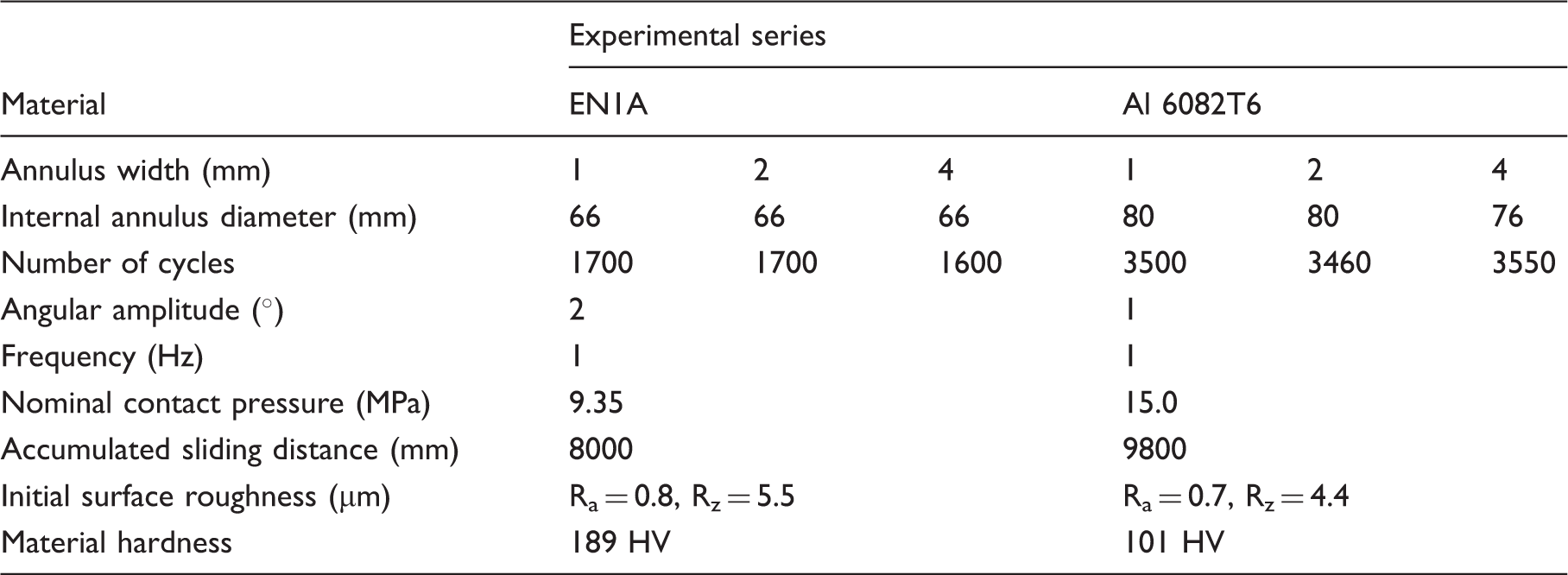
Experimental parameters for both experimental series. Note that the cycle numbers were varied to compensate for changes in median sample radius, keeping the accumulated slid distance constant in each experimental series.
In addition to the total mass loss, the steady-state wear rate was determined using the axial position of the bottom sample element, which gradually changed during the test, due to material removal from the sample elements. The axial position data were low-pass filtered to remove measurement noise and the linear portion of the data identified. The linear rate of change of axial displacement was multiplied with the nominal contact area and the density of the material to give the steady-state wear rate.
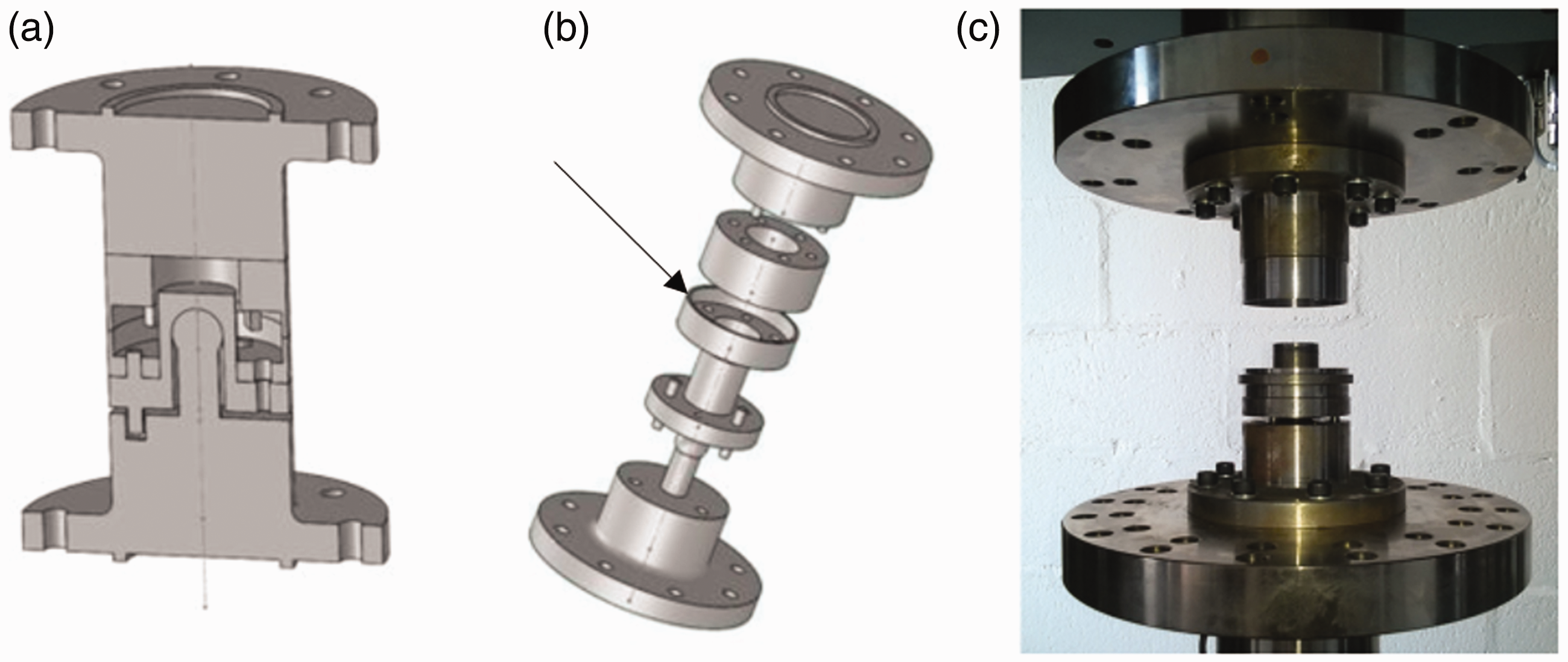
Specially designed sample grips were used to minimize the effects of angular misalignment of the samples on the distribution of contact pressure. In the steel test series, a self-aligning fixture with a spherical bearing on the contact plane was used, originally developed for the research project of Clark
17
; this fixture transmits torque via loading pins and is shown in Figure 1. As the normal load is applied, there is no resistance to the alignment of the fixture apart from the minimal friction between the lubricated and polished surfaces of the ball and the socket, ensuring an approximately uniform contact pressure by design. However, it should be noted that there is a small degree of inherent non-uniformity due to elastic deformation of the samples under load.
18
During the experimental series, it was noted that normal load excursions of up to 50% of the set value were occurring, mainly during reversal of the torsion direction. A stiff spring was inserted into the load path in an attempt to mitigate this. With the addition of the spring, the normal force oscillations remained within ±10% of set value.
In the aluminium series, a similar fixture using a spherical bearing was used; in this case, a bellows coupling was employed to transmit torque (see Figure 2(a)). The fixture was so designed that the bellows also act as the axial spring used in the previous fixture; the bellows need to be compressed by approx. 1 mm before the full load-bearing capacity of the fixture is obtained. Each sample element was gripped using a segmented collet, see Figure 2(b), allowing a simplified cylindrical sample design. The aluminium samples were designed to be significantly lighter than the steel samples, allowing the use of a more sensitive weighing scale, and hence giving improved resolution of mass loss.
Experimental device used in the second cycle of experiments. (a) The general layout (samples not fitted) and (b) the ring sample with showing part of the segmented collet.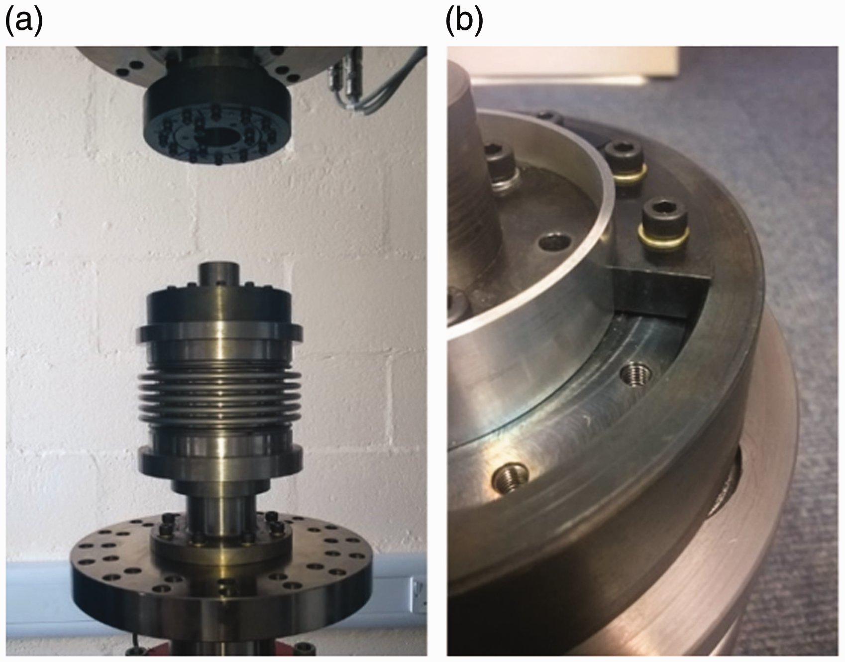
Results and discussion
Steel experimental series
Figure 3 shows how the total mass lost is distributed between the top and bottom sample elements in this series. The split is mostly even, as is expected in light of the geometrical symmetry, but in 4 mm annuli there is a tendency for more mass to be lost from the top element.
Distribution of mass lost between the top and bottom sample elements for the first cycle of experiments. Line of symmetry represents perfectly even split of total mass lost. Enlarged markers indicate two tests with identical results.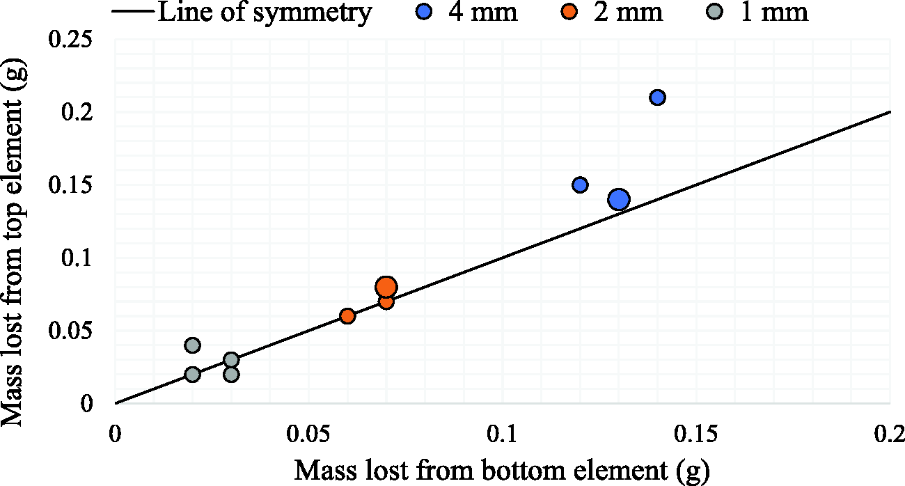
When the lost mass is plotted against the amount of work expended in wear, the points fit well to a straight line (Figure 4). Linear regression analysis gives an R2 value of 0.89 when all the data points are included. If the largest outlier is excluded (marked with a red circle) R2 raises to 0.99. Linear increase of wear volume with accumulated energy for identical contacts is frequently reported in the literature (see Fouvry and Merhej,
9
Hintikka et al.,
15
Hintikka et al.
18
and Heredia and Fouvry and Pearson and Shipway
20
). However, in this case, the linearity exists between contacts of different sizes.
Lost mass as a function of wear work and annulus width in the steel series. A red circle marks an outlier. Enlarged markers indicate two tests with identical results.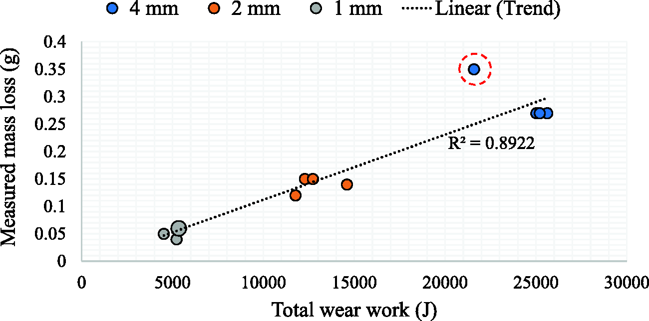
The principal purpose of this study was to establish whether increase in the width of the annulus increases wear debris entrapment (other variables being the same) or not. Increased entrapment should manifest itself through a decrease in wear. However, contacts with larger contact areas are expected to lose more material in total. To account for this, the total mass loss and the steady-state wear rate were normalized with respect to nominal contact area. Normalized total mass loss for the steel experimental series is shown in Figure 5. By excluding the largest and the smallest value (marked with red circles; both of these tests were conducted before the addition of the spring), the values fall into a range of 0.24–0.35 mg/mm2. No clear trend in wear versus annulus width is observed.
Total mass losses per unit contact area as a function of annulus width for the steel experimental series. The largest and smallest values are marked with red circles.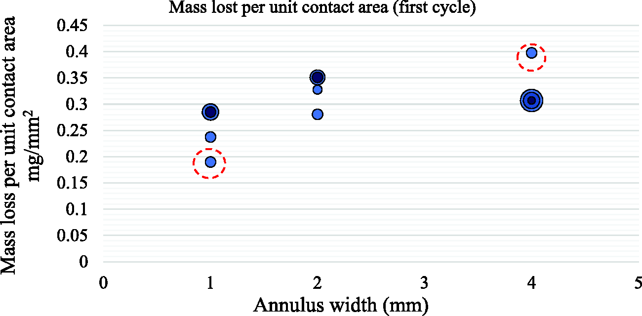
Steady-state wear rate normalized with respect to contact area is shown in Figure 6. There is significant scatter between tests and no specific trend is observed. As with the total mass loss, the steady-state wear rate is not decreased by increasing the width of the annulus.
Steady-state wear rate per unit contact area as a function of annulus width for the steel experimental series.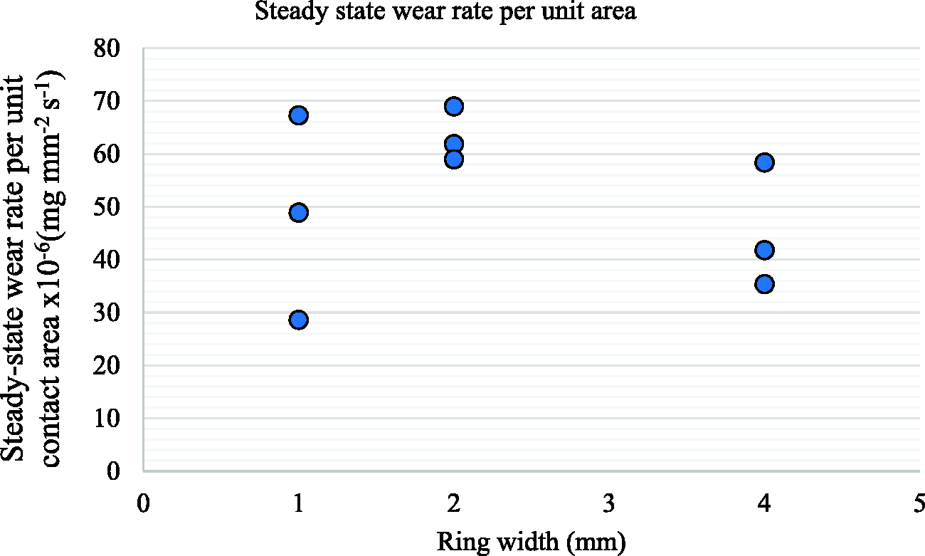
The results obtained with steel samples do not support the hypothesis chain of wider annulus → improved wear debris entrapment → less wear. The notion improved wear debris entrapment → less wear is widely accepted and has been observed in different contact geometries and for different materials.4,5,7,8,11 It appears unlikely that annular contacts in this study are an exception to this principle. Therefore, it appears likely that wider annuli do not increase debris entrapment. A simplified model of debris flow was developed to explain this, demonstrating that annulus width may not influence entrapment under certain conditions.
Debris bed mass flow analysis and entrapment
Entrapment of debris is defined as containment of the debris between wearing surfaces.20,21 This is commonly assessed qualitatively; however, to compare the extent of debris entrapment, it is desirable to have a quantitative measure. For this purpose, we adopt the average time needed for a debris particle to escape from the contact after its release into the debris bed. Consider the debris mass flow in a radial cross-section of the annular contact, as shown in Figure 7. As the annulus width is small compared to the radius, the contact can be approximated by a pair of infinitely long straight walls, of width 2L, separated by a debris bed layer of thickness H. As it has been demonstrated that larger values of H decrease wear10,23 and since wear observed in steel annuli scales simply with contact area, we assume as a first approximation that H is independent of L. In addition, H is most likely to be influenced by contact pressure, which has also been kept constant. We also assume that mass is lost from the surface uniformly, with mass loss rate per unit area M. The contact is symmetrical with respect to a central vertical plane (distance L away from either edge) and it is assumed that there is no net mass transfer across this symmetry plane.
Cross-section through an idealized annular contact. The slip direction is in/out of the page.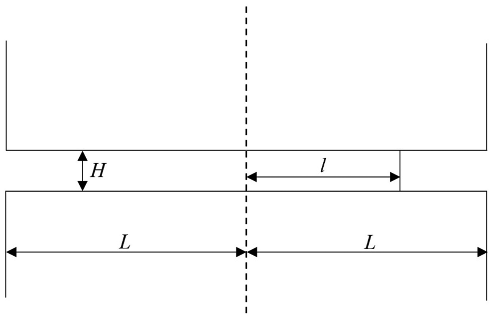
In steady-state, the mass flux of debris in the radial direction, 
The debris flows through the gap between the surfaces of the first bodies. Using equation (1) and denoting the bulk density of the debris ρ, the radial velocity of the flow, vr, is

It is assumed that each particle removed from the first bodies immediately obtains the radial velocity of the flow at that position. A particle travelling with the speed vr travels a distance dl in time dt. Using equation (2) we obtain

Hence

The quantity Hρ/2M defines a characteristic time t* which we take to be a constant. Solving equation (4) gives


Equation (7) identifies the characteristic time t* as the average time debris particles spend in the contact. This time is independent of the width of the annulus. The finding is consistent with the results observed in the steel experimental series: wear rate per unit area is the same, since entrapment levels are approximately the same as entrapment is not directly dependent on contact width and other parameters were held constant. Equation (7) contains no material property except debris density, and no dependence on the wear contact conditions such as pressure, displacement or sliding velocity. However, it is based on the assumption of an unobstructed flow of debris through a channel of uniform rectangular cross-section. To test whether this is a realistic assumption for other contacts, the aluminium experimental series was carried out using different pressure, displacement and material, but varying only the annulus width within the series. This directly tested whether the wear rate is independent of annulus width.
Aluminium experimental series
In the aluminium experimental series, the mass loss was evenly split between the top and bottom sample elements, as was the case for steel samples (Figure 8). However, the total mass loss is smallest in 4 mm wide rings, as opposed to being the largest, as was the case in steel rings. This may appear paradoxical, but it should be borne in mind that total mass loss represents the effect of the entire process of wear: the initiation of surface damage, galling of surfaces, generation of the wear debris bed and finally steady-state wear. When using aluminium rings, the number of cycles needed to reach steady-state wear increases roughly in proportion with the size of the contact area, meaning that while a steady-state was reached in all cases, this required more cycles in wider rings, eventually causing less wear to be accumulated over-all. This explanation is further supported by the fact that total mass loss in 2 mm aluminium rings is less than twice that in 1 mm rings, indicating that the run-in period of the contact was longer. In the steel rings, the steady-state was reached much more quickly, making the steady-state part of wear mask the transient wear phenomena. The reasons for the difference are not fully clear; the authors speculate that the most likely explanation is that aluminium, possessing higher ductility than steel, required more energy to be expended (and hence more cycles to be accumulated) in order to initiate wear and establish a tribologically transformed structure.
Distribution of mass lost between the top and bottom sample elements for the aluminium experimental series. Line of symmetry represents perfectly even split of total mass lost.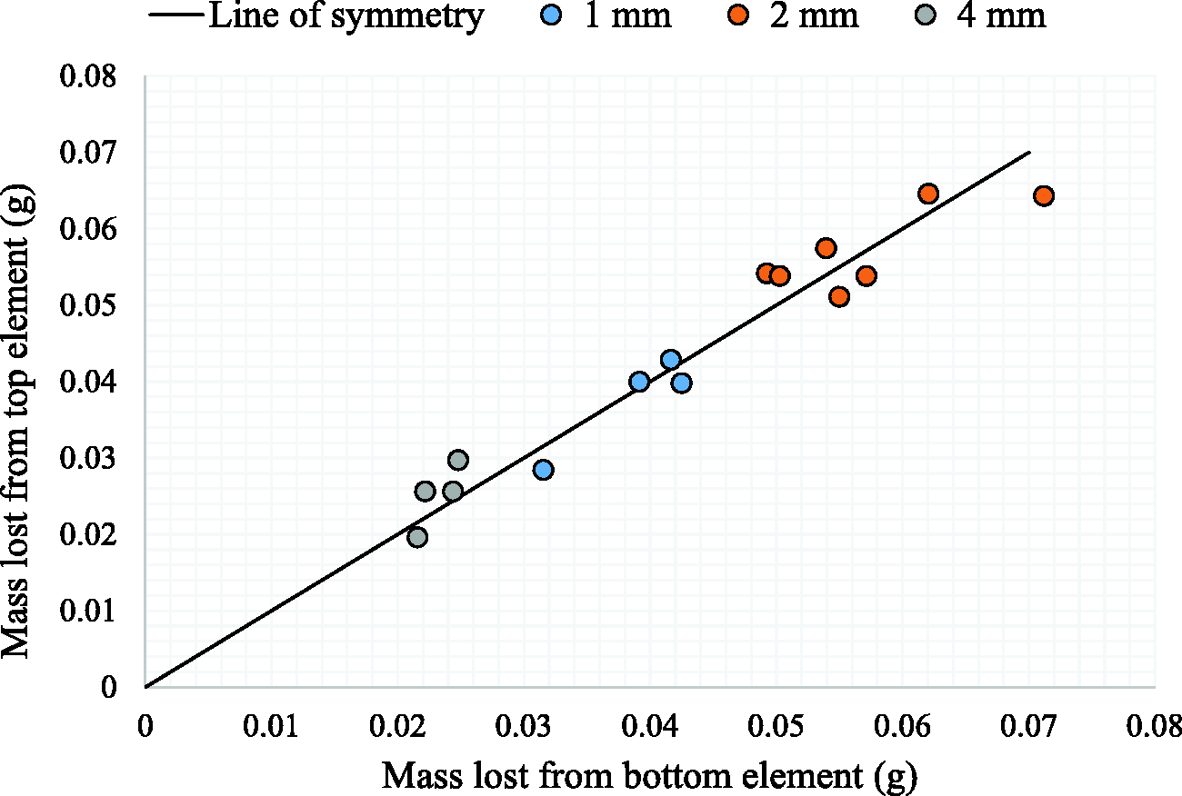
When the total mass loss is plotted against accumulated wear work, no particular trend is observed between annuli of different widths (Figure 9).
Total mass loss as a function of accumulated wear work in aluminium experimental series.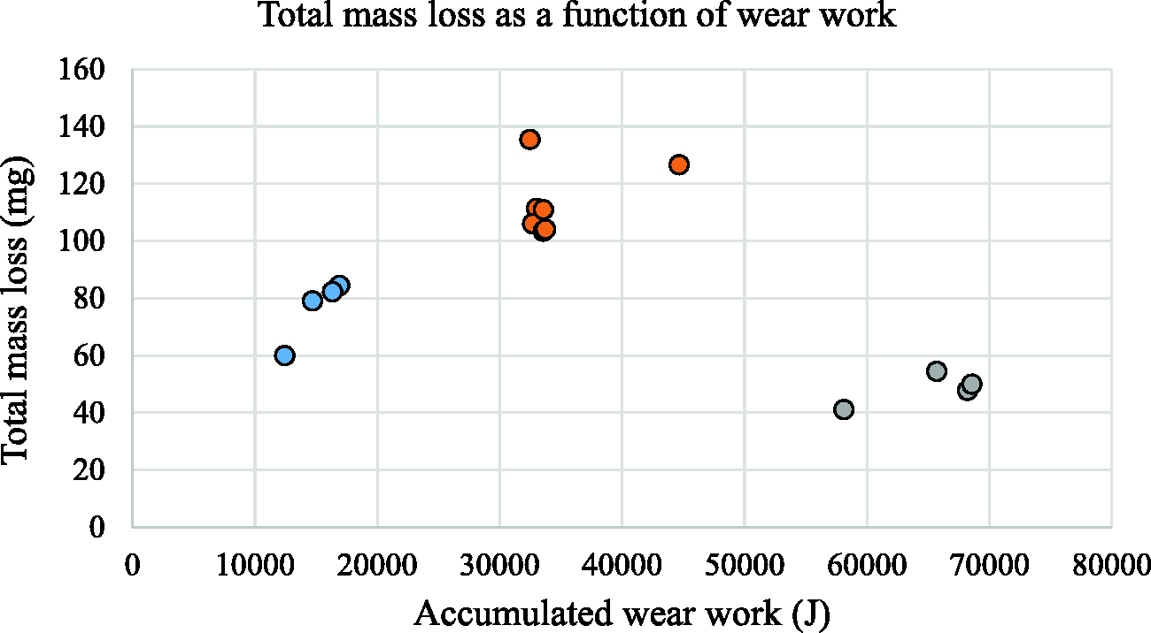
When normalizing the total mass loss with respect to contact area a clear negative trend is observed, with the normalized mass loss decreasing with annulus width (Figure 10).
Total mass loss per unit of contact area as a function of annulus width in the aluminium experimental series.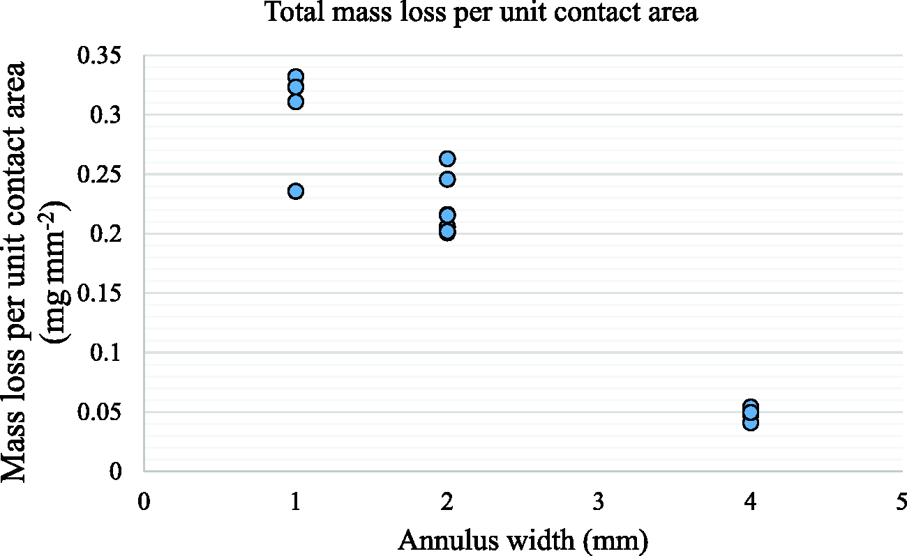
The same trend is observed when the steady-state wear rate is normalized with respect to the contact area, as seen in Figure 11.
Steady-state wear rate per unit area as a function of annular width in the aluminium experimental series.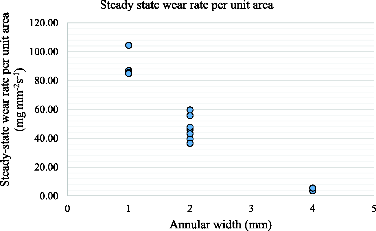
The aluminium experimental series shows that wear (as measured by total mass loss or steady-state wear rate) decreases with annulus width, which is consistent with an increase in wear debris entrapment. This contrasts with the steel experimental series, where the wear was almost independent of annulus width.
In both experimental series powdery wear debris was produced. A scanning electron microscope (Zeiss, EVO LS 15, Germany) was used to observe and study the wear debris particles (Figure 12). When steel was used, the debris accumulated inside the bottom sample and was easily collected for further study. When aluminium was used, this was not practical, so an adhesive tab was applied directly to the contact surface after wear to collect the wear debris. The steel debris particles are mostly flake-shaped, ranging in size from 2 to 300 µm, with 10–20 µm being typical. The flake thickness is estimated at 5–10% of its diameter. There were no visually discernible differences between the particles obtained from contacts of different widths. The aluminium debris was also in the form of flakes, in a similar size range of 2–200 µm. Debris collected from the 1 mm aluminium rings consisted primarily of relatively large flakes (over 50 µm across and approximately 5 µm in thickness), with wider rings tending to produce smaller debris particles (although some larger ones were still found).
Wear debris particles. (a) 1 mm wide steel, (b) 2 mm wide steel, (c) 4 mm wide steel, (d) 1 mm wide aluminium and (e) 4 mm wide aluminium.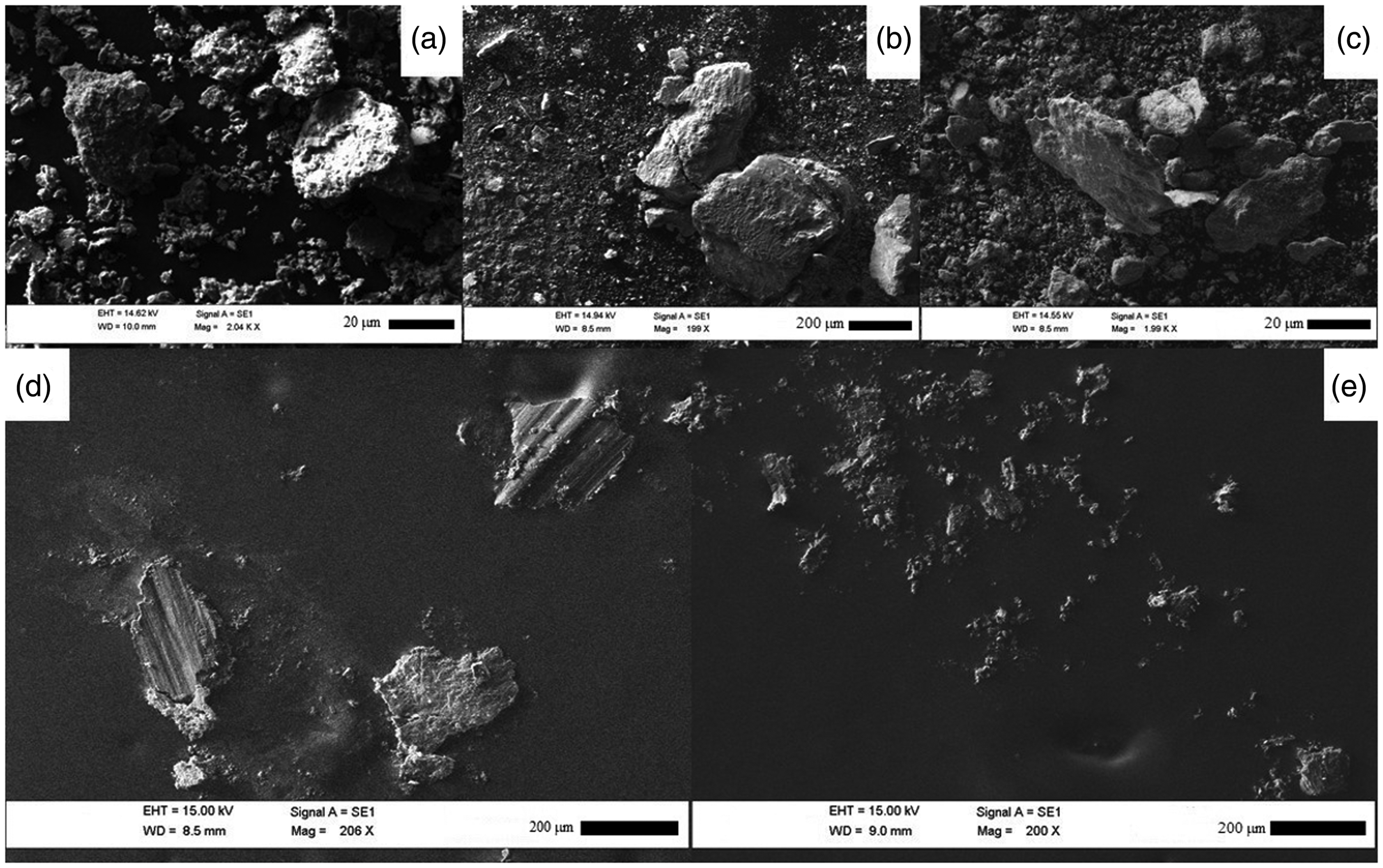
The difference in wear behaviour observed suggests that debris entrapment is influenced by factors other than the width of the annulus. However, the annulus width was the only geometrical parameter varied in the experimental design of each series. This indicates that a self-establishing length scale may affect the entrapment process. In this case, varying the width of the annulus is not sufficient to deconvolute the factors influencing debris entrapment.
Some observations concerning what this length scale might be can still be made. One possibility is that the worn surface roughness could differ between the two experimental series. To test this, an optical profilometer (InfiniteFocus, Alicona, Austria) was used to examine the worn surface profiles. Profiles were taken in the radial direction with start and end points approximately 100 µm away from the inner and outer edge of the annulus. It was determined that the worn aluminium surfaces were considerably rougher than the worn steel surfaces. This is illustrated in Figure 13, which shows a comparison between representative primary radial surface profiles in 2 mm wide annuli. For brevity, only two profiles are shown for each material, but they illustrate a general trend observed on several profiles in all three contact geometries.
Four randomly chosen radial surface profiles from 2 mm wide annuli (two from steel and two from aluminium samples).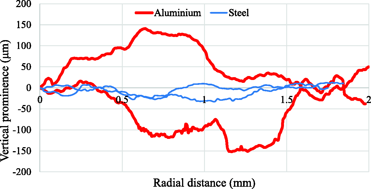
A more detailed roughness analysis shows that the worn surface profiles are consistently rougher in the aluminium annuli and also that the profile roughness increases with annulus width (see Figure 14).
The relationship of Ra primary profile roughness and annulus width in steel and aluminium experimental series.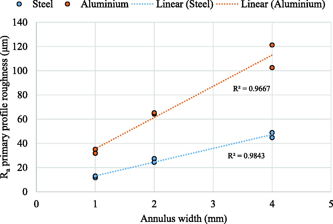
The derivation of equation (7) assumes a ‘steady’ flow of debris through the debris bed. It is possible that the rougher worn surfaces occurring in the aluminium annuli disturb the flow of debris. In the steel annuli, no systematic dependence of wear was observed and the worn surface was relatively smooth with the largest particles observed (Figure 12) having diameter several times larger than the vertical prominence of the worn profiles meaning that they essentially ‘prop’ the contacting surface apart, allowing smaller debris to pass more easily. The argument developed in the ‘Debris bed mass flow analysis and entrapment’ section could then be expected to apply at least to some degree. In the aluminium annuli, however, the surface wears to a much rougher profile, invalidating the assumptions of the simplistic mass flow explanation that led to equation (7). Comparing the roughness profiles in Figure 14 with the debris sizes noted from Figure 12, it is evident that the scale of roughness established in the aluminium specimens is capable of locally accommodating even the largest debris particles with room to spare. Debris particles are thus forced to ‘pool’ in large voids or are blocked by large asperities. The notion that surface roughness can affect debris entrapment has been proposed in prior studies,24,25 with a threshold effect observed, where roughness effects only occur when the roughness parameter of the surface is large enough compared to the size of the wear particles. Taking this into account, the differences observed between the two experimental series can be explained in terms of material propensity to wear into a particular morphology under the experimental condition used.
Conclusions
Wear of annular contacts made of EN1A steel and 6082T6 aluminium alloy was studied to test whether wider annuli entrap wear debris to a greater degree, causing the amount of wear to decrease. The experimental results in steel rings showed no particular trend in wear as the annulus width was changed. To explain the independence of wear on annulus width, a simple model of the radial debris flow velocity profile was developed. In this model, the average time from particle creation to ejection was found to be independent of annulus width. Taking this time as a measure of debris entrapment explains the experimental observation in steel rings. A second experimental series using aluminium alloy rings and a different set of wear conditions was performed to test whether the model assumptions are more generally applicable. The normalized wear in the second series showed a clear trend of decreasing with the ring width. Based on measurements of the worn surface profiles we conclude that the most likely explanation for the different wear behaviours observed is that the aluminium rings wear into a much rougher surface profile, which influences the flow of debris to a greater extent, than the relatively smooth worn profile of steel samples. This would cause the debris entrapment to increase significantly with ring width in the case of aluminium alloy annuli, but not so in the case of steel annuli. It should be noted that the worn-in surface roughness is not a controllable experimental variable, but rather a self-determined length scale likely to affect wear. A predictive understanding of the factors affecting the worn-in surface roughness is desirable, but not currently available.
The present study highlights the significance of both debris flow in wear and the worn surface roughness affecting debris entrapment. To conclusively determine the influence of these factors, the debris flow would need to be observed during wear in-situ, which was not done in this study, as the only mature experimental approach for doing so requires the use of transparent wear bodies. However, an X-ray wear imaging approach is currently being developed to enable the visualization of debris beds in metal–metal contacts. This will be reported in a future publication.
Footnotes
Declaration of Conflicting Interests
The author(s) declared no potential conflicts of interest with respect to the research, authorship, and/or publication of this article.
Funding
The author(s) disclosed receipt of the following financial support for the research, authorship, and/or publication of this article: The authors acknowledge funding obtained under project ‘Extended wear law' supported under contract number 4800000925 by Rolls Royce Plc.