
Abstract
Fuel efficiency is one of the main concerns in the optimisation of modern racing transmissions. The dry sump transmissions are the preferred choice for high performance racing applications. While it provides adequate lubricant for gear contacts, it minimises the system churning losses, and therefore enhances the system efficiency. An important aspect is assessing its thermal performance in removing the generated frictional heat. The generated heat in the highly loaded high shear contacts of racing transmissions should be dissipated through use of directed impinging oil jets and in an air–oil mist environment. The paper presents an integrated tribological and three-dimensional computational fluid dynamics analysis for a spur gear pair, incorporated into an overall finite element model to evaluate the quantity of generated heat and its removal rate from the rotating gear surfaces. Furthermore, the temperature distribution in the circumferential direction is predicted and used to evaluate transient temperature distribution over representative race laps. Such an approach has not hitherto been reported in literature.
Keywords
Introduction
Transmission efficiency and durability are key areas of research in high performance systems. Power losses in such systems are categorised as load-dependent and load-independent losses. The load-dependent losses are the result of generated contact friction of meshing gear pairs and their supporting bearings. Various numerical and experimental studies have investigated these frictional losses for different gearing systems, also taking into account the effect of gear teeth geometry, noise and vibration, and fatigue performance.1–5 The transmission of high performance race vehicles comprises a series of spur and bevel gear pairs. The gear teeth pairs operate under highly loaded high-shear contacts. Under such conditions, a thin film of lubricant is formed, which is subjected to non-Newtonian shear with inlet shear heating and often starved inlets as described by Paouris et al. 6 For spur gear pairs, Li and Kahraman1,7 introduced a numerical model to predict the frictional losses. Their mixed-elastohydrodynamic lubrication model was used to estimate both instantaneous and total power loss during a gear meshing cycle. In a transmission system, there exists multi-pair of gears, some with several simultaneous teeth pair contacts. Therefore, an analytic predictive method is preferred due to its computational efficiency. Fatourehchi et al. 2 introduced an analytical method with improved computation times, based on the analytical–experimental lubricant film behaviour reported by Evans and Johnson 8 in order to predict gear contact power loss in high performance transmission systems. The same method was used in Fatourehchi et al. 9 to perform a parametric study for the effect of tooth modification on planetary spur gear system efficiency. In both cases,2,9 tooth contact analysis was used to accurately represent the contact geometry, kinematics and load share per meshing teeth pairs in the analysis.
Load-independent power losses are mainly due to churning and windage losses. The drag of lubricant between the rotating gear teeth is the main cause of these losses. Consequently, these losses are mainly influenced by the method of lubrication. Splash lubrication system is mostly utilised in automotive transmission systems for cooling and lubricating purposes. In such a system, the gears are partially immersed into an oil sump, and splash the oil while rotating. Therefore, churning losses are the main source of load-independent losses in these systems.
Several studies have been carried out to determine the churning losses in gearing systems.10–13 Changenet and Velex 10 proposed a series of equations to estimate churning losses of a gear for a wide range of speeds, different geometries, lubricants and immersion depths. The equations were experimentally validated. Later, Changenet et al. 11 extended these formulations to take into account the centrifugal effects. They showed that thermal transience, centrifugal effects and aeration are important factors in predicting churning losses, and that lubricant viscosity or Reynolds number are not the only influential factors. Seetharaman and Kahraman 12 introduced a numerical model to determine the churning losses of gear pairs. The model was validated against experiments. 13
To overcome or reduce such churning losses, dry sump lubrication system is introduced. In dry sump lubrication system, the lubricant is fed into the gear meshing conjunctions through directed impinging oil jets, which also contribute to cooling. The impinging jets contribute to cooling by dissipating the generated heat in the contact. A critical aspect in dry sump systems is to ensure the penetration of adequate lubricating and cooling oil into the meshing teeth contacts. According to Akin, 14 the controlling factor in preventing the potential gear failure modes (e.g. scoring and scuffing) is the gear bulk temperature. This necessitates the proper cooling of the gear teeth in order to prevent the excessive surface temperature and consequently failure of the gear teeth.
An analytical model was introduced by DeWinter and Blok 15 to obtain the heat dissipation rate through an impinging jet from the surface of the gears. The model assumed the formation of the laminar film layer on the gear flank, which overestimates the film thickness and consequently the heat dissipation rate.
One of the first numerical analyses of temperature distribution of spur gears lubricated through impinging oil jet was by Patir and Cheng. 16 They developed a finite element (FE) model, which was based on a method proposed by Wang, 17 determines the equilibrium temperature distribution for a spur gear. They used estimated analytical equations for heat transfer coefficients on different parts of their model. Recently, Fatourehchi et al. 18 developed a transient multiphase computational fluid dynamics (CFD) model to more accurately determine the heat transfer coefficients for different parts of a loaded gear pair for a wide range of operational conditions. They introduced regressed equations as an aid for the calculation of heat transfer coefficient on a gear surfaces lubricated and cooled under dry sump lubrication system.
Long et al. 19 developed an analytical–numerical model to obtain the gear teeth temperature for various applied loads. A thermal equilibrium was assumed for all parts of a gear. Wang and Cheng 20 also used the same assumption.
The review of literature shows that jet-lubricated gear thermal analysis lacks requisite accuracy. In particular, previously used FE analyses are based upon steady-state conditions. Steady-state thermal analyses of gear systems ignore periodic heat generation in meshing gears. It is important to note that heat is generated at a faster rate than its dissipation through convection to the ambient and conduction through the gear body (e.g. a gear undergoes meshing contact for approximately 3% of its rotational period). Therefore, in order to predict the thermal equilibrium a transient analysis is required. This is to determine the generation and dissipation heat (in Joules) and not the heat transfer rate (in Watts) for every rotation of a gear.
This paper presents an integrated model for a gear pair, where the transient generated heat due to mixed thermo-elastohydrodynamic contact friction is dissipated through convection cooling from the gear surfaces due to an impinging oil jet in an air–oil mist environment of a dry sump transmission. Part of the generated heat is also conducted away through the solid surfaces into the body of the gear pair. The model predicts the transient temperature distribution for a race vehicle under real race conditions, leading to steady-state temperature fluctuation. Such an integrated approach has not hitherto been reported in literature.
Methodology
The developed method combines various numerical analyses. An FE-based tooth contact analysis (TCA)21,22 is used to determine the instantaneous radii of curvature of meshing teeth pairs at any point during a meshing cycle, as well as contact surface velocities and the orthogonal meshing contact loads. These parameters are input to the mixed-elastohydrodynamic analysis to determine the contribution of viscous and boundary friction for a gear pair meshing cycle. Consequently, the generated heat and the contact temperature rise is evaluated. A transient multiphase CFD model is developed to determine the heat removal from the gear surfaces through application of impinging jets in the air–oil mist environment of transmission housing. Results of the parametric CFD analysis are used to determine the heat transfer coefficients for different surfaces of the gear. The tribological heat generation model, as well as the CFD analysis of heat removal form parts of an overarching thermal FE model in evaluating the temperature of the solid bodies under transient conditions.
Tooth contact analysis
Different microgeometrical tooth profile modifications are applied to the gearing systems of high performance transmissions for both reasons of transmission efficiency and structural durability. These modifications have notable influences upon the generated heat (i.e. power loss) in meshing contacts.
2
Therefore, the use of accurate tooth contact analysis to capture the effects of tooth profile modifications is essential in the thermal analysis of the gearing systems. The TCA model in this study is based on the FE method introduced by Vijayakar
22
and Xu and Kahraman.
23
The instantaneous contact geometry, lubricant entrainment speed (average speed of the meshing surfaces) and the relative sliding surface speed of the meshing teeth, as well as the load share per teeth pair contact are obtained through the developed TCA model.
24
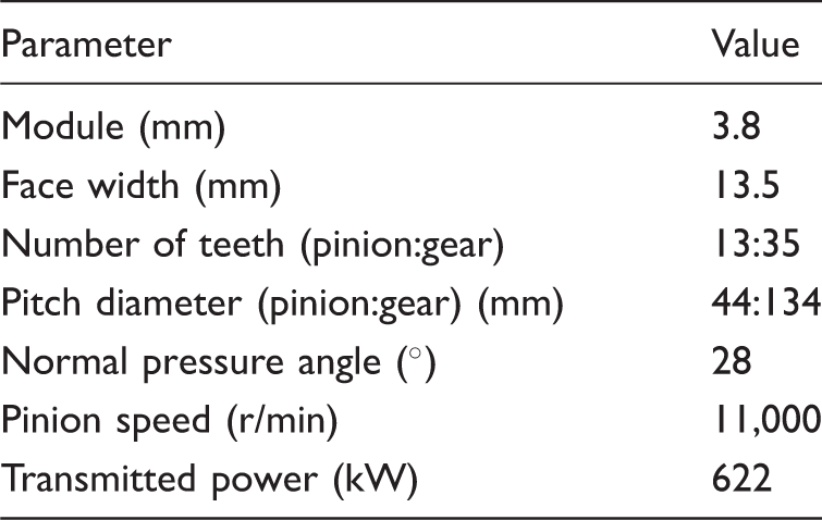
The developed TCA model neglects the effect of tooth bending for the determination of contact kinematics (rolling and sliding velocities) and radii of curvature. However, the effect of tooth bending is taken into account in the determination of the normal contact load in a meshing cycle as it affects the load share ratio between teeth pairs in simultaneous mesh. Figure 1 shows the TCA model results, based on the listed geometrical and operational properties of the crowned spur gear in Table 1.
TCA of a gear pair model results for a meshing cycle: (a) radii of curvature; (b) lubricant entrainment speed; (c) sliding surface speed; (d) normal applied load. Gear geometrical and operational properties.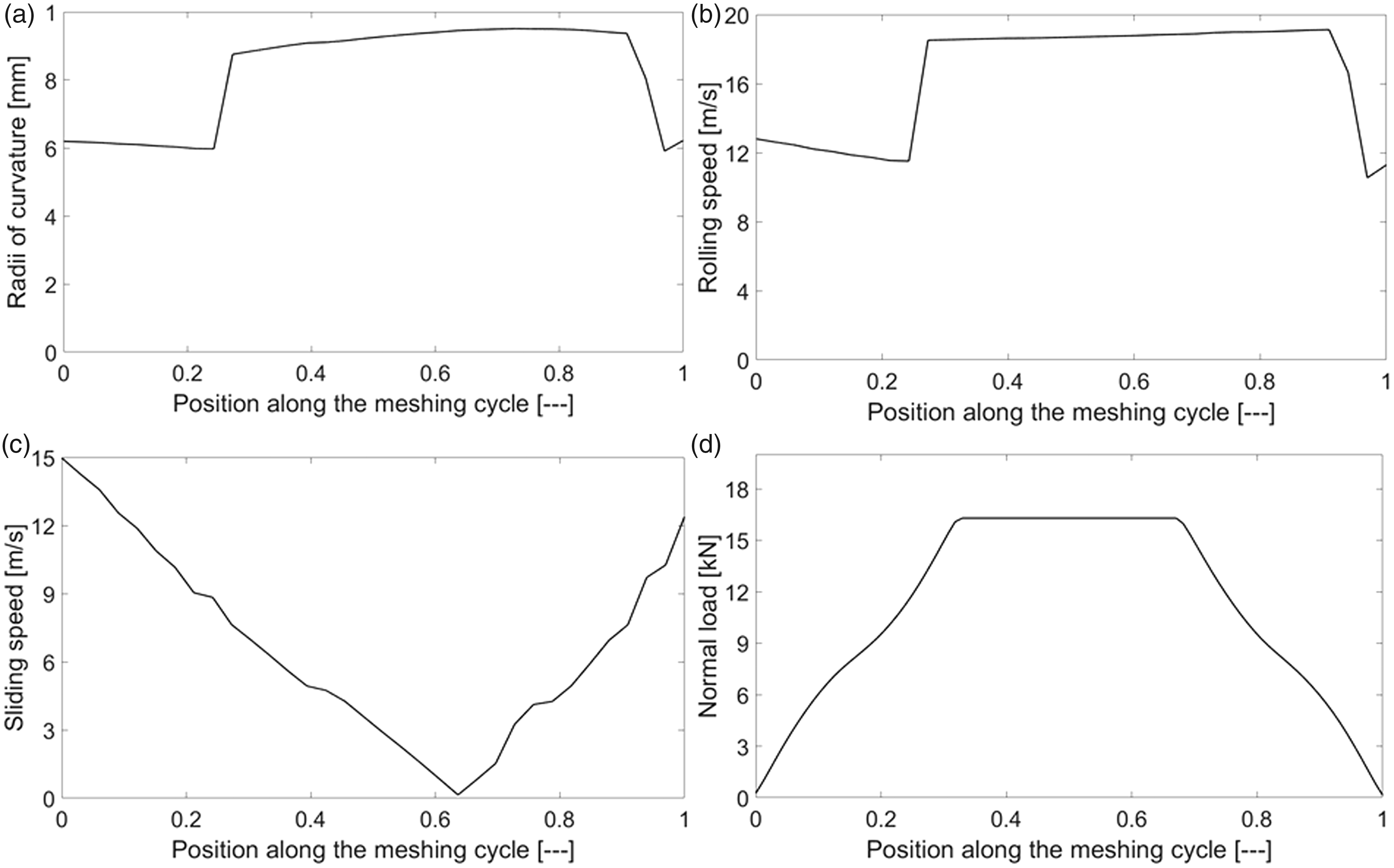
As shown in Figure 1(a) and (b), there are sudden jumps before and after the single teeth pair contacts (i.e. around the meshing positions 0.3 and 0.9). These jumps are as the result of applied tip relief on the gear teeth. 25
The elastohydrodynamic contact model
The proposed model is time-efficient, simulating a meshing cycle of spur gear pair in a couple of seconds. This is essential in performing iterative FE analysis, where it is required to update the quantity of the generated contact heat due to the variation in kinematics of the meshing teeth pairs.
Loaded gear teeth of high performance transmission systems operate under high contact loads, in excess of 20 kN. The resulting high contact pressures promote the formation of thin elatohydrodynamic films of the order of the root mean square (RMS) average surface roughness of the counter face surfaces.
26
This promotes mixed regime of lubrication, with friction generated according to two additive contributions; viscous shear of a thin lubricant film, and adhesive boundary friction as a result of direct interaction of asperities on the contiguous meshing surfaces. Therefore, the instantaneous power loss during the meshing cycle is obtained as

Boundary friction
Here, the method developed by Greenwood and Tripp27 is used to determine the boundary friction. The method assumes a Gaussian distribution of asperity peaks. For mixed regime of lubrication, the Stribeck oil film parameter resides in the region: 
Gear surface roughness parameters.
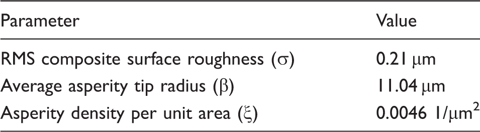
RMS: root mean square.
The interactions between the counter face opposing asperities generates boundary friction, which should be considered in the case of mixed or boundary regimes of lubrication. A thin adsorbed film resides at the summit of the asperities or is entrapped in their inter-spatial valleys. This film is subjected to non-Newtonian shear; thus, boundary friction fb becomes
26


The asperity contact area is
27

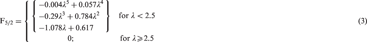
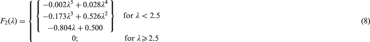
The statistical function F2(λ) is obtained as
28
Viscous friction
The coefficient of viscous friction generated due to shear of a lubricant was obtained by Evans and Johnson
8
as

This equation covers both Newtonian and non-Newtonian tractive regimes.
8
The instantaneous lubricant film thickness under the operating conditions is calculated using the lubricant film thickness formula introduced by Chittenden et al.
29


The variation of viscosity with pressure is based on the Roelands’ equation,
30
which was also used in the numerical model of Chittenden et al.,
29
thus embedded in equation (10). The effect of pressure on the lubricant density is taken into account, based on Dowson and Higginson
31
as

It should be noted that the film thickness equation (equation (10)) is derived based on the isothermal conditions. Neglecting thermal effects in the determination of film thickness is reasonable since the generated heat in the contact has a small effect on the film thickness. 32
The generated viscous friction, using equation (9), becomes

It is assumed that the total generated power loss in the contact would convert to heat. It is also assumed that the convective heat transfer through a thin elastohydrodynamic film is negligible. 28 Therefore, the generated contact heat is almost entirely conducted through the contacting teeth surfaces. This results in an increase in the temperature of mating surfaces. A part of the generated heat is then convected away by an impinging oil jet directed towards the contacting teeth, just after the mesh point, as well as by the air–oil mist environment of the dry sump transmission casing. These maintain the transmission thermal balance. The flank surface temperature rise is considered as the heat source in the CFD model. In order to consider this boundary condition, the tribological model should be integrated into the CFD analysis.
The contact of a pair of cylindrical spur gear teeth yields a finite line rectangular band of width 2b.
28
For convenience, friction per unit length is obtained as

Therefore, the heat generated due to the power loss per unit length of contact becomes TUs. Assuming that the generated heat flows equally to both the contacting surfaces, Crook
33
showed that the average surface temperature rise would be (which is the boundary condition for the CFD model)

The computational fluid dynamics model
A standard k-ɛ turbulence model is developed to analyse an impinging lubricant flow on a rotating gear. The model is similar to that developed through CFD by Fatourehchi et al., 18 which was qualitatively validated against the findings of DeWinter and Blok. 15 The governing equations for conservation of mass and momenta for each phase in a 3D Newtonian and incompressible turbulent flow are according to the approach proposed by Hou and Zou 34 as follows.
The continuity of flow condition

Conservation of mass and momenta

Turbulent kinetic energy

Dissipation rate of k


The constants in the above equations are obtained from Launder and Spalding
35
as
The energy equation is
37

The interface between the immiscible liquid lubricant and the liberated vapour phase is monitored using the volume of fluid (VOF) method.
38
A volume fraction function 
The surface tension model is the continuum surface force (CSF) model introduced by Brackbill et al.
39
The interfacial tension is calculated using this model and added to the source term in the momentum equation (16). According to the VOF function, the interface unit normal (
Hence, the force source 
To solve the system of equations in the CFD model, the commercial CFD package Fluent 16.2 (ANSYS Inc.), based on the finite volume method is used. 40 A 3D CFD model is developed to determine the effect of different parameters in a combined oil jet and air–oil mist lubrication system. The CFD analysis is carried out using a pressure-based VOF model. The coupled algorithm is selected to treat the velocity-pressure coupling. The flow is computed by a standard k–ɛ turbulent flow model.
Schematic representation of the developed CFD model is represented in Figure 2. Boundary conditions of different parts of the gear body are shown in the figure. To enhance the heat dissipation from a gear pair, the oil jet impinges toward the exit of the meshing teeth contact. Hence, the effect of the impinging oil jet can be assessed on any gear body in mesh, assuming that it has received half the generated heat in the gear contact. It is assumed that the effect of changes in flow pattern around the contact zone induced by the mating gear pairs is negligible in the determination of gear surface heat transfer coefficient. Therefore, the CFD simulation is performed on a single gear.
Schematic representation of the CFD model.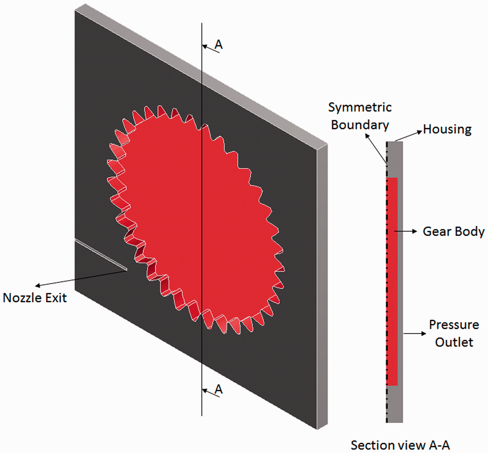
According to Figure 2, a large box is considered for the rotating gear. This is to minimise the impact of the computational boundary upon the results. It is assumed that the gear flank temperature remains constant. The temperature is determined through the introduced tribology model. The impinging oil mass flow rate at the nozzle exit is 0.0168 kg/s at 100 ℃. The atmospheric pressure is assumed at the outlet boundary.
The integrated system model
An FE model is developed, which takes into account the effect of generated heat (determined using the tribological model) and the dissipated heat (estimated by the CFD model). This is to assess thermal performance of a gear pair. A gear is assumed to be formed from several tooth segments. All gear teeth experience the same heating and cooling conditions in the periodic gear revolution. Thus, the resulting temperature distribution is identical for all gear teeth. Therefore, the thermal analysis can be performed on a single tooth segment.19,20 Boundary conditions of the developed FE model of a single tooth segment are shown in Figure 3.
A tooth segment with the defined finite element model boundary conditions.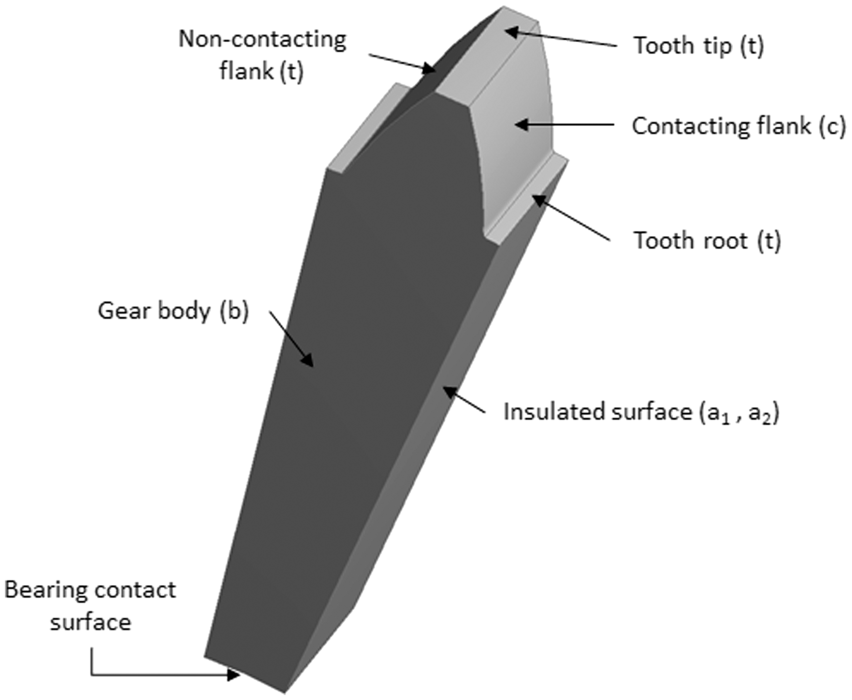
Thermal analysis and boundary conditions
A highly loaded high-speed gear pair, which operates in a dry sump lubrication system, is mainly cooled by a mixture of air and oil mist. 20 Therefore, the conducted heat through the supporting bearings is negligible.
In each revolution of the gear, the generated heat flux due to the contact power loss is applied to the meshing flank. The Fourier heat conduction equation is the governing equation to determine the temperature distribution

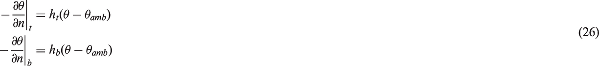
Considering circumferential symmetry, the intersections of teeth elements are considered as insulated, where the insulated heat condition is given as

Solution method
The above system of equations (in the overarching FE model) is solved utilising the commercial FE package, MSC Nastran 2014.1. 41 It is not practical to use commercial FE software in order to run simulations for a complete drive cycle owing to an inordinately long computation times. Therefore, a Matlab model is developed to interface with the FE model: (1) calculate the generated contact heat, using the tribological model, (2) determine the convective heat transfer coefficients, using the CFD model, and (3) update the gear temperature, as well as the conductive heat transfer to the contacting flank (Figure 3).
The integrated methodology incorporates a tribological heat generation model and CFD model of an impinging oil jet on a rotating gear into a transient FE model of a tooth segment. This is to determine the transient temperature distribution on different surfaces of the gear as well as convection heat flux from the gear surfaces.
Below the computational procedure of the integrated method is described:
Step 1: The instantaneous radii of curvature, the kinematics of the contacting meshing pairs and normal applied contact loads are determined for a complete meshing cycle, using TCA. These form the inputs to the tribological contact analysis, leading to the evaluation of contact power loss.
Step 2: The generated heat and the resultant average surface flash temperature rise in the contact for a meshing cycle is obtained through the mixed-elastohydrodynamics model.
Step 3: The temperature rise is an input to the developed 3D CFD model in order to calculate the heat transfer coefficients of the gear tooth surfaces and the gear body (Figure 3).
Step 4: The generated heat and the heat transfer coefficients of the gear tooth and body form the inputs to the FE model in order to obtain the transient temperature distribution.
Step 5: At the end of each gear revolution, the FE model is interfaced with the Matlab model to initialise the nodal temperatures and the conducted heat to the contacting flank for the analysis of the following revolution of the gear.
Step 6: Representative operating conditions of a typical race lap are considered. The process runs until the temperature at the start and the end of the race lap equilibrates (i.e. the temperature distribution reaches the steady-state condition).
Results and discussion
Lubricant properties.
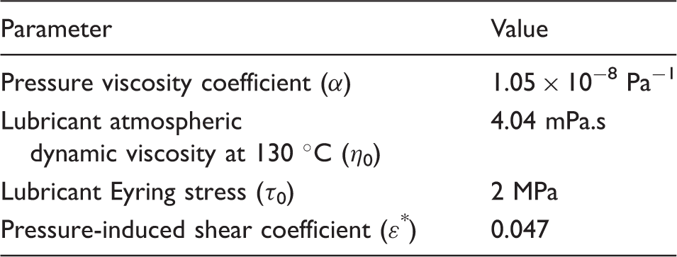
Figure 4 shows the variations of speed and gear shifting sequence, monitored in real time during a complete race lap.
Variation of speed and engaged gear number during a lap.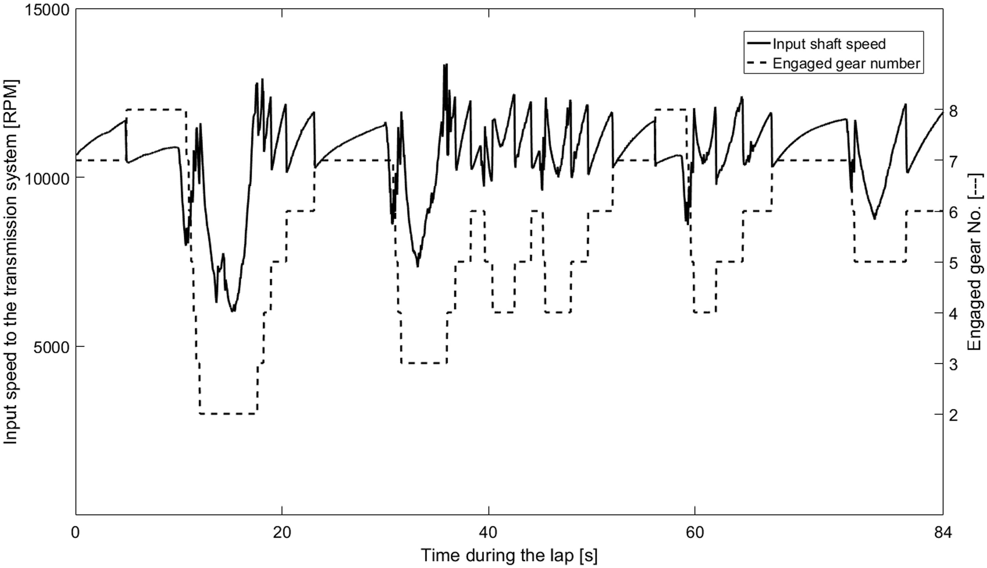
The 7th gear pair is the most engaged of all the gear pairs during the race (approximately 30% of the total lap time). Therefore, this gear pair is subjected to a greater frictional heating and runs at a higher temperature than the others. Therefore, the operational condition of the 7th gear is selected in this study to monitor the most critical temperature rise noted in practice on the gear surfaces.
With the 7th gear in contact, the variation in transmitted torque is merely 50 Nm. Therefore, an average torque of 540 Nm is considered. However, the variation in kinematics of meshing teeth pairs is included in the analysis for the determination of gear mesh tribological parameters. Figure 5 shows the variation of central lubricant film thickness in a meshing cycle for the mid-velocity condition.
Variation of lubricant film thickness along a meshing cycle.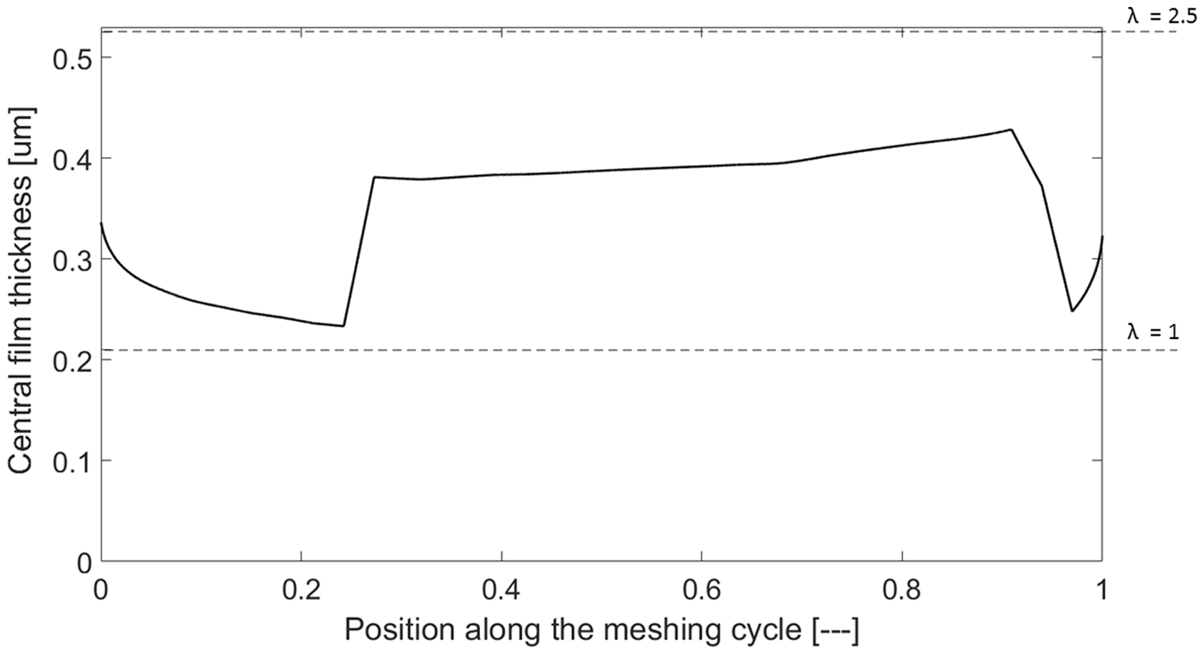
The predicted central film thickness varies between 0.2 and 0.45 µm. Considering the measured surface roughness of 0.21 µm, the Stribeck oil film parameter λ resides between unity and 2.5. Therefore, mixed regime of lubrication is expected throughout the meshing cycle. Consequently, the generated heat in the contact is as the result of a combination of both viscous and boundary friction contributions. Figure 6(a) and (b) shows the predicted viscous and boundary friction in a meshing cycle for the mid-velocity condition, respectively.
(a) Viscous friction; (b) boundary friction for a meshing cycle.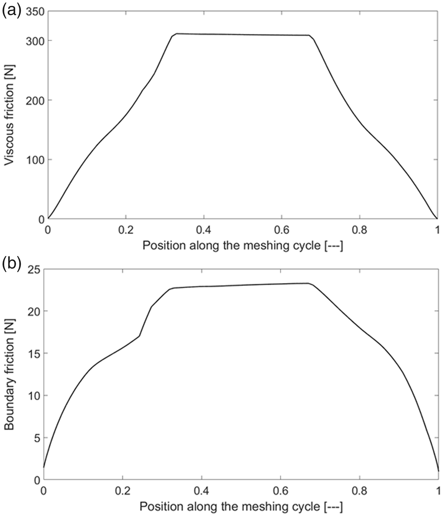
Figure 6 shows the dominance of viscous friction contribution to frictional heat generation. Considering the contribution of the both viscous and boundary friction, Figure 7 shows the estimated total frictional power loss for a meshing cycle for the mid-velocity condition. The effects of a leading and trailing meshing teeth pairs are considered in the determination of the total power loss. The average power loss for this gear pair is 1.13 kW.
Meshing cycle power loss.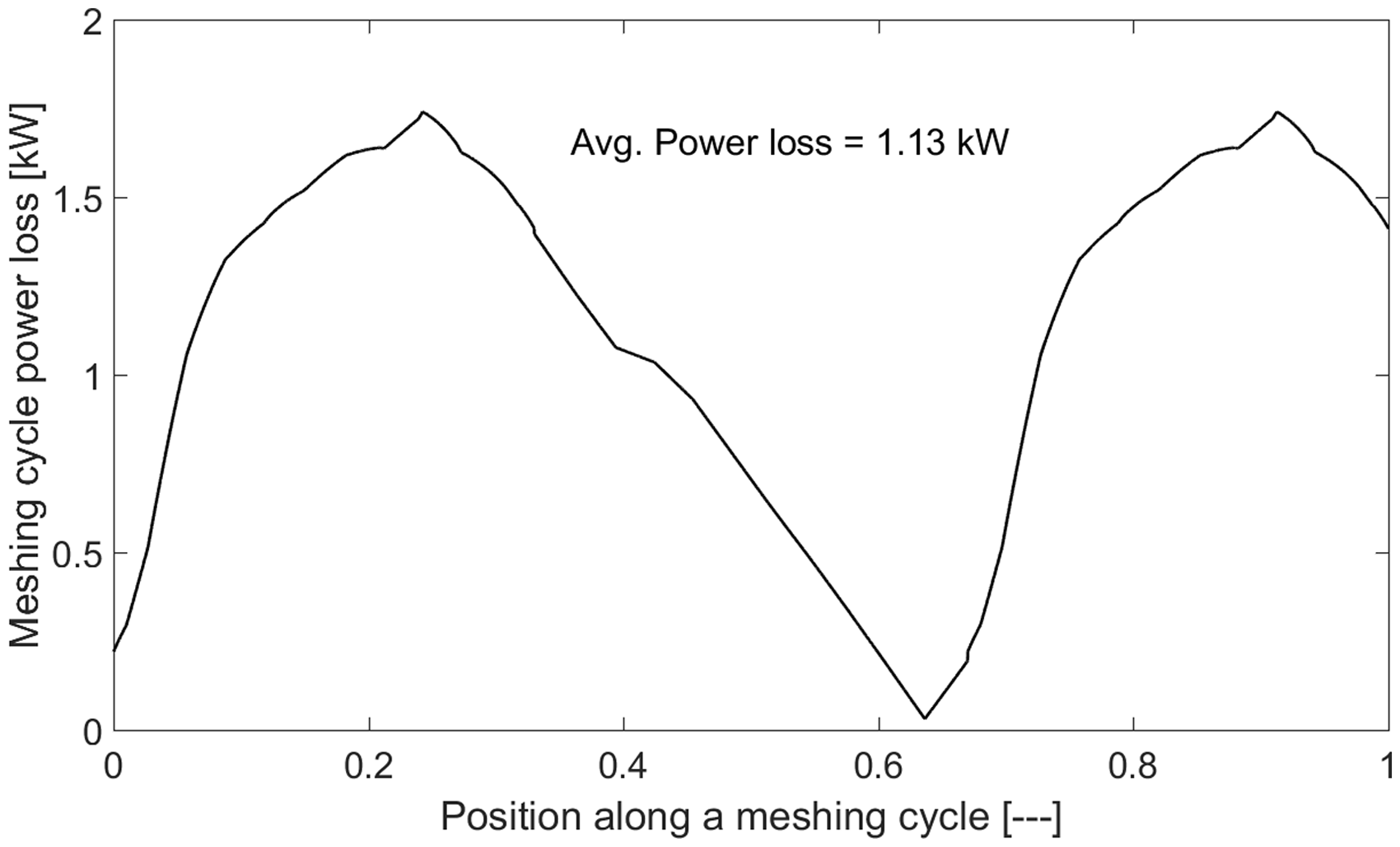
In each rotation of the gear, when in mesh, the average power loss is obtained based on the real operating conditions. It is assumed that the generated heat in the contact is conducted equally to the two meshing gear teeth surfaces. 33 Thus, 565 W is conducted per tooth flank in the current study. Heat dissipation through convection that forms a very thin elastohydrodynamic lubricant film is negligible. 28 The average heat transfer coefficient from the gear teeth and body can now be obtained using the 3D CFD model (Figure 3). The determined generated heat (i.e. power loss) and heat transfer coefficients are input into the FE model.
For the race lap conditions shown in Figure 4, the average power loss is applied onto the contacting flank during periods of meshing of the 7th gear pair. This means that for the periods which the gear pair is unselected (i.e. not in contact), only convection heat dissipation from the gear surfaces is happening. The average surface temperature of contacting teeth flank is presented in Figure 8.
Average surface temperature variation on a contacting tooth flank.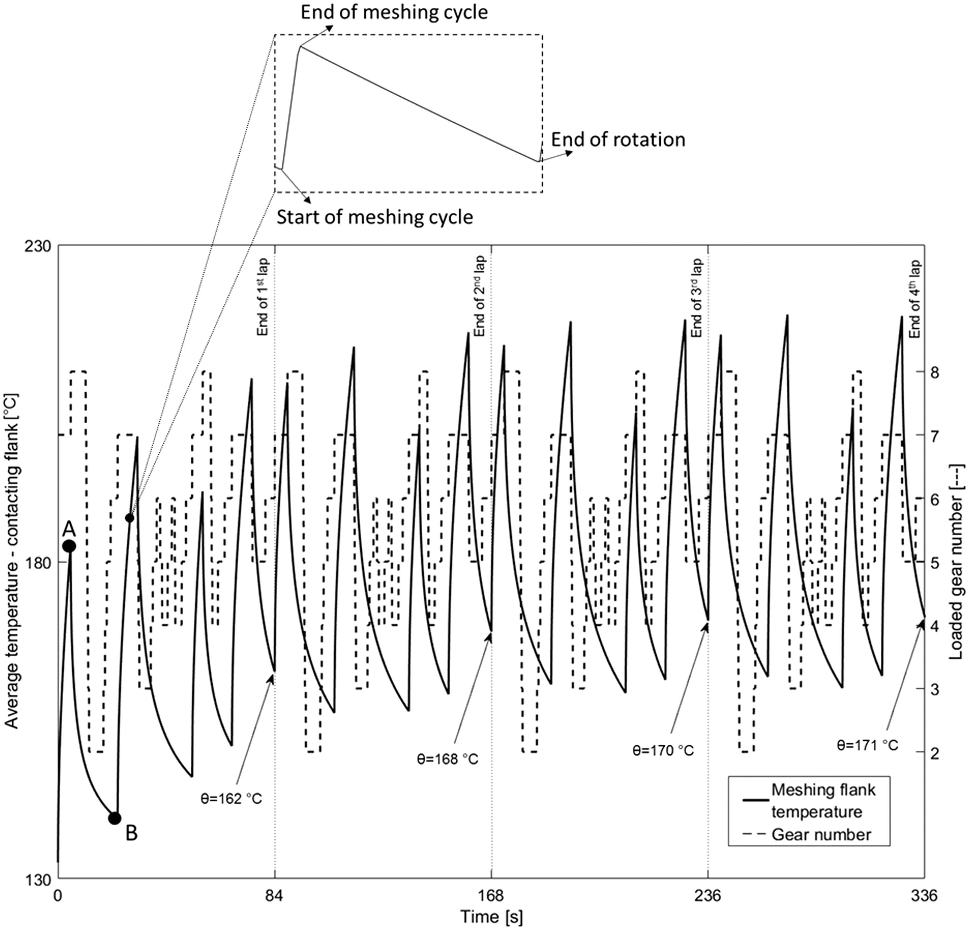
Figure 8 shows that the temperature variation on a contacting flank gets repetitive during every racing laps and almost reaches steady-state equilibrium after four racing laps. The figure also shows that during periods of gear engagement the flank temperature rises sharply as a result of the generated heat. Subsequently, for any gear disengagement period, the heat is convected to the ambient as the dominant heat transfer mechanism. At the start of disengaged periods, the temperature difference between the gear flank and the ambient (i.e. the transmission housing at 130 ℃) is the highest. Approaching the end of disengaged periods, the rate of temperature drop decreases slightly as the temperature difference with the ambient and therefore the rate of convection heat transfer is decreased.
Figure 9 shows the total quantity of convected heat from a tooth segment (Figure 3) for the same period as in Figure 8.
Total convection heat transfer from the tooth segment for each gear rotation.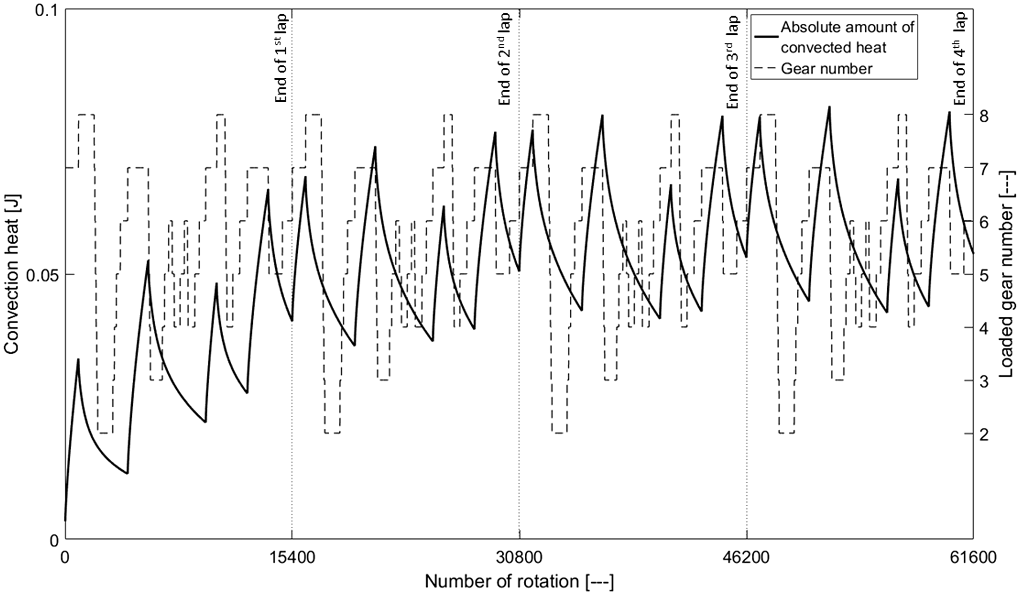
During the gear disengagements, the rate of total heat convection to the ambient rises due to higher contact temperature. Referring to Figures 8 and 9, the higher the temperature rise, the higher the temperature difference is with the ambient environment of the transmission casing, therefore, the greater the heat dissipation through convection heat transfer.
Figure 10 illustrates the temperature counters of a tooth segment for the specified points on Figure 8. Point A marks the end of an engaged period, whilst point B corresponds to the end of a disengaged period.
Counters of temperature at (a) point A and (b) point B in Figure 8.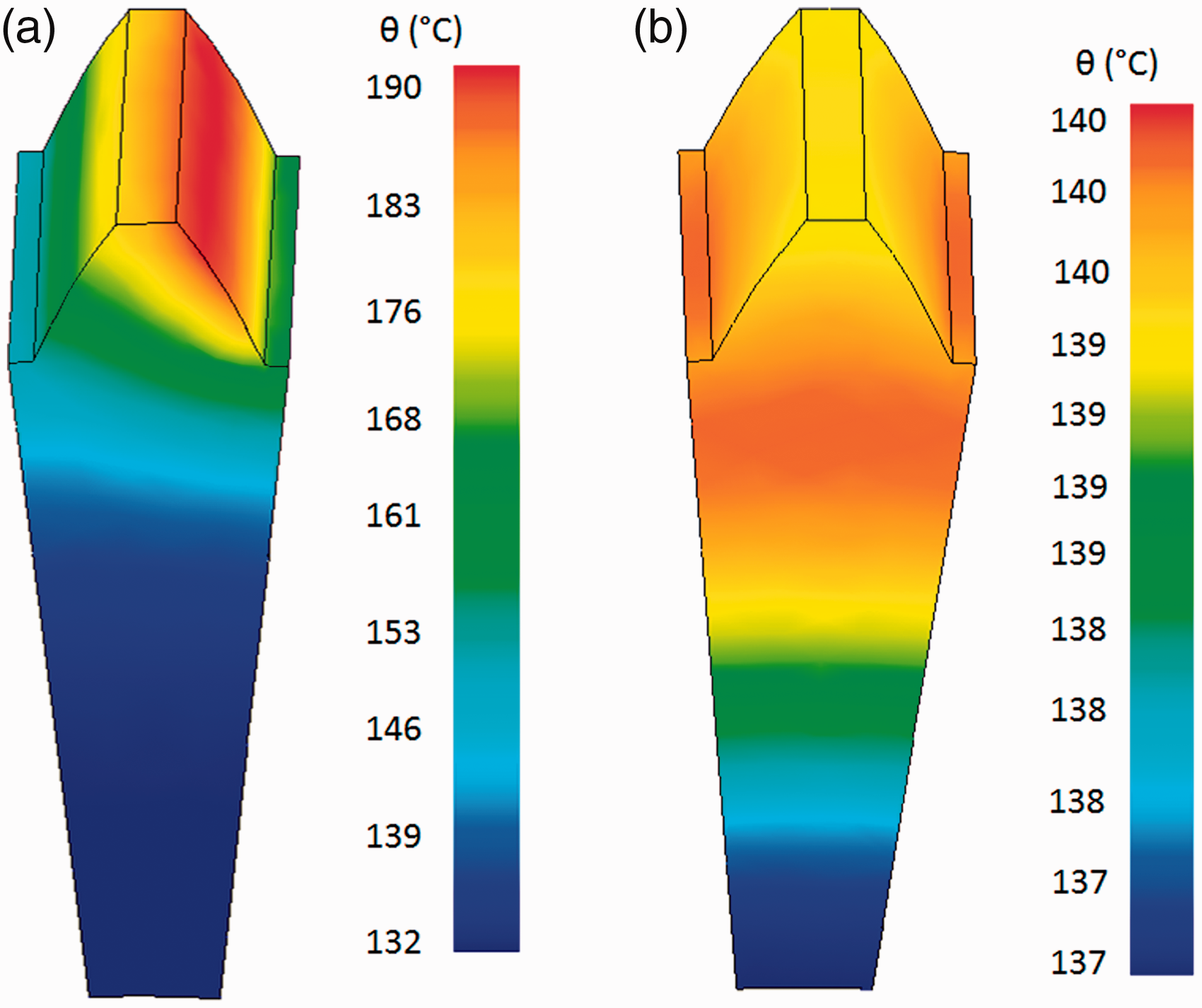
When the gear is in contact (Figure 10(a)), the heat generation rate is approximately two orders of magnitude higher than the rate of convection cooling. Therefore, the difference in contacting flank temperature and other gear surfaces becomes significant. However, during disengagement (Figure 10(b)), convection cooling becomes dominant. Consequently, temperature is almost the same for all the different gear surfaces (i.e. the difference between maximum and minimum temperature is merely 3 ℃).
Figures 11 shows the counters of convection heat flux from the tooth segment for the same specified points in Figure 8.
Counters of convection heat flux from the tooth segment at (a) point A and (b) point B in Figure 8.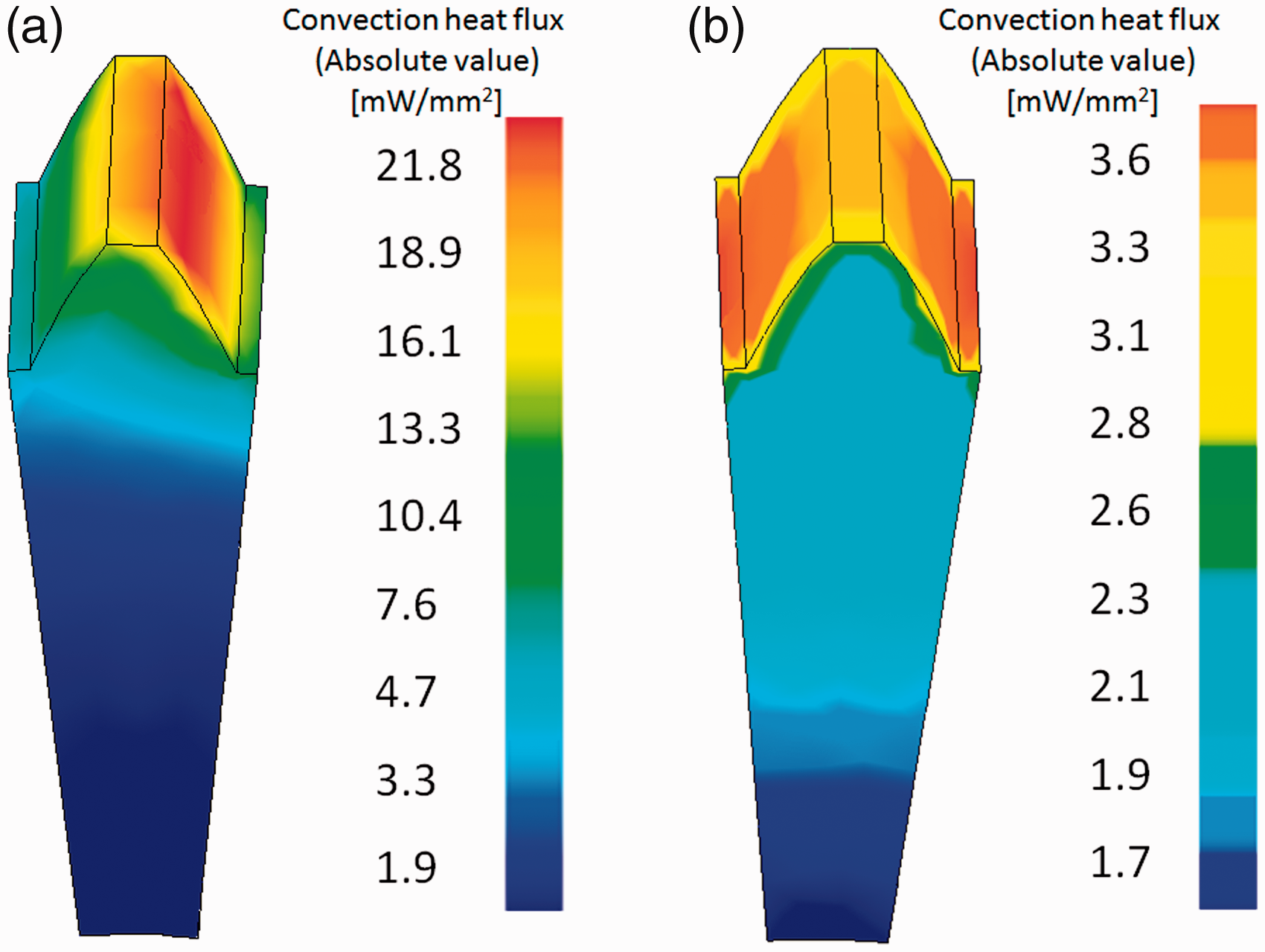
Figure 11 shows that during the gear meshing period (Figure 11(a)) the convection heat flux from a contacting flank increases due to the higher tooth surface temperature, caused by friction-induced heat generation. However, convection heat flux from different surfaces of the tooth segment during periods of unengaged gear (Figure 11(b)) is fairly uniform. The gear tooth, directly facing the impinging cooling oil jet and its heat transfer coefficient are higher compared with the gear body. Therefore, the heat flux from the gear tooth is higher than that from the gear body itself.
Conclusion
Previous thermal analyses of jet-lubricated transmission systems lack requisite accuracy. In this study, a transient integrated multi-disciplinary numerical model of gear contacts in dry sump transmission is presented. The aim is to predict the thermal steady-state temperature variation of the system. The proposed model incorporates a component level TCA model, a tribological gear teeth pair meshing model and a CFD model for a gear pair system within a FE overarching model. This is to evaluate the quantity of generated heat as well as the heat removal rate from the rotating gear surfaces. Transient heat transfer and temperature distribution through a gear tooth segment, lubricated by an impinging oil jet of high performance racing application is investigated. The proposed model is capable of simulating the transient behaviour of the transmission systems for a wide range of operational conditions, predicting the steady-state temperature fluctuations of the system.
The following conclusions are made:
For the presented race conditions, it is shown that it takes four cycles for the longest engaged gear pair to attain thermal equilibrium. The rate of convection heat transfer from gear surfaces is higher during engaged gear periods. This is due to an increase in the temperature difference between the gear surface and the ambient environment of the transmission casing. The meshing flank temperature sharply reduces at the start of any gear disengagement since the gear faces the cooling oil jet. Consequently, the convection heat transfer to the ambient remains the only heat transfer mechanism. The generated heat in the contact can be dissipated through convection cooling by a single impinging oil jet. However, the jet must spray continuously, including during the disengaged gear periods in order to ensure the overall steady-state behaviour of the temperature variation over race laps. The predictions enable optimum design of dry sump lubrication systems to ensure the availability of a sufficient but not excessive oil flow rate through a directed impinging jet.
Footnotes
Acknowledgement
The authors thank the ANSOL company for supplying the CALYX software, which was utilised for TCA analysis in this study.
Declaration of Conflicting Interests
The author(s) declared no potential conflicts of interest with respect to the research, authorship, and/or publication of this article.
Funding
The author(s) received no financial support for the research, authorship, and/or publication of this article.