
Abstract
High-end graphics processing units (GPUs), such as NVIDIA Tesla/Fermi/Kepler series cards with thousands of cores per chip, are widely applied to high-performance computing fields in a decade. These desktop GPU cards should be installed in personal computers/servers with desktop CPUs, and the cost and power consumption of constructing a GPU cluster platform are very high. In recent years, NVIDIA releases an embedded board, called Jetson Tegra K1 (TK1), which contains 4 ARM Cortex-A15 CPUs and 192 Compute Unified Device Architecture cores (belong to Kepler GPUs). Jetson Tegra K1 has several advantages, such as the low cost, low power consumption, and high applicability, and it has been applied into several specific applications. In our previous work, a bioinformatics platform with a single TK1 (STK platform) was constructed, and this previous work is also used to prove that the Web and mobile services can be implemented in the STK platform with a good cost-performance ratio by comparing a STK platform with the desktop CPU and GPU. In this work, an embedded-based GPU cluster platform will be constructed with multiple TK1s (MTK platform). Complex system installation and setup are necessary procedures at first. Then, 2 job assignment modes are designed for the MTK platform to provide services for users. Finally, ClustalW v2.0.11 and ClustalWtk will be ported to the MTK platform. The experimental results showed that the speedup ratios achieved 5.5 and 4.8 times for ClustalW v2.0.11 and ClustalWtk, respectively, by comparing 6 TK1s with a single TK1. The MTK platform is proven to be useful for multiple sequence alignments.
Introduction
High-end graphics processing units (GPUs), such as NVIDIA Tesla/Fermi/Kepler series cards, became very popular for high-performance computing fields in a decade. Many desktop GPU cards contain up to thousands of cores per chip, for example, a NVIDIA Tesla K80 GPU card has 4992 Compute Unified Device Architecture (CUDA) cores (belong to Kepler GPUs). They contain massive multithreaded processors and can be executed concurrently to fully use the GPU computing power. However, these desktop GPU cards should be installed in personal computers/servers with desktop CPUs. The cost and power consumption of constructing a GPU cluster platform with these desktop CPUs and GPU cards are very high. For example, it may spend more than $10 000 to buy a personal computer with a NVIDIA Tesla K80 GPU card and a kilowatt-class power supplier. Therefore, for most of the research institutes, it is hard to construct a GPU cluster platform based on personal computers/servers with multiple desktop GPU cards.
Jetson Tegra K1 (TK1) released by NVIDIA is a full-featured platform for embedded applications and it contains 4 ARM Cortex-A15 CPUs, 192 CUDA Cores (belong to Kepler GPUs), and 2 image signal processing cores. The cost of a single TK1 is less than $300 and its power consumption is about tens of watts by the tests. 1 Moreover, TK1 has several advantages, such as the low cost, low power consumption and high applicability, by comparing with other embedded platforms,2,3 desktop CPUs,1,4 and desktop GPU cards. 4 For example, Wolfer 3 presented the results that a single TK1 outperforms a Raspberry Pi Model in terms of time and speedup ratios; Paolucci et al 1 proved that the dual-socket node connected by TK1s achieves 14.4 times better than that by SuperMicro server with Intel XEON E5620 CPUs for the power consumption; and Fu et al 4 showed the results that the power efficiency and cost efficiency by a single TK1 are both better than those by an Intel i7-3770 CPU and a NVIDIA GTX 690 GPU card. Hence, it becomes a new research direction to study TK1s in several specific applications, such as the surveillance, bioinformatics, and image processing.
Compute Unified Device Architecture 5 could access GPUs as a graphic Application Programming Interface and has made the supercomputing available to the mass. In the past, many parallel algorithms, programs, and tools have been developed using CUDA based on desktop GPU cards. For example, in the bioinformatics field, several CUDA-based tools, such as MUMmerGPU, 6 CUDA-MEME, 7 and CUDA-BLASTP, 8 have been proposed. ClustalW 9 is a well-known multiple sequence alignment tool, which is used to align a set of sequences by repeatedly (or called progressively) aligning pairs of sequences and previously generated alignments according to the orders in a phylogenetic (or called guide) tree. In our previous work, 10 a CUDA version of ClustalW v2.0.11, called CUDA ClustalW v1.0, has been proposed using the intratask parallelization 11 on a single-GPU or multiple-GPU card(s). For the overall execution time, CUDA ClustalW v1.0 based on a single NVIDIA Tesla C2050 GPU card can achieve more than 33 times speedup ratio by comparing with ClustalW v2.0.11 based on an Intel XEON X5550 CPU.
In our previous work, 12 we have constructed a mobility and acceleration computing platform for the bioinformatics field based on a single TK1 (STK platform). Because there is no famous or automatics install package designed for a single TK1, many preparation procedures should be done before using the computing power of the STK platform, such as the refresh system image, setup network, and install necessary software. After that, CUDA ClustalW v1.0 tool was ported to the STK platform, called ClustalWtk, by recompiling the source codes of CUDA ClustalW v1.0 and replacing several functions used in the ARM CPU instead of the Intel CPU. ClustalW v2.0.11 was also ported to the STK platform by a similar way to compare it with ClustalWtk. ClustalWtk based on the STK platform can achieve 3 times speedup ratio by comparing with ClustalW v2.0.11 based on an Intel XEON E5-2650 CPU; ClustalWtk based on the STK platform can achieve 4 times speedup ratio by comparing with ClustalW v2.0.11 based on an ARM Cortex-A15 CPU. In addition, for ClustalWtk, the cost-performance ratio by the STK platform is higher than that by a NVIDIA Tesla K20 GPU card. The Web and mobile services for ClustalWtk with user-friendly interfaces also were provided in our previous work.
However, the computing power of the STK platform still is limited and not good enough. For example, in the experimental tests, 12 the execution time by ClustalWtk on the STK platform is 5 times than that by CUDA ClustalW v1.0 on a NVIDIA Tesla K20 GPU card although the number of CUDA cores on a NVIDIA Tesla K20 GPU card is 13 times than that on a single TK1. Therefore, in this article, an embedded-based GPU cluster platform is constructed based on multiple TK1s (MTK platform). There are 2 advantages of constructing the MTK platform. The first one is to enhance the computing power of STK platform, even equal to that of a desktop GPU card. The second one is to reduce the construction cost of a GPU cluster by comparing that with desktop GPU cards.
The construction of MTK platform can be separated into 2 parts: hardware and software. In the hardware part, multiple TK1s and a 100-MB router should be installed and set up. For the software part, there are 3 phases should be done, including the single TK1 setup, multiple TK1s setup, and the job assignment mode design. The single TK1 setup phase is similar to the system setting up part in our previous work. 12 After this phase, the multiple TK1s should be managed using the “master-slave” model in the multiple TK1s setup phase. However, still there is no famous or automatic install package designed for multiple TK1s. Hence, the master-slave model of multiple TK1s is built by setting the network environment and the file system. For a cluster platform as the MTK platform, many computations (or called tasks) could be assigned to various computing units (CPUs or GPUs) by a task schedule tool to enhance the throughput. In the job assignment mode design phase, 2 job assignment modes, one is “user selected” mode and another is “automatic assigned” mode, are designed in the MTK platform. The user can assign the task(s) to a specific TK1 using the user selected mode, whereas all the tasks can be assigned evenly and automatically to multiple TK1s using the automatic assigned mode. To evaluate the MTK platform, both ClustalW v2.0.11 and ClustalWtk are ported to the MTK platform, and then the experimental results showed that the speedup ratios achieved 5.5 and 4.8 times for ClustalW v2.0.11 and ClustalWtk, respectively, by comparing 6 TK1s with a single TK1. The MTK platform is proven to be useful for multiple sequence alignments.
The rest of this article is organized as follows. Preliminary concepts used in this article are introduced in section “Preliminary Concepts.” Section “Platform Construction” presents the details of constructing the MTK platform. Platform implementation and experimental results are given in section “Experimental Results.” Conclusions are drawn in section “Conclusions.”
Preliminary Concepts
ClustalW and ClustalWtk
ClustalW 9 is a progressive multiple sequence alignment tool and 3 steps are involved in it, including the distance matrix calculation, guide tree creation, and progressive alignment. In the first step “distance matrix calculation,” each pair of biological sequences are used to calculate the similarity score by a pairwise alignment algorithm, such as Needleman and Wunsch algorithm, 13 and then these similarity scores are formed as a distance matrix for all biological sequences. When aligning m biological sequences with an equal length of n by ClustalW, m2/2 pairwise alignments should be done, and then, the total time complexity is up to O(m2n2). Therefore, the computation time of the first step occupied most of overall execution time by ClustalW. 14 In the second step “guide tree creation,” a guide tree is built from the distance matrix calculated in the first step using a phylogenetic tree construction algorithm, such as the unweighted pair group method with arithmetic mean. 15 The orders of following third step are determined by the guide tree built in the second step. In the third step “progressive alignment,” each pairwise alignment result is generated by a pairwise alignment algorithm according to the orders in the guide tree at first, and then, it is combined with the previously generated alignments. In our previous work, 12 ClustalW v2.0.11 was ported and executed in the STK platform.
ClustalWtk 12 is modified from CUDA ClustalW v1.0 10 and also can be executed in the STK platform. In ClustalWtk, the step “distance matrix calculation” is implemented on Kepler GPUs, and several optimization methods were designed to enhance the performance by ClustalWtk. Other steps “guide tree creation” and “progressive alignment” are implemented on ARM Cortex-A15 CPUs. For m biological sequences, ClustalWtk used the intratask parallelization to assign each pairwise alignment to a thread block. In a thread block, a pairwise alignment is implemented by the type “Synchronous Diagonal Multiple Threads” defined by Lin and Lin. 16 In addition, for ClustalWtk, several optimization methods, such as the load-balancing strategy and memory allocation, were also designed for the distance matrix calculation step. The details of implementation of ClustalWtk can be found in our previous work.10,12 However, there are several errors, and system environment should be corrected and set up when ClustalWtk is compiled on the STK platform. Moreover, the performance by ClustalWtk on the STK platform could be tuned to obtain the best computing ability. The details of program porting and performance tuning for ClustalWtk also can be found in our previous work. 12
Asynchronous JavaScript and XML
Asynchronous JavaScript and XML (AJAX) is a combination technique of Web site development technologies. The traditional Web application will send a request (with a transmitted data) to the Web server after the user completes the required form. The Web server will receive and process the transmitted data and then will send back a new Web page for the Web application. This way will waste a lot of network bandwidth and time. Asynchronous JavaScript and XML was proposed by Jesse James Garrett. 17 The difference between AJAX and a traditional Web site technology is that AJAX can only send the necessary information (for a request) to the Web server and use JavaScript in the front-end interface to deal with the server response without a new Web page. The need for the network bandwidth is reduced significantly, and the server response time is shorter than that by the traditional Web site technology. Therefore, many tasks can be done on the user equipment by AJAX, and it provides a better user experience to speed up the processing time. Browserscope 18 is a well-known community-driven project for profiling Web browsers. In Browserscope, the network performance for each Web browser is listed, and we can find that the maximal number of connections, which means that each Web browser connects to the server with same host name, is limited to 6 to 8. Asynchronous JavaScript and XML can simultaneously perform multiple asynchronous data transmission; hence, in this article, AJAX is used to design the application interface and execute the commands on the background among multiple TK1s.
Network Address Translation
Network Address Translation (NAT) 19 is a technique of rewriting the source or destination IP address when an IP packet passes through a router or firewall. Network Address Translation can solve the shortage problem of IPv4 address and avoid the difficulty of keeping IP addresses. Network Address Translation is widely used in multiple hosts but only has 1 entity IP (or called public IP) address. To access the Internet in a private network, it can set the IP addresses of multiple hosts to private IP addresses and then connect them to the Internet via an NAT server (or router) with a public IP address. Network Address Translation has been widely used in home routers and its main feature is to build a subnetwork. When a packet in a subnetwork needs to be sent to an external network, it must be converted via an NAT router; similarly, a package in an external network must also be converted via an NAT router to reach the hosts within a subnetwork. In this article, the MTK platform consisted of multiple TK1s, and NAT is a necessary technique to confirm that all the TK1s are set up in the same domain, and each TK1 will receive a specified private IP address.
Network File System
Network File System (NFS) is a distributed file system protocol and originally developed by Sun Microsystems. 20 Network File System allows users to access (or share) the files on various machines or operating systems through the network as a file server. Network File System is an open standard defined in “Request for Comments” (RFC) 21 now, and RFC allows anyone to implement this protocol. In this article, NFS is used to access files in the MTK platform by each TK1. All the resources (or files) are put in the shared folder of “Master” TK1. Other “Slave” TK1s can access these files through NFS (see section “Setting NFS”).
Secure Shell Protocol
Secure Shell Protocol (SSH) is formulated by IETF’s Network Working Group. 22 In the traditional delivery technique in a network, it did not have the password to deliver files and accounts, so it can be attacked easily. Secure Shell Protocol is a security agreement based on the application layer and transport layer of network protocol and allows users to login other computer host through the network remote operation. When using SSH login, each host should enter the account number and its corresponding password. However, the password can be omitted when the technology “ssh-keygen” is used. The key generator will create a public key to corresponding private key and then the user can do the login without the password. In this article, the technology “ssh-keygen” is used to allow users to login each TK1 more conveniently. Secure Shell Protocol also encrypts and compresses all transmitted data as a packet and then delivers the packet to the network. Therefore, SSH can prevent network information security issues, such as the DNS spoofing and man-in-the-middle eavesdropping. In addition, the compressed transmitted data will increase the transmission speed. OpenSSH is a famous open-source free software, and it is a default installation in a single TK1. In this article, OpenSSH is used for the communications among multiple TK1s.
Platform Construction
In this article, the MTK platform is constructed based on multiple TK1s, and the construction of MTK platform can be separated into 2 parts: hardware and software. In the hardware part, there are 7 TK1s and a 100-Mb router is installed and set up in the MTK platform. The router should support the NAT technique, and it is used to connect these 7 TK1s. Each TK1 receives a specified private IP address from the router, and 1 of 7 TK1s is set up as a “Master,” each of others (6 TK1s) is set up as a “Slave” (or called Client). In the MTK platform, the Master TK1 is used to manage the Slave TK1s and the Slave TK1s are used to do the computations. For the software part, there are 3 phases, including the single TK1 setup, multiple TK1s setup, and the job assignment mode design. The details of implementation of each phase will be described in the following sections.
Single TK1 setup phase
In this phase, there are 3 steps: (1) operating system installation, (2) internet connection setting, and (3) compile environment setting. In the first step “operating system installation,” the system image and device driver for “Linux for Tegra” (L4T) R21.1 are downloaded from NVIDIA Developer Zone 23 (now for an updated version R21.2). After device driver is decompressed, the system image should be placed in the child directory “rootfs” at first. Then, the file “apply_binaries.sh” should be executed. A micro USB cable is connected between a single TK1 and a Linux PC host. When a single TK1 has successfully connected with a Linux PC host, the command “sudo ./flash.sh -S 14580MiB jetson-tk1 mmcblk0p1” is executed, and then, the default account and password are used to login the L4T. A single TK1 can be operated directly or remotely. Hence, the keyboard, mouse, and HDMI screen can be used when they are connected directly to a single TK1 or using the OpenSSH service after the Internet connection is set up. Because L4T operating system is modified based on Ubuntu 14.04, the system settings of L4T are the same as those of Ubuntu 14.04. For the second step “Internet connection setting,” it can modify the network parameter settings file placed in the directory “/etc/network/interfaces” and then execute the command “sudo ifdown -a && sudo ifup –a” to reload the network parameter settings file, as shown in Figure 1. In the third step “compile environment setting,” several files, tools, and modules should be installed in a single TK1. For example, the version of CUDA 6.5 should be installed on a single TK1; Gcc, G++, Apache, PHP, mail server, and Qt4 may be installed in a single TK1 according to the application requirements. Due to the descriptions of this step are similar to those illustrated in our previous work, 12 the details of this step are omitted in this article.
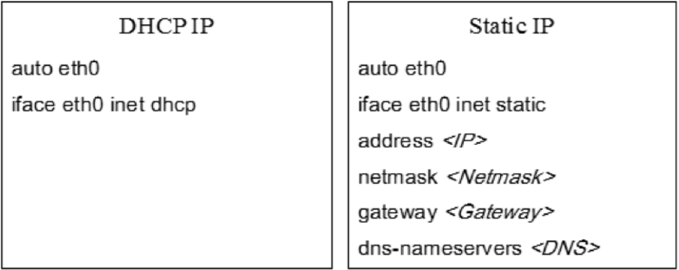
The format of network parameter settings file.
Multiple TK1s setup phase
After the first phase to set up each TK1, the next step is to manage multiple TK1s using the “master-slave” model in the second phase “multiple TK1s setup.” However, still there is no famous or automatic install package designed for multiple TK1s. Hence, this phase can be separated into 3 steps, including (1) setting SSH, (2) setting subnetwork, and (3) setting NFS. In the following sections, these 3 steps are described in detail.
Setting SSH
As mentioned in section “Secure Shell Protocol,” it will be more convenient to let the Master TK1 login into other Slave TK1s without the password. This way is also useful for the design of “automatic assigned” mode illustrated in section “Job assignment mode design phase.” The goal in this step is to generate a pair of public key (defined as id_rsa.pub) and private key (defined as id_rsa) using the RSA method at first. Then, the private key is stored in the Master TK1, and the public key is copied to each Slave TK1. Finally, a verification file (defined as authorized_keys) is generated with the public key for each Slave TK1.
The details of implementation actions are described below:
Action 1. Generate a pair of public key (id_rsa.pub) and private key (id_rsa) in the Master TK1 using the command “ssh-keygen-t rsa.” The default settings are used.
Action 2. Add the public key from the Master TK1 into each Slave TK1. For example, it can be done using the command “scp ~/.ssh/id_rsa.pub node2:~/.ssh/” to add the public key into a the directory “ ~/.ssh/” of a Slave TK1 (defined as a “node2” in section “Setting subnetwork”).
Action 3. Create a verification file “authorized_keys” in each Slave TK1 by using the command “touch ~/.ssh/authorized_key.”
Action 4. Add the public key (id_rsa.pub) to the verification file “authorized_keys” in each Slave TK1 using the command “cat ~/.ssh/id_rsa.pub >> ~/.ssh/authorized_keys.”
Setting subnetwork
As mentioned in section “Network Address Translation,” multiple TK1s can be connected as a subnetwork using an NAT router. There are 2 ways to do this step. The first one is to set up the Master TK1 with a public IP address and a private IP address and only to set up each Slave TK1 with a private IP address. By this way, the Master TK1 can be communicated with the Internet (or user) and each Slave TK1. Another way is only to set up the Master TK1 and Slave TK1s with private IP addresses and then to set up the Master TK1 as the DMZ (Demilitarized Zone) by an NAT router. By this way, the packet in the Internet (or user) only can be sent to the Master TK1 through an NAT router. The architecture diagrams of these 2 ways are shown in Figure 2. In addition, the names, “node1,” “node2,” and etc, are also used for the Master TK1 (as a “node1”) and Slave TK1s (as the “node2” to “node7”) to identify them easily. These private IP addresses and names of the Master TK1 and Slave TK1s are added into the file “/etc/hosts” copied in each TK1.

Architecture diagrams of setting subnetwork: (A) public IP + private IP and (B) private IP + NAT. NAT indicates Network Address Translation.
The details of implementation actions are described below:
Action 1. Login into each TK1 (Master and Slave) to get its corresponding IP address using the command “ifconfig eth0.”
Action 2. Add the IP address and name of each TK1 into a file “/etc/hosts.” In the Master TK1, the file “/etc/hosts” is edited by the command “sudo vim/etc/hosts” with the role of administrator “root.” In the Slave TK1, the file “/etc/hosts” is also edited as that in the Master TK1. In the file “/etc/hosts,” all the IP addresses and names obtained from each TK1 are added.
Setting NFS
As mentioned in section “Network File System,” the files placed in the Master TK1 can be accessed by the Slave TK1s through the NFS protocol. The goal in this step is to install the NFS protocol into the Master TK1 (as a server) and each Slave TK1 (as a client) at first. Then, a shared folder (defined as “/mirror”) is created by the Master TK1. Finally, this shared folder can be accessed by other Slave TK1s.
The details of implementation actions are described below:
Action 1. Install the NFS protocol in the Master TK1 using the command “sudo apt-get install nfs-server.”
Action 2. Install the “nfs-common” in each Slave TK1 using the command “sudo apt-get install nfs-common.”
Action 3. Set the shared folder “/mirror” of Master TK1 using the command “echo “/mirror*(rw,sync)” | sudo tee -a/etc/exports.”
Action 4. Create a folder “/mirror” in each Slave TK1 using the command “sudo mkdir/mirror.”
Action 5. Mount the shared folder “/mirror” of Master TK1 for each Slave TK1 using the command “sudo mount node1:/mirror/mirror.” When this step is done successfully, each file in the shared folder of Master TK1 will be listed in the folder of each Slave TK1.
Job assignment mode design phase
After the above 2 phases, the MTK platform has been constructed based on multiple TK1s. However, for a cluster platform as the MTK platform, many computations (or called tasks) could be assigned to various computing units (CPUs or GPUs) by a task schedule tool to enhance the throughput. Unfortunately, there is no famous task schedule tool designed for multiple TK1s. Hence, in this article, 2 job assignment modes have been designed for the MTK platform using the Web site form and JavaScript according to the user’s requirements. For the Web site design, several computer languages and techniques, such as HTML, PHP, jQuery, and AJAX, are also used. In the Web site, we can use the “jquery file upload plugin” to upload the files (tasks). The open-source code for this plugin can be found in the GitHub (https://github.com/). After that, the user can assign tasks to Slave TK1s according to the job assignment mode. The first job assignment mode, called “user selected,” is a simple method to assign the task(s) to a specific Slave TK1 by the user. After selecting the specific Slave TK1, AJAX as mentioned in section “Asynchronous JavaScript and XML” will execute the command and call PHP to do the SSH2 connection. SSH2 will connect to a selected Slave TK1 and then the tasks are executed in it.
Another job assignment mode, called “automatic assigned,” is a rule-based task schedule method (without the load-balancing strategy now) to check the number of tasks and the number of computing units (TK1s). Because the maximal number of connections for various Web browsers is limited in 6 to 8, the number of tasks per round is set up to 6 in this article. When the user assigns tasks to Slave TK1s according to the automatic assigned mode, the Master TK1 will execute the automatic assign method to assign a task to a Slave TK1 (6 Slave TK1s in the MTK platform) under the restriction (6 tasks per round). When the number of tasks is less than 6, all the tasks can be assigned to Slave TK1s in a round. When the number of tasks is larger than 6, the first 6 tasks will be assigned to 6 Slave TK1s at first and then 1 of the reminder tasks will be assigned to a Slave TK1 when the previous assigned task in it is completed. Until all the tasks are completed, the process of automatic assign method in the Master TK1 will be stopped. The pseudocode of automatic assigned method is listed below.
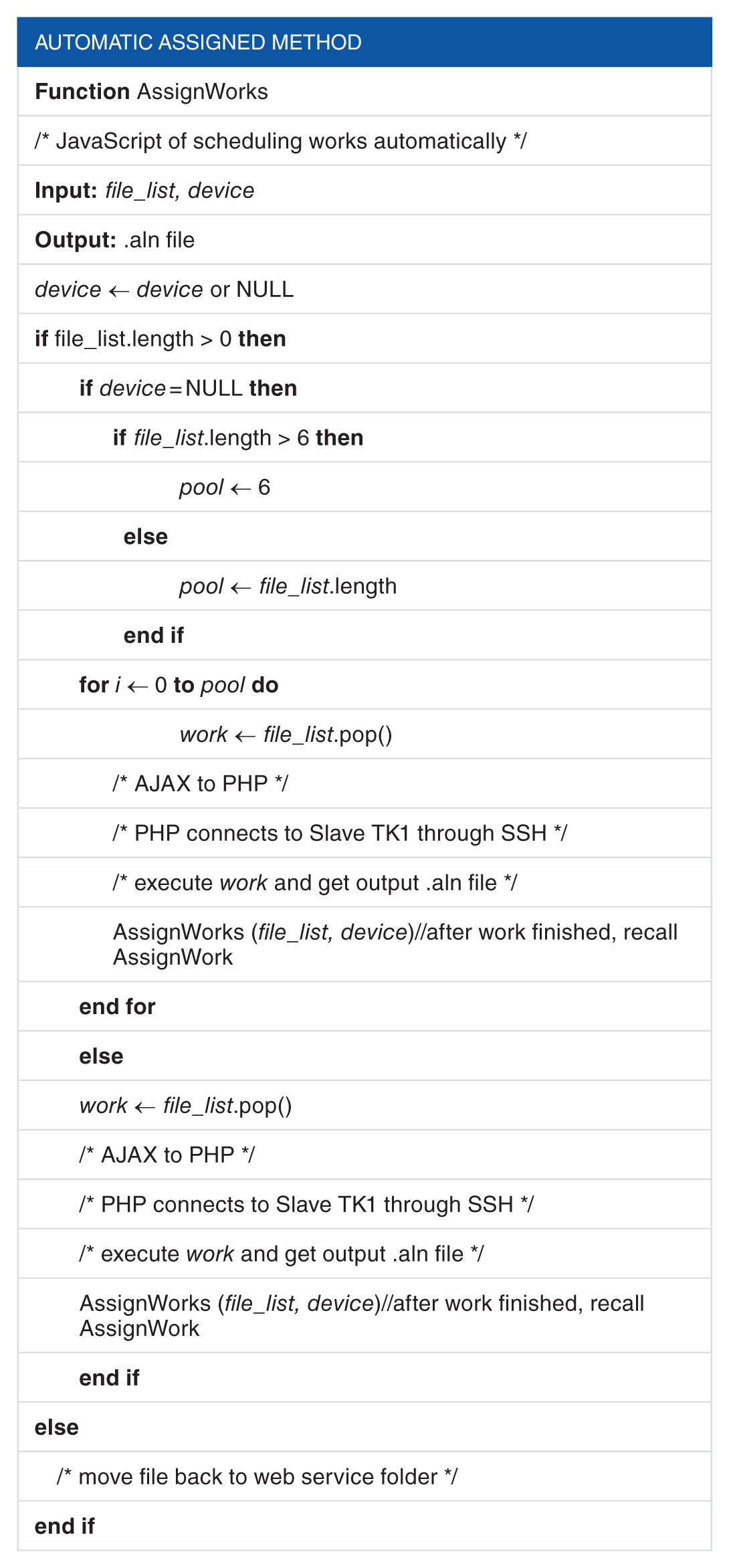
In the automatic assigned method, a queue (defined as “file_list”) is used to extract (or called pop) the tasks using the “First In First Out” rule. When the automatic assigned method is executed, the function “AssignWorks” will be called, and the AJAX will execute the command and call PHP to do the SSH2 connection. SSH2 will connect to Slave TK1s and then the tasks are executed in them. When a task in a Slave TK1 is completed, the callback function of AJAX will be used to call the function “AssignWorks” again to do the assignments until all the tasks are completed. When applying the automatic assigned method for ClustalWtk, the schematic diagram of calling AJAX, PHP, and SSH in the MTK platform is shown in Figure 3, and the flowchart of automatic assigned method is shown in Figure 4.
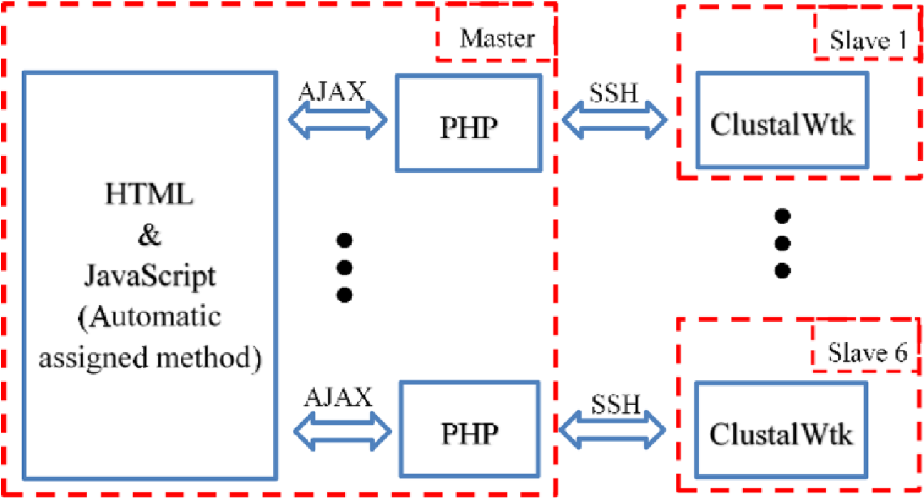
The schematic diagram of calling AJAX, PHP, and SSH in the MTK platform. AJAX indicates Asynchronous JavaScript and XML; SSH, Secure Shell protocol.

The flowchart of automatic assigned method.
Experimental Results
In this article, the MTK platform was constructed based on 7 TK1s (1 for the Master TK1 and others for Slave TK1s) and a 100-MB NAT router. To evaluate the MTK platform, ClustalW v2.0.11 and ClustalWtk were both ported and then used to do the experimental tests. As mentioned in section “Job assignment mode design phase,” 2 job assignment modes have been designed for the MTK platform in this article, and for each job assignment mode, it is implemented in a Web site, built using HTML, PHP, jQuery, and AJAX, with ClustalW v2.0.11 and ClustalWtk. For the MTK platform, the tasks are used to do the multiple sequence alignments for biological sequences. The test protein sequences 10 were downloaded from the National Center for Biotechnology Information Web site (www.ncbi.nlm.nih.gov/), and these sequences can be classified into 8 test sets: (t1) 100 sequences with length of 97, (t2) 100 sequences with length of 498, (t3) 100 sequences with length of 1002, (t4) 100 sequences with length of 1523, (t5) 1000 sequences with length of 97, (t6) 1000 sequences with length of 498, (t7) 1000 sequences with length of 1002, and (t8) 1000 sequences with length of 1523.
For the user selected mode, the Web site with ClustalW v2.0.11 and ClustalWtk was shown in Figure 5. In Figure 5, the user can upload a test set to the Web site at first. Then, the user can select ClustalW v2.0.11 (run on CPU) or ClustalWtk (run on GPU) to do the multiple sequence alignment for the uploaded test set. When selecting ClustalW v2.0.11, it will be executed by an ARM Cortex-A15 CPU of a specific TK1; when selecting ClustalWtk, it will be executed by the Kepler GPUs of a specific TK1. Finally, the user can select 1 of the 7 TK1s to do the task. The alignment result will be stored as a text file and then the user can open this file to see the result.

The Web site with ClustalW v2.0.11 and ClustalWtk using the user selected mode.
For the automatic assigned mode, the Web site with ClustalW v2.0.11 and ClustalWtk was shown in Figure 6. In Figure 6, the user can upload more than one of the test sets to the Web site at first. After uploading the test sets, the Web site will create a list with all the tasks; each task has a task name and original file name (.fsa file). Then, the user can select ClustalW v2.0.11 (run on CPU) or ClustalWtk (run on GPU) to do the multiple sequence alignments for all the uploaded test sets. When selecting ClustalW v2.0.11, it will be executed by an ARM Cortex-A15 CPU of each Slave TK1; when selecting ClustalWtk, it will be executed by the Kepler GPUs of each Slave TK1. Finally, the Master TK1 will execute the automatic assign method to assign tasks to 6 Slave TK1s. When a task is assigned to a Slave TK1 with a running state or a task is in a waiting state, this task can be stopped and deleted by the user. After a task is completed, it will be removed from the list shown in the Web site. When all the tasks are completed, the Web site will create a list with all of tasks; each task has a task name and a file name with the alignment result (.aln file). The user also can open this file to see the result.
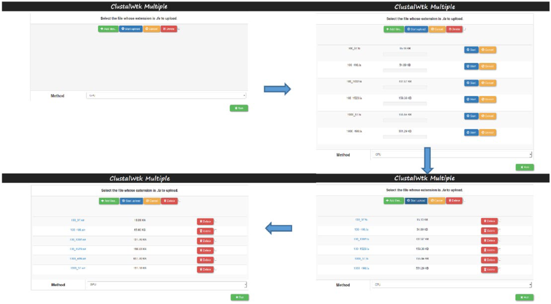
The Web site with ClustalW v2.0.11 and ClustalWtk using the automatic assigned mode.
For the automatic assigned mode, a test was also done to evaluate the MTK platform in this article. In this test, for 8 test sets, each test set is divided into 6 equal parts at first. Then, for each test set, each part can be seen as a task and all the 6 parts (as 6 tasks) are uploaded to the Web site to be executed concurrently by ClustalW v2.0.11 or ClustalWtk (the MTK platform). In addition, for each test set, all the 6 parts also are executed one by one by ClustalW v2.0.11 or ClustalWtk on the STK platform. The execution time (unit: second, represented by log10) by ClustalW v2.0.11 and ClustalWtk based on the STK and MTK platforms is shown in Figure 7, respectively. In Figure 7, the “Cluster(CPU)” and “Cluster(GPU)” mean that ClustalW v2.0.11 and ClustalWtk are executed on 6 Slave TK1s, respectively (the MTK platform); similarly, “Single(CPU)” and “Single(GPU)” mean that ClustalW v2.0.11 and ClustalWtk are executed on a single TK1, respectively (the STK platform). When comparing the MTK platform with the STK platform, from Figure 7, for 8 test sets, we can see that the execution time by ClustalW v2.0.11 and ClustalWtk on the MTK platform is less than that on the STK platform. The speedup ratios achieved 5.5 and 4.8 times for ClustalW v2.0.11 and ClustalWtk, respectively, by comparing the MTK platform with the STK platform. Because more extra computations in the GPU are needed, the speedup ratio by ClustalWtk is not larger than that by ClustalW v2.0.11 (only for ARM CPU).

The execution time by ClustalW v2.0.11 and ClustalWtk based on the STK and MTK platforms.
When comparing the computing power by the ARM Cortex-A15 CPU and Kepler GPUs in the MTK platform, from Figure 7, we also can see that the execution time by ClustalW v2.0.11 is less than that by ClustalWtk for the test sets with small sequence lengths (t1 and t2). The reason is that the computation costs for these sets are too small and are not useful for the GPU computing. For other test sets (t3-t8), the execution time by ClustalWtk is less than that by ClustalW v2.0.11. For test set t8 with a large sequence length, the speedup ratio can achieve 4.4 times by comparing ClustalWtk with ClustalW v2.0.11 on the MTK platform.
Conclusions
In this article, the MTK platform was constructed based on multiple TK1s to enhance the computing power of the STK platform and reduce the construction cost of a GPU cluster. The details of system installation and setup were presented in this article. Moreover, 2 job assignment modes, user selected and automatic assigned, were designed in the MTK platform. ClustalW v2.0.11 and ClustalWtk were both ported in the MTK platform, and these 2 tools were used to evaluate the performance of the MTK platform with the automatic assigned mode. By the experimental results, the speedup ratios achieved 5.5 and 4.8 times for ClustalW v2.0.11 and ClustalWtk, respectively, by comparing the MTK platform with the STK platform. Besides, the speedup ratio can achieve 4.4 times by comparing ClustalWtk with ClustalW v2.0.11 on the MTK platform. These results are used to prove that the MTK platform is useful for multiple sequence alignments.
Footnotes
Acknowledgements
The authors would like to thank the anonymous reviewers and experts discussed with them in the past.
Peer Review:
Two peer reviewers contributed to the peer review report. Reviewers’ reports totaled 134 words, excluding any confidential comments to the academic editor.
Funding:
The author(s) disclosed receipt of the following financial support for the research, authorship, and/or publication of this article: Part of this work was supported by the Ministry of Science and Technology under the grant MOST105-2221-E-182-067.
Declaration of Conflicting Interests:
The author(s) declared no potential conflicts of interest with respect to the research, authorship, and/or publication of this article.
Author Contributions
JDW, HJC, and CYL conceived the idea of this manuscript. HJC, JY, and KYY designed and carried out the experiments. JDW, CYL, and JY analyzed the data. JDW, HJC, CYL, and KYY wrote the manuscript. All authors read and approved the final manuscript.