
Abstract
The Totally Implantable Envoy® System is currently undergoing clinical trials in both the United States and Europe. The fully implantable hearing device is intended for use in patients with sensorineural hearing loss. The device employs piezoelectric transducers to sense ossicle motion and drive the stapes. Programmable signal processing parameters include amplification, compression, and variable frequency response. The fully implantable attribute allows users to take advantage of normal external ear resonances and head-related transfer functions, while avoiding undesirable earmold effects. The high sensitivity, low power consumption, and high fidelity attributes of piezoelectric transducers minimize acoustic feedback and maximize battery life (Gyo, 1996; Yanagihara, (1987) and 2001). The surgical procedure to install the device has been accurately defined and implantation is reversible.
Introduction
Acoustic or conventional hearing aids use an externally worn microphone and an amplifier that drives a speaker (receiver) positioned in the ear canal. A semi-implantable hearing device also uses an external microphone and amplifier, but vibrates the ossicular chain directly through a surgically installed driver. A fully implantable hearing device has all three elements (sound sensor, amplifier, and driver) surgically implanted.
A conventional hearing aid activates the ossicular chain by driving the air between the device speaker and the tympanic membrane. Impedance mismatch at this interface results in reduced transmission of transient sounds. This increases the number of interfaces between the input sound and ultimate the motion of the stapes. Most conventional hearing aids, and some semi-implantable aids, also require that a tightly fitting earmold be positioned in the external ear canal to prevent acoustic feedback. In many cases, this results in discomfort, promotes cerumen buildup, and in extreme cases, can lead to necrosis of ear canal tissue. Furthermore, the presence of an earmold results in an occlusion effect. Patients find this occlusion annoying, and the earmold negates the functional properties of the pinna and external ear canal (Middlebrooks et al., 1989). Sound localization is reduced by the presence of the occluding device and the 20 to 25 dB of external auditory canal gain is lost (Shaw, 1966).
While well-fit completely-in-the-canal hearing aids may partly ameliorate occlusion effects, a fully implantable hearing system completely avoids these deficits. Not only are the pinna and ear canal allowed to function in a normal manner, but sensing sound vibrations via the ossicular chain also eliminates earmold effects and reduces possibilities for acoustic feedback. In addition, driving the stapes directly has theoretical advantages with regard to improved sound quality, greater output, and reduced distortion (Luetje et al., 2002; Hough et al., 2002). A totally implantable device has the advantage of being visually undetectable, which to many individuals is cosmetically desirable. Additionally, it offers many environmental benefits that may provide significant lifestyle improvements, such as the ability to hear while bathing and swimming. There may also be improvements in comfort and hygiene compared to semi-implantable and traditional hearing aids, which may promote eczema or otitis externa.
Various research groups have worked on developing semi-implantable and fully implantable hearing devices over the past 30 years, with varying degrees of success (see Goode et al., 1995, for a review). Driver technologies range from devices that vibrate the ossicular chain electromagnetically (Goode and Glattke, 1973; Maniglia et al., 1997), to devices that drive the chain via an electric “shaker” (Lenarz et al., 1998), and devices that incorporate piezoelectric drivers (Yanagihara et al., 1987). Each technology has strengths and weaknesses. Eliciting ossicle vibration through electromagnets requires that the driving and driven magnets be in very close proximity since magnetic field strength diminishes rapidly with distance. Driving the chain via a shaker element adds mass to the system, which in clinical trials has been shown to slightly attenuate the transmitted sound signal (Gan, 2001). The use of piezoelectric transducers requires custom circuit design.
Envoy System Technology
The Envoy System developed by St. Croix Medical is a fully implantable hearing device that uses piezoelectric transducers. The implanted components of the Envoy System are shown in Figure 1. The Sensor and Driver are connected via leads to the Sound Processor header. The Sensor (bottom) is used to sense vibration from the incus and the Driver (top) is used to drive the stapes.

Implanted components of the Envoy System. The Sound Processor is connected via removable leads to the Driver transducer (top) and the Sensor transducer (bottom).
Piezoelectric devices consist of specially formulated crystals that deform when electrical voltage is applied to them or, alternatively, produce an electrical voltage when deformed. Thus, they are transducers in the literal sense, converting one form of energy into another—reversibly. The most suitable piezoelectric transducers are built as a “bimorph” in which two crystals are sandwiched together, effectively multiplying the deformation. Greatest output occurs when the transducer is formed in the shape of a cantilever with one end fixed and the other mobile. The principal advantages of piezoelectric devices are very low power consumption, small size, high sensitivity, and low distortion. These properties make them ideally suited for use in implantable hearing devices (Kodera, 1988).
While both electromagnetic and piezoelectric transducer technologies are potentially suitable for implantable devices, the circuits to drive the transducers are very different. Piezoelectric transducers are voltage driven, whereas electromagnetic transducers and hearing aid receivers are current driven. In fact, implantable electromagnetic drivers may be driven rather well by existing hearing aid circuits. This is because both require high current and low voltage. Piezoelectric transducers, on the other hand, require moderate voltage and negligible current. A piezoelectric driver driven with a hearing aid circuit can only deliver 90 to 100 dB SPL. This was the scenario for the Yanagihara, Gyo and Suzuki device produced by Rion in Japan. The limitation was not due to the piezoelectric transducer, but rather to the hearing aid circuit and transcutaneous coupling of the semi-implantable device, which further decreased the drive voltage (Ohno T, 1988). With custom circuit design and more sophisticated transducer design, piezoelectric devices can deliver more than 120 dB SPL (Figure 2).

Stapes footplate displacement in a fresh human temporal bone. The lowest trace is the normal intact chain stapes displacement with a 100 dB SPL stimulus in the ear canal. The middle trace shows the stapes displacement when driven by a piezoelectric driver with a 1-volt pp stimulus (approximately the same as a hearing aid battery). The upper trace shows the stapes displacement driven by the driver with a 10-volt pp stimulus.
Figure 2 shows stapes footplate displacement data from a fresh human temporal bone. The bottom trace is the normal intact chain stapes displacement with a 100 dB SPL stimulus in the ear canal. The middle trace shows the stapes displacement when driven by a piezoelectric driver with a 1-volt pp stimulus (approximately the same as a hearing aid battery). The upper trace shows the same stapes and driver relation, but driven with a 10-volt pp stimulus. There are three messages contained in the plot: (1) Piezoelectric drivers can effectively drive the stapes with broad bandwidth and smooth physiological frequency response; (2) Hearing aid batteries and associated circuits limit the output of piezoelectric devices to approximately 100 dB SPL; (3) Piezoelectric drivers can achieve output levels of more than 120 dB SPL (130 dB SPL at 4 kHz) when driven with an appropriate voltage. The real advantage of piezoelectric transducers is that the current is nearly negligible. Because power is equivalent to voltage times current, the overall power consumed by a piezoelectric driver is still nearly negligible. Piezoelectric transducer power consumption is a few microwatts, whereas electromagnetic transducer/receiver power consumption is on the order of a milliwatt. The power difference is a factor of between 100 and 1000.
Figure 3 shows a schematic of the Envoy's piezoelectric Driver in position within the middle ear and mastoid. The Driver tip is attached to the head of the stapes while the base is fixed to the mastoid floor. When the Driver is stimulated with an electrical signal, the piezoelectric transducer bends, creating a piston-like movement in the stapes. A comparison of stapes displacement for the acoustically driven normal intact chain and the piezoelectrically driven stapes is shown in Figure 2. Patients with this type of piezoelectric driver have described this sound as “more natural” (Yanagihara, 2001).

Schematic of the Envoy Driver in position within the middle ear. The Driver tip is attached to the head of the stapes and the base to the mastoid floor.
The Envoy System's Sensor transducer is attached to the body of the incus, as shown in Figure 4. Sound pressure collected by the tympanic membrane is transferred to the malleus and incus, where the Sensor picks up the vibration. In effect, the tympanic membrane serves as the microphone diaphragm. The Sensor generates a voltage proportional to the incus vibration. This process is analogous to a phonograph needle picking up the vibration in a record track. A small amplifier at the base of the transducer matches the high impedance of the transducer to the lower impedance of the amplifier circuitry, thereby improving energy transfer and decreasing electromagnetic interference susceptibility.

Schematic of the Envoy Sensor in position within the middle ear. The Sensor tip is attached to the incus and the base to the mastoid floor.
Attaching the Sensor to the body of the incus makes it possible to leave the external auditory canal open and, more importantly, take advantage of the free gain and filtering. With the Envoy System, the pinna and external ear canal collect sound in the normal manner, which produce a pressure amplification of 20 to 25 dB in the speech frequency range and enables the head-and pinna-based filtering that permits sound localization in the median plane.
Several implementation issues exist for sensors positioned on the incus. Among these are a naturally occurring decrease in incus displacement with increasing frequency (Goode et al., 1994) and frequency-dependent changes in the rotational axis of the malleus-incus complex (Gyo et al., 1987). St. Croix Medical did considerable development work using sensors implanted in human temporal bones to minimize these effects and arrive at the “optimal” sensing site.
The amplified voltage generated by the sensor is routed to a custom-built signal processor, termed the Sound Processor. The Sound Processor contains electronic circuitry, a bidirectional telemetry antenna, and a battery. The electronic circuitry consists of signal processing, telemetry, power supply management, patient information memory, and tone generating circuits. The Sound Processor is housed in a hermetically sealed titanium enclosure (see Figure 1). In designing the application specific integrated circuit (ASIC), special attention was given to employing extreme low-power circuit design techniques. The lithium-iodine “pacemaker-type” battery is expected to last up to five years assuming 16 hours of daily use. The patient is alerted of a low battery condition by a change in the acknowledgement signal (a beep) each time a parameter such as volume is changed. The Sound Processor may be easily replaced under local anesthesia.
All parameters (filtering, amplifier gain, compression ratio, etc.) are adjustable from outside the head using the Commander programmer. The Commander consists of software running on a laptop and a hand-held wand that communicates with the Sound Processor via telemetry (Figure 5). Using the Commander software, the audiologist fitting the device determines the desired settings and communicates these to the sound processor via the wand. The system may be repeatedly re-programmed as necessary to optimize system performance. Additionally, the Sound Processor has a built-in tone generator used for diagnostic purposes to evaluate system performance. The audiogram-like output is termed an Envoygram.
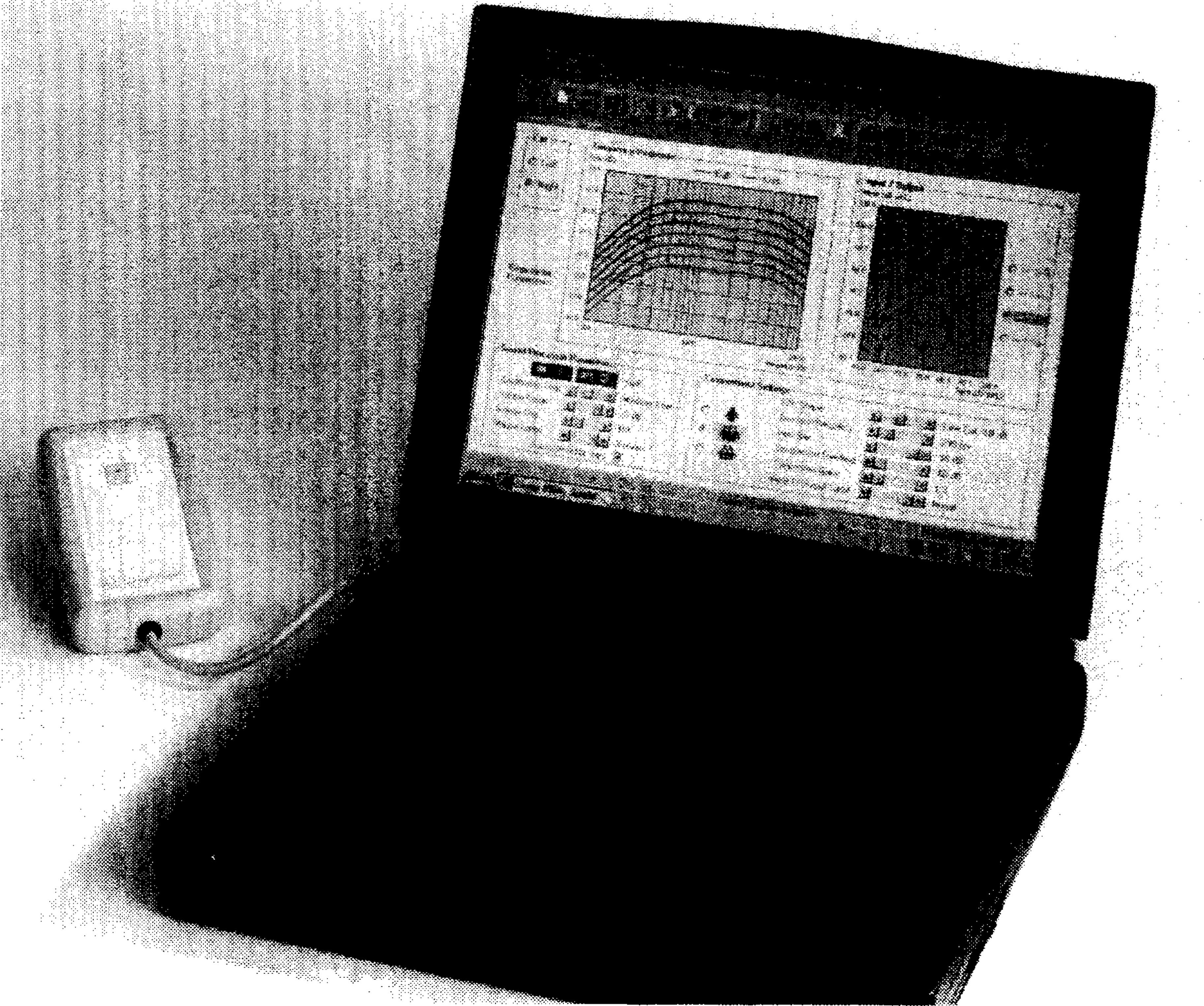
The Envoy Commander Programmer (laptop, software and telemetry wand).
The patient has control over the system through the Personal Programmer (Figure 6). The Personal Programmer features on/off and volume control, and a choice of three programmed environment settings.

The Envoy System's Personal Programmer, which provides patients with a volume control, on/off button, and choice of three programmable environmental settings.
Theoretically, a feedback potential exists in the Envoy System as well in conventional or semi-implantable hearing aids. The feedback-inducing pathway could arise from electrical coupling, air conduction, or bone conduction. Fortunately, all of these pathways are of sufficiently low amplitude so as to not be a factor in limiting the gain. Specifically, insulating and/or shielding of the Sensor, Driver and connecting leads greatly reduces the possibility of feedback via electrical coupling. Acoustic coupling caused by the Driver transmitting airborne vibrations to the Sensor is of exceptionally low amplitude and is therefore not a contributor to feedback. The most significant source of feedback is Driver vibration being transmitted to the Sensor via bone conduction. However, peak feedback magnitude has been measured in the vicinity of −60 dB, which is low enough that sufficient headroom exists for a large functional gain.
Surgical Technique
The surgical procedure is as follows: A postauricular flap is raised the size of which is similar to that created as part of the installation of a cochlear implant. A standard mastoidectomy is then performed. Preparation for installing the transducers is completed by opening the facial recess in the usual manner. A bed is created in the cortex posterior to the mastoid cavity to house the Sound Processor, similar to the depression created for a cochlear implant electronics package.
A laser or malleus nipper is used to remove 2 to 3 mm from the long process of the incus. A temporary stabilizing arm (Glasscock stabilizer) is attached to the mastoid cortex just behind the sigmoid sinus, and the Driver is attached to the other end of the stabilizer. The stabilizer is flexible and allows the surgeon to manipulate the Driver into position over the head of the stapes in a matter of seconds. Once in position, the legs of the Driver are covered with hydroxyapatite cement to bond it to the mastoid floor. The cement is allowed to set, after which the stabilizing arm is removed from the Driver. Finally, a drop of glass ionomeric cement is applied to the head of the stapes to bond it to the Driver tip.
The Sensor is then attached to the Glasscock stabilizer. The Sensor is manipulated into position so that the transducer tip lies in contact with the incus body just posterior to the malleus-incus joint. Like the Driver, the legs of the Sensor are covered with hydroxyapatite cement to anchor it to the mastoid floor, followed by a drop of glass ionomeric cement at the transducer tip to incus interface. The stabilizer is then removed.
Once the Sensor and Driver have been installed, both are tested to make sure they are functioning properly. An acoustic signal is introduced into the external ear through an insert earphone, and the resulting Sensor voltage is measured and recorded. The Driver is then stimulated electrically at various intensities and auditory brainstem responses (ABRs) are obtained. The postimplant ABR and preimplant ABR latencies are compared to verify proper function. In addition to these measures, laser Doppler vibrometer (LDV) measurements of stapes motion can also be taken.
The leads from the Sensor and Driver are then inserted into the header of the Sound Processor, and the processor is secured by means of sutures or titanium straps. Final complete system testing is performed with a sound stimulus in the ear canal and ABR output, or optionally, an LDV output measurement of the stapes. A schematic of the complete installation is shown in Figure 7.

Schematic of the completed Envoy installation. The insert shows a magnified view of the relationships of Sensor and Driver transducers to the ossicular chain.
One major concern with implantable devices is how well they can be removed if the patient desires. In the Envoy System, repair of the resected incus would be required. Because the incus is not removed during device installation, it is possible to reconstruct the incudostapedial joint using conventional techniques. The incus can be repaired with a number of prostheses or ionomeric cement. Temporal bone testing has shown that hearing through the cement reconstructed joint should be within 5 to 10 dB of the original audiometric thresholds, and hearing at high frequencies may even be improved (Maassen, 1998; Grant, 2001).
The Envoy System is initially activated six to eight weeks after the surgery, when sequalae of opening and manipulating the middle ear have resolved.
Discussion
Driving the ossicular chain directly via piezoelectric transducers is an efficient method of transferring sound information to the cochlea. The utility of piezoelectric drivers has been demonstrated repeatedly since the early 1970s. For example, Yanagihara et al., (1987) developed a partially implanted device using an external microphone and a piezoelectric transducer to the head of the stapes. Over 60 patients were implanted and all reported improved quality of sound. Kodera et al., (1994) showed that speech discrimination scores in six patients averaged 10% better than scores achieved by those patients through conventional hearing aids. Once again, patients reported that sounds presented through the implant possessed greater fidelity than what they had experienced using conventional hearing aids. In other studies, patients with a mild-to-moderate hearing impairment experience improved speech discrimination when the ossicular chain is directly driven; the improvement is evident in noise and holds true for music and environmental sounds as well as for speech (Luetje CM, 2002; Hough JV, 2002; Hough JV, 2001).
The aforementioned research led St. Croix Medical to adopt piezoelectric transducer technology in its development of the totally implantable Envoy System. The totally implantable attribute provides advantages in comfort, cosmesis, and allows patients to use the device in environments such as swimming in which traditional and semi-implantable devices cannot be used. The system employs a semi-biologic microphone using the tympanic membrane as the microphone diaphragm, similar to what occurs in normal hearing, which makes it more physiological. Unlike external microphones, the Envoy System retains the benefits of the normal resonance of the ear canal and takes advantage of the head-and pinna-related filtering that permits sound externalization and localization in the median plane. Temporal bone testing has shown that the driver and electronic circuitry are capable of providing output power exceeding 120 dB SPL. The low power consumption of piezoelectric transducers translates into an expected battery life of up to five years.
The Envoy Fully Implantable Hearing System may offer a promising alternative to patients with sensorineural hearing impairment. Detailed clinical data on human performance is currently being accrued as part of the clinical trials being performed in Europe and the United States.