
Abstract
In the current vehicle development process, the suspension friction is commonly treated as a constant force, while other suspension parameters, such as stiffness and damping, are quantified according to the actual kinetic state. Even though this simplification might be approximately true for many suspension variants, the theoretical background and the experiments conducted in this study indicate that the suspension friction of a MacPherson system is strongly subject to change depending on the forces and moments acting at the tyre contact patch. On the other hand, there is only a limited research basis quantifying to what extent suspension friction is affecting vehicle behaviour during various driving events. Therefore, assessments of whether an often-urged friction reduction is appropriate in the context of developmental efforts and benefits are equally limited. The first reasonable step is to accurately determine the actual amount of suspension friction regarding various boundary conditions and load situations, which currently is not constituted in literature. Hence, within the frame of the present study, the friction under various influences is investigated for a compact car, beginning at the full suspension and with special focus on lateral forces and combined wheel deflection states. While certain influences (engine state, excitation amplitude in a limited range) seem to be of minor importance, the suspension friction is strongly affected by various forces and moments at the tyres and by the wheel deflection level, whereas the lateral force dependence is mostly distinctive.
1. Introduction
Vehicle characteristics are a complex interaction of various subsystem properties. The suspension design constitutes a major influence regarding the vertical vehicle dynamics, especially in terms of ride comfort (Angrick et al., 2015). Therefore, a precise knowledge of the mechanisms and interrelations is essential for defining the transmission behaviour of the suspension, which in turns determines the dynamics.
Next to the kinematic aspects or unsprung masses, the stiffness and damping properties, both primary and secondary, are of great importance for the transmission of road unevenness to the vehicle body. The fundamental dependencies of these parameters are widely known (Koch et al., 2015; Troulis, 2002), as are the interrelation of various suspension elements (Lohse, 2016; Stretz, 2011) and their effect on the vehicle behaviour (Bedük et al., 2018; Kaldas et al., 2012; Phalke and Mitra, 2017), which is typically treated as an optimization problem (Jayachandran and Krishnapillai, 2012; Kaldas et al., 2014). But in order to predict vehicle behaviour more accurately in the future, further research is necessary to assess the required level of detail (Bedük et al., 2018).
The adequate definition and inclusion of component friction is potentially located in this improvement process. It is still state of the art of vehicle dynamics prediction in automotive development to consider suspension friction as a constant value, being independent of the kinetic situation and the boundary conditions. Subsequently, it has not been sufficiently investigated which driving situations would benefit from an enhanced description of suspension friction properties. This indicates that the effect of suspension friction on vehicle vertical dynamics for certain road events is not investigated fully either, as can be observed from the following studies. (Yabuta et al., 1981) was one of the first to study suspension friction in interrelation with other parameters and stated that its effect on the ride comfort depends not only on the amount of friction, but on the road quality, the tyre stiffness and the driving speed. He pointed out that friction could be particularly detrimental on smooth roads and at low speeds. (Manger, 1995) came to a similar conclusion, stating that the friction impact on poor roads and at high speeds is small, which was concluded from the observance of an increasing influence of friction for smaller amplitudes. While higher friction generally decreased ride comfort, advantageous effects on the dynamic wheel load variation were observed in the range of the unsprung mass eigenfrequency. (Cormie and Stolarski, 1986) focused on the effect of shock absorber friction for passing single obstacles. They concluded that friction actually supports the motion damping (resulting from the flow of the hydraulic medium), but hinted at the general adverse effects on ride comfort as well. (Geluk, 2005) found a shift of the unsprung mass vertical resonance to higher frequencies on higher quality roads in an experimental set-up, explaining the results with an increased suspension stiffness in the shock absorber’s stick phase. From the background of magneto-rheological shock absorbers, where friction is potentially increased due to metallic particles in the hydraulic fluid, (Fujimoto et al., 2018; Komori et al., 2017) investigated the friction effect on the transfer behaviour between the wheel and body acceleration in a simulation and experimental test set-up. They found out that the gain was reduced especially in the range of 3–8 Hz for lower friction amounts, which is a sensitive area regarding human perception (ISO2631-1, 1997). Similar findings were presented earlier by (Ilosvai and Szücs, 1972; Yabuta et al., 1981). Other research also dealt particularly with high-frequency friction phenomena focusing on noise effects (Kruse and Zimmermann, 2002).
Unfortunately, the aforementioned studies intending to link suspension friction and vertical dynamics were performed in a more or less general manner instead of being specific for certain real road events with a clear quantification of the friction effect.
Another issue worth mentioning is the very small number of studies presenting actual, reliable data regarding the amount of friction for the suspension. This applies to the whole suspension as well as specific components of it and is also relevant for studies exploring the multiple parameters (e.g. temperature and amplitude) the friction might depend on. Failing to list a clear definition of the boundary conditions worsens the problem. In the study of (Wegener, 2020), friction values of front and rear axles of various vehicles are listed. In it, a high variation of friction values from 75–350 N is noticeable, but no information on the boundary conditions are provided. These values highly exceed those determined in the frame of the following presented experiments – at least regarding a state without any additional forces and moments and of typical wheel load, as described later. Similarly, the amount of shock absorber friction is listed from (Fujimoto et al., 2018) at approx. 20–150 N (extracted from a diagram) depending on the shock absorber version. (Manger, 1995) provides shock absorber friction amounts of 30–45 N, while (Kölsch, 1994) speaks of 25 N without any additional normal force-increasing loads. An interesting study on friction by (Angrick et al., 2015) provides information on the amplitude dependence and on the component participation on the overall suspension friction of a multilink suspension. While all values are relative, no absolute friction amounts are listed.
Potential reasons for the limited number of studies and research might be (1) the necessity of extensive measurements to determine friction accurately and with a high level of reproducibility, (2) the high effort in modelling friction accurately and (3) the arising difficulties concerning the practical validation of a performed friction variation in terms of vehicle dynamics. Moreover, there is no standard existing in order to give a definite framework for friction determination on any level (component and subsystem), as is the case, for instance, for shock absorber (damping) testing using the well-known VDA procedure.
Nevertheless, the mentioned studies clearly note that there is some effect of friction on vehicle dynamics, which is predominantly described as adverse and which makes it necessary and legitimate to conduct further studies.
The starting point to contribute to solving the presented superordinate, interrelated scientific issue should be to investigate suspension friction for various load cases in order to gather information on the friction dependencies, interrelations and the development under certain conditions assigned to typical driving events. In parallel, it is necessary to study the effect of suspension friction on the vertical dynamics for desired road events, for example, in the frame of a simulation. This includes an extended concept of the friction value as a function of the suspension kinetic state, which makes the before-mentioned investigation necessary. Finally, it was possible to assess which situations (depending on road event, type of vehicle and remaining suspension plus vehicle parameters) require a certain extension of the consideration of suspension friction.
By conceptualizing the ride comfort phenomenon specifically and not generalized, and by considering it in the context of customer’s requirements, a quantitative basis is created for the suspension developer to decide to what extent it is necessary and appropriate to reduce suspension friction, comparing development expenses and actual dynamics improvement.
While the described comprehensive issue is fully in the author’s broader research scope, this paper only deals with the presentation of friction measurements on the subsystem level (suspension level). Ongoing studies will strive to provide a link to the component level in order to give insight into the effect mechanism leading to a potentially varying suspension friction.
2. Theoretical background
The suspension system consists of various components and it is therefore reasonable to assume various sources of friction contributing to the total suspension value. Friction arises from elastomer bushings, ball joints and of other contact surfaces, where relative motion takes place. Because the suspension investigated in this study is a spring-strut type suspension, special consideration of the (twin-tube) shock absorber is needed, as it fundamentally contributes to the wheel control and is assembled together with the spring. Because of this, in the planar view (y-z-plane), the tyre contact patch (TCP) forces Outer forces at a spring-strut suspension (a) and resulting inner shock absorber forces (b).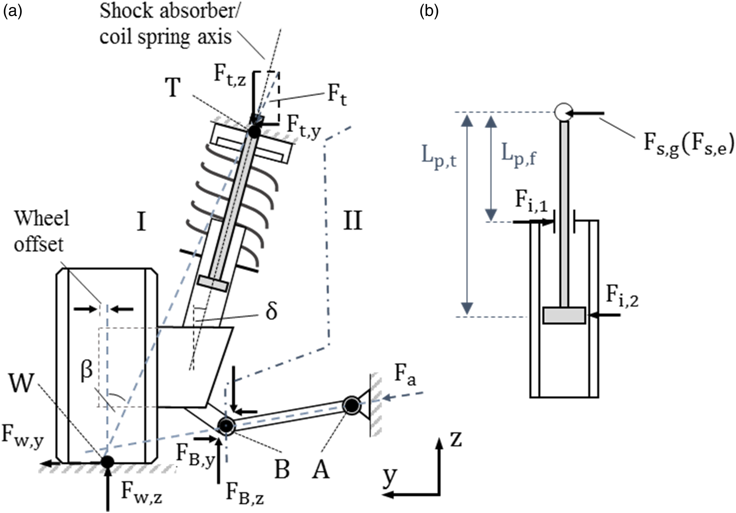
In consequence, the shock absorber eventually is subject to shear forces and bending (Deubel et al., 2022). According to (Lizarraga et al., 2008), the friction in the shock absorber may be greatly influenced by the shear force. (Kölsch, 1994) also highlights the significance of friction in the shock absorber of the spring-strut type suspension. Therefore, the suspension friction might largely consist, but not exclusively, of shock absorber friction. Thus, in the following, the kinetic situation of the shock absorber is investigated.
Assuming uniaxial spring properties without spring inclination in the first instance, which means that the spring is regarded as a force element purely acting along the excitation axis of the shock absorber, the shear force can be estimated from Figure 1(a). For that purpose, the system is subdivided by joint B (dash-dotted line). Equations (1), (2) and (3) and (4), (5) and (6) are obtained for the left (I) and right (II) subsystem, respectively.


For the above mentioned reasons, various shear forces can be assumed, corresponding to the forces at the TCP. Consequently, a varying amount of shock absorber friction and thus suspension friction will exist for various real driving conditions, such as cornering. The presented relationships and mechanisms aid to interpret some of the results presented in section 3.
Because of the wide application of the MacPherson suspension in the field of medium-sized and compact cars (Ersoy and Gies, 2017) and the presented shear force occurrence, this system was chosen for the suspension friction study reported in this paper. In this context, friction in the suspension is considered as all kinds of quasi-static hysteresis (measured at low speed), excluding the viscous friction of the shock absorber, which is caused by the hydraulic oil’s passage through the valves. Reversely, damping addresses mainly the latter part. For this study, the term friction signifies kinetic friction, while static friction was not explicitly regarded.
3. Suspension friction measurements
3.1. Instrumentation
The kinetic suspension friction was investigated on a full-vehicle test rig, the Suspension Motion Simulator (SMS), which is a dynamic kinematics and compliance (K&C) test rig from MTS Systems and which is visualized in Figure 2. The test rig is primarily used for quasi-static and dynamic K&C measurements to analyse the suspension characteristics depending on wheel deflection or on forces and moments acting at the TCP. For these types of full-vehicle tests, the vehicle’s chassis is fixed to the rig by clamping mechanisms. If the excitation is sufficiently small, like in this study, the deflection of the chassis is neglectable, allowing thus the sole investigation of suspension characteristics. The vehicle can be equipped either with its original tyre-rim set-up or the wheel can be replaced by a spindle couple (cf. Figure 3(b)), which eliminates the tyre’s elasticities. Generally, if the suspension characteristics are focused, it is beneficial to eliminate the tyre properties by using a spindle couple. A high-resolution optical stereo camera system is used to acquire displacement data of the wheel centre, the platform as well as of any other desired elements, for example, of suspension components. Six forces and moments are recorded at each of the two platforms according to the convention shown in Figure 2. Further information on the test rig can be found in (Deubel et al., 2020; Liu et al., 2019). Suspension motion simulator test rig at the Institute of Automobile Engineering. Suspension hysteresis (a) and coordinate convention at front left wheel (b).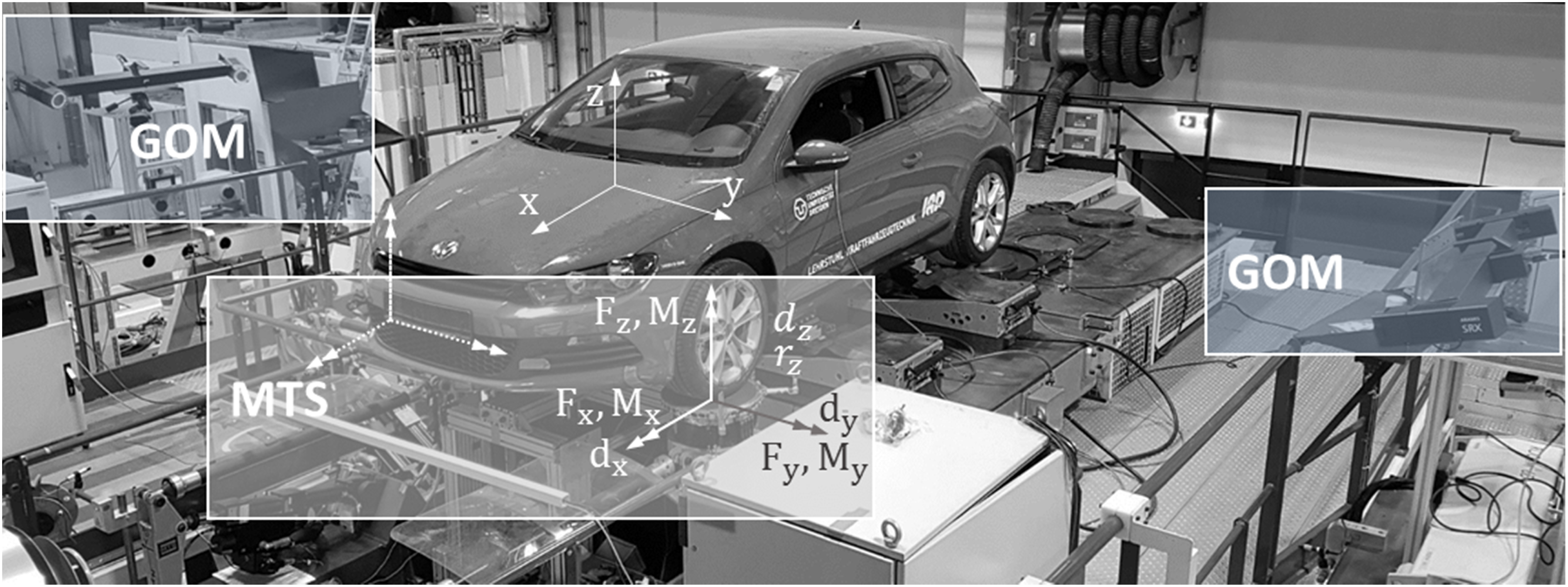
3.2. Test layout
All tests were performed with a low vertical amplitude input (3–5 mm wheel centre deflection), as the before-mentioned studies indicated the friction to be particularly adverse for small vertical wheel inputs. Furthermore, the conditions were kept a quasi-static manner (1 mm/s speed) to limit the shock absorber’s damping. The steering wheel was blocked. A spindle couple was used replacing the original wheels. All horizontal forces and moments, except for the desired parameter variation, were controlled to zero. The suspension was at the construction level (K0-level), if not stated otherwise, defined as the relative position of the wheels to the chassis because of the loading condition (a driver’s weight of 75 kg was used and the gas tank was at full level). All tests were performed in a so-called rolling condition of the suspension. This means that the left and the right wheel moved with a phase shift of 180° (while the chassis was fixed). This condition was chosen because it represents the suspension behaviour more realistic than a parallel condition, since an exact parallel wheel deflection is unlikely for road events.
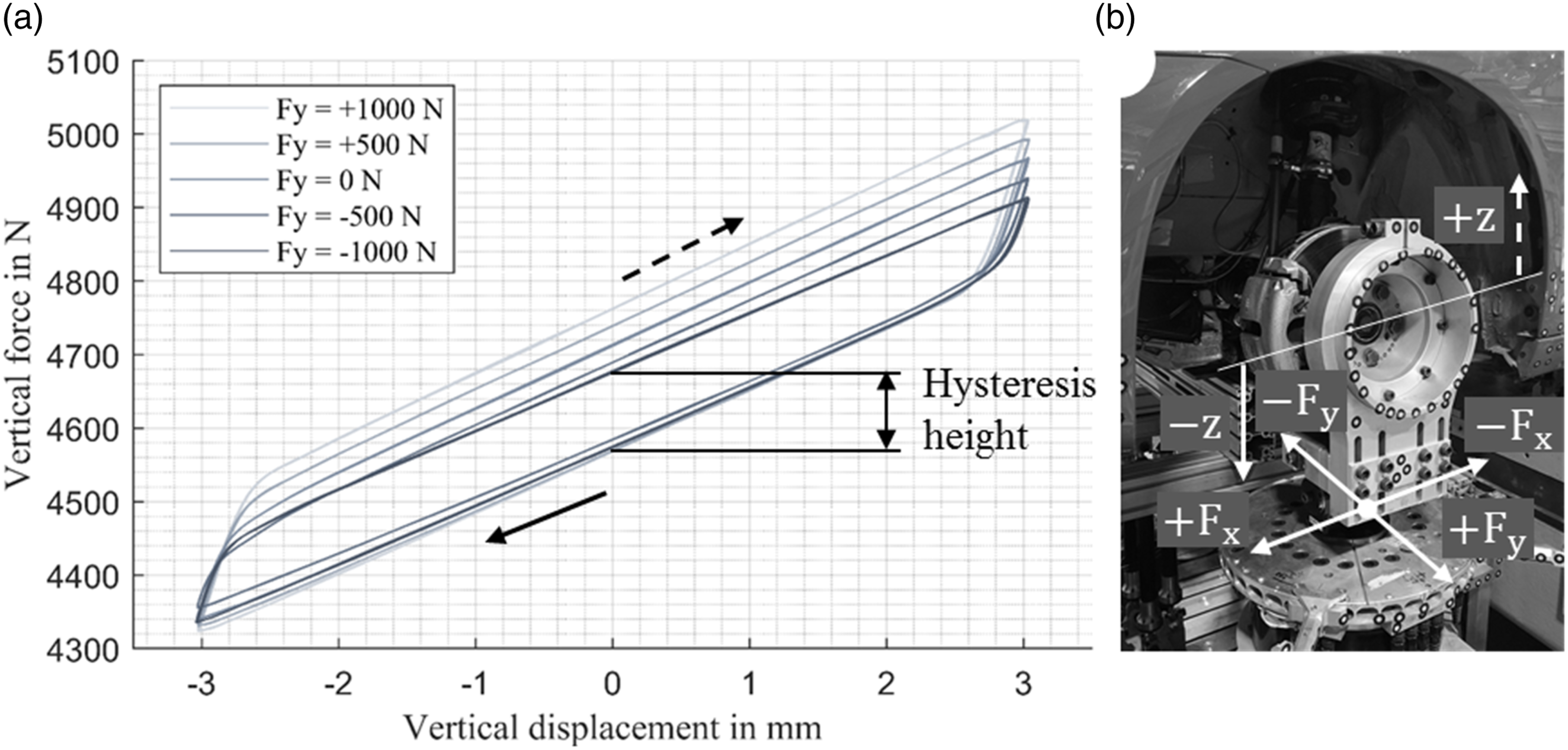
If spindle couples are used instead of tyres, the friction of the suspension can be calculated directly from the obtained force-displacement graphs of the wheel centre. In this context, suspension friction describes half the hysteresis height, see Figure 3(a). No differentiation was made regarding the direction of the movement (upwards or downwards).
The vehicle (VW Scirocco III, model year 2008) was tested under various influences, which were (1) TCP lateral force, (2) TCP longitudinal force, (3) wheel deflection and therefore TCP vertical force, (4) TCP steer moment, (5) excitation amplitude and (6) engine state in interrelation to TCP lateral force. The force and moment range was kept relatively small, representing low to medium driving manoeuvres with respect to the static wheel load of approx. 4600 N and therefore the force potential of the real tyres.
For the friction investigation, a strict protocol was followed to assure a high level of reproducibility and comparability. The tests, assigned to each of the before-mentioned influences, were performed strictly block-wise and as far as possible without breaks to avoid undesired ‘leaps’ in the characteristic curves. The ambient temperature was in a close range between 22.4°C and 25.7°C, except for the engine state variation. A specific warm-up procedure was performed previously aiming to eliminate undesired tension of the suspension components. As evident from Figure 4(a), the friction typically dropped after performing the warm-up, demonstrating its necessity. Effect of warm-up (a), standard deviation depending on performed cycles (b).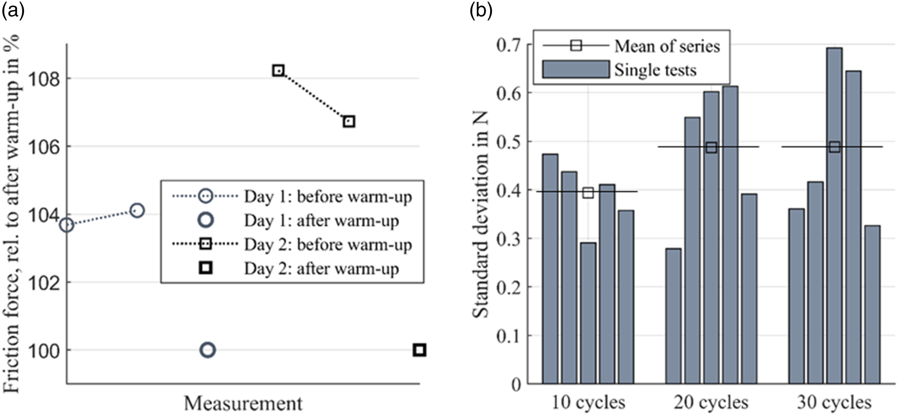
Contrary to K&C tests, performing only few cycles of each variation (typically up to 3), a higher number of cycles is performed to obtain a sufficient level of confidence of the measurements. Typically, the SD of the tests was between 0.5 and 1 N, as the results of a varying cycle count demonstrate (Figure 4(b)). Moreover, each parameter-defined test was performed multiple times consecutively and averaged afterwards as a standard. In case of a heightened SD during multiple repetitions, however, the respective repetitions were neglected. All signals were low-pass filtered before post-processing them.
For a test of higher cycle count (250 cycles), it becomes clear that the values are approx. normally distributed (Figure 5) which makes statistical methods applicable. In a few cases, if a clear outlier within a test was detected, it was possible to perform a specific statistical outlier test to clear the outlier, if so desired. Histogram of test with high cycle count.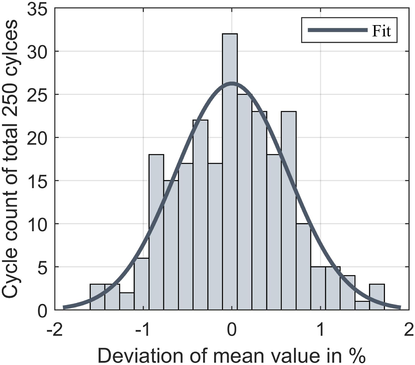
3.3. Suspension friction for various load cases
In Figure 6, Figure 7 and Figure 8, an overview of the performed parameter variations is given, each visualized for the front left (FL) and front right (FR) wheel. Each variation will be presented as follows. Results of variation: lateral force (a) and longitudinal force (b). Results of variation: wheel deflection (a) and steer moment (b). Results of variation: excitation amplitude (a) and engine state on/off (b).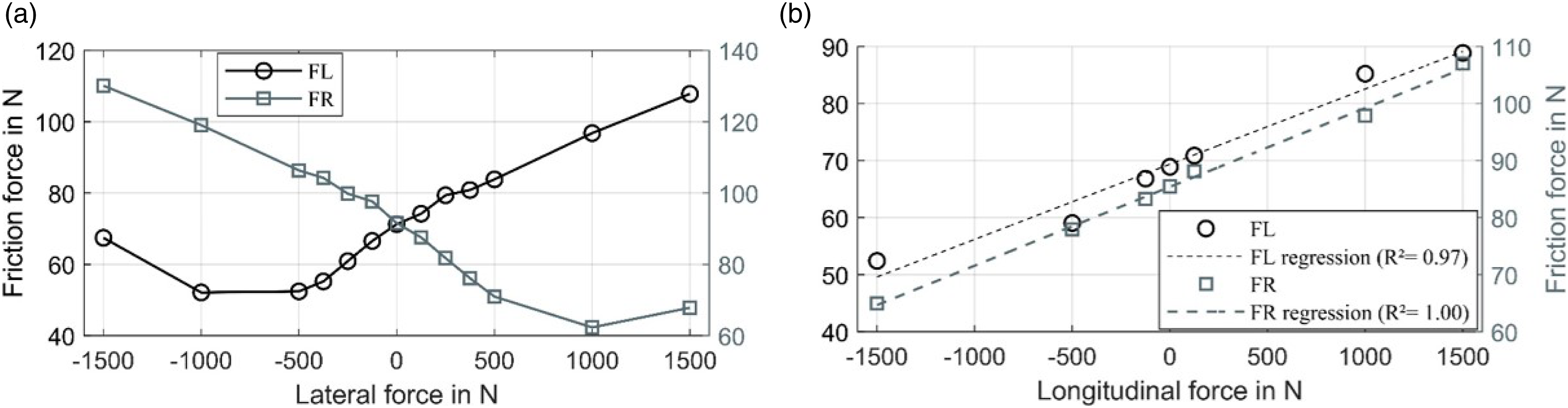
3.3.1. Lateral force
Figure 6(a) shows a simple lateral force variation. The friction varies strongly depending on the acting lateral force and becomes greater in comparison if the lateral force directs to the outside of the vehicle (that is in positive direction for FL, in negative direction for FR). In approximation, a partially linear relationship becomes evident, but a specific minimum is achieved at each side, which roughly exists between |500 N| and [1000 N| lateral force. Similar variations can be found when the wheel deflection and the respective wheel load were modified, as discussed later. Starting from that minimum, the friction increases continually and will continue to rise, even if higher forces than shown in the graphs will be applied. The reason for this is a similar linear relationship between the shock absorber shear load and the TCP lateral force, as will be explained in detail in another study. Considering the mechanisms of the suspension by examination of equations (7) to (10) indicates that the curve trends of Figure 6(a) are strongly related to the present shear force at the shock absorber.
Regarding the general friction level, those of FR is higher compared to FL for all variations. One reason is the higher wheel deflection of FR (≈+6 mm). Furthermore, not completely symmetric component properties (such as hysteretic behaviour) are typical as they are subject to high deviations in the production process. This is especially known for elastomer bushings (Ernst et al., 2020, 2021). Similarly, investigations of identical shock absorbers showed differences regarding their load-independent (base value) and load-dependent friction, too, see Figure 10(a).
3.3.2. Longitudinal force
As evident from Figure 6(b), there is an approx. linear relationship between the longitudinal force and friction, which is best seen at FR. The friction is therefore higher when the vehicle is accelerated or at constant speed than compared to breaking manoeuvres. The linearized friction increment (slope) is approx. 1.32 (1.38) N per 100 N
3.3.3. Wheel deflection/ load
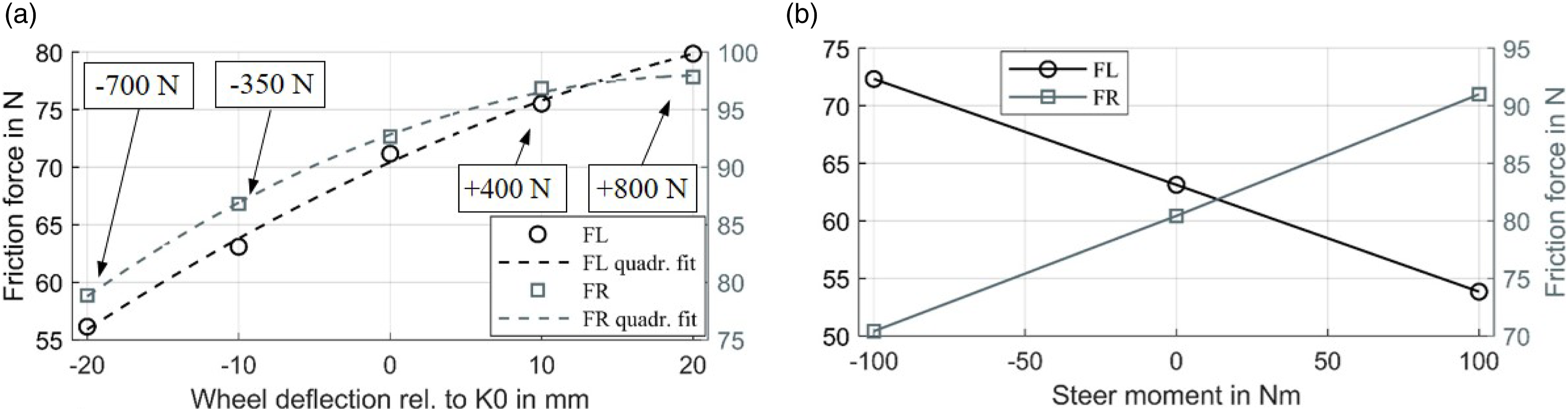
Figure 7(a) illustrates a wheel deflection variation without any additional horizontal forces or moments. Each step is characterized by an increase/ decrease of the wheel load correspondingly. As the applied second order fit suggests, the friction increases degressively with increasing wheel deflection. For comparison to the other variations, a linear slope is characterized by approx. 5.96 (4.76) N per 10 mm for FL (FR). It needs to be highlighted that this relationship is valid only for the performed parallel deflection change of both wheels, as approximately present during lane braking or acceleration. During cornering, the deflection and wheel load are related differently: the wheel load will be much higher during jounce or much lower during rebound. Therefore, the characteristic curve appearance might be completely different, since the shock absorber’s inner normal forces depend on the respective piston position (deflection) and the shear force (being approx. proportional to the wheel load), cf. Equations (11) and (12). Additionally, as the study of (Riedel, 2021) shows, the elastomer bushings’ hysteresis, which contribute to the suspension friction, depends on the preload, which likely increases with the load.
Analysing the forces at the shock absorber, the principal, uncompensated shear force increases approximately linearly with the increasing deflection. The compensating spring force increases only degressively as shown in Figure 9(a), owed to a general saturation of the spring’s lateral force. Furthermore, the increasing angle between the top mount and the shock absorber (from slightly negative to more positive) weakens the spring’s lateral force increase (Deubel et al., 2022). Therefore, theoretically the effective shear force increases progressively. Contrary, the piston normal force increase is weakened because of the decreasing free piston rod length, see Figure 9(b). On the other hand, the normal force at the piston rod, which increases rather linearly, should be dominant in terms of friction generation due to its much higher load. A study of a shock absorber under shear load by (Kruse and Zimmermann, 2002) confirms the predominance of the friction at the contact piston rod bearing. While the increasing friction by increasing deflection can be explained, this indicates that other mechanisms or suspension elements might affect the degressive suspension friction development. Forces perpendicular to the piston rod top (a) and resulting inner contact forces (b).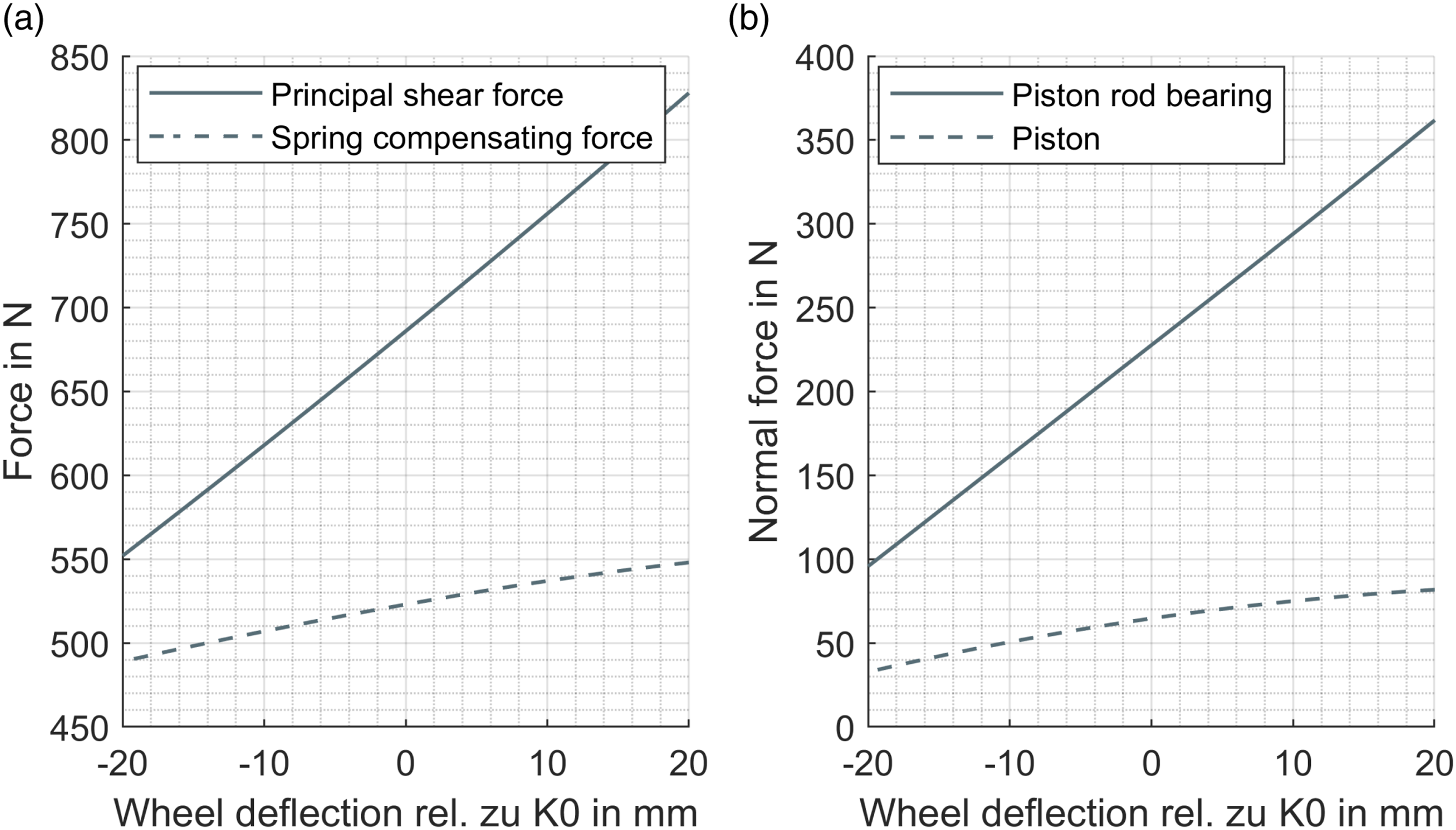
3.3.4. Steer moment
The variation of Figure 7(b) clearly shows a linear relationship between steer moment and friction. To create the steer moment at the rig, there will be contradictory motions of the two lateral cylinders of the test rig platform. Thus, effectively no lateral force was present. The mechanism leading to this relationship is not discussed in literature, but can potentially be indicated by the kinematic situation, as illustrated exemplarily for FL. For a positive steer moment, the wheel was turning as it would in left cornering, if the steering was not fixed. This is prevented by the tie rod (joint), because of the fixed steering wheel, which is located inwards and backwards relative to the TCP. Thus, the rotational motion of the wheel carrier is prevented, creating an outward oriented force at this joint. It is assumed that this force affects the bending or the present shear force of the shock absorber and thus the friction.
3.3.5. Excitation amplitude
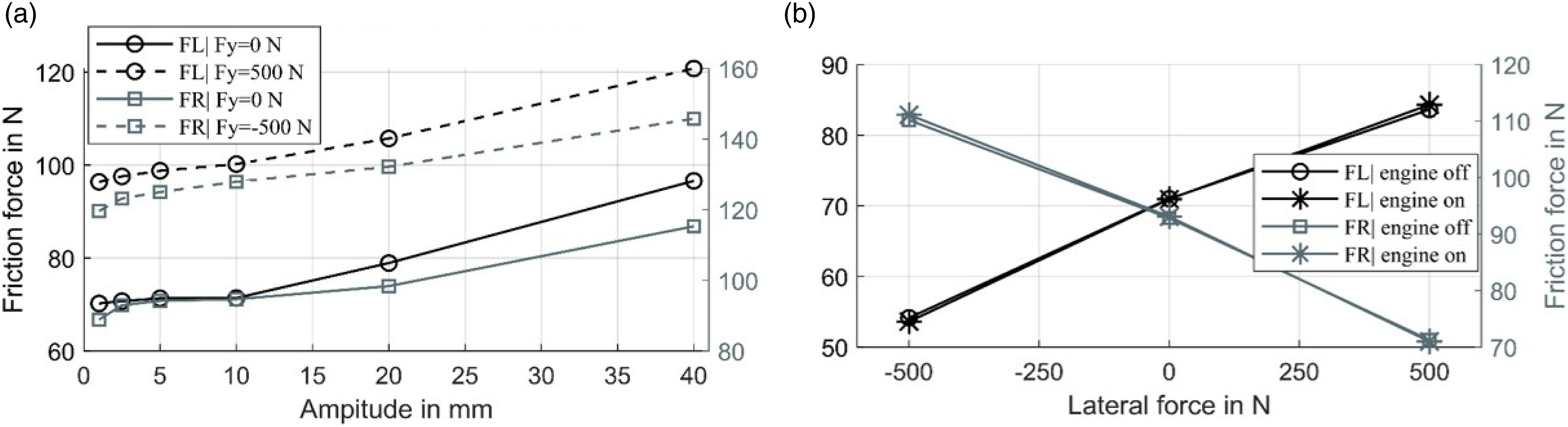
The amplitude dependence visualized in Figure 8(a) was performed with an additional lateral force, in order to investigate a load effect. For Shock absorber friction as a function of shear force (a) and amplitude (b).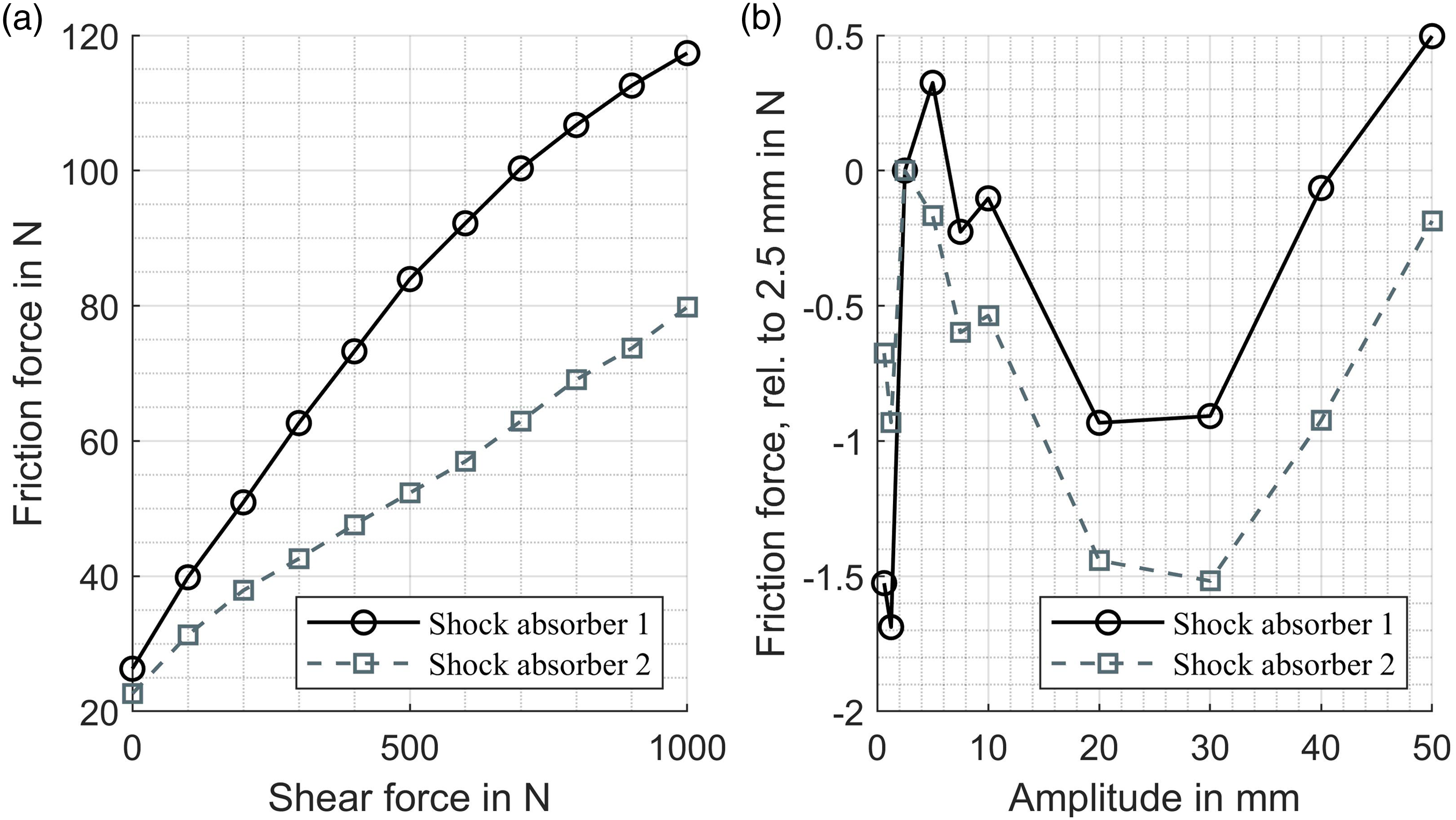
3.3.6. Engine state
The motivation of these tests was to assess the sensitivity of the suspension friction regarding the boundary condition of the engine state because it can be necessary to keep the engine running for certain tests, for example, if strong braking becomes necessary. The engine was either off or running at idle speed (approx. 800 rpm). While many studies deal with the effect of high frequencies on friction behaviour, fewer investigate lower frequencies (below 100 Hz). Despite many interrelations (e.g. material properties, amplitude and vibration direction) it can be said that even in the lower frequency range a friction reduction is theoretically possible, as the results of (Godfrey, 1967; Lenkiewicz, 1969; Zang et al., 2022) illustrate exemplarily. However, referring to Figure 8(b), the results clearly indicate no significant impact of the engine state on the suspension friction. This is independent of the friction level, which was manipulated by the lateral force.
While the focus was not to investigate the reducing effect of (high-frequency) vibration on friction in detail, it is not possible to provide a general statement on the friction interrelation. The engine design, the bearing concept of the engine, the vehicle structure, the engine speed and the applied torque might impact the vibration level at the suspension components and thus lead to a reduction of the friction level.
3.3.7. Combined lateral force-deflection
An extended variation of (1) (cf. Figure 6(a)), was performed and is shown in Figure 11. A characteristic friction minimum becomes evident, shifting to higher lateral forces (absolutely speaking) with increasing deflection. Generally, this is because of the increased shock absorber shear force as the wheel load increases (which will be discussed in depth in a pursuing study). Combined lateral force-deflection variation: front left (wheel) (FL) (a) and front right (wheel) (FR) (b).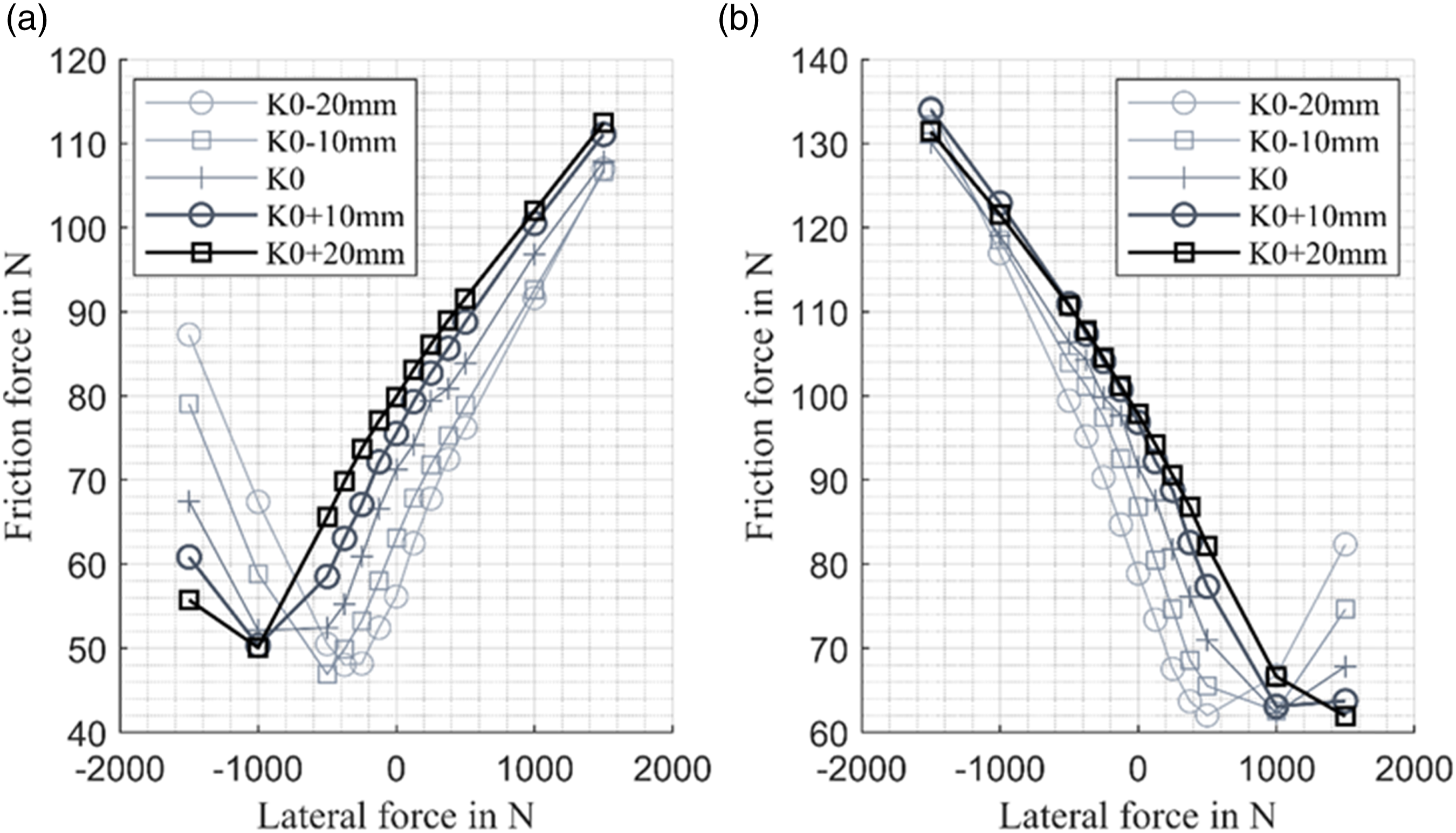
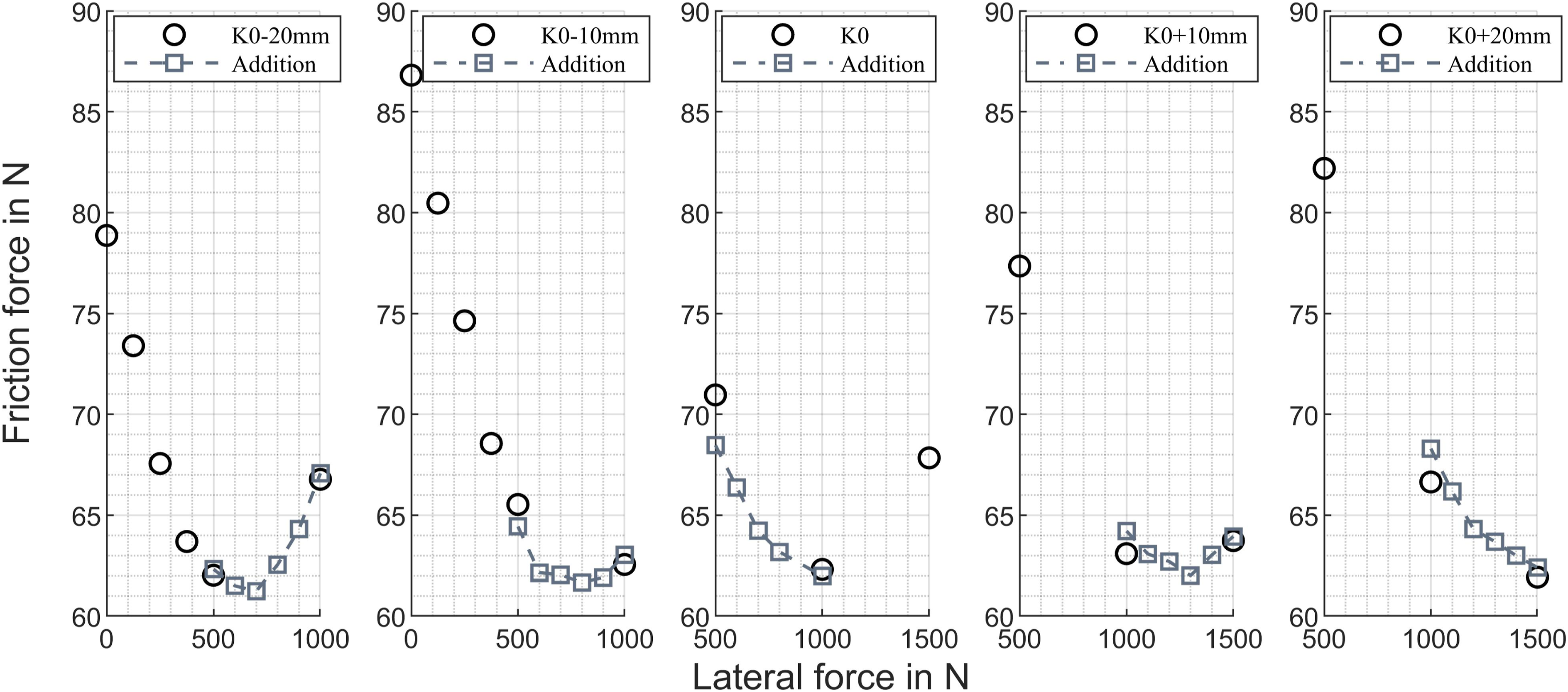
Unfortunately, the first test campaign was not able to detect the minimum in detail due to the rigid lateral force steps initially used. Subsequently, additional tests were performed in the range of the assumed minima with increased resolution and adapted lateral loads. As evident from Figure 12 and Figure 13, the minima could be located more clearly, especially at the construction level. It is worth mentioning that this second series, which was performed several days after the first test campaign, meets the initial friction levels very closely, signifying a high level of reproducibility. Moreover, the minima are always located between 45 and 50 N (60 and 65 N) for FL (FR), since for each suspension state the shear forces are cancelled at specific TCP force and moment sets, which in this case were dominated by the lateral force, leading to the minimum friction of the shock absorber. Additional measurements for combined lateral force-deflection variation (FL). Additional measurements for combined lateral force-deflection variation (FR).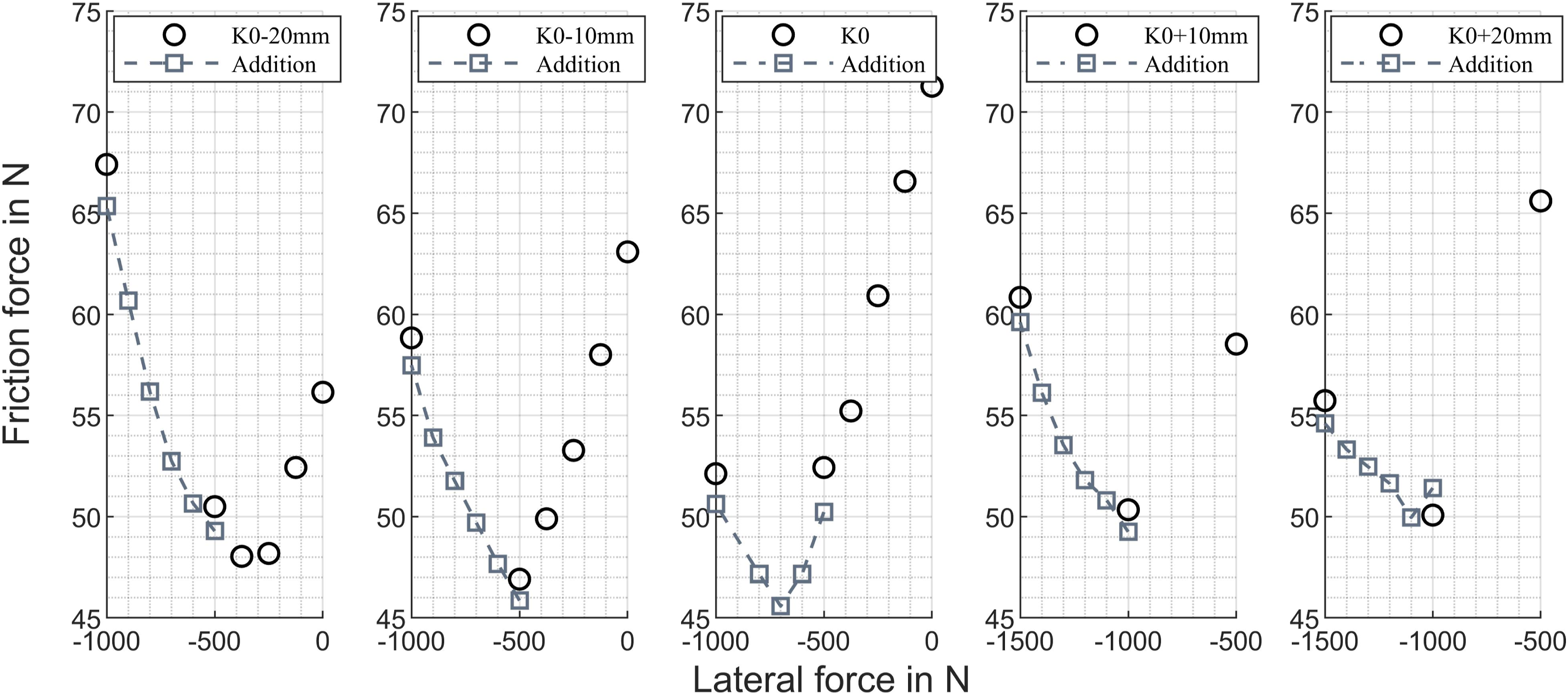
4. Conclusion
To begin to clarify to what extent the suspension friction consideration should be enlarged or modified in vertical dynamics analysis or in the automotive development process, this study presents an investigation on the friction of a MacPherson suspension. Friction is determined for various load cases and boundary conditions.
Regarding the boundary conditions for friction testing, a strong amplitude dependence is observed. It seems important to provide precise information for this condition in terms of comparability amongst studies. So far, the data base strongly suggests that the detected suspension friction is not affected significantly in the lower range (up to 10 mm). The engine state of the vehicle has no effect on the friction level for the tested front suspension, but should nevertheless be kept preferentially constant over a test series. While friction investigations as presented in this study can be conducted either on K&C test rigs or on simple vertical hydropulsers (which allow no control of the forces and moments in the horizontal TCP plane), it is strictly necessary to record the TCP loads as they impact the friction value, depending on the tested suspension system.
Regarding the load variation, the results indicate a strong effect on the detected friction, which can exceed the initial friction level (load-free in terms of additional horizontal forces and moments at the tyre contact patch) by up to 100% for the applied load range. For real, medium to extreme lateral or lane manoeuvres exceeding the presented load range and using the full potential of the tyre’s force transmission, the friction level will likely increase much further as the characteristic curve trends indicate. While some indicators were presented that explain the shown dependencies already, it is necessary to conduct further in-depth studies to identify the underlying effect mechanisms. In terms of future testing, it could also be interesting to implement combined load cases, such as combined cornering and braking, in order bring the results even closer to reality, while investigating the suspension friction evolution.
As identified from the kinetics of the suspension system, the lateral force mainly affects the friction, but the longitudinal and vertical TCP forces also constitute strong effects. Therefore, this study clearly demonstrates the strong volatility of the suspension friction for the suspension system tested herein. In the frame of ongoing research, further suspension systems should be investigated. In terms of suspension development, information on the participation of the various suspension elements on the suspension friction might aid to precisely design the suspension components. The various dependencies and interrelations of the friction should be subsequently implemented into an enhanced friction model in order to study the friction effect driving situation specifically. The final objective represents the identification of manoeuvres, for which an adaptively modelled friction influences the vehicle dynamics significantly, while focusing on safety and ride comfort.
Footnotes
Declaration of conflicting interests
The author(s) declared no potential conflicts of interest with respect to the research, authorship and/or publication of this article.
Funding
The author(s) received no financial support for the research, authorship and/or publication of this article.