
Abstract
Systems engineers often use model-based simulations to evaluate design concepts before building physical prototypes and running live experiments. However, their simulations typically lack infrastructure representing human behavior (e.g., cognitive tasks) and performance measures (e.g., workload). While human factors practitioners have developed simulation approaches that include such infrastructure, they typically employ languages, tools, and techniques that engineering teams cannot easily adopt given real-world budget and schedule constraints. To address this challenge, we propose a novel, lightweight approach to human-integrated system simulation analysis. Our approach enables the analyst to take a preexisting system model, add minimal human-model infrastructure, and run whole-system simulations that produce operator-workload and task-duration estimates, all using a common engineering language and tool, SysML and Cameo Systems Modeler, and any preexisting behavioral modeling technique. We demonstrate the approach using a simple, preexisting model of a fictitious space-telescope system.
Keywords
Introduction
Engineers often use system models—symbolic representations of a target system’s structure, behavior, and performance measures—to simulate and improve design concepts before building physical prototypes and running live experiments. Common examples include “what-if” analyses, where model parameters are adjusted to simulate the effects of a design modification; trade studies, where competing designs are simulated to compare performance measures; and forecasting, where model parameters are assigned probability distributions, and simulations are run to predict long-term outcomes.
The model infrastructure behind these simulation analyses typically represents designed components (e.g., actuators, algorithms) and technology-performance measures (e.g., data throughput, component-failure rates). However, what’s often missing is model infrastructure representing human operators and human-performance measures (e.g., workload, task duration). Such infrastructure is needed to run complete, human-integrated system simulation analyses, such as to estimate how increasing data throughput affects operator workload, or to predict long-term component-failure rates given variable operator-task behaviors.
Human factors researchers have developed a variety of model-based approaches that can support these kinds of human-integrated system simulation analyses. However, extant approaches employ languages, tools, and techniques that engineering teams do not typically use and cannot easily adopt on real-world projects under real-world conditions (i.e., “in the wild”).
For example, Watson et al. (2017) developed an approach for performing model-based trade studies that compare different automation designs with respect to operator workload. Their approach involves inferring a human-system interaction model from a preexisting system model, manually encoding the human-system interaction model in a task-network syntax (Mitchell, 2000), and running workload analyses in a specialized simulation tool. This kind of approach can inform design improvements, but it requires engineering teams to create, validate, and maintain simulation models that are encoded in dissimilar languages and developed/executed via noninteroperable tools. Such additional work and overhead can be unacceptable given tight budgets and schedules.
Other researchers have developed approaches that use the same languages and tools as engineers, but unfamiliar behavioral modeling techniques. For example, LaMonica et al. (2022) developed a human-integrated system analysis approach using Systems Modeling Language (SysML) and Cameo Systems Modeler—a widely utilized engineering language and tool, respectively. Their approach employs two custom SysML constructs: one that the analyst instantiates to model high-level human-machine collaboration, and another that the analyst instantiates to represent how each collaborating agent—either a human or a machine—executes its allocated activities via information-processing loops. The analyst can then add duration estimates to the model and run simulations. This kind of approach can also inform design improvements, but it imposes custom behavioral modeling techniques that engineers do not use and a prescribed SysML construct (i.e., activity diagrams with swim-lanes) that may violate preexisting conventions. These are barriers to adoption, especially for engineering teams with language rules that cannot be changed or system models that cannot be refactored.
To support human-integrated simulation analyses “in the wild,” where preexisting system models and conventions shape practicability, analysts need an approach that leverages widely applied human-performance measures, employs a language and tool that engineers already use, and can be integrated with any preexisting system model—including associated language constructs—without refactoring. Using such an approach, an analyst or team should be able to take a preexisting system model that does not represent humans as part of the system, add minimal human-model infrastructure without breaking the preexisting model, and run whole-system simulations that produce at least one human-performance measure alongside technology-performance measures, if any.
This paper introduces one such approach.
Proposed Approach
Our approach employs SysML and Cameo Systems Modeler tool, a widely used language and tool, respectively, in systems engineering, alongside operator-task duration estimation, and operator-Visual/Auditory/Cognitive/Psychomotor (VACP) workload estimation (Mitchell, 2000), widely used performance measures in human factors. Starting with a preexisting system model, the analyst executes our approach in five steps: (a) Represent the human operator and operator tasks as parts of the system; (b) add model infrastructure that enables VACP workload estimation; (c) integrate operator-task behavior within a preexisting behavior model; (d) parameterize the model with VACP values and task-duration estimates; and (e) run simulations and process results.
The following subsections explain these steps. For brevity, we aim to provide minimally sufficient detail for an analyst or team that already understands SysML, Cameo Systems Modeler, VACP workload estimation, and task modeling. To supplement, we reference tutorial materials throughout this section and provide a case-study example in the next section.
Representing the Human Operator and Operator Tasks as Parts of the System
Starting with a preexisting system model, the first step of our approach is adding model infrastructure to represent a human operator and tasks. For this, the analyst creates a new SysML Block to represent the human operator (referred to as the Operator Block), then adds to the system model a Part Property typed by this Block (referred to as the Operator Part).
Next, the analyst creates one SysML Block for every atomic operator task (referred to as Task Blocks). If atomic operator tasks are known, then the analyst creates one Task Block for each such task. Otherwise, the analyst should estimate how many Task Blocks will be needed (Task Blocks can be added or deleted later). Then the analyst adds Part Properties typed by these Task Blocks (referred to as Task Parts) to the Operator Part (one Task Part for each Task Block). These elements will be modified next to enable workload estimation.
Adding Model Infrastructure that Enables VACP Workload Estimation
Our approach to VACP workload estimation is inspired by Moberley (2020), who uses a SysML construct called a Rollup Pattern to compute a system’s dynamic power utilization. To similar effect, we employ the WorkloadRollupPattern (Figure 1), which we created to compute a human operator’s dynamic workload-resource utilization. To use this pattern, the analyst creates it within the system model and applies it to the Operator Part via the Rollup Pattern Wizard with the “Apply Recursively,” “Set Subsetted Properties,” and “Create Value Properties and Redefine” settings enabled (see No Magic, Inc., n.d. for more information about the Rollup Pattern Wizard). This provides the Operator and Task Blocks (and thus the Operator and Task Parts) with their own unique copies of all elements in the WorkloadRollupPattern pattern, explained next.
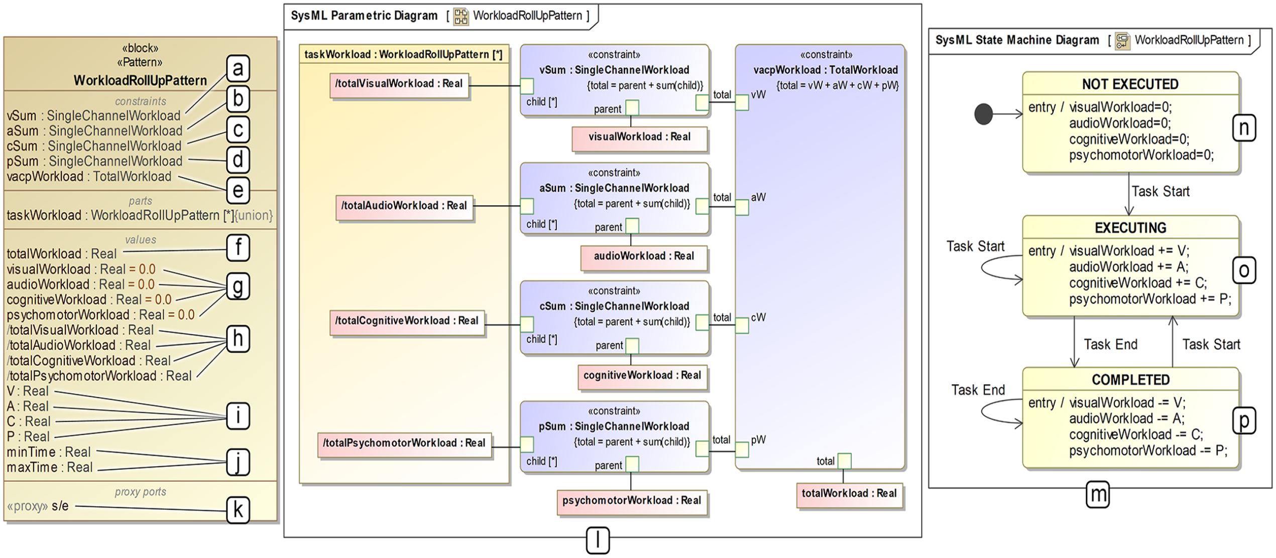
WorkloadRollupPattern. (a–e) Constraint properties that calculate visual, audio, cognitive, psychomotor, and VACP workloads during simulation analyses. (f) The value property that stores instantaneous VACP workload during simulation analyses. (g) Value properties that store instantaneous visual, audio, cognitive, and psychomotor workloads during simulation analyses. (h) Auxiliary value properties that serve as inputs to the constraint properties. (i) Value properties that the analyst uses to specify visual, audio, cognitive, and psychomotor workloads within Task Blocks. (j) Value properties that the analyst uses to specify minimum and maximum task-execution durations within Task Blocks. (k) The proxy port on which Task Blocks receive Task Start and Task End Signals during simulation analyses. (l) The Parametric Diagram that executes workload calculations during simulation analyses. (m) The State Machine that adds and subtracts analyst-specified V, A, C, and P values for target Task Blocks in response to Task Start and Task End signals during simulation analyses. (n) The NOT EXECUTED Task Block state (i.e., initial state), which sets channel-specific instantaneous workload values to zero. (o) The EXECUTING Task Block state, which adds analyst-specified V, A, C, and P values to corresponding, channel-specific instantaneous workload values in response to a Task Start signal. (p) The COMPLETED Task Block state, which subtracts analyst-specified V, A, C, and P values from corresponding, channel-specific instantaneous workload values in response to a Task End signal.
The WorkloadRollupPattern includes 15 SysML Value Properties. Six only apply to each Task Block: V, A, C, and P (Figure 1i), which capture workload resource required by the represented operator task, and minTime and maxTime (Figure 1j), which capture minimum and maximum task-duration estimates for the represented operator task. The analyst will assign values to these elements in step-4. Four SysML Value Properties apply to Task Blocks and the Operator Block. For each Task Block, visualWorkload, audioWorkload, cognitiveWorkload, and psychomotorWorkload (Figure 1g) capture instantaneous workload resources in use for the represented operator task. For the Operator Block, these four values capture channel-specific instantaneous workload resources in use by the operator. One SysML Value Property, totalWorkload (Figure 1f), only applies to the Operator Block, and it captures instantaneous VACP workload (i.e., sum of resources in use). The four remaining SysML Value Properties (Figure 1h) serve as inputs to the WorkloadRollupPattern’s five SysML Constraint Properties (Figure 1a–e), which calculate workload resources in use as defined by the depicted SysML Parametric Diagram (Figure 1l).
The WorkloadRollupPattern also includes a SysML State Machine (Figure 1m) and Proxy Port (Figure 1k). These elements only apply to Task Blocks. When a simulation begins, each Task Block is in the NOT EXECUTED state (Figure 1n), and its resource-in-use values (visualWork, audioWorkload, cognitiveWorkload, and psychomotorWorkload) are set to 0. When the represented operator task starts, the Task Block enters the EXECUTING state (Figure 1o), and its resource-in-use values increase by its analyst-specified V, A, C, and P values. When the represented operator task ends, the Task Block enters the COMPLETED state (Figure 1p), and its resource-in-use values decrease by the same V, A, C, and P values. These operations are supported by a SysML Internal Block Diagram for the Operator Block (Figure 2a). Within that diagram, the analyst creates one SysML Proxy Port for each Task Part (referred to as a Task Port) and connects it to a corresponding Task Part’s “^s/e” Proxy Port, as exemplified in Figure 2a. These connections carry two SysML Signals, Task Start (Figure 2b) and Task End (Figure 2c), which trigger Task Block state transitions during a simulation. The analyst can add these SysML Signals anywhere within the system model before moving to step-3.
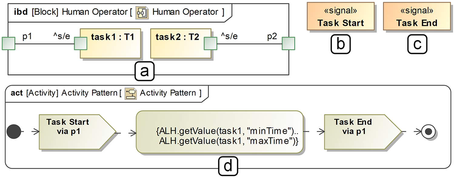
Additional model infrastructure required by our approach: (a) an example SySML Internal Block Diagram for the Operator Block, (b) the Task Start Signal, (c) the Task End Signal, (d) the SysML Activity Diagram pattern instantiated for an example Task Part/Task Port in (a).
Integrating Operator-Task Behavior within a Preexisting System-Behavior Model
To avoid imposing on a preexisting behavioral model, we use a generic SysML Activity Diagram pattern (Figure 2d), which can be invoked from any other behavioral SysML construct, to define atomic operator tasks. To employ our approach, the analyst creates a new SysML Activity for each atomic operator task and instantiates the SysML Activity Diagram pattern depicted in Figure 2d. To implement this pattern, the analyst references target Task Ports within the SysML Send Signal Actions and Task Parts within the SysML Duration Constraint expressions, as exemplified in Figure 2. The analyst can then insert invocations of the instantiated patterns within a preexisting, higher-level behavioral model of any form (e.g., SysML Sequence Diagram, SysML Activity Diagram).
Parameterizing the Model with VACP Values and Task-Duration Estimates
To parameterize the model, the analyst specifies V, A, C, P, minTime, and maxTime values for each atomic operator task. The analyst (or team of analysts, including a qualified human factors practitioner) should base these values on literature and a user interface concept, design, or implementation, as one would when performing VACP workload estimation using a different tool. Once determined, the analyst encodes these values directly within target Task Blocks (e.g., “T1” for the Task Part named “task1” in Figure 2a).
Running Simulations and Processing Results
After parameterizing the model, the analyst can run whole-system simulations that estimate VACP workload, generate graphs, and store results for further processing. To do this, the analyst should construct a SysML Simulation Configuration and, depending on the target analyses, optionally add infrastructure for deriving other metrics (e.g., time elapsed during which operator workload exceeds an acceptable threshold). These considerations are context-dependent, and a detailed discussion is outside the scope of this work. However, we direct readers to Pavalkis (2022) for a tutorial on SysML Simulation Configuration, and we demonstrate an analysis with additional metrics in the next section.
Case Study
To demonstrate our approach, we leveraged a sample model, SpaceStation.mdzip, which is packaged with Cameo Systems Modeler. This model specifies a fictitious space-telescope system composed of one telescope and one space station. The telescope generates photos and streams them to the space station at a specified rate (e.g., 2/hr), while the space station colorizes photos as they come in. Such a system may include a human operator, operator tasks, and a user interface for executing those tasks, but no such elements are in the model. Thus, we incorporated a human operator and operator tasks, designed a graphical user interface (GUI) concept to support operator tasks, and ran simulation analyses comparing two system designs with respect to operator workload.
Adding to the Preexisting System Model
The preexisting system model includes one top-level SysML Block, Space System, which has two unnamed SysML Part Properties representing the telescope and space station (typed by SysML Blocks named Space Telescope and Space Station). We added to this model a SysML Block representing a human operator (named Human Operator) and 15 SysML Blocks representing atomic operator tasks (named T1–T15), estimating that 15 would be sufficient to model a simple human-system interaction procedure. We then added the Operator Part to the Space System Block, added the Task Parts to the Operator Part, instantiated the SysML Internal Block Diagram (as exemplified in Figure 2a), applied the WorkloadRollupPattern to the Operator Part, added the Task Start and Task End Signals, and incorporated human-system interaction within the preexisting behavioral model (Figure 3).
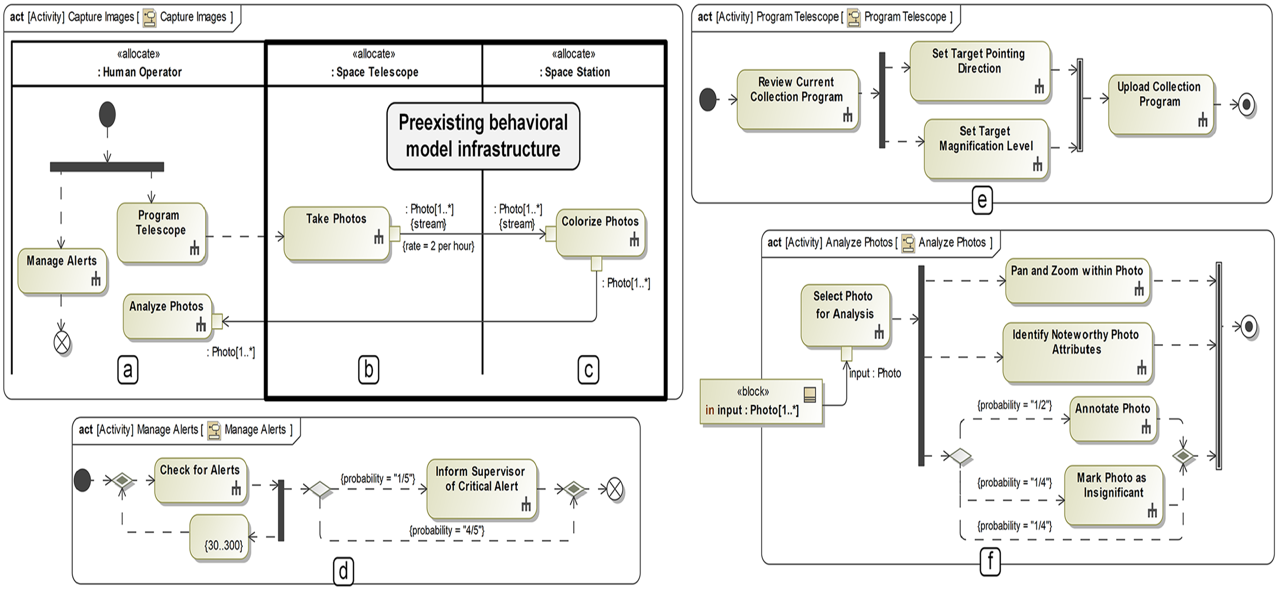
(a) Operator swim-lane and SysML call behavior actions added to integrate operator behavior with the preexisting behavioral model, (b–c) preexisting behavioral-model infrastructure, (d–f) operator task models invoked by the SysML Call Behavior Actions in (a).
In the sample model, the Space System’s behavior is encoded as a SysML Activity Diagram with swim-lanes for the telescope (Figure 3b) and space station (Figure 3c), each of which have one Call Behavior Action (lower-level behaviors not depicted). To integrate operator behavior in a way that works with this preexisting model, we added a swim-lane for the Operator Part and, within that swim-lane, encoded a notional human-system interaction procedure using SysML Call Behavior Actions (Figure 3a). In this procedure, the operator begins by programing the space telescope’s photo-collection behavior while managing alerts in parallel. Then, as the telescope takes photos and the space station colorizes them, the operator continues managing alerts while analyzing incoming photos in parallel.
We constructed SysML Activity diagrams for each SysML Activity invoked in this procedure (Figure 3e–f) and instantiated our SysML Activity Diagram pattern (Figure 2d) for the 11 atomic tasks therein (instantiated patterns not depicted). The notional GUI (Figure 4) enabled us to parameterize the Task Parts with minTime, maxTime, V, A, C, and P values. To identify these values, we imagined which section(s) of the GUI an operator would use for each task, roughly estimated minimum and maximum task durations for a typical operator, and identified task types, and corresponding VACP workload values from Mitchell (2000) (as depicted in Figure 4). We then encoded these parameters within target SysML Value Properties of the target Task Blocks (not depicted).
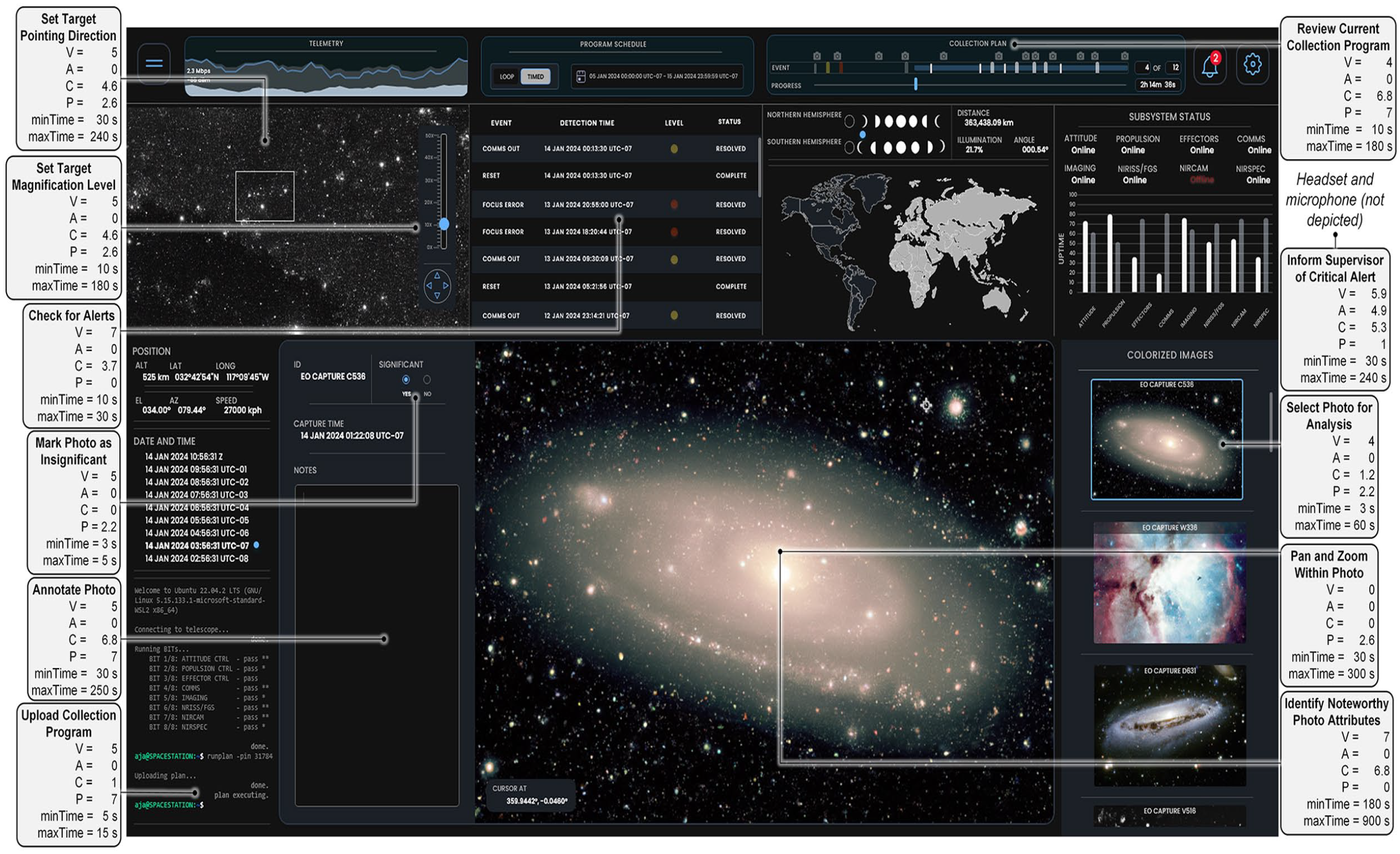
Mockup of a fictitious GUI designed to inform V, A, C, P, minTime, and maxTime values. Rounded-edge rectangles identify operator tasks and parameter values. Lines connect each task to the part of the GUI (or other interface component) that supports the task.
Running Simulations Analyses and Processing Results
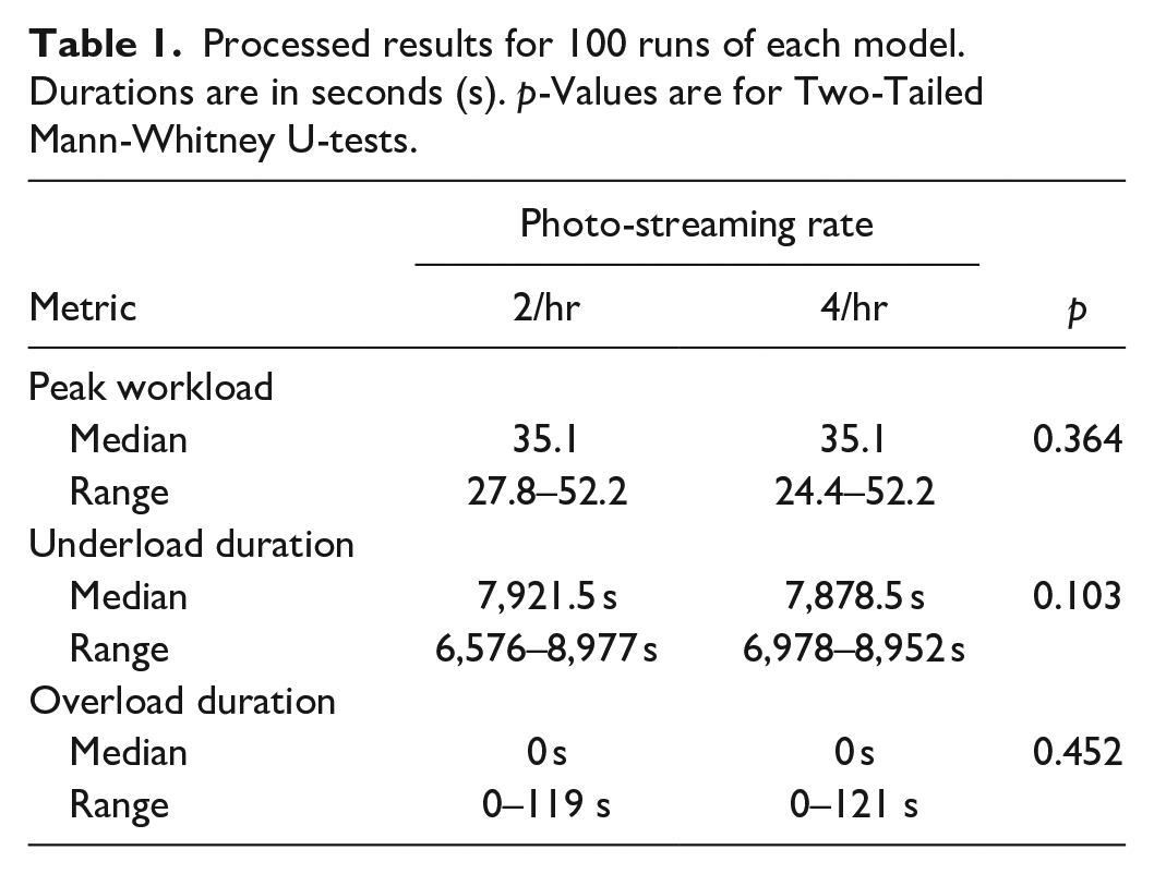
As an illustrative analysis, we compared system designs having different photo-streaming rates—2/hr and 4/hr—with respect to operator workload. This involved (a) constructing a SysML Simulation Configuration to run 100 simulations executing for 10,800 s, or 3 hr; (b) encoding model infrastructure (not depicted) to record the additional metrics of interest identified below; and (c) executing the SysML Simulation Configuration for two versions of the model reflecting the two photo-streaming rates. For each three-hour simulation, additional metrics of interest included peak workload (i.e., the highest operator workload recorded), overload duration (i.e., seconds elapsed during which vacpWorkload > 40), and underload duration (i.e., seconds elapsed during vacpWorkload = 0).
Results (Table 1) indicate that operator overload can occur in this system, but underload is likely a problem—roughly 70% of the operator’s time could be spent doing nothing. The photo-streaming rate does not affect overload or underload in either direction, so other design interventions should be explored to engage the operator’s attention during idle periods.
Processed results for 100 runs of each model. Durations are in seconds (s). p-Values are for Two-Tailed Mann-Whitney U-tests.
Discussion
This paper has introduced a novel, lightweight approach to human-integrated system simulation analyses using SysML, Cameo Systems Modeler, task-duration estimation, and VACP workload estimation. Through a case study, we demonstrated one way of applying the approach to a preexisting system model that excludes human operators. Our approach aims to give real-world engineering teams, who operate under tight budgets and schedules, a practicable way of adding human-performance measures to their baseline simulation analyses. We do not aim to replicate exactly what human factors practitioners can do with bespoke languages and tools (and thus match theoretical validity); however, such replication is possible with SysML and Cameo Systems Modeler. Assuming the current approach is sufficiently lightweight for existing engineering teams, future work should explore matching the capabilities of human factors languages and tools, such as by replicating task-network semantics, workload-management strategies, and advanced workload estimation implemented by Mitchell (2000). To further improve feasibility, future work should also explore ways of leveraging human-machine interface models, which are needed to implement advanced workload estimation, and automatically generating required model infrastructure, which a Cameo Systems Modeler plugin could support. Finally, the spirit of our approach, which prioritizes simplicity and integration with preexisting models, should be applied to other methods, such as human-reliability analysis, to expand the set of human-integrated system simulation capabilities that are practicable “in the wild.”
Footnotes
Declaration of Conflicting Interests
The author(s) declared no potential conflicts of interest with respect to the research, authorship, and/or publication of this article.
Funding
The author(s) disclosed receipt of the following financial support for the research, authorship, and/or publication of this article: Portions of this work were supported by Dr. Jeffrey G. Morrison, program officer ONR Division 341, under contract number N00014-22-C-2008, public release approval DCN: 0543-1810-24.