
Abstract
A piezoelectric vibration-based energy harvester (PVEH) consists of an electromechanical structure and an electric circuit, influencing each other. The finite element method (FEM) allows for the simulation of arbitrarily shaped and nonlinear electromechanical structures, while an electronic circuit simulator (ECS) can be applied to simulate arbitrary electric circuits. We propose a novel implicit FEM-ECS coupling method, which combines the advantages of the FEM and the flexibility of an ECS. The Newton-Raphson method is applied to achieve rapid convergence at the interface between the FEM and ECS simulations, so that arbitrary PVEHs can be efficiently analyzed. The new implicit FEM-ECS coupling is validated against explicitly and monolithically coupled FEM-ECS simulations of PVEHs from literature. Moreover, an application example consisting of a nonlinear electromechanical structure and a self-powered SSHI circuit is considered and a shock-like base excitation is applied. The examples demonstrate the practical applicability of the novel coupling method for realistic simulations of PVEHs.
Keywords
1. Introduction
A piezoelectric vibration-based energy harvester (PVEH) is a combined device consisting of an electromechanical structure in conjunction with an electric circuit. Such a device converts ambient vibration energy into electric energy to drive low-power electronics (Erturk and Inman, 2011b). PVEHs provide clean energy and are an alternative to conventional non-environmentally friendly power sources such as batteries (Safaei et al., 2019). The piezoelectric effect, which describes an interaction between mechanical and electrical quantities, is exploited as the energy conversion mechanism of PVEHs (Rupitsch, 2018).
The most common electromechanical transducer in vibration energy harvesting is a cantilever beam (Safaei et al., 2019). Linear beam-type PVEHs for example in unimorph (a single piezoelectric layer bonded to a substrate layer) or bimorph (a single substrate layer with two symmetric piezoelectric layers bonded on each side) configuration are very efficient when excited at resonance and often a tip mass is added to further improve the energy output (Safaei et al., 2019). However, if the mechanical excitation of linear PVEHs does not exactly match the resonance frequency, the power output drops dramatically (Gammaitoni et al., 2009; Liang et al., 2021). To overcome this issue of the narrow bandwidth of linear PVEHs, nonlinearities are intentionally introduced resulting in a significant extension of the bandwidth (Erturk and Inman, 2011a; Leadenham and Erturk, 2015; Zhou et al., 2016). In addition to these intentionally introduced nonlinearities the electromechanical structure itself typically shows nonlinear constitutive and dissipative behavior for moderate to large levels of mechanical excitation (Leadenham and Erturk, 2020; Stanton et al., 2010, 2012). Consequently, nonlinearities of the electromechanical structure are an important characteristic of PVEHs and must be considered in their design and modeling.
An electric circuit is used to extract the energy from the electromechanical structure. During oscillation, the electromechanical structure naturally generates alternating electric signals (Erturk and Inman, 2011b). However, charging an electric storage component requires a DC signal, meaning that the electric circuit must perform an AC-to-DC conversion and is hence forced to be nonlinear. Due to the direct and indirect piezoelectric effect the electric circuit and the electromechanical structure mutually influence each other. Accordingly, an accurate simulation of a PVEH requires the modeling of both the nonlinear electromechanical structure and the nonlinear electric circuit.
Analytical models of PVEHs are generally limited to simple geometries and circuits, and offer little flexibility with respect to changes in boundary conditions (Erturk and Inman, 2008). As a consequence, numerical methods have evolved and are generally more flexible than analytical models, but their disadvantage is the high computational cost. In Elvin and Elvin (2009b) and Yang and Tang (2009) an electronic circuit simulator (ECS), which allows for the simulation of arbitrary electric circuits, is applied for system simulations of complete PVEHs. The mechanical degrees of freedom are decoupled via modal analysis, which limits the approaches to linear electromechanical structures. Furthermore, equivalent electric circuit models of PVEHs considering dissipative and stiffness nonlinearities are introduced in Silva et al. (2018) and Elvin (2014).
Often, the finite element method (FEM) is applied for the simulation of PVEHs and allows to solve the full set of 3D piezoelectric equations (Hegendörfer et al., 2022a; Yamamoto et al., 2021). FEM simulations of electromechanical structures are coupled with linear passive electric circuit elements in Wang and Ostergaard (1999), Zhu et al. (2009), De Marqui Junior et al. (2009), Abdelkefi et al. (2014), Akbar and Curiel-Sosa (2019), and Ishihara et al. (2021). However, practical electric circuits for PVEHs necessarily require nonlinear components. In Wu and Shu (2015) the equivalent steady state impedances of the standard and synchronized switch harvesting on inductor (SSHI) circuit are derived and directly included in an FEM software using available passive electric circuit elements.
Recently, in Hegendörfer et al. (2022b) a system simulation method that allows finite element simulations of nonlinear electromechanical structures coupled to nonlinear electric circuits is introduced. The FEM solves the complete set of piezoelectric equations while the electric circuit is considered via the boundary conditions. Since no ECS is used, realistic electric circuit components cannot be considered.
In summary, the FEM offers powerful simulation capabilities for the electromechanical structure, but provides only limited capabilities for the consideration of electric circuits. Conversely, an ECS can simulate arbitrary electric circuits, but offers only limited possibilities for simulating electromechanical structures. Therefore, there are efforts to combine the two simulation methods to overcome their inherent limitations.
In Elvin and Elvin (2009a) an explicit coupling between a purely mechanical FEM simulation and an ECS simulation for the electric circuit is presented. In the approach, the electric behavior of the electromechanical structure of a PVEH is simplified to a lumped capacitance, which may not be appropriate especially for strongly coupled electromechanical structures (Gedeon and Rupitsch, 2018). An explicit coupling means, that no iterations between the FEM and ECS simulations are conducted and equilibrium between the two simulation domains is not ensured. Consequently, small time step sizes are necessary to obtain accurate results, which leads to high computational costs.
Monolithic FEM-ECS coupling approaches reported in the literature (Aftab et al., 2012; Gedeon and Rupitsch, 2018; Xiang et al., 2018) exploit a multiphysics simulation environment, which includes an ECS. The algebraic equations stemming from an FEM discretization of the electromechanical structure are reduced and integrated along with the electric circuit model into one system using a multiphysics simulation environment. Subsequently, the resulting system can be solved consistently in the multiphysics simulation environment. This modeling strategy can take into account arbitrary electric circuits but nonlinearities of the electromechanical structure or changing mechanical boundary conditions cannot be considered.
Overall, the FEM-ECS coupling methods reported in the literature are limited to linear electromechanical structures or the electromechanical structure is simplified and the coupling between the FEM and the ECS simulation is not very efficient. The main advantage of the FEM, namely the capability to accurately simulate nonlinear electromechanical structures, cannot be realized. To address this problem, we present a novel implicit coupling method that allows to exploit the full capabilities of the FEM for simulating nonlinear electromechanical structures, while separately using an ECS for analyzing the electric circuit. An implicit coupling means, that equilibrium between the FEM and the ECS simulations is ensured at each time step by means of an iterative solution method.
Firstly, the piezoelectric equations along with a finite element framework are presented. Subsequently, the main contribution of this work, a novel implicit FEM-ECS coupling method, is presented. Next, the new coupling method is validated against simulations of a unimorph PVEH from literature. Finally, an application example demonstrating the practical applicability of the new implicit coupling method is considered.
2. FEM simulation of the electromechanical structure
For the simulation of the electromechanical structure a FEM framework is applied, which we already presented in Hegendörfer et al. (2022b). For completeness, the used piezoelectric equations are shortly summarized together with the FEM framework. Details can be found in Hegendörfer et al. (2022b). Later, this FEM framework is coupled via a novel implicit method to an ECS.
In this contribution electromechanical structures with a linear and a nonlinear piezoelectric constitutive law are considered. The linear piezoelectric constitutive law relates the mechanical stresses
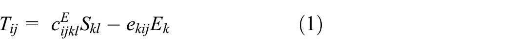
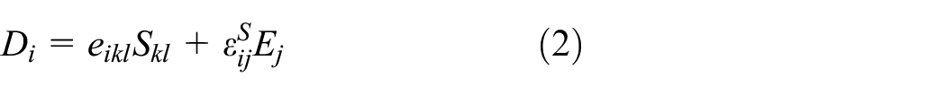
Here,
For large base excitations nonlinear elasticity becomes important and must be considered in the simulations (Stanton et al., 2012). In Stanton et al. (2012) the additional parameters
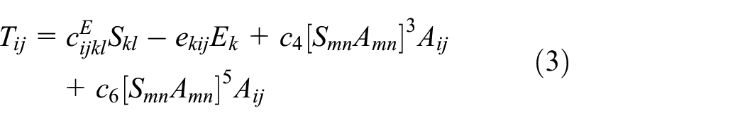
with the structural tensor
Ultimately, after applying the FEM for the piezoelectric problem and the Bossak-Newmark method for direct time integration, the (nonlinear) vector-valued equation to be solved results as
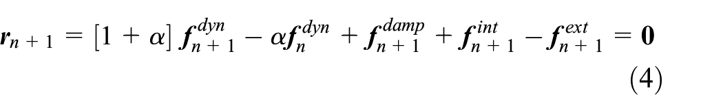
whereby
The coupling between the FEM and ECS simulations is realized via the boundary conditions on the electrode of the piezoelectric structure, the electric current
The electric current
The electric voltage
The current and voltage controlled approaches are used to couple the FEM simulations with an ECS.
3. Simulation of the electric circuit (ECS)
An ECS is a powerful numerical tool for analyzing general electric circuits. In the following, the principle procedure of an ECS for the transient simulation of an electric circuit is presented.
First of all, the ECS automatically formulates the circuit equations for example by means of a modified nodal approach (Ho et al., 1975), which is based on Kirchhoff’s circuit laws. The voltages in the electric circuit nodes and the currents in the branches with voltage sources are considered as unknowns to be determined. Independently of which technique is used in the ECS to obtain the circuit equations, the result is in general a system of nonlinear first order differential algebraic equations of the form

representing the behavior of the coupled elements of an electric circuit (Nichols et al., 1994). Here,
4. Implicit FEM-ECS coupling method
The electromechanical structure is coupled to the electric circuit via the electrode. A real PVEH has a unique electrode voltage
The relevant variables for the implicit FEM-ECS coupling are the electrode voltage
In the presented approach, the FEM and ECS simulations run independently up to their equilibrium states in each time step with their respective prescribed boundary conditions/input variables. Next, the agreement of the electrode voltage
Owing to the implicit character of the coupling method, equilibrium is established between the FEM and ECS simulations at time
4.1. Current controlled coupling without sub-cycling
The current controlled coupling considers the electrode voltage

The electric circuit is simulated with an ECS, resulting in a relation for the electric voltage at the same electrode

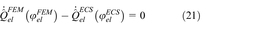
Equilibrium between the FEM simulation and the ECS simulation is achieved when

The coupling method ensures that
As an example, Figure 1 illustrates functions (6) and (7) for a linear electromechanical structure
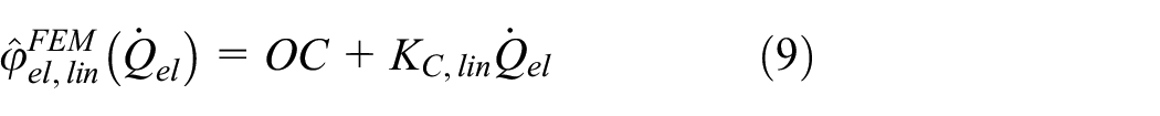
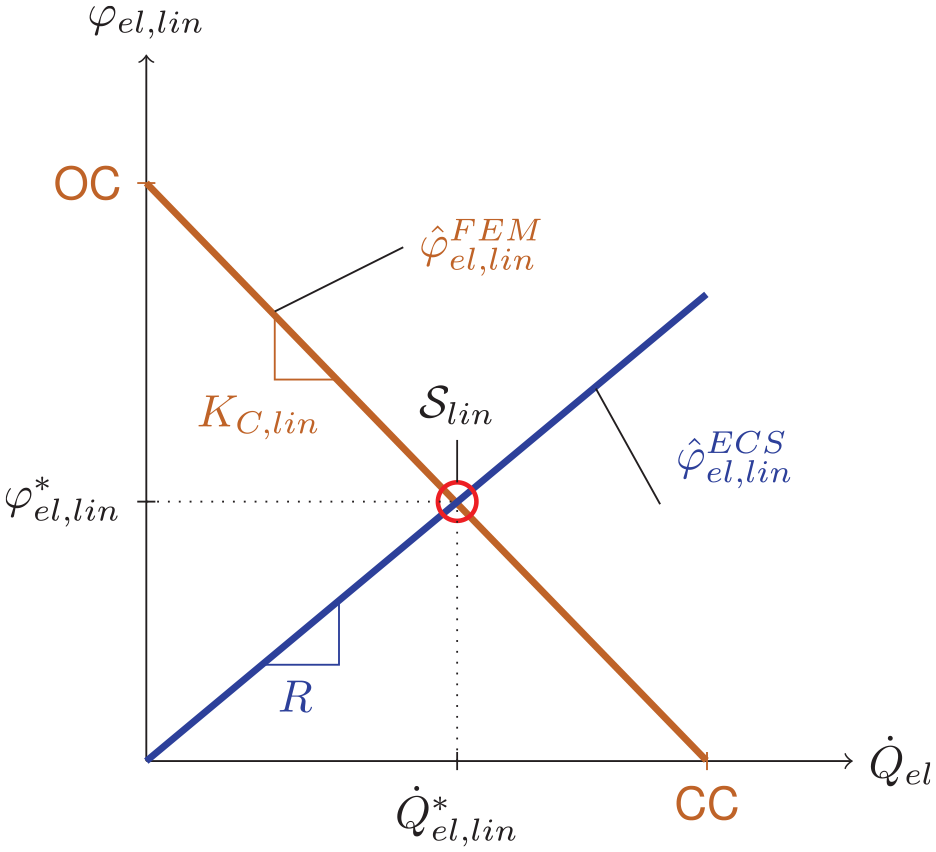
Coupling of a linear electromechanical structure to a load resistor
The relation for the electrode voltage
and also leads to a straight line in Figure 1.
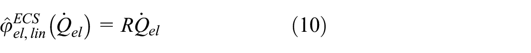
The searched solution
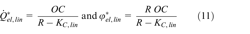
The larger the load resistor, the lower the electric current
In general, the relations for the electromechanical structure and the electric circuit can be nonlinear. Therefore, a numerical approach is necessary to find the solution
The Newton-Raphson method is used to derive the electric voltage on the electrode
Newton-Raphson convergence algorithm between the FEM and ECS simulations for the current controlled coupling.
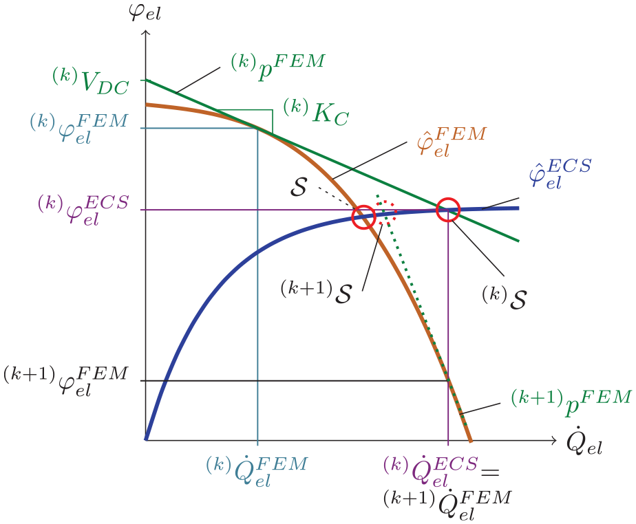
Starting point of the Newton-Raphson method in Figure 2 is the input for the FEM simulation, which is the electric current value
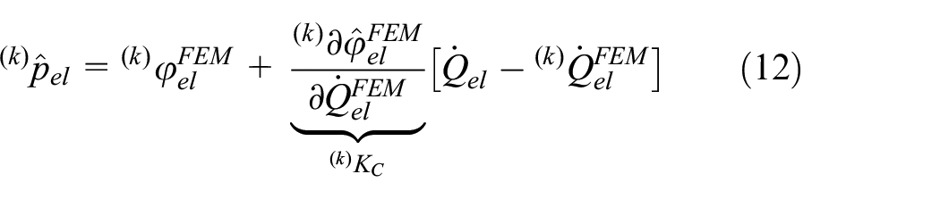
The slope
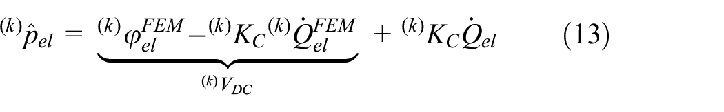
whereby
The linear approximation of the electric behavior of the electromechanical structure
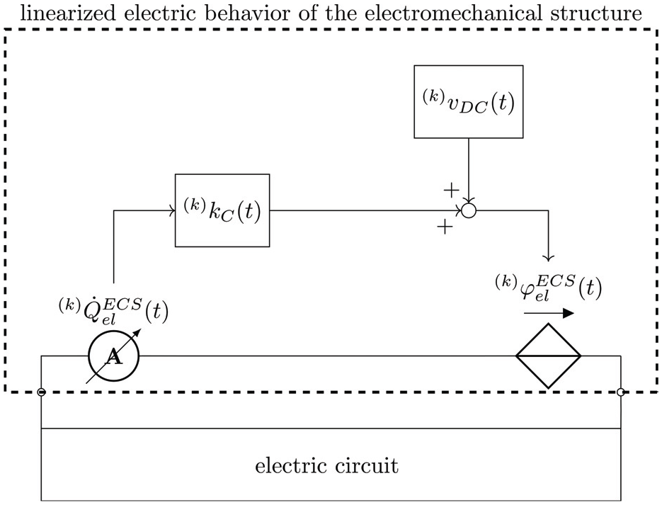
Implementation of the controlled voltage source for the current controlled coupling in the ECS.
For consistency between the time steps, the ECS has to use correct initial values at time


Equations (14) and (15) define the initial conditions for each iteration to ensure consistency. These are used in the current iteration to compute the values at time


The ECS results in the solution
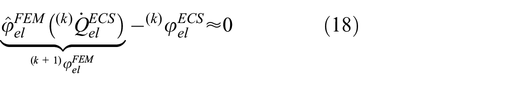
In equation (18), the evaluation of the function

and the algorithm is repeated until convergence is obtained. In case of convergence, the electric current at the FEM-ECS interface is given as

Finally, the complete states of the FEM (e.g. nodal displacements) and the ECS (e.g. voltage values of the circuit elements) simulations are saved. Accordingly, these states are loaded as initial conditions for the computation of the next timestep.
Figure 4 summarizes the algorithm for the current controlled coupling. Starting with the electric current of the previous time step
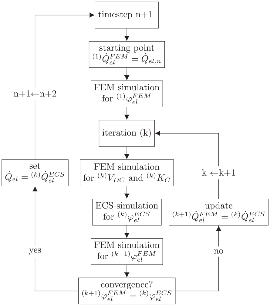
Summary of the algorithm for the current controlled coupling.
4.2. Voltage controlled coupling without sub-cycling
The voltage controlled coupling scheme is quite similar to the current controlled coupling. The electric current
In the FEM simulation, the voltage controlled coupling scheme results in Dirichlet boundary conditions for the electric voltage
In the ECS, the linearized behavior of the electromechanical structure is modeled as a controlled current source, consisting of two time dependent function blocks.
The detailed equations and illustrations of the voltage controlled coupling are given in Appendix A.
4.3. Implicit coupling with sub-cycling
The presented implicit coupling method allows to choose different time step sizes for the FEM and ECS simulations, that is sub-cycling of one method is possible. Then, the coupling takes place at the synchronization points and the time steps for FEM and ECS between these points can be selected independently. Typically, the electrical frequencies in energy harvesting applications are orders of magnitude higher than the mechanical frequencies. Thus, smaller time step sizes are required in the ECS than in the FEM simulations, and sub-cycling of the ECS is desired. The FEM time steps are considered as synchronization points between the two simulation domains and sub-cycling is only applied in the ECS simulation.
In this case intermediate values for the tangents and y-axis intercepts in the interval
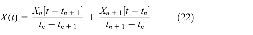
whereby
5. Validation of the implicit coupling
The FEM simulation of the electromechanical structure is implemented based on the open source C++ Finite Element library deal.ii targeted at the efficient solution of partial differential equations (Arndt et al., 2019). This FEM library can perform all steps of electromechanical coupled FEM simulations, including meshing, assembling the system matrix, solving linear systems of equations and post-processing the results, and is used to solve equation (4) for the electromechanical structure. For the simulation of the electric circuit the multiphysics simulator MATLAB/Simulink Simscape is applied, which allows for the simulation of arbitrary electric circuits, for the development of control systems, and, for example, for design optimization. To ensure computational efficiency, the iterative characteristic of the presented implicit coupling method requires that the FEM and ECS software can store and load their internal states to update the initial conditions after the computation of each timestep (Busch, 2012). The current state of the electric circuit simulation can be conveniently saved and loaded in MATLAB/Simulink Simscape and the in-house FEM code also offers this option.
To validate the presented current and voltage controlled FEM-ECS coupling and to demonstrate its capabilities, a unimorph PVEH with different nonlinear electric circuits is simulated. The results of the implicit coupling method are compared against results reported in the literature obtained by explicitly and monolithically coupled FEM-ECS simulations. Moreover, the computational efficiency of the different coupling methods is discussed.
5.1. Unimorph PVEH with half diode bridge circuit
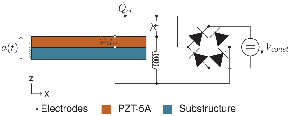
Figure 5 shows a unimorph electromechanical structure introduced in Erturk and Inman (2008) consisting of a layer of substructure and a layer of PZT-5A. The PVEH is excited at its base with a harmonic base acceleration
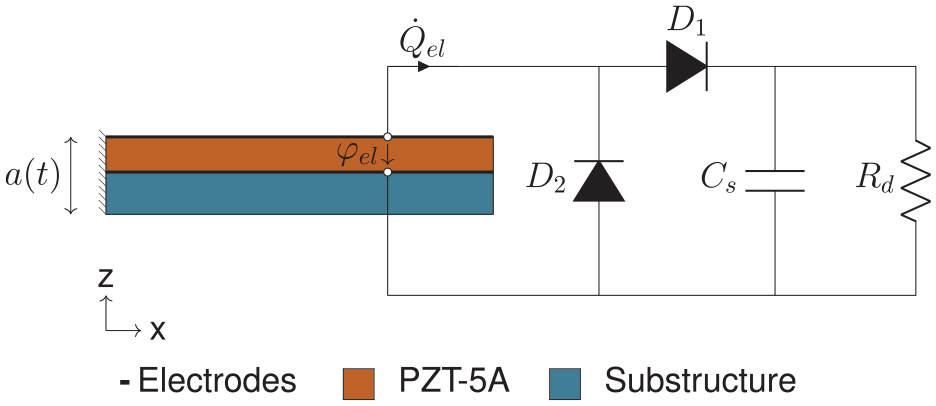
Unimorph PVEH with half diode bridge circuit.
The electric circuit used is a half diode bridge circuit consisting of two diodes
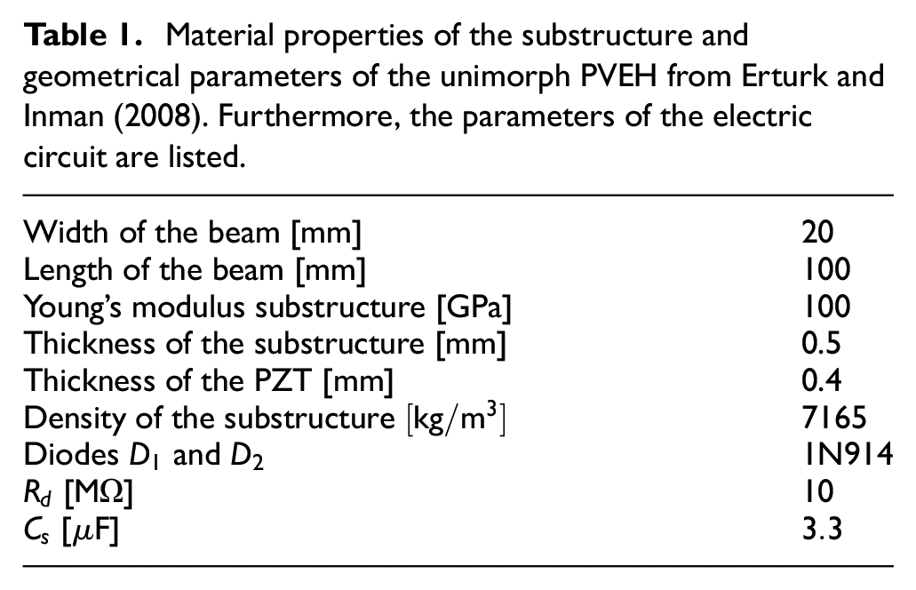
Material properties of the substructure and geometrical parameters of the unimorph PVEH from Erturk and Inman (2008). Furthermore, the parameters of the electric circuit are listed.
For the FEM simulation the electromechanical structure is discretized with 120 quadratic hexahedral elements. The same quadratic ansatz functions are used to approximate the displacements and the electric voltage. For the non-piezoelectric substructure, elements with only mechanical degrees of freedom but without electrical degrees of freedom are used. A constant time step size of
Figure 6 compares the results of the current and voltage controlled coupling approaches against the results of the explicitly coupled FEM-ECS simulation from Elvin and Elvin (2009a). The differences are mainly due to oscillations of the electric voltage
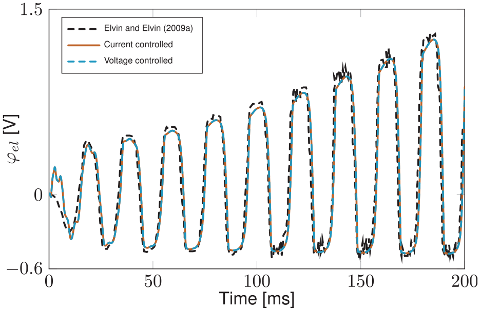
Comparison of the piezoelectric voltage
Furthermore, in Elvin and Elvin (2009a) the accuracy of the explicit coupling method is studied for different numbers of time steps per oscillation period
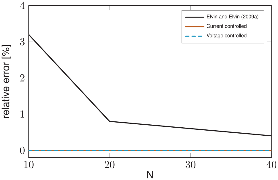
Relative error in the maximum voltage between the explicit coupling in Elvin and Elvin (2009a) and a monolithic simulation and between the proposed implicit voltage and current controlled couplings and a monolithic simulation.
Similarly to Elvin and Elvin (2009a), the accuracy of the proposed implicit coupling method is evaluated by comparing the implicitly coupled FEM-ECS simulation results against monolithic FEM simulations. The load resistance is considered in the monolithic FEM simulations via the vector of external forces, similar to the method presented in Hegendörfer et al. (2022b). Different numbers of time steps per oscillation period
In the implementation of the explicit coupling method in Elvin and Elvin (2009a), the entire time history must be recalculated at each time step, since it is not possible to restart the simulations from a previous time step. This fact leads to a significant unnecessary additional computational effort. In contrast, our implementation using the implicit coupling method can store and load the states of the FEM and ECS simulations for the calculation of each time step to overcome this problem.
It should be noted, that convergence between the FEM and ECS simulations of the unimorph PVEH is achieved in the first Newton-Raphson iteration for both electric circuits, the half diode bridge and the load resistor. Although the half diode bridge circuit is strongly nonlinear, only one iteration is necessary because the electromechanical structure is linear.
5.2. Unimorph PVEH with SSHI circuit
Figure 8 shows the linear unimorph electromechanical structure from the previous example, which is here equipped with an SSHI circuit. A constant voltage
Unimorph PVEH with SSHI circuit.
For details about the SSHI circuit please refer to the literature (e.g. Guyomar et al., 2005; Hegendörfer et al., 2022b; Shu et al., 2007). A self-adaptive switching control for the SSHI circuit is used, which triggers the switch when the piezoelectric voltage
In order to enable efficient and accurate simulations, variable time step sizes are introduced in the FEM simulation: For the process of voltage inversion, during which the switch is closed, a time step size of
Figure 9 compares the results for the electrode voltage
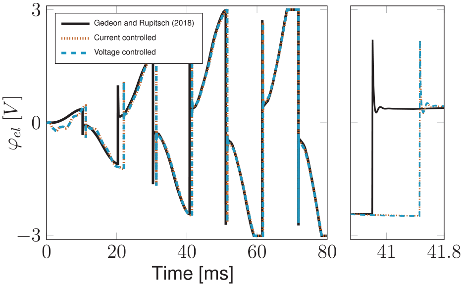
Comparison of the piezoelectric voltage
The results of the current and voltage controlled couplings are almost identical, but there are very small differences due to tolerances of the solver and the numerical evaluation of the slopes
The monolithic FEM-ECS couplings reported in the literature (Aftab et al., 2012; Gedeon and Rupitsch, 2018; Xiang et al., 2018) apply a model order reduction technique to the FEM model. Therefore, the monolithic coupling methods are computationally more efficient than the implicit coupling method using the full FEM model. However, the implicit coupling method can exploit the full capabilities of the FEM for the consideration of nonlinear electromechanical structures. The reduced order models in contrast are limited to linear piezoelectric structures.
Considering the different PVEH simulations, their results with the current and voltage controlled coupling methods agree with the results reported in the literature. It is confirmed that the presented system simulation method with an implicit coupling of FEM and ECS gives accurate results. The presented implicit coupling method can be applied to all FEM and ECS tools that can read and export time step results.
6. Application example
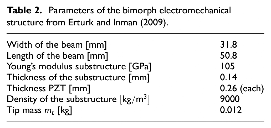
Figure 10 on the left shows a bimorph piezoelectric structure introduced in Erturk and Inman (2009) with a tip mass
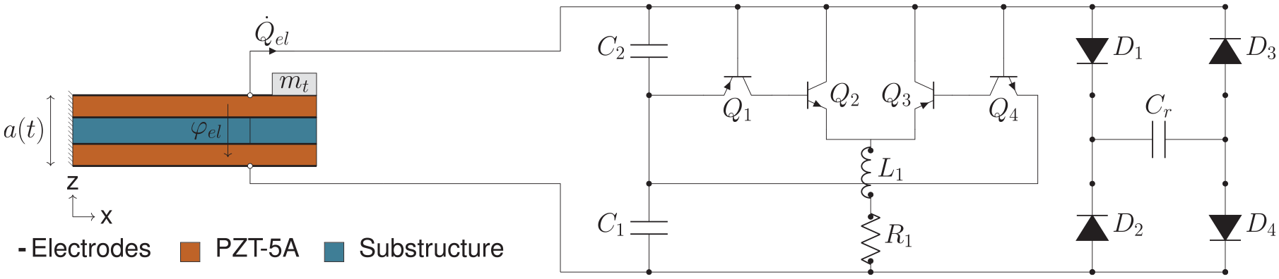
Application example consisting of a nonlinear bimorph electromechanical structure and a self-powered SSHI circuit.
Parameters of the bimorph electromechanical structure from Erturk and Inman (2009).
The nonlinear bimorph electromechanical structure is coupled with an efficient self-powered SSHI circuit presented in Eltamaly and Addoweesh (2017). This SSHI circuit consists of diodes and transistors and is shown in Figure 10 together with the nonlinear bimorph electromechanical structure. One advantage of this SSHI circuit is that only the two capacitors
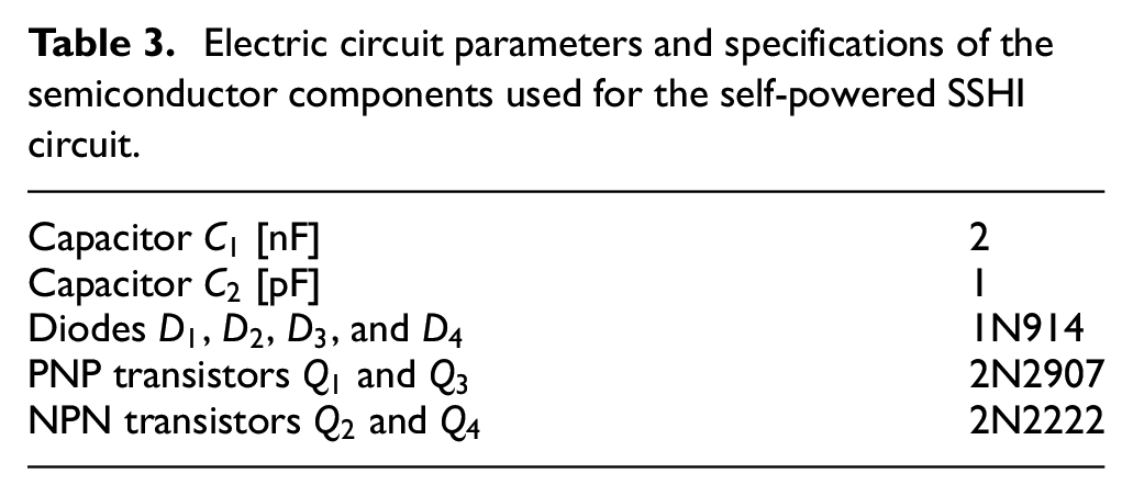
In the MATLAB/Simulink Simscape simulations the same models are available for the semiconductor components as used in the circuit simulator SPICE. For the simulation of the transistors
Electric circuit parameters and specifications of the semiconductor components used for the self-powered SSHI circuit.
Since the simulations are executed in the time domain, discrete time step sizes must be introduced. FEM and ECS simulations must be conducted at each time step, so the time step size significantly affects the accuracy and the computational costs. A smaller time step size means higher computational costs, but the simulations become more accurate. If discontinuities occur in the simulations very small time step sizes are required to resolve them. Conversely, if the states of the simulation do not change rapidly, large time step sizes are desired for computational efficiency. Therefore, efficient simulations in the time domain require an adaptation of the time step sizes to the current conditions in the simulation. Consequently, an algorithm is necessary which adapts the time step sizes automatically to ensure efficient and accurate simulations.
The commercial software Matlab/Simulink Simscape used to simulate the electric circuit provides powerful solvers with automatically adjusted time step sizes. The ECS can run sub-cycles and all solvers of Matlab/Simulink Simscape are available. As a result, the electric circuit can be solved efficiently.
For the adaptive control of the applied time step sizes in the FEM simulation, a purely empirical method, presented in Hibbitt and Karlsson (1979), which is based on limiting a residual calculated between two FEM time steps, is used. Furthermore, to accurately capture the interaction between the FEM and ECS simulations the maximum change of the absolute value of the electrode voltage
In the next step, the ECS simulation results for the SSHI circuit are compared against results reported in the literature to validate the ECS analysis. Finally, a shock-like base excitation is applied to the piezoelectric structure and the results of the coupled FEM-ECS simulation are discussed.
6.1. Validation of the ECS simulation
A similar self-powered SSHI circuit as presented in Figure 10 is also considered in Zhang et al. (2021), coupled to a linear electromechanical structure. In Zhang et al. (2021), the response of the linear piezoelectric structure for the first vibration mode is represented by means of an equivalent circuit model, to allow the simulation of the PVEH in an ECS. To validate our Matlab/Simulink Simscape model of the SSHI circuit the same equivalent circuit model of the electromechancal structure is simulated together with the SSHI circuit. The same storage capacitance
Figure 11 compares the results for the voltage across the storage capacitor
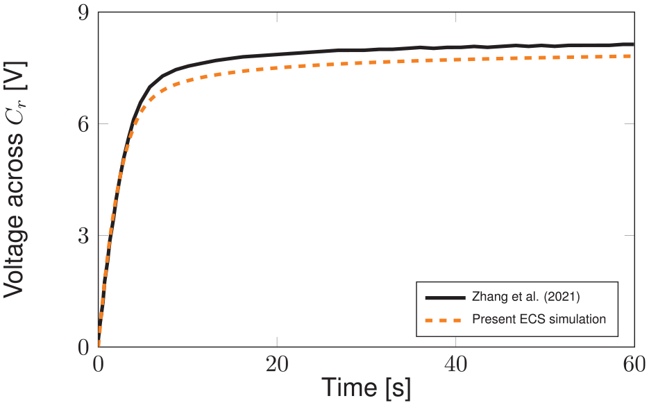
Comparison of the present Matlab/Simulink Simscape simulation results for the self-powered SSHI circuit against the results reported in Zhang et al. (2021).
6.2. Shock-like excitation
A shock-like base excitation
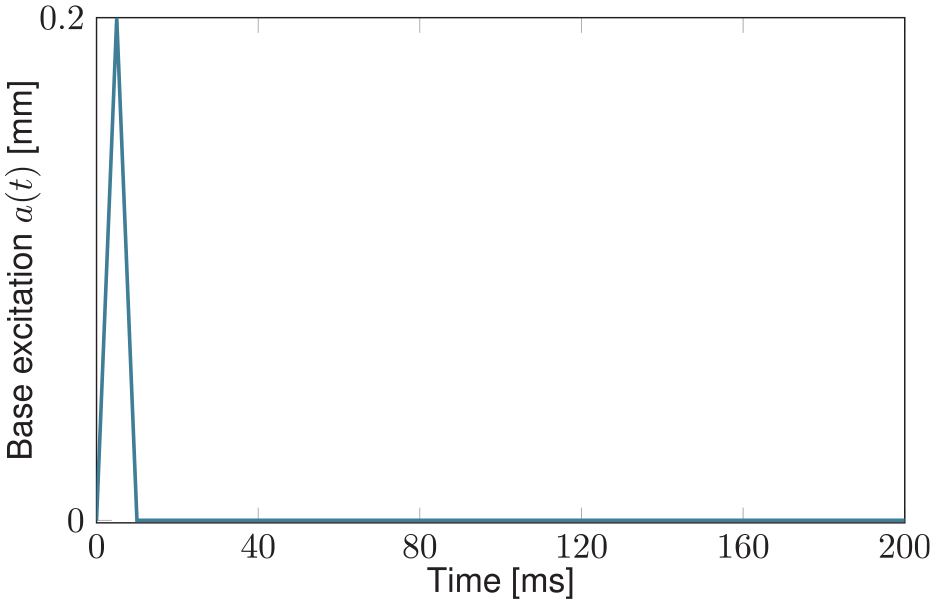
Shock-like base excitation
Due to the piezoelectric effect, the mechanical and electrical behavior of the bimorph electromechanical structure influence each other. Taking into account nonlinear elasticity, the electric voltage
Figure 13 presents the time signal of the electrode voltage
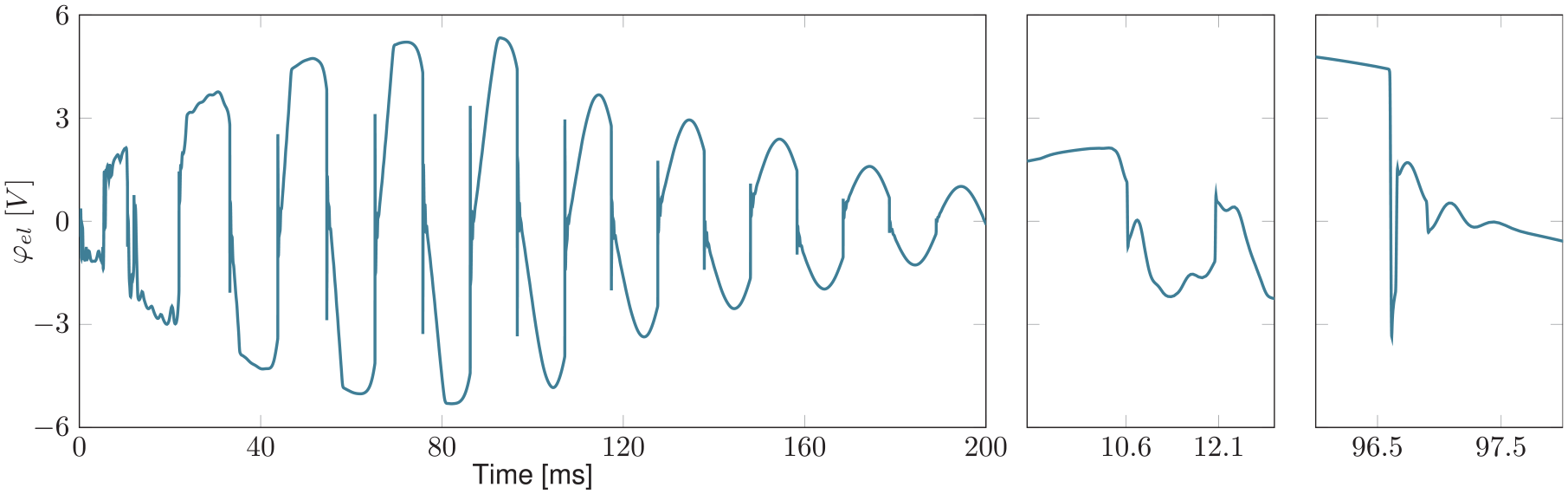
Time signal of the electrode voltage
During the first around
For practical applications, an accurate evaluation of the mechanical stresses in the electromechanical structure is paramount. It depends on them whether the electromechanical structure fails during operation. Considering that PZT-5A is a brittle ceramic material, Rankine’s theory is applied, which states that failure occurs when the maximum principal stress at any point reaches a value equal to the maximum dynamic tensile strength of PZT-5A. An advantage of using the FEM to simulate the electromechanical structure is, that the mechanical stresses in the electromechanical structure can be precisely evaluated. Figure 14 shows the time evolution of the maximum principal stresses in the PZT-5A layers. For times
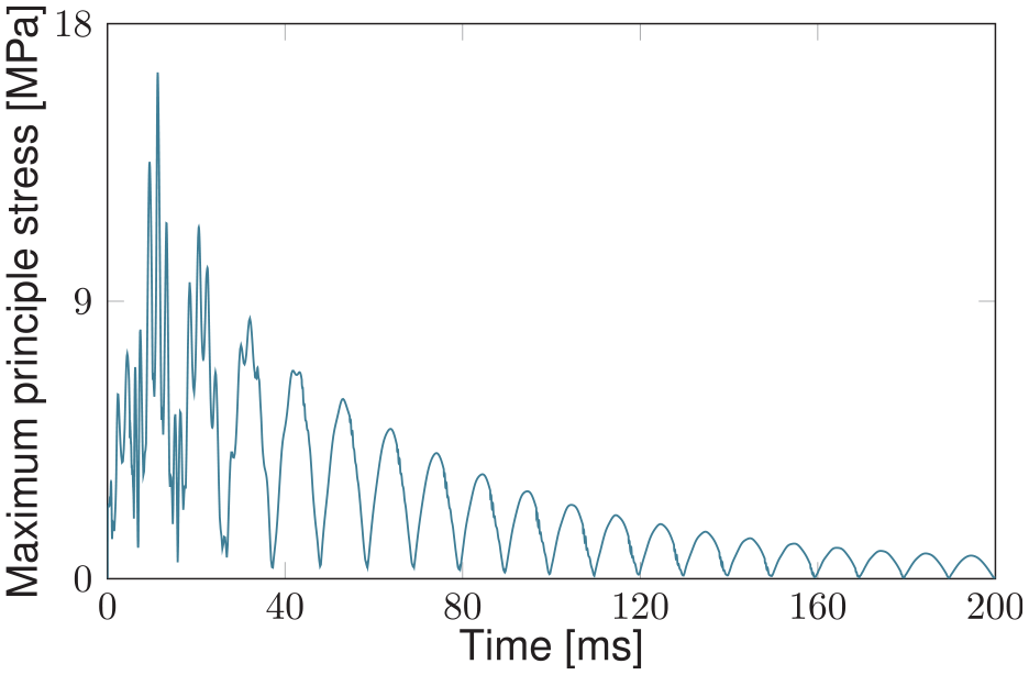
Time evolution of the maximum principal stresses in the PZT-5A layers of the electromechanical structure.
The precise consideration of the behavior of the electric circuit and the nonlinear electromechanical structure leads to a realistic simulation of a PVEH. All mechanical and electrical quantities are available in the simulation. As a result, the practicality of the presented implicit coupling method for the simulation of PVEHs is demonstrated.
7. Conclusion
This contribution addresses the problem of the coupled simulation of a PVEH consisting of an electromechanical structure and an electric circuit which influence each other. The system simulation method presented allows the FEM to be applied to the simulation of the electromechanical structure and an ECS to be used for the electric circuit by means of an implicit coupling. The full capabilities of the FEM can be exploited without restrictions and the complete set of 3D coupled piezoelectric equations is solved. Varying mechanical boundary conditions and nonlinearities of the electromechanical structure, which are essential characteristics of PVEHs, can be taken into account. Moreover, using an ECS allows for the consideration of arbitrary and nonlinear electric circuits. In summary, no simplifications, which could limit the applicability of the method, are introduced in the FEM or ECS simulations. Consequently, the proposed system simulation method allows for the simulation of arbitrary PVEHs and combines the advantages of the FEM and of an ECS.
The implicit coupling at the interface between the FEM and ECS simulations is realized with the Newton-Raphson method. In the case of a linear electromechanical structure, the implicit coupling method achieves convergence in the first Newton-Raphson iteration, regardless of the electric circuit. Moreover, in the case of the nonlinear bimorph electromechanical structure, the presented FEM-ECS coupling method requires only a few iterations between the nonlinear FEM and ECS simulations, which confirms the rapid convergence behavior of the presented coupling method. Furthermore, sub-cycling of the ECS ensures numerical stability of the implicit coupling method even if the time period between two synchronization points changes dramatically. In addition, the FEM-ECS coupling is implicit, meaning that significantly larger time steps can be used compared to an explicit coupling.
The presented implicit FEM-ECS coupling method is validated against a unimorph PVEH equipped with different nonlinear electric circuits from literature. Moreover, an application example consisting of a nonlinear electromechanical structure and a self-powered SSHI circuit is considered and a shock-like base excitation is applied. These examples demonstrate the applicability of the presented implicit coupling method for efficient simulations of general nonlinear PVEHs.
The main limitation of the presented implicit coupling method is the high computational cost, which is generally a problem in transient FEM simulations. Taking into account general nonlinear electromechanical behavior requires transient simulations and the associated effort is not always avoidable. The consideration of both complicated electromechanical structures and long time histories leads to long simulation times, which can make the implicit coupling method impractical in some cases.
It should be noted that the presented FEM-ECS coupling method is not limited to energy harvesting applications, but can also be used for simulations of general smart structures and devices.
Footnotes
Appendix
Appendix B: Material parameters
In the following, material parameters for PZT-5A are provided that are used in this contribution.
The nonlinear coefficients for the nonlinear piezoelectric constitutive law (3) were identified in Stanton et al. (2012) as
Declaration of conflicting interests
The authors declared no potential conflicts of interest with respect to the research, authorship, and/or publication of this article.
Funding
The authors disclosed receipt of the following financial support for the research, authorship, and/or publication of this article: This work was supported by the Deutsche Forschungsgemeinschaft under GRK2495/C [grant number 399073171].