
Abstract
Piezoelectric vibration-based energy harvesters consist of an electromechanical structure and an electric circuitry, influencing each other. We propose a novel approach that allows a finite element based system simulation of nonlinear electromechanical structures coupled to nonlinear electric circuitries. In the finite element simulation the influence of the electric circuit on the electromechanical structure is considered via the vector of external forces, using an implicit time integration scheme. To demonstrate the applicability of the new simulation method an active power circuit is considered. Several examples of piezoelectric vibration-based energy harvesters, connected to standard or synchronized switch harvesting on inductor (SSHI) circuits, showing linear or nonlinear mechanical behavior, are studied to validate the proposed simulation method against numerical results reported in the literature. The advocated method allows for consistent and efficient simulations of complete nonlinear energy harvesters using only one software tool.
Keywords
1. Introduction
Energy harvesting is of great importance in the digital world to enable self-powered systems like wireless sensors or other small electronic components. Vibration-based energy harvesting converts ambient vibration energy to electrical energy. Compared to other energy conversion principles like electrostatic (Mitcheson et al., 2004) or electromagnetic (Glynne-Jones et al., 2004; Williams and Yates, 1996) transduction mechanisms the advantage of the piezoelectric effect (Roundy et al., 2004; Rupitsch, 2019) is the high power density and the ease of application of piezoelectric materials (Erturk and Inman, 2011).
A piezoelectric vibration-based energy harvester (PVEH) is composed of an electromechanical structure and an electric circuit to extract the energy. Various types of piezoelectric transducers are proposed in the literature, for example unimorph (a single piezoelectric layer bonded to a substrate layer) and bimorph (a single substrate layer with two symmetric piezoelectric layers bonded on each side) cantilever beams (Safaei et al., 2019). Beam-type harvesters are very efficient when excited at their resonance frequency but become less efficient when the excitation is below or above their resonance frequency. Numerical simulations are a valuable tool to develop PVEHs as they increase the understanding of the energy harvesting problem and allow to match the electromechanical structure and the electric circuit according to the excitation range.
The electromechanical structure and the electric circuit influence each other. Therefore, an accurate prediction of the behavior of a PVEH requires accurate modeling of both the electromechanical structure and the electric circuit.
Analytical solutions are possible for relatively simple geometries of the electromechanical structure in combination with simple electric circuits. Erturk and Inman (2008b) clarified some issues in the mathematical modeling of piezoelectric-based energy harvesting. They identified some problems of single degree of freedom models, mainly related to inaccuracies in the modeling of the electromechanical coupling. Furthermore, they suggested an analytical distributed parameter model based on the Euler-Bernoulli beam theory (Erturk and Inman, 2008a). These analytical models are valuable tools to increase understanding, to get fast solutions for simple PVEH and to validate numerical simulations (e.g. De Marqui et al., 2009; Rupp et al., 2009; Yang and Tang, 2009). To overcome the restrictions of the analytical methods, numerical methods as the Finite Element Method (FEM) are frequently applied to simulate more complex or arbitrarily shaped PVEHs.
While being computationally expensive, the FEM allows for optimization of the electromechanical structure (Noh and Yoon, 2012; Park et al., 2012; Wein et al., 2013), for modeling of nonlinear electro-elastic behavior (Vu et al., 2007), for detailed material parameter analysis (Daniels et al., 2013), for the consideration of multiple segmented plate structures with different electric circuit connection patterns (Lumentut and Shu, 2018, 2021) and, for example, for the simulation of crack propagation (Abdollahi and Arias, 2012). Various approaches are introduced in the literature how to couple the simulation of electric circuits with an FE analysis of electromechanical structures.
In Elvin and Elvin (2009) an explicit coupling is presented, which utilizes an available FEM package for a purely mechanical simulation and a standard circuit simulation software for the electric circuit. The coupling between the circuit simulation and the FE simulation is done via introducing equivalent piezoelectric loads in the mechanical model and applying equivalent electric voltages in the electric model. As already concluded in Elvin and Elvin (2009), the drawback of this method is that the explicit solution technique can be computationally expensive.
In Zhu et al. (2009) an electromechanical structure with an attached load resistance is solved with the commercial FE Software ANSYS. However, this system simulation is restricted to a combination of linear circuit elements. De Marqui et al. (2009) also considered only a load resistance as a passive electric circuit and developed an electromechanically coupled finite element plate model for predicting the electrical power output of piezoelectric energy harvester plates. Furthermore, commercial FE packages are utilized to validate analytical models (Schoeftner and Buchberger, 2013), to simulate electromechanical structures with simple electric circuits (Abdelkefi et al., 2014; Akbar and Curiel-Sosa, 2019) or to identify parameters for an analytical modeling approach (Xiong and Oyadiji, 2014).
In Wu and Shu (2015) an equivalent steady-state load impedance of a standard and an SSHI circuit is derived. The load impedances can be directly included in available FE software to allow for steady state simulations of PVEHs. Notably, this approach is extensible to multiple piezoelectric oscillators. Cheng et al. (2016) proposed two coupled models: The first one is an equivalent circuit model of the electromechanical structure. The equivalent circuit model parameters are estimated by FE analysis. The second one integrates the impedance of the circuit into a FE framework. Furthermore, a comparison of the two modeling techniques is carried out.
Recently, Gedeon and Rupitsch (2018) developed a system simulation method based on the FEM. The matrices of a FEM discretization are directly imported into an electric circuit simulation with Simscape (Matlab/Simulink). All capacitive and electromechanical coupling effects are included and a model order reduction technique is applied to the FEM simulation to reduce the computational costs. No nonlinearities of the electromechanical structure are considered in this work.
However, all FE based methods reported in the literature, which are not coupled to circuit simulation software, are limited to linear circuit elements and passive electric circuits. The FE based methods, which are combined with an external circuit simulation tool consider only linear electromechanical structures or the coupling between the electromechanical structure simulation and the electric circuit simulation is not very efficient.
To overcome the mentioned drawbacks of existing FE methods for PVEHs, a novel system simulation approach for nonlinear electric circuits coupled to nonlinear electromechanical structures using only the FEM is proposed. The applicability of the presented approach is demonstrated by simulating a unimorph PVEH attached to an SSHI electric circuit. Furthermore, a bimorph PVEH with nonlinear elastic behavior is considered in combination with nonlinear electric circuitry.
2. Governing equations of piezoelectricity
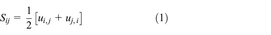
Within this contribution index notation in accordance to Institute of Electrical and Electronics Engineers (IEEE) (1988) is applied. The piezoelectric body

Here,

Here,

Here,
Here,
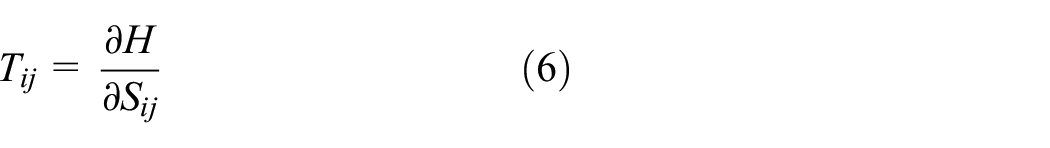
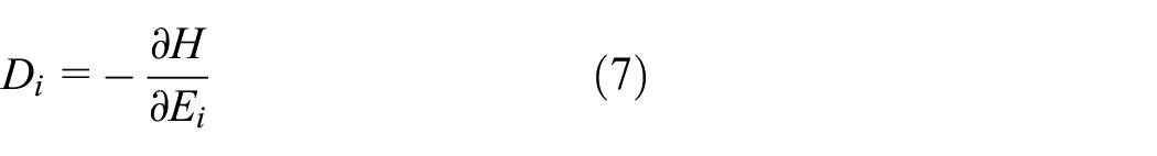
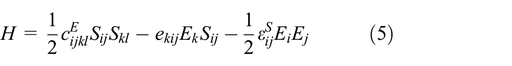
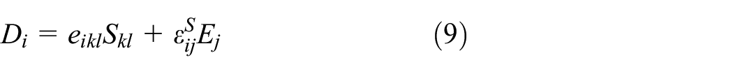
For details about the aforementioned relations please refer to the literature (IEEE, 1988; Rupitsch, 2019). The linear piezoelectric constitutive law resulting from equations (5)–(7) reads
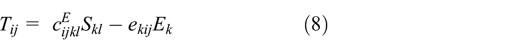
For small strains, which for PVEHs are usually related to small base accelerations, the linear piezoelectric model gives satisfactory results. However, in Stanton et al. (2012) the influences of nonlinearities in the elastic, electroelastic and damping behavior were analyzed. It was shown that a nonlinear elastic material model results in better agreement with experimental results. The model was introduced in a 1D setting and postulates a nonlinear polynomial function for the stress

with the additional parameters
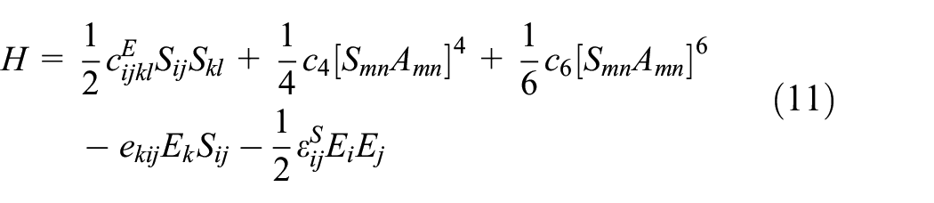
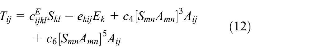
with the structural tensor
Equations (1)–(4) along with the linear constitutive law (equations (8) and (9)) or the nonlinear constitutive law (equations (9) and (12)) can be solved with appropriate boundary conditions (Lerch, 1990)


Here, the prescribed surface traction
3. Discretization of the equations
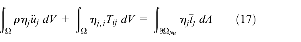
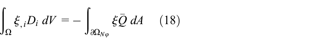
A fundamental step of the FEM is to transform the partial differential equations from their strong formulation (equations (3) and (4) along with equations (1) and (2), a constitutive law and boundary conditions) into their weak formulation. To obtain the desired weak formulation, equation (3) is multiplied by the vector-valued test function
In the FEM, the domain
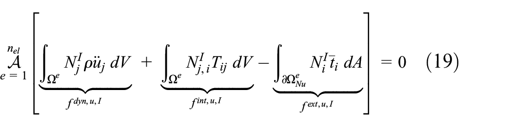
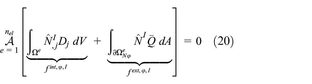
whereby


Here,
The coupling to an electric circuit is easier if the electric surface current

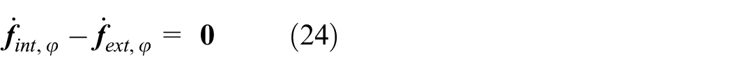
These equations are quite general as they allow to introduce nonlinearities in the material model (via
4. Linear system simulation
When applying the linear piezoelectric constitutive law (equations (8) and (9)) the forces in equations (23) and (24) depend linearly on the unknown mechanical displacements and electrical voltages. Utilizing
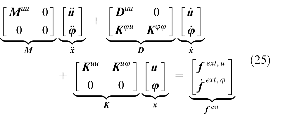
whereby
Within this contribution it is assumed that
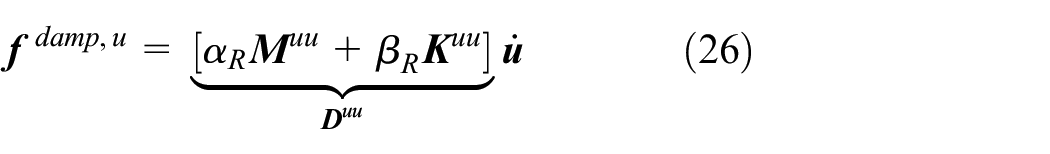
with the Rayleigh-coefficients
4.1. Coupling to electric circuits
Within a FE framework the existence of an electrode on a surface reduces the number of free voltage degrees of freedom to exactly one on this surface. All voltage degrees of freedom on an electrode must have the same value
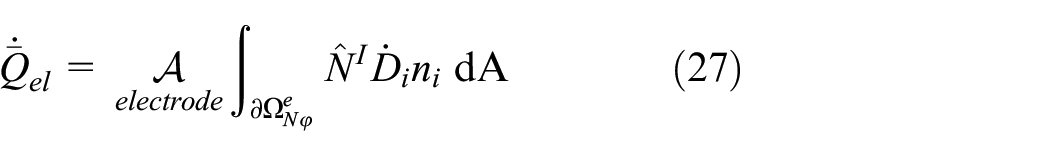
Both,
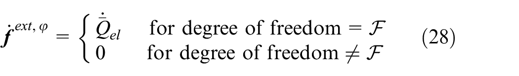
To consider the behavior of different electric circuits in the FE simulation, various functional relations between the current
This functional relation will be specified for two different electric circuits in the example section. The outflowing current affects the mechanical displacement and the electric voltage as energy is extracted from the electromechanical structure. This modeling approach is extendable to multiple electrode configurations of a PVEH.
4.2. Time discretization
Energy harvesting is a dynamic application since its objective is converting vibrational (dynamic) energy to the electric domain. Modeling a PVEH and ignoring for example the resonance phenomenon or using static deflections patterns lead to fundamentally incorrect results (Erturk and Inman, 2008b). The importance of dynamic effects in energy harvesting necessitates the consideration of inertia and damping effects. The Bossak-Newmark scheme is applied to directly integrate equation (25) in time. This direct time integration scheme allows to capture all of the above mentioned effects. For linear problems the implicit Bossak-Newmark scheme is defined as (Wood et al., 1980)

with
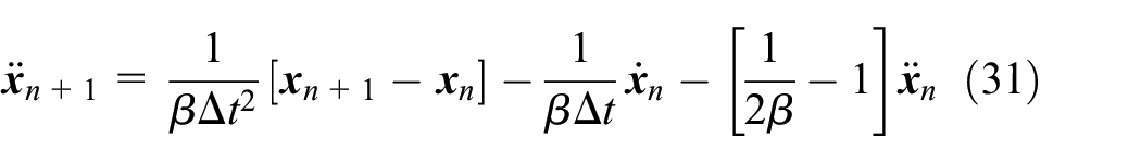
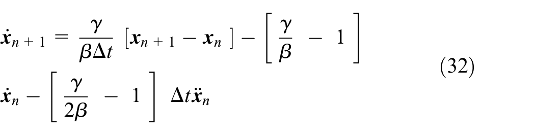
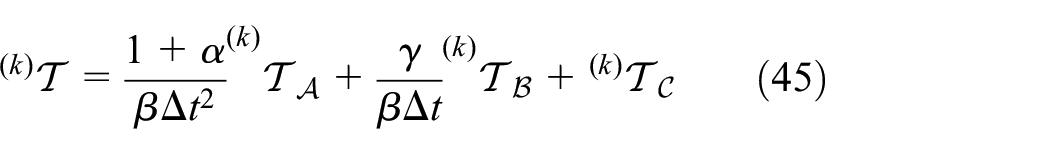
Here,
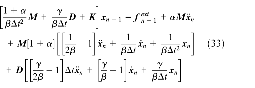
Equation (33) allows for implicit transient simulations of linear electromechanical structures along with linear electric circuits. The presented system simulation method is implemented based on the open source C++ software library deal.ii targeted at the computational solution of partial differential equations (Arndt et al., 2019).
4.3. Linear electromechanical structure with standard electric circuit
A harvesting structure is oscillating during operation and naturally produces alternating electrical signals. Charging a storage component such as a battery or a capacitor requires a stable DC signal (Erturk and Inman, 2011). This necessitates the use of an AC-DC converter in the electric circuit. The simplest way of doing this is to use a diode bridge to supply the rectified voltage to an energy storage element (Gedeon and Rupitsch, 2018). This standard electric circuit is shown in Figure 1 and consists of a full-wave diode rectifier and a battery for energy storage. The electromechanical structure is open circuit and

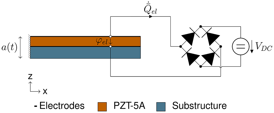
Unimorph PVEH with a standard electric circuit.
When

The conductive voltage

The typical waveforms of
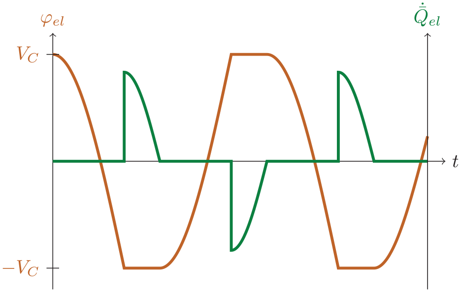
Typical waveforms of
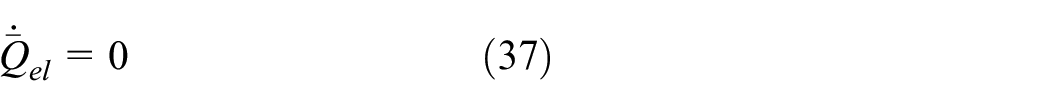
Within the FE based system simulation, the difference between the standard circuit and the open circuit mode is the temporary limitation of
Case 1: This is the open circuit case, which can be simply modeled via a homogenous Neumann boundary condition in a FE simulation.
Case 2: In this case

In case 2 the current can be computed in a postprocessing step using equation (27). Both cases can be simulated with a standard implementation, however, the switching between them has to be provided:
Each new time step
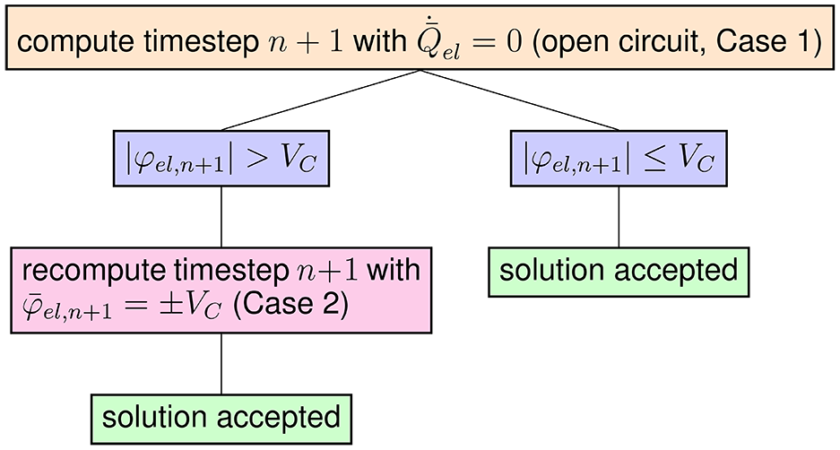
Logic for the definition of boundary conditions for the FE simulation of an electromechanical structure with a standard electric circuit.
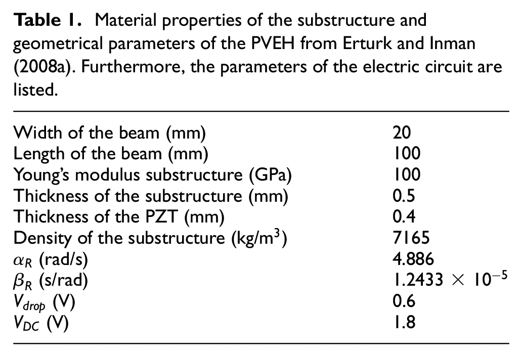
As an application example the unimorph electromechanical structure from Erturk and Inman (2008a) is used and a standard electric circuit is added. Figure 1 shows the considered PVEH. A constant voltage
Material properties of the substructure and geometrical parameters of the PVEH from Erturk and Inman (2008a). Furthermore, the parameters of the electric circuit are listed.
The PVEH is excited at its base with a harmonic base acceleration
Figure 4 shows the time response of
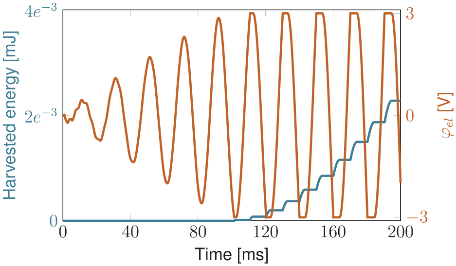
Time signal of
At time
Furthermore, the unimorph electromechanical structure was simulated in open circuit mode and for different electric load resistances in both time and frequency domain. The FE computations agree well with the results of the analytical theory of Erturk and Inman (2008a), which verifies that the presented numerical approach gives correct results.
5. Nonlinear system simulation
A linear description of the energy harvesting problem is no longer possible when more sophisticated electric circuits are considered, or nonlinearities of the electromechanical structure have to be taken into account.
In these cases, the particular forces in equations (23) and (24) do not depend linearly on the displacements and the electric voltage anymore. Therefore, the following nonlinear residuum equation has to be solved
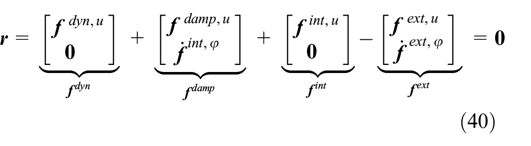
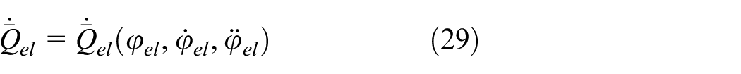
The coupling to nonlinear electric circuits is included in the external force
5.1. Time discretization and solution
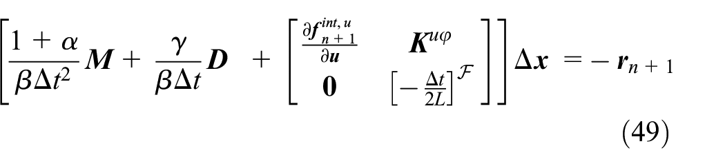
The Bossak-Newmark method applied to the nonlinear equation (40) results in
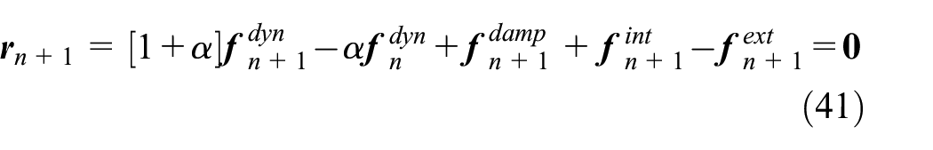
Here,
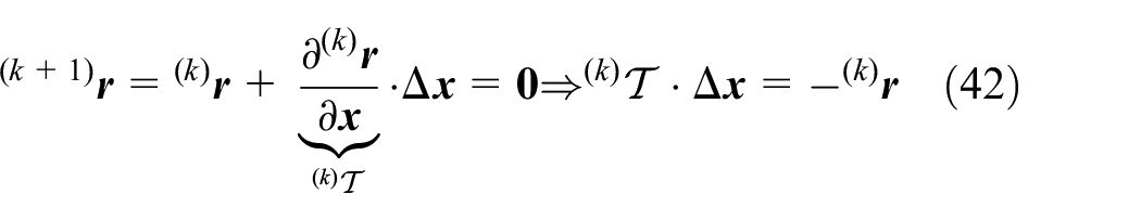
Here,

Subsequently,
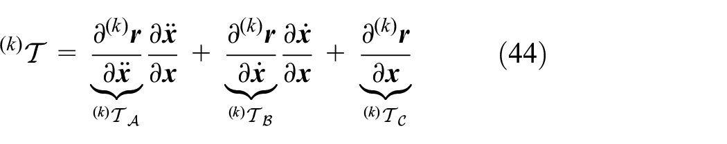
with the tangent submatrices
5.2. Linear electromechanical structure with SSHI circuit
The so called synchronized switch damping technique was introduced by Richard et al. (1999) to address the problem of vibration damping for mechanical structures. Based on this technique Guyomar et al. (2005) derived the SSHI circuit for energy harvesting applications. It was reported that the SSHI circuit can increase the harvested power by up to 900% as compared to a standard circuit depending on both, the electromechanical coupling of the system as well as the excitation signal (Badel et al., 2006; Guyomar et al., 2005).
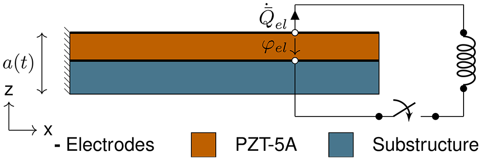
Figure 5 presents the unimorph electromechanical structure from the previous example coupled to an SSHI circuit. The SSHI circuit adds a switch and an inductance (
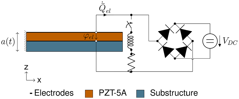
Unimorph PVEH with an SSHI circuit.
Both, the inductance and the switch are connected in parallel to the piezoelectric element. A self-adaptive control of the switch is applied that triggers on the maxima and minima of
The switch is closed when

When the switch is closed the rectifier bridge is in open circuit mode and the inductance is connected to the electromechanical structure. The piezoelectric element acts like a capacitance and thus results in an electric resonant circuit consisting of the piezoelectric capacitance and the inductance. Hence, the electric voltage and the electric current start to oscillate as soon as the switch is closed. The switch is opened again when the current in the inductor is zero-crossing, which results in an inversion of
Figure 6 presents the typical waveform of
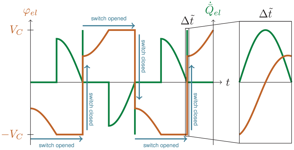
Typical waveforms of
The situation when the switch is opened is simulated similarly as in the previous example (Cases 1 and 2). When the switch is closed the influence of the inductance on the electromechanical structure is considered via an inhomogeneous Neumann boundary condition, integrating equation (46) in time (Case 3).
By applying the implicit second-order accurate trapezoidal rule,
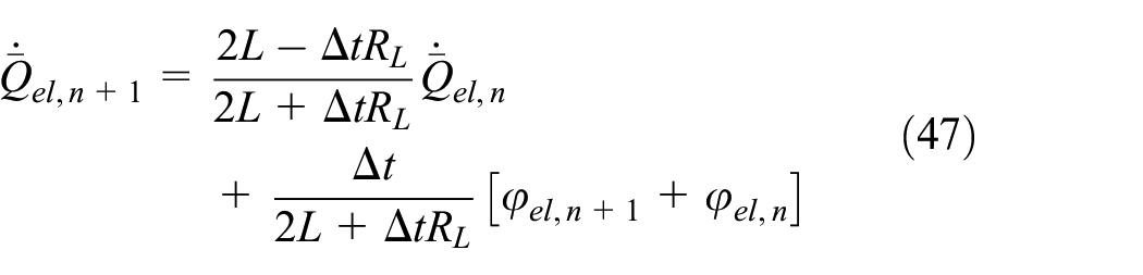
This relation for
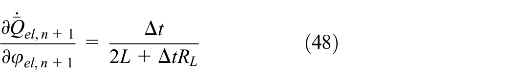
which is placed on the main diagonal of the tangent submatrix for the corresponding degree of freedom
In the following, the logic of the self adaptive SSHI circuit is described: Assume that the switch is opened at time
If
If
If
If the switch is closed at timestep
If the direction of
If the current in the inductance is zero-crossing, that is
In Figure 7 the logic of the SSHI circuit is summarized. Furthermore, it has to be prevented that the switch is triggered at inappropriate times. After closing the switch,
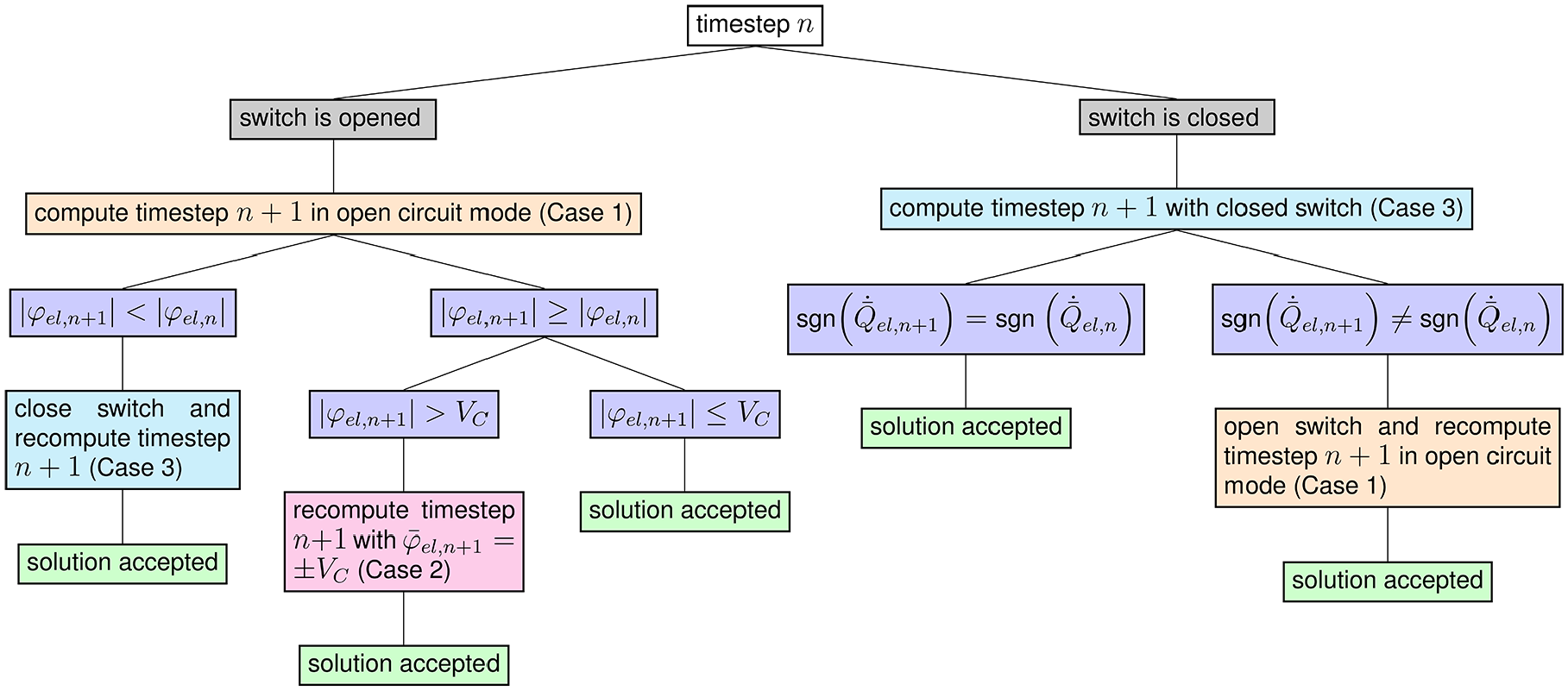
Logic for the definition of boundary conditions for the FE simulation of an electromechanical structure with an SSHI circuit.
To validate the proposed simulation method a PVEH with SSHI circuit is simulated and the results are compared with results from literature. To this end, the same unimorph electromechanical structure from the previous chapter along with an SSHI circuit (
In order to efficiently and accurately simulate the system, variable time step sizes are introduced. The voltage inversion (during which the switch is closed) requires the smallest time step of
Figure 8 compares the resulting electric voltage computed with the presented FE simulation against the results obtained from a simulink simulation of a reduced model of Gedeon and Rupitsch (2018) for the SSHI circuit. The largest differences between the results of the presented method and this reduced model occur during the instationary settling process. After a time span of about 45 ms a very good agreement of the two models can be observed. This overall good agreement verifies that the presented FE system simulation approach is correct.
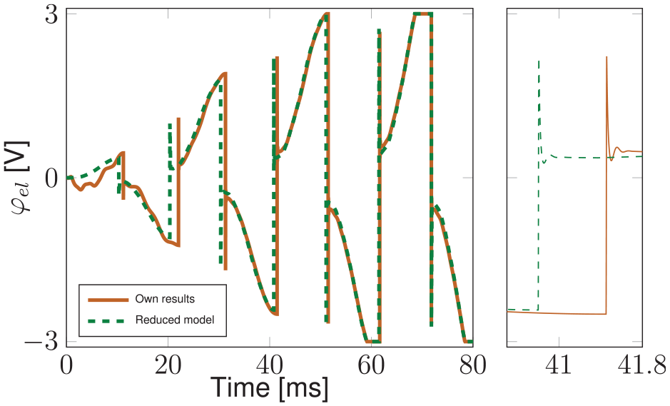
Comparison of
Furthermore, Figure 9 shows
Time signals of
To investigate the influence of the parasitic resistance of the inductance
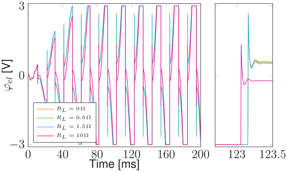
Time signals of
For the considered inductance (
In the open circuit mode, the SSHI circuit works as a Synchronized Switch Damping and thus reduces the displacements (Richard et al., 2000). The presented simulation framework is fully coupled and accounts for this damping phenomena, in addition to the damping which results from the harvested energy. To illustrate this functionality of the simulation framework, a unimorph electromechanical structure with an electric circuit of the synchronized switch damping on inductor (SSDI) technique is simulated. The SSDI circuit consists of a switch and an inductance, compare to Figure 11. Similar to the SSHI technique, the switch is closed when
Unimorph electromechanical structure with an SSDI circuit.
In the simulations, the same unimorph electromechanical structure with the same mechanical, electrical, and excitation parameters as in the previous example is used. Figure 12 presents the piezoelectric voltage
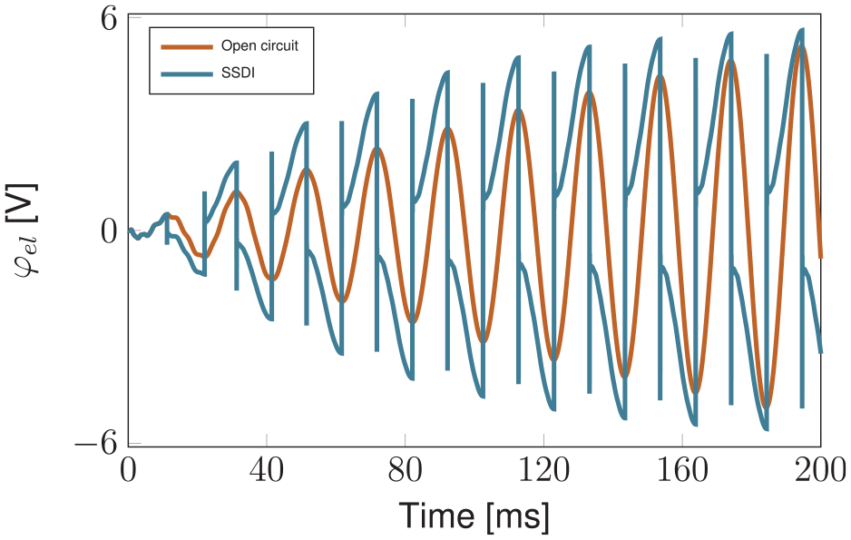
Comparison of the piezoelectric voltage
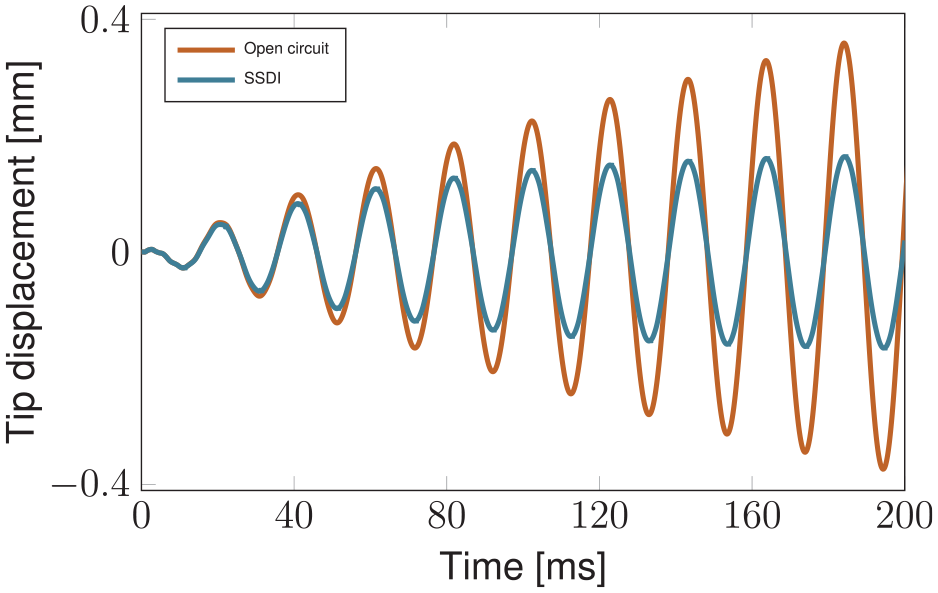
Comparison of the tip displacement of the open circuit configuration and the SSDI configuration.
5.3. Nonlinear electromechanical structure with SSHI circuit
In the following the applicability of the presented system simulation approach for nonlinear electromechanical structures combined with nonlinear electric circuitry is demonstrated. An application example is considered that is restricted to nonlinear elasticity since this is the primary source of nonlinearity in energy harvesting applications (Stanton et al., 2012). Other possible sources of nonlinearities like geometric nonlinearities (Behjat and Khoshravan, 2012), nonlinear damping (Stanton et al., 2012; Yang and Upadrashta, 2016) as well as strong electric fields (Beige, 1983), and others are neglected.
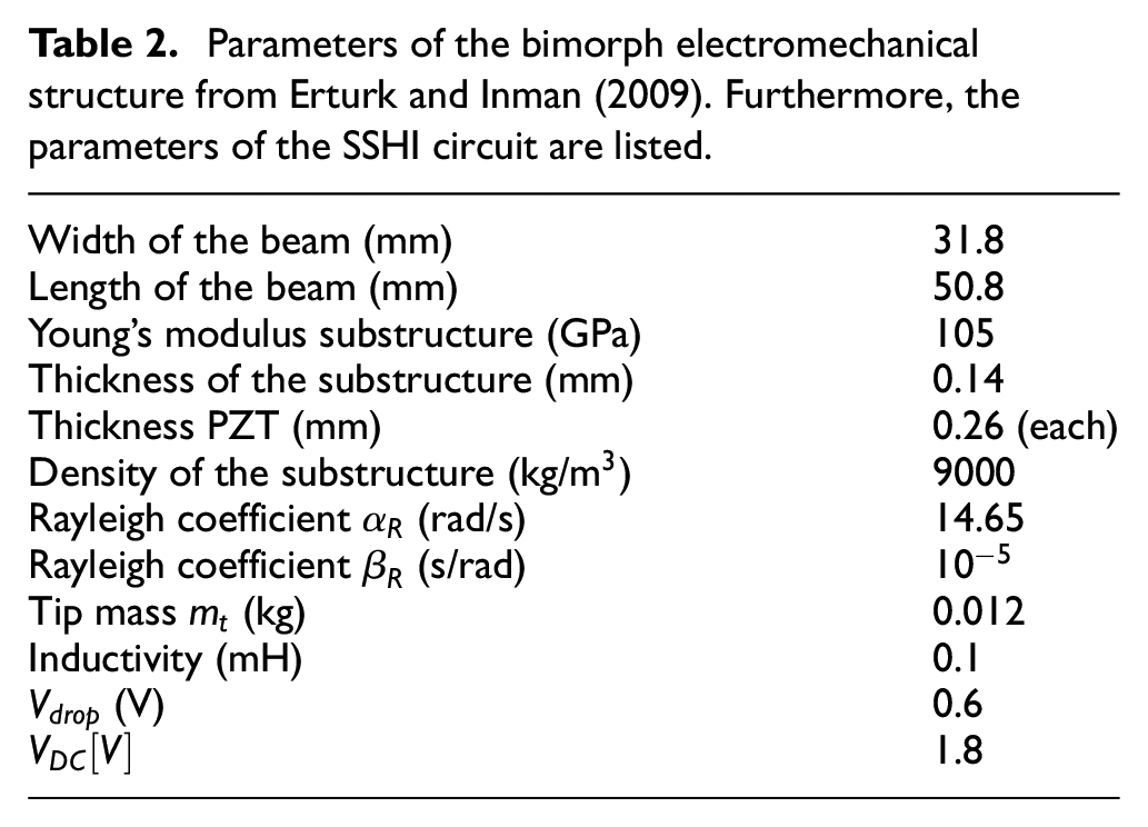
The SSHI circuit from the previous chapter is added to the bimorph electromechanical structure introduced in Erturk and Inman (2009). The cantilevered bimorph electromechanical structure consists of two layers of PZT-5A (material parameters in the Appendix) bracketing a passive substructure layer. The piezoceramic layers are poled in opposite directions. To consider nonlinear elasticity, the nonlinear constitutive law for PZT-5A is applied (equations (9) and (12)). The substructure is assumed to be linear elastic. Figure 14 presents the considered bimorph PVEH, which has a mass mounted on its tip, and Table 2 provides its parameters. The same frequency
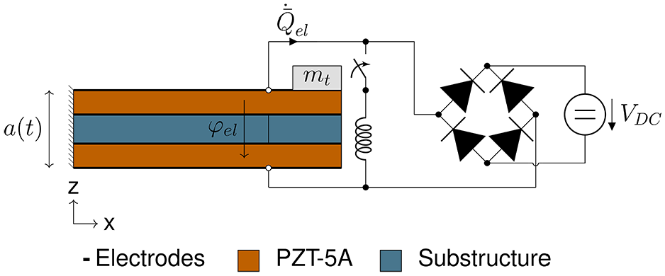
Bimorph PVEH with SSHI circuit.
Parameters of the bimorph electromechanical structure from Erturk and Inman (2009). Furthermore, the parameters of the SSHI circuit are listed.
Like in the previous chapter
In the simulation of the bimorph PVEH
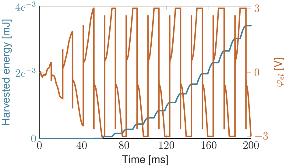
Firstly, a harmonic base excitation of
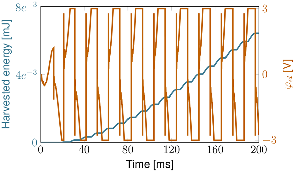
Harvested energy and
To analyze the influence of nonlinear elasticity on the behavior of the PVEH, simulations with the linear constitutive law are performed and compared to the results with the nonlinear constitutive law. Since the magnitude of the harmonic base excitation of
To further analyze the nonlinearities induced by the nonlinear elasticity model, a higher harmonic base acceleration of
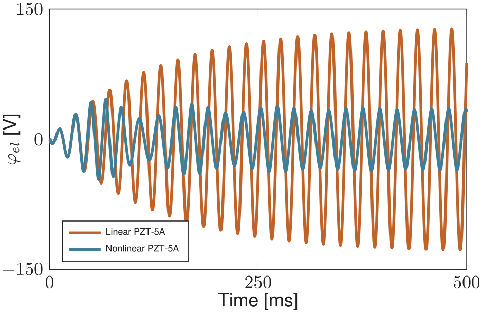
Comparison of
Figure 17 presents the comparison of the electric voltage
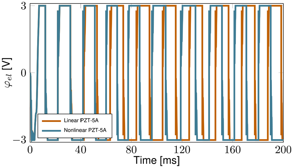
Comparison of
Figure 18 compares the harvested energy of the PVEH with nonlinear constitutive law with the harvested energy of the PVEH with linear constitutive law. A significantly reduced amount of energy is harvested by the nonlinear electromechanical structure. In this application example the nonlinear configuration harvests within
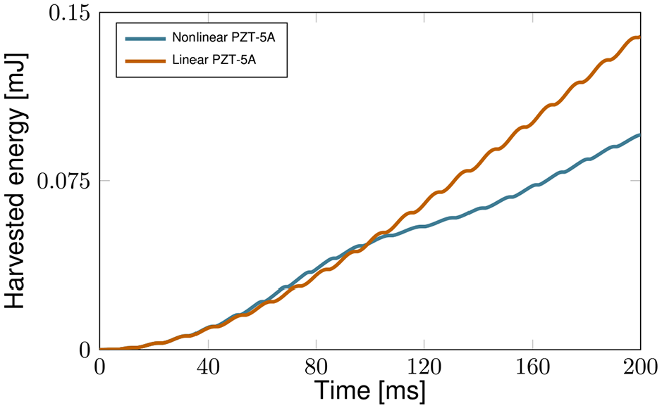
Harvested energy of the bimorph PVEH with nonlinear electromechanical structure respective linear electromechanical structure under a harmonic base acceleration of
In this contribution a DC battery, which is held at constant 1.8 V, is charged by the standard and SSHI circuit. Another important aspect would be to use different electric circuits to charge a storage capacitor instead of a battery (Zhang et al., 2021). We will apply the presented simulation framework in a future work to simulate the influence of a storage capacitor on the efficiency of PVEHs.
6. Conclusion
A novel finite element based system simulation approach for nonlinear electromechanical structures coupled to nonlinear electric circuits was introduced. The proposed solution scheme allows for arbitrary nonlinear effects, for example due to the material model, due to damping or due to the electric circuit. Using the Newton-Raphson method these nonlinearities are taken into account in a consistent manner. However, here nonlinearities are restricted to the material model and the electric circuit.
The presented system simulation approach is verified against an unimorph PVEH with an SSHI circuit from literature. The FE-based system simulation approach allows to couple the same unimorph PVEH to a standard circuit, confirming the higher efficiency of the SSHI circuit to harvest energy. Moreover, the tip displacement and electric voltage of the unimorph structure with open circuit configuration and an SSDI configuration is compared. The simulation results demonstrate that the proposed simulation method takes all coupling effects between the mechanical and the electrical domain into account. A further application example of a bimorph PVEH reveals the advantage of the presented system simulation method to easily account for nonlinearities in the electromechanical structure. The bimorph PVEH with SSHI circuit is simulated at a high excitation level. Nonlinear elasticity is considered in the material model of the piezoceramic representing the main source of nonlinearity in energy harvesting applications. Comparisons of simulations with linear and nonlinear material behavior of the piezoceramic demonstrate that significantly less energy is harvested when the nonlinear behavior of the piezoceramic is taken into account. Thus, accounting for nonlinearities of the electromechanical structure when the generated energy has to be computed is paramount for high levels of mechanical excitation.
The presented holistic simulation approach necessitates no external circuit simulation software and allows for efficient time integration schemes of the underlying differential equations. While exploiting the structural simulation capabilities of FEM without restrictions, the proposed method is highly flexible regarding changes of the electromechanical structure or of the electric circuit. The presented approach allows to evaluate both mechanical and electrical quantities in detail and facilitates the rapid development of PVEHs.
Footnotes
A. Appendix
Acknowledgements
The authors gratefully acknowledge financial support for this work by the Deutsche Forschungsgemeinschaft under GRK2495/C.
Declaration of conflicting interests
The authors declared no potential conflicts of interest with respect to the research, authorship, and/or publication of this article.
Funding
The authors disclosed receipt of the following financial support for the research, authorship, and/or publication of this article: This work was supported by the Deutsche Forschungsgemeinschaft under GRK2495/C [grant number 399073171].