
Abstract
Silicon-anode based lithium-ion batteries can provide large actuation strain and actuator strain energy through their novel electrochemical actuation mechanism. Battery actuators have strong potential as multifunctional actuators due to their ability to store energy, actuate, and self-sense. This paper presents a generic multilayer model that can predict the following actuator metrics for a multimorph: free deflection, blocked deflection, blocked force, actuator force, and actuator strain energy. Two case studies are explored including an experimentally validated case study with a 13-layer multimorph and a 33-layer multimorph. These case studies are investigated for a range of coating layer thicknesses and for two prevailing assumptions. The first assumes perfect bonding of all layers within the multimorph, and the second is a novel method where some layer interfaces in a multimorph are assumed be in slip. Results under the perfect bonding assumption indicate that the stiffer 33-layer performs better than the 13-layer in blocked force and actuator strain energy per active material volume. The 13-layer multimorph performs better in free deflection due to its larger compliance. When some layers are assumed to slip, the free and blocked deflection increase, due to the increased compliance, relative to all the perfectly bonded case studies.
1. Introduction
The demand for multifunctional and customizable smart actuators is growing in the field of smart devices. Multilayer actuators are likewise a field of growing interest. Multiple active layers are needed to maintain low actuation voltages in piezoelectric and electroactive polymer (EAP) actuators (Ahmed et al., 2017; Chin et al., 2006; Crawley and Anderson, 1990). Recently developed actuators that take advantage of the volume change associated with lithiation of silicon anodes (Ma et al., 2020; Shan et al., 2021; Xia et al., 2019) also need multiple layers to increase energy storage capacity. This paper focuses on the development of an analytical model for the prediction of useful actuator metrics for a multimorph. Specific contributions of this paper include introducing a model with generality of
A multimorph is defined here as the full class of multilayer beam-like structures with an arbitrary number of active and passive layers which is used for actuation and sensing. Subsets of multimorphs include unimorphs (single active layer) and bimorphs (double active layers), usually allowing for bi-directional actuation (Shan et al., 2021). Each layer is comprised of a uniform, isotropic material that may be segmented in length with varying width, thickness, and induced actuation strain.
The predicted actuator metrics for a multimorph include free deflection, blocked force (the force necessary to achieve zero tip deflection), blocked deflection (the resulting deflection along the length from the blocked force applied at the tip), actuator force for nonzero prescribed tip displacements, and actuator strain energy.
Timoshenko’s (1925) classic work derives closed-form expression for the deflection of single and double clamped thermal bimorphs. Weinberg (1999) derives the deflection of thermal, piezoelectric, and shape-memory alloy (SMA) multimorphs. DeVoe and Pisano (1997) present a model to predict the static behavior of piezoelectric multimorphs (multilayer unimorphs).
A similar analytical model is presented by Pal and Xie (2012), again for free deflection of a thermally actuated multimorph. They perform experimental validation for a unimorph with an embedded tungsten resistor (Pal and Xie, 2011). Their work modeled both the transverse deflection and twisting of a curved multimorph (unimorph).
Seminal thesis work for modeling of piezoceramic unimorph actuator deflections and dynamic analyzes is conducted by Wang (1998). Much work has also been done on unimorph and bimorph configurations of electroactive polymers (Ahmed et al., 2017; Frecker and Aguilera, 2004; Zhang et al., 2017) and piezoelectric ceramic materials (Cappelleri et al., 2002; Crawley and Anderson, 1990; Low and Guo, 1995; Robbins and Reddy, 1991; Vel and Batra, 2001). An advantage lithium-ion batteries (LIBs) share with ceramic piezoelectrics and electroactive polymers (EAP) is the reduced operating voltages that result from stacking thin active layers (Crawley and Anderson, 1990; Low and Guo, 1995).
Previous work with multilayer, multifield actuation is conducted by Erol et al. (2020). They investigate the multi-objective optimization of the actuated shape of a segmented, multilayer, and multi-field actuator. However, they focus on free deflection and do not consider other actuator metrics which are addressed in this paper (e.g. blocked force, blocked deflection, actuator force, and actuator strain energy).
The model presented in this paper uses a novel electrochemical-based actuation mechanism due to its multifunctionality and advantages over other actuation mechanisms. These advantages include simultaneous energy storage, self-sensing, and actuation (Goodenough and Park, 2013; Sethuraman et al., 2010; Xia et al., 2019). The multifunctionality of silicon-anode based lithium-ion batteries and their promise as actuators drive the development of analytical models because self-sensing, actuating, energy storing actuators have the components necessary to be self-contained, after an initial charging.
LIB actuators have the advantage of being self-contained and self-powered. They do not require continuous external power input, like other actuation mechanisms do (e.g. electroactive, magnetoactive, pneumatic, etc.). Electroactive materials require an externally applied electric field (Pelrine et al., 2000); magnetoactive materials require a magnetic field (Erol et al., 2020); soft pneumatic actuators (SPAs) require pumps and tubes (Huang et al., 2020); and liquid crystalline elastomers require stimulation by temperature, light, or electric fields (Ohm et al., 2010). This ability to not require continuous external input, but to also power an external load, makes energy storage based actuators strong candidates for mobile applications and applications with minimal accessibility. Relevant application spaces for LIB actuators include minimally invasive surgical tooltips (MIS) and active mobile robotics applications. LIB actuators are suitable for applications that require portability and that are hindered by excess cables. This self-containment and the ability to be tailored to individual applications necessitate models that allow for the prediction of actuator metrics for widely applicable multilayer geometries.
Cannarella et al. (2014) investigate the stress-potential coupling of silicon, which is then harnessed in self-sensing experiments conducted by Ma et al. (2020). Xia et al. (2019) showcase silicon anode-based lithium-ion batteries as a reconfigurable material through both simulation and experiment. Chin et al. (2006) show the effectiveness of graphite-anode based lithium-ion batteries as actuators. Though, graphite proves to generate a poorer actuation strain than silicon due to its smaller volumetric expansion of 13.1% compared to silicon’s over 300% (Baranchugov et al., 2007; Chin et al., 2006).
Ma et al. (2017) model the free deflection of a silicon anode based unimorph. This model is further developed by the authors for predicting the free deflection (Gonzalez et al., 2018), as well as blocked force and blocked deflection of segmented unimorphs (Gonzalez et al., 2019, 2021). The model is then extended into a bimorph configuration to predict free deflection of a segmented bimorph (Gonzalez et al., 2020).
This paper contributes an analytical model that can predict actuator metrics for a wide array of multilayer actuators of varying geometries and actuation mechanisms. The previous derived perfect bonding model (Gonzalez et al., 2021) is compared with a model that allows slip between layers. The model predictions for two representative multimorphs are compared with experimental results.
2. Methods
Models of unimorph (Gonzalez et al., 2021) and bimorph (Gonzalez et al., 2020) LIBs have been published previously by the authors and are reviewed briefly here. A schematic for an
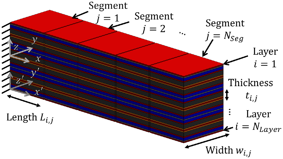
Schematic for an
The equations of equilibrium of a multimorph are solved to obtain the free curvature and axial strain at the neutral axis. All layers are assumed to be perfectly bonded such that a strain mismatch developed between active and passive layers drives actuation.
In the current paper, previous models are extended to account for multimorph configurations of any number of layers and segments for both perfectly bonded multimorphs, and multimorphs where some layers slip. Slip in this case means that there is no interlayer friction, and that the respective layers can slip freely. Slip cases or interfacial slip cases are defined to be those cases that assume some specified interfaces are in slip. This approximation is developed to predict the behavior of actuators with interfaces in slip. These slip cases are investigated to better understand the actuator metrics when layers are not bonded to each other as in multilayer battery actuators.
2.1. Analytical model
The analytical unimorph model derived primarily in prior work (Gonzalez et al., 2021), is discussed in brief here. The actuation strain
The linear strain constant or expansion coefficient
The average, normalized lithium concentration
2.1.1. Assumptions
To execute the analytical models discussed, each element of the beam is considered to be in quasistatic equilibrium due to the relatively quick propagation of lithium into silicon (∼0.4 h for particles in the tens of nanometer diameter range) compared to the rates at which the battery is charged (20 h) (Gonzalez et al., 2021). In dynamic cycling of the battery actuator, the reaction kinetics and diffusion dynamics play a role in the displacement response. Actuation is directly linked to Si expansion with Li insertion, so the reaction kinetics of the anode contribute significantly to the overall system time constants. However, it is assumed that the experimental results are sufficiently slow to compare with the theoretical quasistatic results.
Small deflections are assumed for blocked force calculations. The length of the multimorph is assumed to be at least an order of magnitude greater than its width and thickness such that actuation is assumed to only occur in the longitudinal direction. The variation in width of the layers is accounted for when calculating the equivalent stiffness; however, the origin of the global coordinate system lies at the base of the beam (x-axis), the side of the anode (y-axis), and the bottom of the bottom (
The bending moment due to self-weight is considered negligible relative to the bending moment due to induced actuation. For the perfectly bonded case, there is no slip at all interfaces. For the slip case, slip is assumed to occur only on the interlayer separators.
2.1.2. Equations of equilibrium
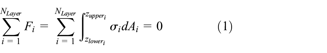
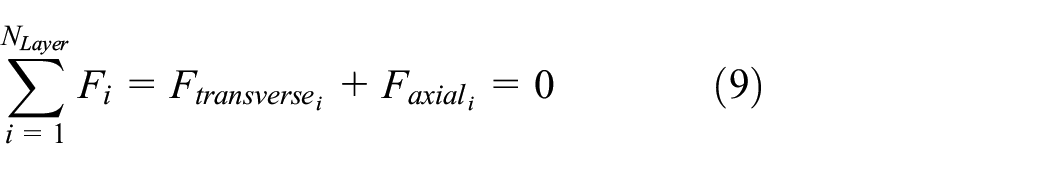
To find the free curvature of a multilayer cantilever multimorph, the equations of equilibrium must be solved. The sum of forces
Figure 2 shows a cross-sectional diagram of the
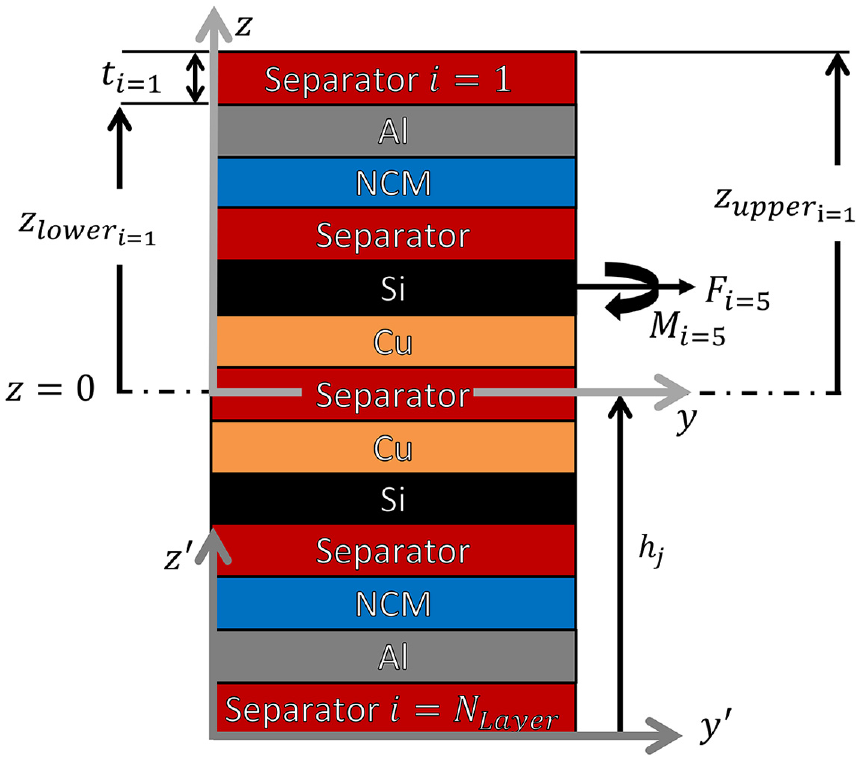
Multilayer cross-section.
The induced stress of the

where,

The limits of integration in equations (1) and (2) are defined in equation (4). These limits are the respective positions of the upper and lower geometric location of the
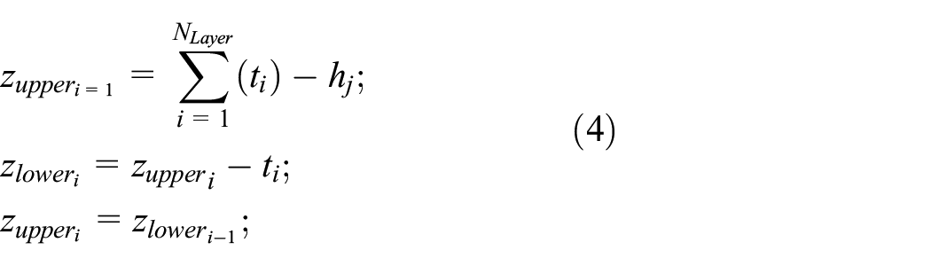
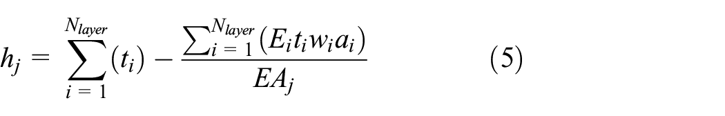
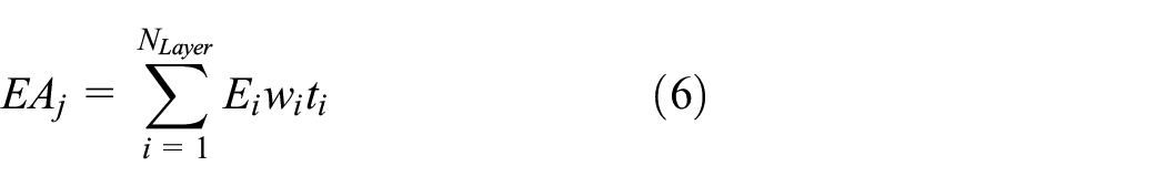
The constants
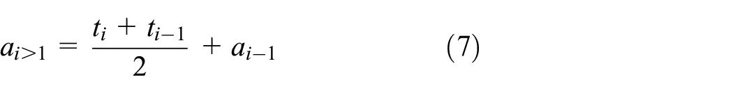
where,

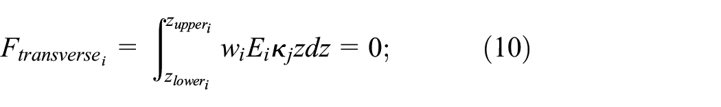
Equation (1) can be rewritten as the sum of the forces due to the transverse and axial loading of each
The axial or longitudinal forces can be solved to find the axial strain at a reference axis
The transverse force naturally sums to zero for an actuator based on increasing internal actuation strain.
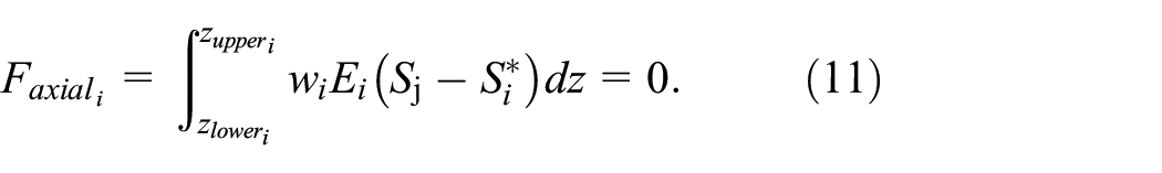
Equation (11) can be evaluated, the integral solved, and the results rearranged to find equation (12).
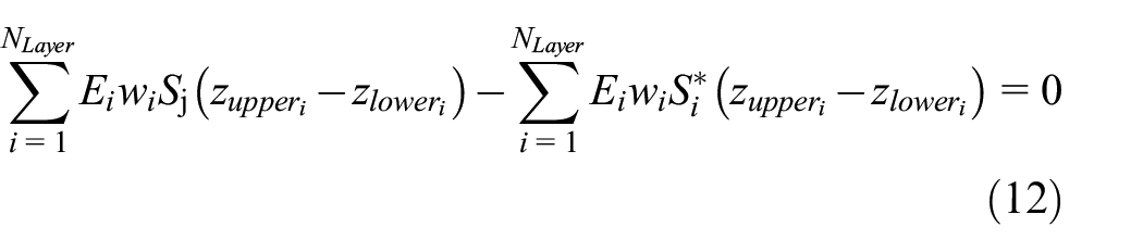
The terms accompanying
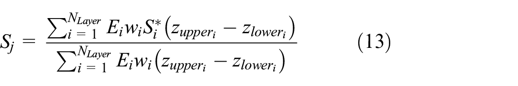
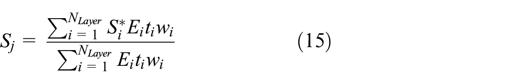
The difference in the upper and lower limits of the

Equation (14) can be substituted into equation (13) to get the simplified expression for axial strain at the neutral axis for the
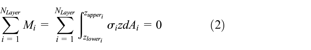
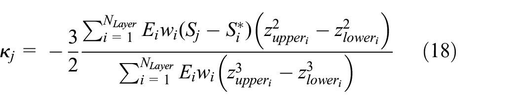
The sum of moments in equation (2) can be expanded by substituting equation (3) to get equation (16). The integral can be solved and the term including the free curvature can be subtracted from the right-hand side of the equation as shown in equation (17).
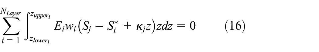
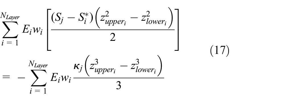
The free curvature of a multilayer can then be found by dividing the left-hand side of equation by the right-hand side variables to isolate free curvature. This can be further simplified to get the free curvature of the
2.1.3. Strain throughout the multilayer
The strain

2.1.4. Actuator metrics
2.1.4.1. Free and blocked deflection
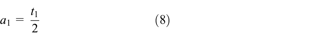
The authors have previously reported the derivation of the actuator metrics here for a unimorph and the free deflection of a bimorph (Gonzalez et al., 2020, 2021). The free deflection and blocked deflection are found by taking the free curvature
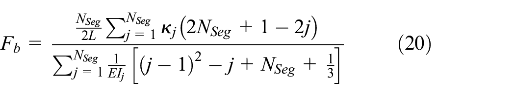
2.1.4.2. Blocked force
The blocked force of a segmented multimorph is shown in equation (20) and is further generalized from previous work (Gonzalez et al., 2021) where
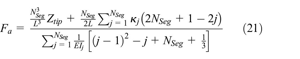
2.1.4.3 Actuator force and actuator strain energy
The actuator force
2.2. Slip cases
Slip is mathematically defined such that slip occurs in one displacement coordinate direction only. The axial or longitudinal

where
For the example shown in Figure 3, the slip between the top and middle layer is denoted
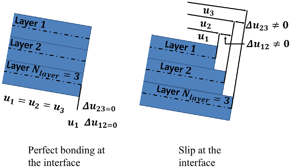
Schematic showing effect of perfect bonding and slip at the interface of active (top) and passive (bottom) layers.
An equivalent passive layer is used to approximate layers with interfaces in slip as shown in Figure 4(a). Equivalent passive layer is defined here to mean a single passive layer that is sandwiched between two active layers. This equivalent passive layer is used to approximate the combined bending stiffness of all the individual passive layers of the multimorph being analyzed. It is comprised of the following layers (NCM and Al, Separator, and Cu). The NCM and Al are considered together because they are assumed to be perfectly bonded. Perfectly bonded layers add bending stiffness. This added bending stiffness must be reflected in the equivalent bending stiffness of the equivalent passive layer. The total thickness of the equivalent passive layer
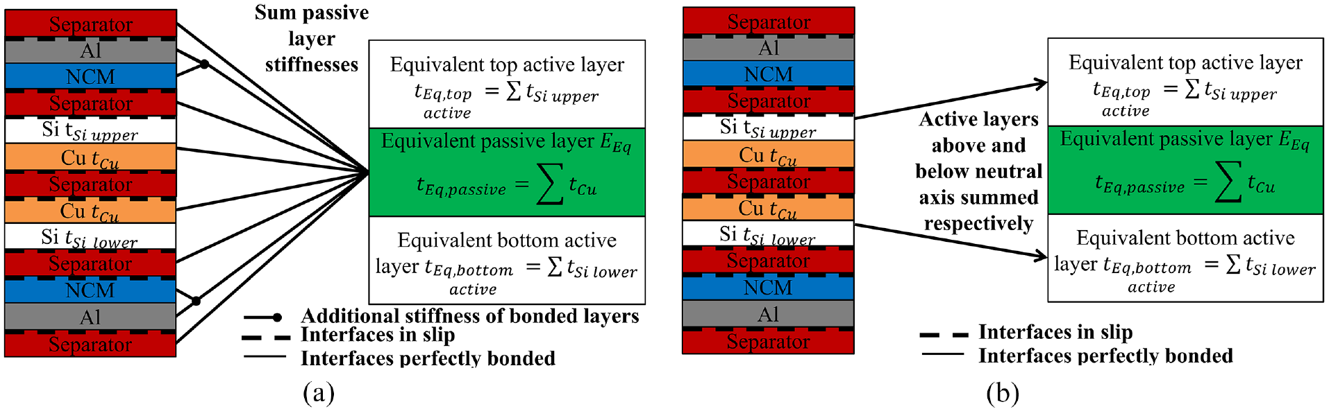
(a) Schematic of equivalent passive layer (e.g. 13-layer bimorph (passive layers in color) and (b) Schematic of equivalent top and bottom active layers (active layers in white).
Although the elastic modulus of the Si coating layer is assumed to be the same for simplicity, the thickness of equivalent top active layer
Thus, a 3-layer bimorph that consists of an equivalent passive layer, sandwiched by and perfectly bonded to two equivalent active layers can be used to approximate interfacial slip between specified layers of an
The elastic modulus,
If interfacial slip is assumed between all layers,

This equivalent elastic modulus
2.3 Interfacial slip approximation
Two case studies are considered, a 13-layer and a 33-layer multimorph as examples of batteries that are comprised of multiple individual cells. These two configurations are shown in Figure 5. The 13-layer is studied because it is composed of two complete Li-ion battery cells (one top and one bottom). The 33-layer is investigated because it is composed of six Li-ion battery cells. Both studies are investigated for when interfacial slipping at the separator interfaces is allowed (slip), and for when interfacial slip is not allowed (perfect bond between all layers). All case studies consider a single segment,
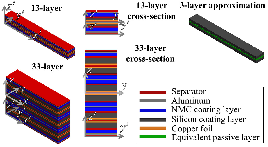
Schematic of the 3-layer approximation of both the 13-layer and 33-layer case studies (not to scale).
For the LIB studied, both electrodes are assumed to consist of perfectly bonded coating and metal current collector. The two electrodes are a positive electrode (cathode) comprised of an NMC (Nickel Manganese Cobalt Oxide) coating on an aluminum current collector, and a negative electrode (anode) comprised of a composite silicon coating coated on a copper foil current collector. The coated current collectors are separated by a plastic separator that prevents short-circuiting between electrodes. The interfaces of the separator are assumed to be in slip with all other layers. As seen in the 13-layer case study shown in Figure 5, five of the separator layers separate two unimorph anodes and two passive cathodes.
The two outer separators outside the cathodes simulate the packaging material. The 13-layer case study shown in Figure 5 is comprised of several layers of 3.5 cm length
The thicknesses of layers are the separator of
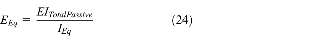
Equations (24)–(26) are applied to a 13-layer bimorph. Equation (24) is used to find the effective elastic modulus of the equivalent 3-layer bimorph that is necessary to achieve the same bending stiffness as all the passive layers combined. This includes the increased bending stiffness of the cathode due to the shifting of the neutral axis from the perfect bonding assumption between coating and current collector. Equation (25) is used to find the area moment of inertia for an equivalent passive layer where
The bending stiffnesses of the passive layers—five separators, two perfectly bonded cathodes (with Al and NCM layers), and two passive copper foil layers—are summed as in equation (26) to get
Also shown in Figure 5 is the schematic for a 33-layer bimorph along with an example 3-layer approximation. The approximation holds, though the thicknesses must change. The equivalent 3-layer bimorph for the 33-layer sums up the thickness of all the copper foil current collectors (6 layers,
Using the perfect bonding assumption, all the active layers above the neutral axis in the 33-layer are activated and held at a nonzero state of charge to achieve transverse deflection downward. Mathematically this equates to
2.4. 13-layer experimental validation case study with perfect bonding
First, we analyze the 13-layer example shown in Figure 5, where all layers are assumed to be perfectly bonded. The 13-layer is arrayed in such a manner that the central bimorph is effectively split into two unimorphs by a plastic separator, as seen in Figure 5, to allow for practical control of each complete battery cell independently in experiment.
The thickness of layers are the separator of
The experimental setup, adapted from work by Shan et al. (2021), is shown in Figure 6. The tip displacement of the 13-layer multimorph is captured every 3-minutes by macro-lens digital camera and then analyzed to obtain the deflection data using image processing software.
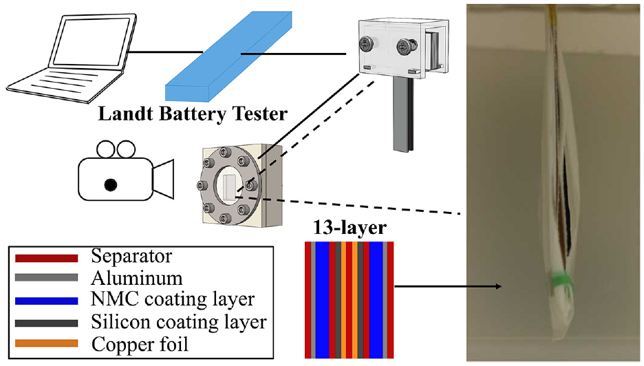
Experimental setup.
As seen in Figure 6, the thirteen layers are not perfectly parallel, and the exterior separators bulge out. Due to fabrication limitations, the actuator twists and the tip displacement, which is tracked by the green tape, has some inherent error that shows up in the range of longitudinal tip displacement. Notably, the N/P ratio of this experimental validation 13-layer case study is 0.956 to ensure there is adequate lithium hosting capacity in the cathode to fully charge the anode. As a result,
2.5. 13-layer experimental validation case study with interfacial slip
The relationship between
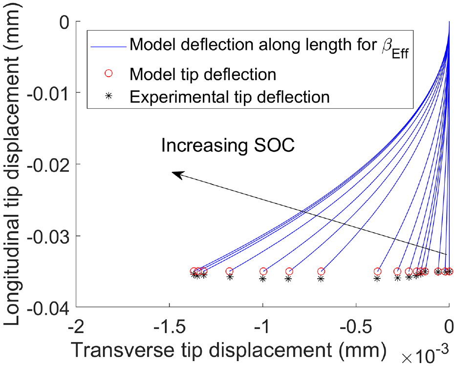
Experimental validation for a 13-layer multilayer split unimorph case study with perfect bonding assumption.
The variation of
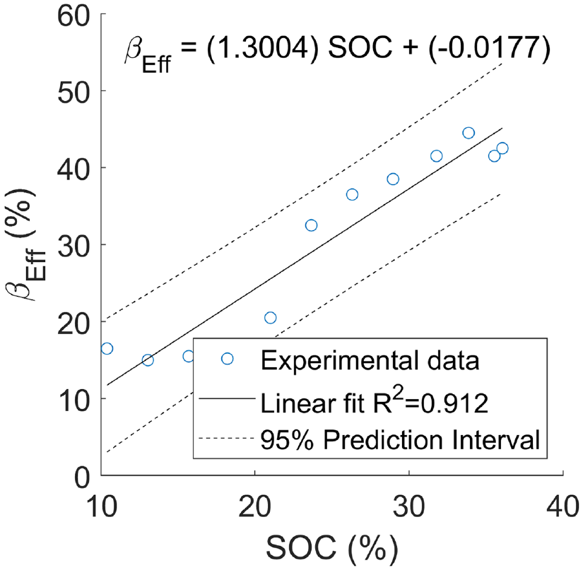
An experimentally validated
The linear fit shown in Figure 8 is
If we assume slip at the separator interfaces, then the predicted tip deflections are much larger for a given
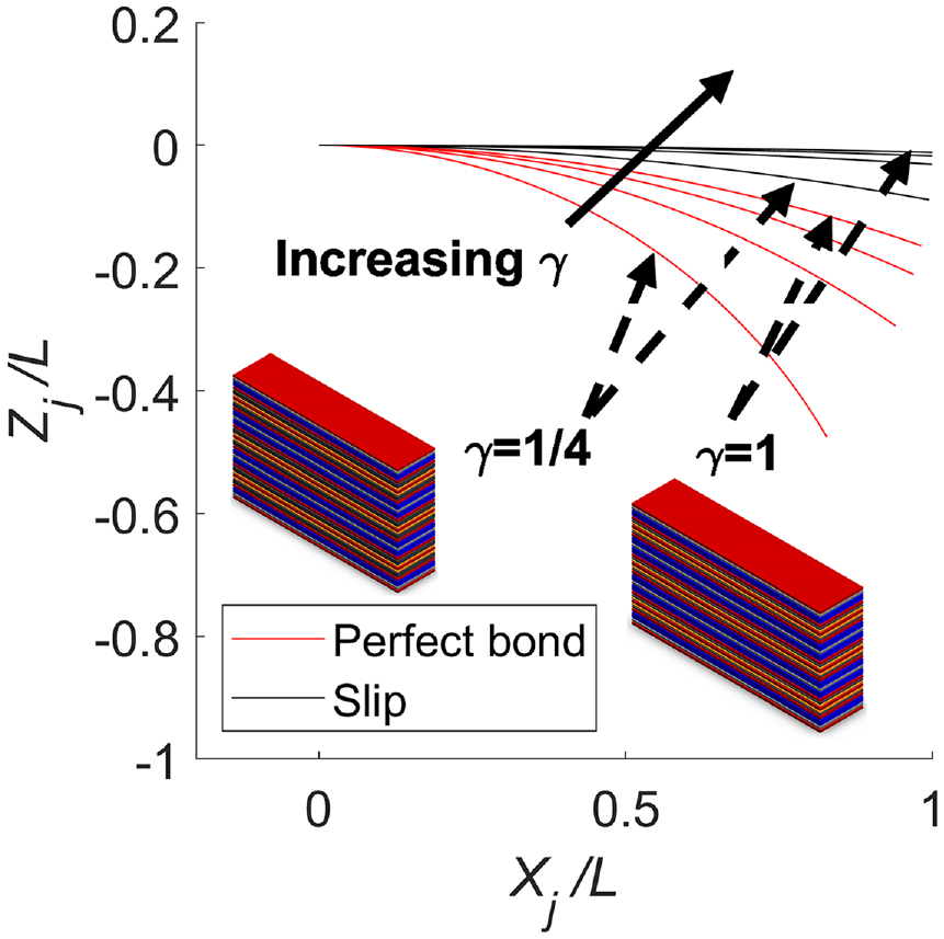
The 13-layer case study shown in Figure 5 is further explored for a range of coating layer thickness variables. All other parameters remain the same. This is reflected in the schematics embedded in Figure 9. The thickness of the silicon coating layer variable ranges from
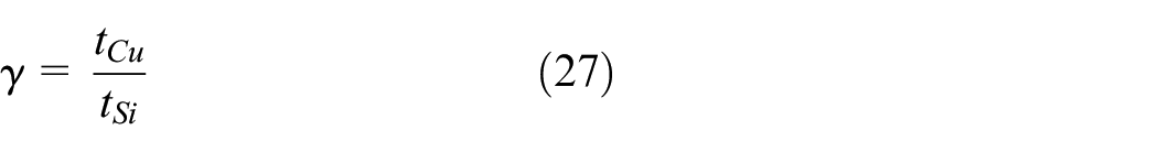
as the ratio of Cu to Si thickness. The maximum free deflection for a 13-layer multilayer multimorph is shown in Figure 9. The ratio
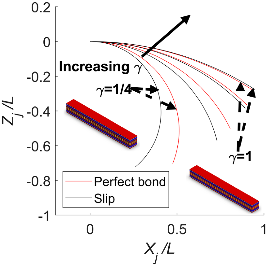
Normalized longitudinal free deflection versus normalized transverse free deflection for a 13-layer multimorph cantilever.
2.6. 33-layer theoretical case study
The 33-layer case study (schematic shown in Figure 5 and embedded in the Figure 9 and Figure 14) is comprised of several layers of 3.5 cm length
The thickness of layers are the separator of
3. Results and discussion
A 13-layer case study is investigated and experimentally validated both when all layers are assumed to be perfectly bonded and when some layers are assumed to slip at the interface. Similarly, a 33-layer theoretical case study is shown to demonstrate the benefits of a LIB actuator with more Li-ion cells (6 cells) than the 2-cell, 13-layer configuration.
3.1. 13-layer case study for range of coating thickness
The 13-layer case study under the interfacial slip assumption shows larger maximum free deflection than the 13-layer under the perfect bonding assumption. For nearly two orders of magnitude less actuation strain based on the
The larger compliance of the 13-layer with interfacial slip compared to the perfect bonding assumption can be seen in the blocked deflection results in Figure 10. Whereas the 13-layer case study achieves a maximum transverse blocked deflection of over 3 mm, the perfectly bonded beam achieves only about 2.5 mm.
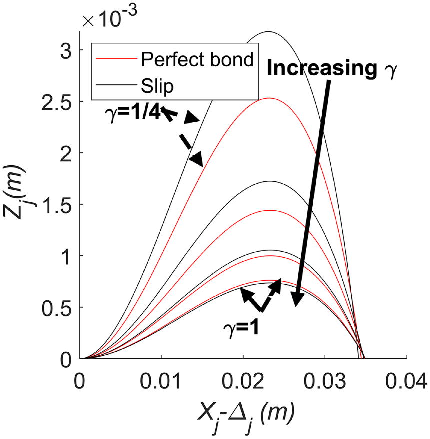
Normalized longitudinal curvature shortening versus normalized transverse blocked deflection for a 13-layer multimorph.
The comparatively large bending stiffness of the perfectly bonded case shows in Figure 11, in the higher blocked force per active material volume for all ratios of
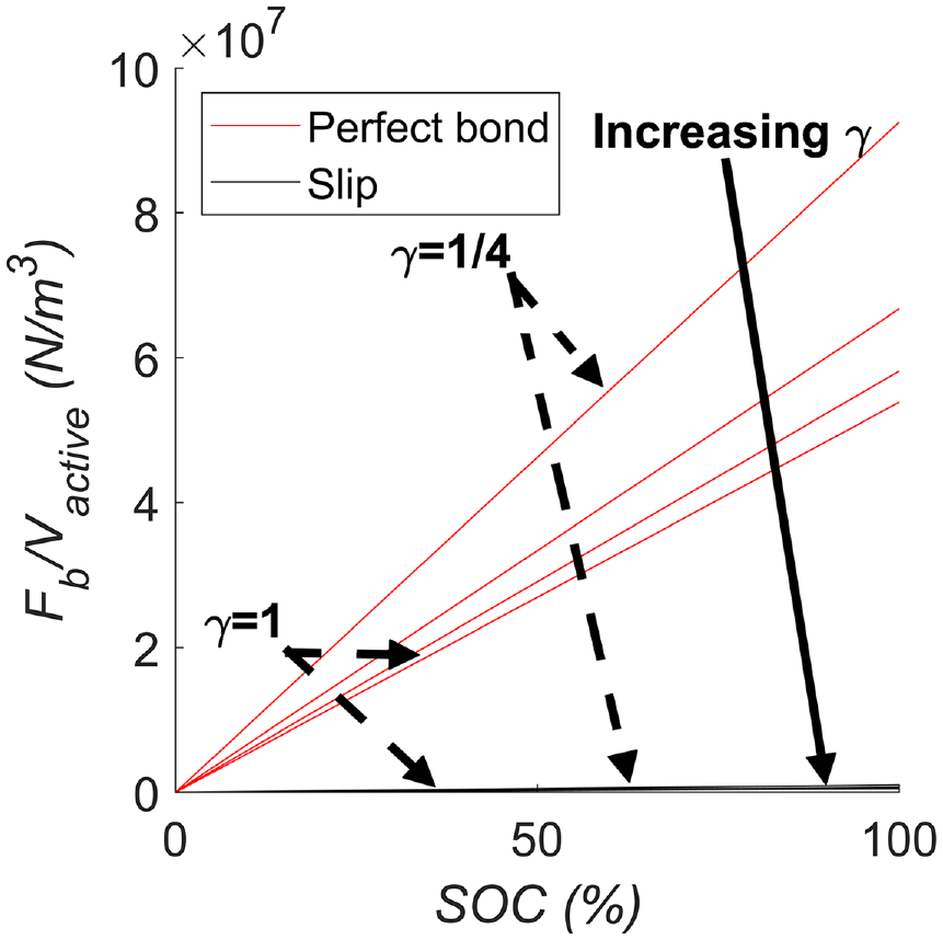
Blocked force normalized by active material volume versus SOC for a 13-layer multimorph. The values for slip lie on the x-axis and are approximately zero for all abscissa values.
Both the blocked force (y-intercept) and the free deflection (x-intercept) are shown in Figure 12 where the actuator force normalized by volume of active material is plotted against the prescribed tip displacement. The area under the curve is the actuator strain energy, and the case with the most area under the curve is the perfectly bonded case for
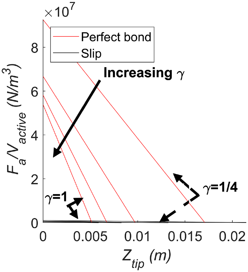
Actuator force normalized by active material volume versus prescribed tip displacement for a 13-layer multimorph. The values for slip lie on the x-axis and are approximately zero for all abscissa values.
Figure 13 shows that even with eightfold more active material, the normalized actuator strain energy still increases exponentially as the
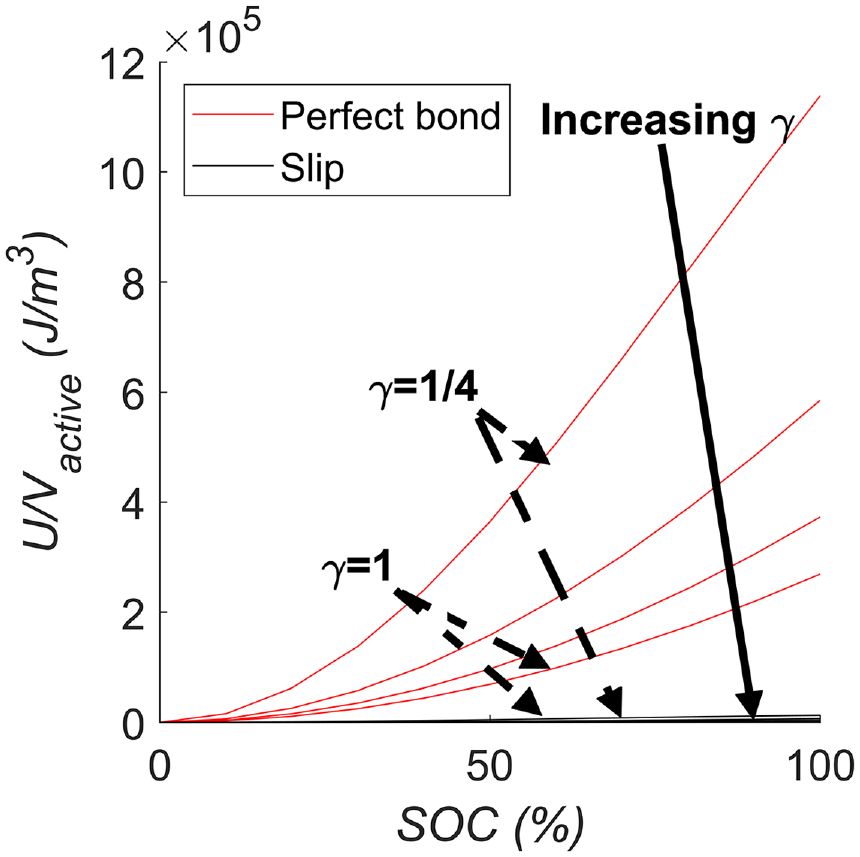
Actuator strain energy normalized by active material volume versus SOC for a 13-layer multimorph. The values for slip lie on the x-axis and are approximately zero for all abscissa values.
3.2. 33-layer case study for range of coating thickness
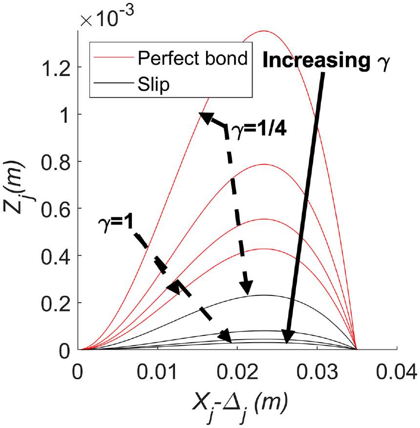
The free deflection for a 33-layer multimorph is shown in Figure 14 for
Normalized longitudinal free deflection versus normalized transverse free deflection for a 33-layer multimorph.
The actuation strain for the perfectly bonded and slip cases are
Figure 15 shows the blocked deflection for a 33-layer multimorph. As in Figure 14, what should be the larger compliance of the slip case, is overcome by the increased actuation strain of the perfectly bonded case and the increased equivalent elastic modulus of the slip case. The maximum blocked deflection is less than 10% of the length at less than 0.2 mm for the
Normalized longitudinal curvature shortening versus normalized transverse blocked deflection for a 33-layer multimorph.
The effect of the much larger actuation strain and bending stiffness of the perfectly bonded case is evident in Figure 16. Of note is that, although the total thickness of the summed coating layers is increased by twenty-four times (compared to
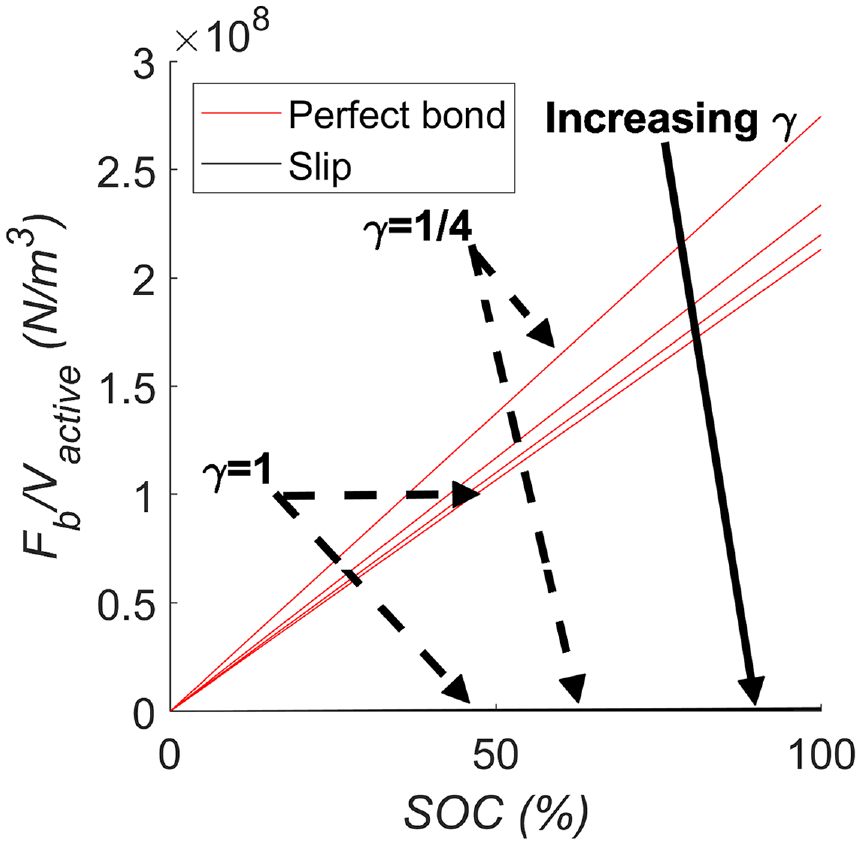
Blocked force normalized by active material volume versus state of charge (SOC) for a 33-layer multimorph. The values for slip lie on the x-axis and are approximately zero for all abscissa values.
The largest blocked force normalized per volume of active material is over
Figure 17 shows the actuator force normalized by active material for prescribed tip displacement. The perfectly bonded 33-layer case achieves a large blocked force (y-intercept) and large free deflection (x-intercept) (both relative to the slip case) and has a relatively large area under the curve (actuator strain energy) relative to the comparatively negligible slip case. There is some inaccuracy of the predicted actuator force (due to the small deflection assumption inherent in Castigliano’s theorem) for large free deflection, but the difference in actuator force per volume for the bonded case and the slip case is so large, the inaccuracy is assumed negligible.
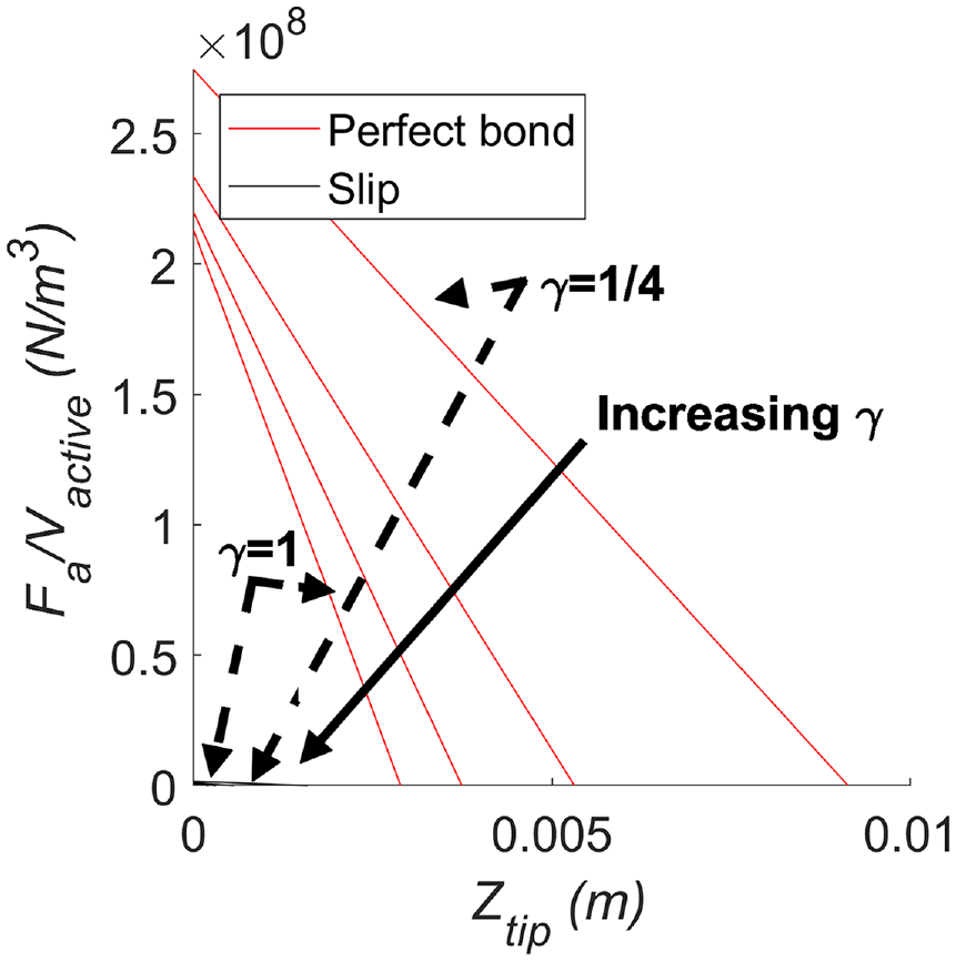
Actuator force normalized by active material volume versus prescribed tip displacement for a 33-layer multimorph. The values for slip lie on the x-axis and are approximately zero for all abscissa values.
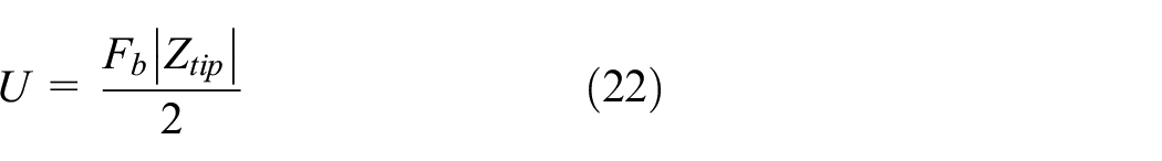
The actuator strain energy is predicted as the product of half the blocked force and free deflection (equation (22)) as is shown in Figure 18. The actuator strain energy for the 33-layer case study in slip maxes out at approximately
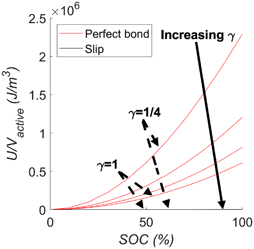
Actuator strain energy normalized by active material volume versus SOC for a 33-layer multimorph. The values for slip lie on the x-axis and are approximately zero for all abscissa values.
4. Summary and conclusions
An analytical model has been developed to predict the free deflection, blocked force, blocked deflection, actuator force, and actuator strain energy for an infinitely layered multimorph. An approximation for cases with interfacial slip has been developed in parallel. This approximation for interfacial slip between specified layers allows for prediction of the actuator metrics for a multilayer actuator. For both bonded and slip cases, an equivalent passive layer is sandwiched by two equivalent active layers to allow for bimorph actuation. The analytical model developed is experimentally tuned with a case study wherein the free deflection of a 13-layer multimorph is compared against its analytical model equivalent.
It is found that
Two case studies are investigated using the experimentally tuned model. The actuator metrics for both a 33-layer case study and a small parametric study of the 13-layer case are both shown for a range of coating layer thickness. It is found that the normalized actuator strain energy
It is found that the blocked force and actuator strain energy increases for increasing numbers and thicknesses of active layers despite normalization by volume of active material. More layers are more effective, as has been previously seen in multilayer piezoelectric actuators. For all cases investigated here, the normalized actuator continues to increase with more active layers despite the added bending stiffness from both the added active material, and the necessary passive materials for the battery to work (additional separators, cathodes, and copper foil). Many LIB actuators can be stacked to achieve more actuator strain energy than any one LIB actuator could achieve alone. Six stacked LIB actuators has substantially more actuator strain energy than two stacked actuators, and so it is possible to stack many more actuators to achieve even greater actuator strain energy.
A primary benefit of the electrical energy storage functionality of LIB actuators is the ability to store charge while also providing actuation. While using active Li-ion cells does complicate actuator design, the tradeoff is considered worthwhile for potential applications in the fields of minimally invasive surgery (MIS) and active rehabilitation aids. In MIS, surgical space is limited and reduction of wiring by introducing battery power stored in the actuator could be very beneficial. Likewise, actuation and energy storage can be decoupled by simultaneously charging the top and bottom electrode of a bimorph. Such Si-anode based LIB actuators can improve both battery capacity and actuator performance by coupling or decoupling actuation and energy storage depending on the application.
Some critical future implementation challenges for this work include development of a flexible pouch cell to allow for more movement of the battery actuator. Cycling remains a difficulty that may be well tackled by a flexible current collector to eliminate the plastic deformation of the metal current collectors. Delamination of the Si composite presents a challenge that may be tackled by an increase in binder percentage, a thinner active material layer, and a flexible pouch cell that maintains a pressure on the electrodes to prevent delamination.
Footnotes
Appendices
Declaration of conflicting interests
The authors declared no potential conflicts of interest with respect to the research, authorship, and/or publication of this article.
Funding
The authors disclosed receipt of the following financial support for the research, authorship, and/or publication of this article: The authors gratefully acknowledge the support of the National Science Foundation under Grant No. 1662055.