
Abstract
Tribological characterization was carried out in part 1 of the paper on pure PTFE (PTFE) and 25% carbon-filled PTFE (CR25) polymers through the ball-on-disc test to determine the suitability of the material for ball-bearing applications. This part focuses on fabricating and analysing CR25 and PTFE radial deep groove ball bearings for characteristics. An OR35-INST, a 6-channel DAQ system integrated with ORBI gate and NV-gate software, was used to record the vibration characteristics. Initially, a free run test was conducted, in which the shaft was supported on the fabricated PTFE/Carbon and PTFE polymer bearings and was rotated for two million cycles. Throughout the test, its RPM and vibrational amplitudes were continuously recorded. After one million cycles, the supported shaft’s dynamic characteristics (orbit and shaft centerline plots) were obtained. The free-run test results reveal that the shaft mounted on the bearing sets has excellent dynamic stability. Finally, a rolling contact fatigue test (RCF) was performed in which the fabricated polymer bearings were subjected to a variable radial load from 36 N to 108 N for one million cycles. The results show that the proposed PTFE composites can be used to develop ball bearings in low-load and RPM applications.
Introduction
Based on the characterization results in part 1 of the paper, it is worth assessing the suitability of CR25 and PTFE polymers by fabricating and analysing the bearings for characteristics. The testing of composites in the actual form of the product provides useful insight. In the bearing application, PTFE is used mainly in sliding or thrust bearings. 1 Further, it has replaced the Babbitt alloy coating on the thrust bearing pad because it offers a low friction coefficient during the interaction. This feature reduces the pad’s crowning and helps maintain a consistent oil thickness, resulting in a more uniform pressure distribution than metal coatings. Consequently, these enhancements lead to improved bearing performance and a reduction in size. 2 Limited studies are available on the use of polymer composite material usage for ball-bearing applications.3,4 However, some studies have explored the feasibility of polymer bearings with detailed characterization of the bearing through FTIR, XPS, and a confocal microscope to better understand bearing failure and its mechanism.5,6 In study, 7 the authors compared the performance of metal, PEEK, and 25% carbon-filled PTFE miniature bearings. The findings show that the carbon-filled PTFE bearing has better RPM stability than the PEEK bearing. Further, Koike et al. 8 fabricated PEEK ball bearings with alumina balls and a PEEK retainer. The bearings were fabricated through a rod on the lathe machine with an outer diameter of 52 mm, an inner diameter of 25 mm, and a retainer to hold the balls and alumina balls. The author calculated the load range in which the bearing can sustain a load of up to 1 million cycles for a particular RPM. The bearings that failed beyond the load range experienced bearing seizure due to frictional heat, which also caused the ball retainer to fail. However, the bearing performance was improved by replacing the PEEK retainer with 25% carbon-filled PTFE due to its self-lubricating properties.9–13 Furthermore, the authors have also compared the bearing performance of the hybrid PEEK bearing with that of the PPS hybrid bearing, and the finding shows that PEEK outperformed the PPS hybrid bearing. 14 Bearing design is crucial, and one of the key reasons for bearing failure is the heat generated by friction, which leads to the deformation of bearing parts. A well-designed bearing can effectively minimize frictional heat during operation and enhance its load-bearing capacity. Additionally, these frictional forces also diminish the efficiency of the bearing and reduce its load-bearing capacity. Therefore, it is necessary to improve the bearing design, particularly for the bearing cage. Further, very few articles are available on the vibrational characterization of the fabricated bearing is performed.
In industrial and maintenance areas, the analysis of vibration signals has been carried out over the many decades. Vibration signals help to detect misalignment, unbalance, and looseness in the system. 15 Hence, the vibration signal obtained during rotation can be a key factor in checking the bearing feasibility. In the past, conventional bearings, such as metal, 16 hydrostatic, 17 hydrodynamic 18 etc., have been used to support both low as well as medium-speed rotors, whereas non-contact bearings, such as foil 19 and magnetic bearings 20 have been used to support high-speed rotors. Along with these, dynamic analysis of the rotor is considered a preventative technique for fault-free operations by monitoring the shaft behaviour. 21 Intensive research has been carried out in the field of metal/alloy-based ball bearings, and they are still widely accepted in ball-bearing applications. These metal bearings require external lubrication for smooth operation, and they are not resistant to corrosion. To overcome these issues, polymer bearings have emerged as a replacement for metal bearings where providing lubrication and working conditions are challenging.22,23
In this paper, CR25 and PTFE deep groove ball bearings (DGB) were fabricated, and Si3N4 balls were used as rotating elements to check their suitability in the DGB applications. The Si3N4 has high crushing strength, which provides strength to the bearing, and its non-corrosive nature makes the bearing corrosion resistant. The vibration signals of the shaft supported by the fabricated bearings were examined. Additionally, the performance of CR25 bearings was evaluated in comparison to PTFE bearings featuring Si3N4 balls to assess the impact of reinforcement on bearing performance. The fabricated bearings were employed to support the shaft, which was rotated for 2 million cycles. The shaft’s vibration characteristics and speed were continuously recorded on a computer using the OR35-INST, a 6-channel DAQ system, along with eddy current probes to capture the dynamic properties of the rotor. Ultimately, the load-carrying capacity of the bearings was assessed using an RCF machine that was developed in-house to measure the vibration signals. The load and RPM used in the RCF test are similar to the testing parameters provided in part 1 of the paper (load: 25-75 N and speed: 800 RPM). The procedure followed to check the usage of the fabricated bearings is shown in Figure 1. Overview of the procedure followed to check the usage of the fabricated bearings.
Material and fabrication
Mass loss in bearings in the free-run test.

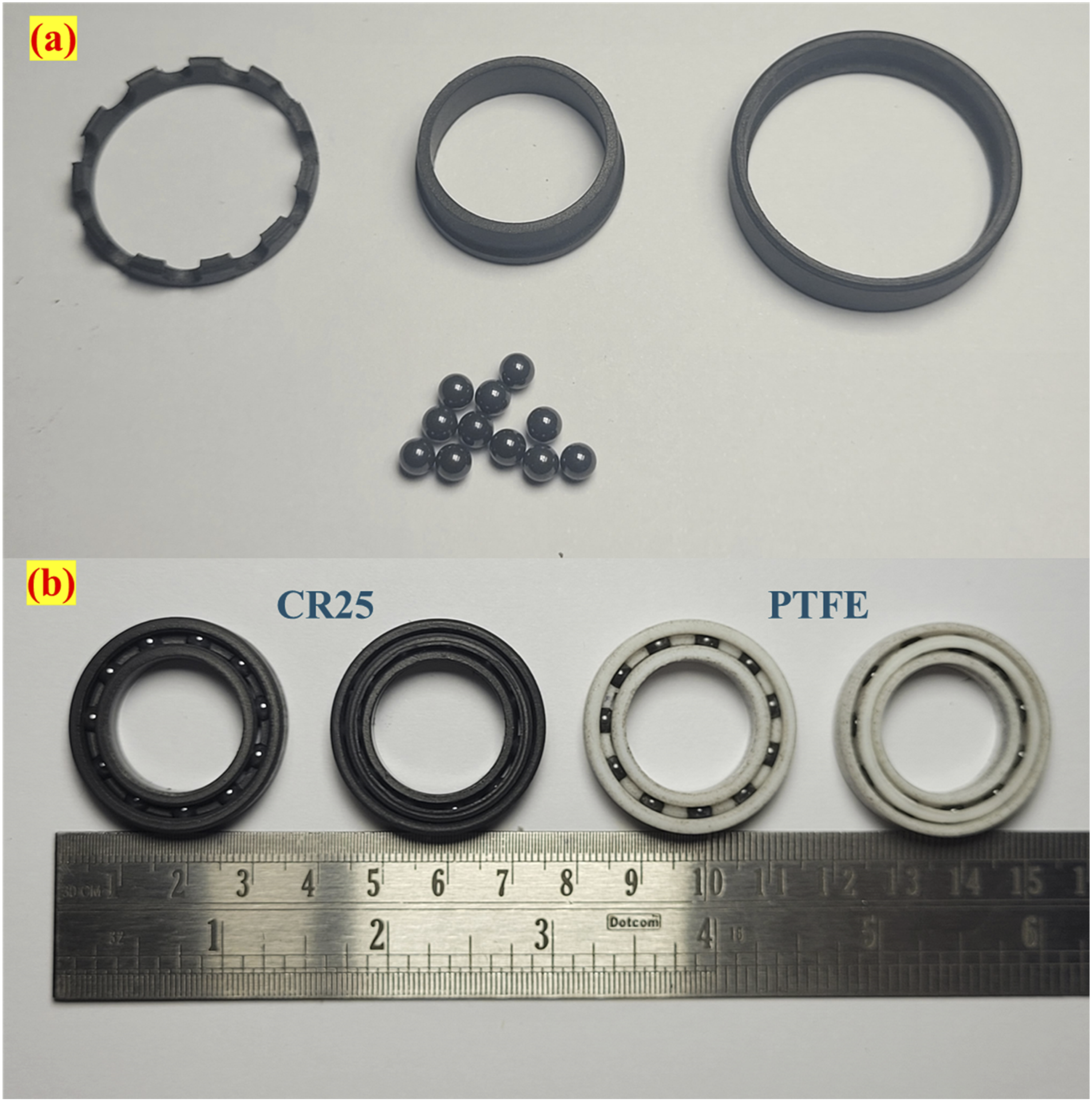
(a) Parts of the fabricated CR25 bearing with Si3N4 balls (b) assembled PTFE and CR25 bearings.
Testing procedure
Free-run test
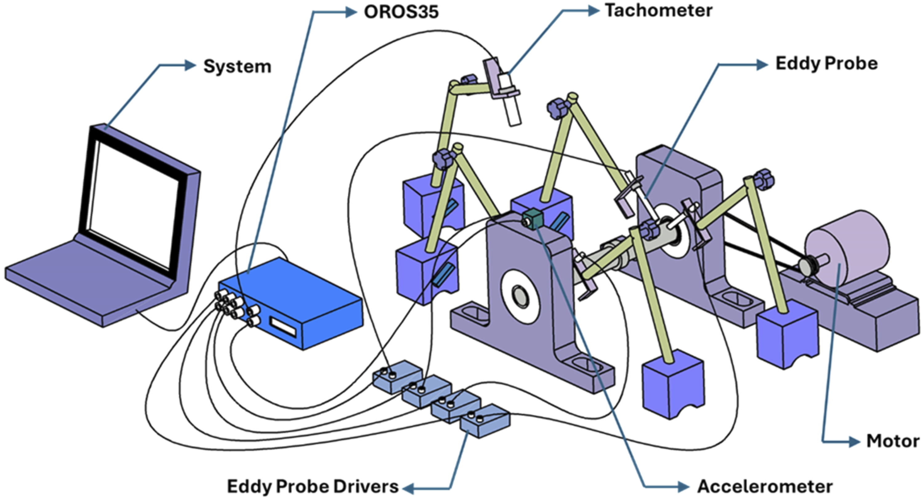
An in-house test rig was fabricated for the free-run test to measure the vibration characteristics of the 170 mm length shaft supported by the fabricated bearings. The bearing was mounted on the pillow blacks which are separated by 116 mm. The setup comprised the OR35-INST, a 6-channel DAQ system i e integrated with ORBI gate and NV-gate software. This software is responsible for handling the recording and post-analysis of the signals captured during the test using a PC system. Additionally, a 1-axis ORAC-DCC-D23 accelerometer and ORAC-TACMM-001 optical tachometer were used to gauge the vibration signals and the speed of the shaft. Eddy probe sensors (MTN/EP080) were used to measure the orbit and shaft centreline plots. These non-contact type sensors were placed in two sets, one just beside the bearing mounted near the motor and the other away from the motor with the support of stands. The mild steel shaft mounted on PTFE/CR25 bearings (Figure 3) was rotated continuously for 2 million cycles. The vibration signals and speed were recorded in the PC using the DAQ system. Bearings were fitted on the shaft and then fixed on the pillow block. Further, one end of the shaft was attached to the motor through a belt and pulley mechanism, and the accelerometer was attached to the pillow block, positioned far from the motor, to measure the vibration signals generated during the operation. The actual set-up and its schematic view are shown in Figures 4 and 5 respectively. CR25 bearings fitted on the shaft. Schematic representation of the free-run test rig. Free-run test rig.

Rolling contact fatigue test
The load-carrying capacity of PTFE and CR25 bearings is determined through an RCF test. The bearing was rotated at 800 RPM and subjected to a radial load from 25 to 75 N with a 25 N step. These parameters are like the testing parameters of part 1. But as per the lever rule (as shown in Figure 7), the actual radial force on the bearing is approximately 36 N to 108 N with step loading of 36 N. Initially, the bearing was loaded with 36 N for 0.25 million cycles, then with 72 N till 0.75 million cycles and with 108 N for the remaining cycles. The contact stresses generated between the rolling elements (subjected to maximum load) and the inner ring race for PTFE are 13.2 MPa, 16.6 MPa, and 19 MPa, respectively. In comparison, the corresponding stresses for CR25 are recorded as 28.8 MPa, 36.3 MPa, and 41.6 MPa. The schematic and typical setup for the RCF test are shown in Figures 6 and 7 respectively. In the test rig, a 300 mm length shaft is supported on the SKF metal bearings fixed in the pillow blocks. The test bearing is mounted on the shaft with the help of a bearing holder. A lever arm is attached to the bearing holder, and the load is applied to the other end of the lever. The accelerometer is mounted on the bearing holder’s top to record the vibration amplitudes generated during the test. After the completion of the test, the bearing races were analysed through the FEI-Apreo-S field emission scanning electron microscope (FESEM) and bearing race tracing was done through Mitutoyo MV-2100 Contracer. Schematic representation of RCF test rig. Typical setup of RCF test.

Results and discussion
Free run test
In the free-run test, RPM and vibrational amplitudes of the shaft were recorded, as shown in Figure 8(a)–(d). The shaft was initially rotated at 800 RPM for 1 million cycles on a PTFE and CR25 bearings sets. The shaft has shown a stable RPM during the run for both bearing sets. However, in PTFE bearings, a certain peak amplitude was recorded, which may be due to the wearing of the bearings. Further, in the CR25 bearings, the amplitude values were minimal, and no sudden rise in the amplitude was noted. The one million run results show that the CR25 bearing has better vibrational stability than PTFE. Since results obtained during the 1 million were favourable, the shaft was meant to rotate for another million cycles but at a higher RPM, i.e. 1000 RPM. Results show that both bearing sets have obtained similar results. The RPM was stable throughout, the vibrational amplitude was minimal, and no abruption in the system vibration has been noted. Overall, both bearing sets have shown excellent stability under minimal load conditions. However, the vibration signal amplitude for PTFE was lower than the first 1 million runs because PTFE tends to transfer the film to its counterpart. Continuous runs may cause the film to transfer more effectively, which leads to lower vibration amplitudes. In the case of CR25, the vibration amplitude remains consistent, showing that the carbon reinforcement in the PTFE matrix has improved the bearing performace. Free-run test results with respect to the number of cycles: PTFE. (a) RPM. (b) Amplitude; CR25. (c) RPM. (d) Amplitude.
Moreover, after the completion of each million cycles, the mass of the bearing was noted, which is mentioned in Table 1. The mass loss in the PTFE bearing during the initial 1 million cycles is more than the next million cycles for all bearing positions. About 2.17% mass loss in the bearing placed far from the motor and about 0.9% mass loss for the next million cycles. In the CR25 bearing, there was a minimal mass loss after completing 1 and 2 million runs. It was noted that the bearing at both positions showed a mass loss of less than 0.4% which shows that the reinforcement of the carbon becomes the barrier to resist the PTFE fragmentation. The mass loss in the bearing was primarily due to removing the machine marks formed during the bearing fabrication.
After the completion of 1 million cycles, the vibration dynamic characteristics were record with the help of eddy probe sensors along with the DAQ system. In this analysis, the shaft supported on bearings was rotated from 0 to 1000 RPM with an increment of 10 RPM per sec. The orbit and shaft centreline plots were obtained with the help of the DAQ system and computer. The shaft centreline and orbit plots are shown in Figures 9(a)–(d) and 10(a)–(d), respectively. These plots show the real-time displacement of the shaft at a particular RPM, which is one of the important characteristics to determine unbalance and misalignment in the shaft mounted of bearings. In the XY plane, the shaft centerline shows the displacement of the shaft centre from its mean position, and the orbit plot represents the position of the shaft centre in one rotation. The shaft centerline results show a very minimal displacement of the shaft centre in the X and Y directions, which shows negligible misalignment in the setup. Additionally, the orbit plots obtained are elliptical in shape, showing the shaft’s normal rotation. The elliptical shape may be due to less stiffness in the bearing. The vibration signals and rotor dynamics plots obtained during the free run test indicate that the bearings function properly. Shaft centreline plots, PTFE bearing (a) far from the motor, (b) near the motor; CR25 bearing (c) far from the motor (d) near the motor. Orbit plots at 1000 RPM, PTFE bearing (a) far from the motor, (b) near the motor; CR25 bearing (c) far from the motor (d) near the motor.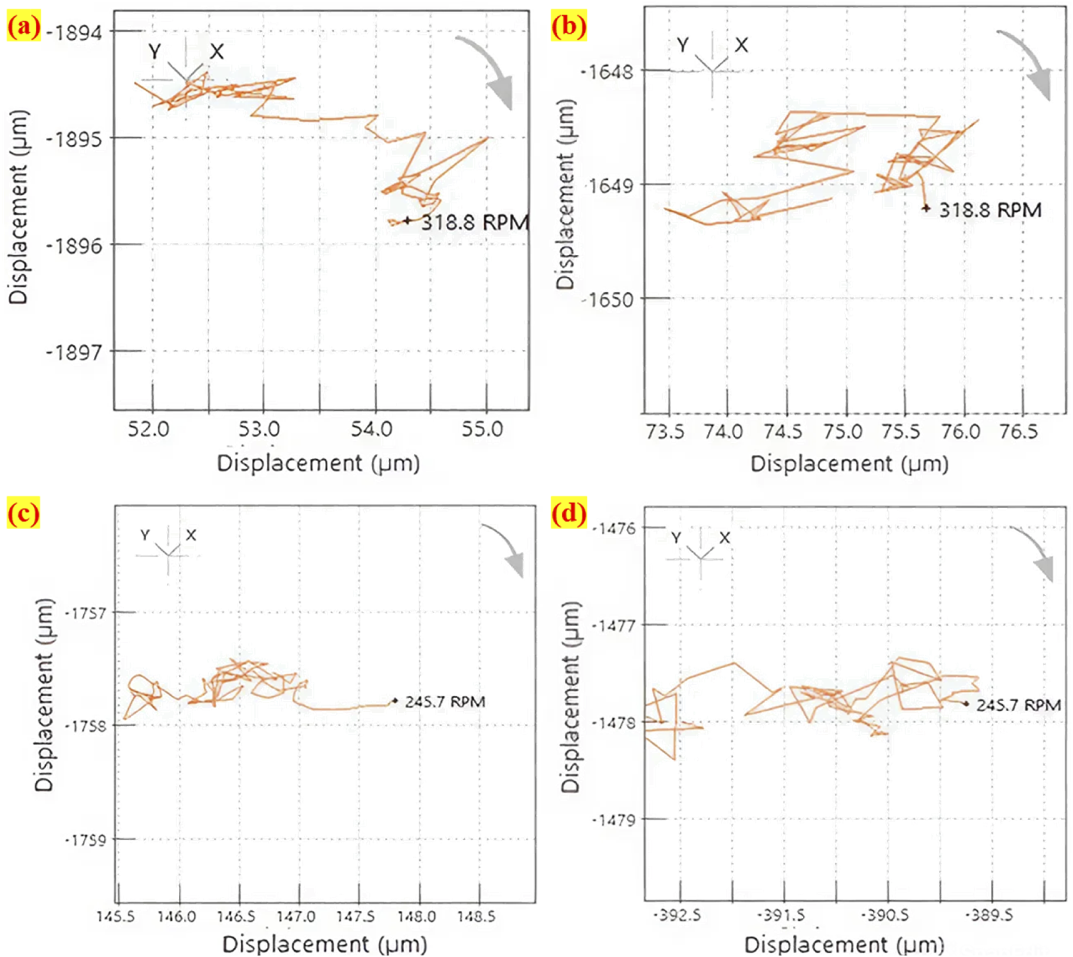

Overall, the characteristics of PTFE and CR25 DGB bearings for 2 million runs reveal that the vibration amplitude is relatively low for both bearings, particularly the CR25 bearing, which shows that the reinforcement significantly improves the bearing performance of the PTFE by improving its wear resistance. Further, the orbit and shaft centreline plot show that there is no misalignment and fault in the bearings after the rotation of 1 million cycles.
Rolling contact fatigue test
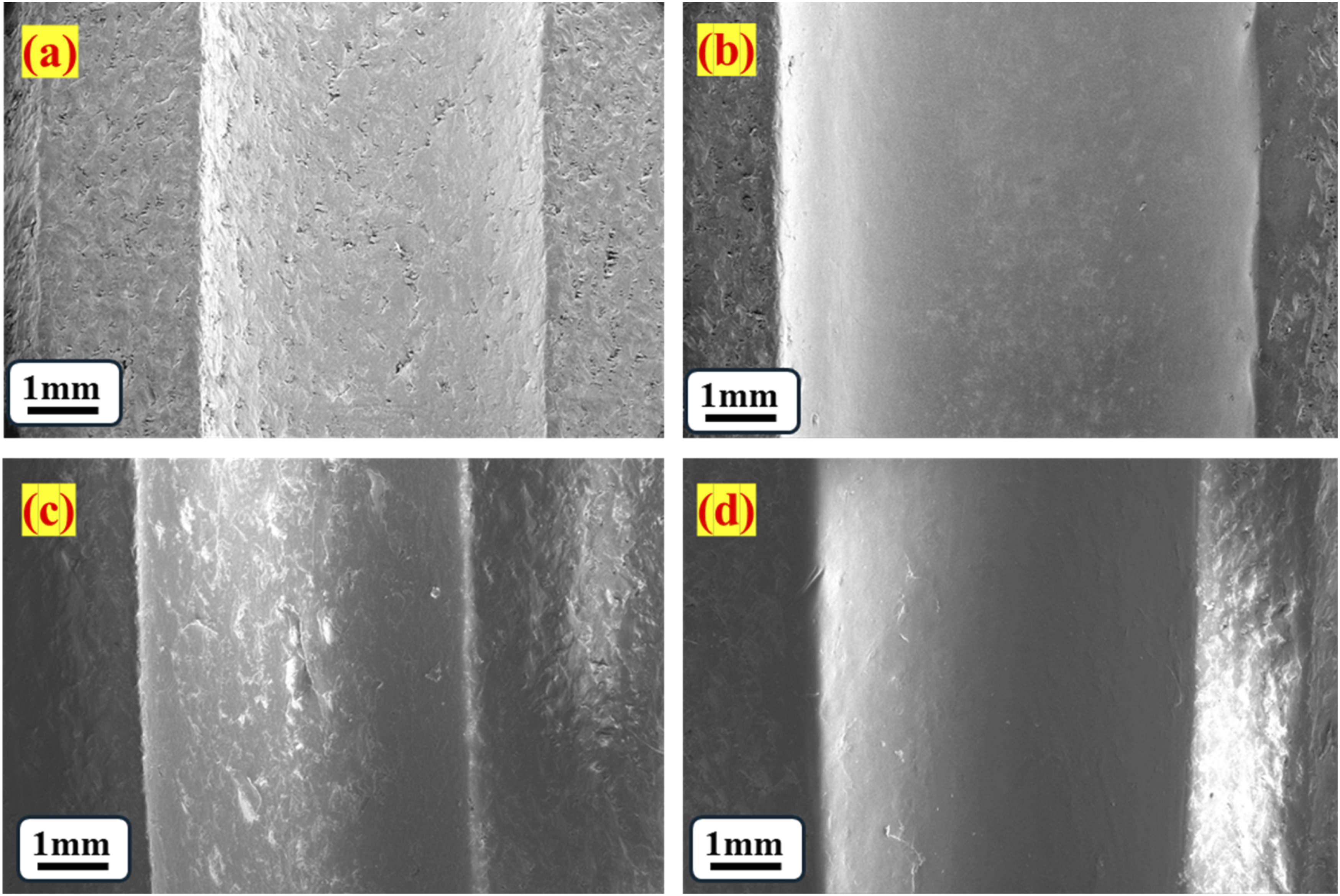
Initially, the PTFE bearing was subjected to load as the procedure mentioned in section 3.2 and its corresponding results are shown in Figure 11(a)–(d). The PTFE bearing has sustained a load of 36 N till 0.25 million cycles, and no abruption was noted in the amplitude and RPM signal. Later, when the load increased to 72 N, an undesirable rising pattern of vibration amplitude was noted (Figure 11(b)). Then, the bearing was demounted from the test rig, and a gap between the inner and outer race was noticed, and the bearing was declared failed. During the test, mass loss was around 1.14% with reference to its original weight (Table 2). Then, the CR25 bearing was subjected to the loading. However, the CR25 bearing could sustain 36 N till 0.25 million cycles and 72 N for the next 0.50 million cycles. When it was loaded with 108 N load, it failed at 0.88 million cycles. The failure in the bearing was noted through the instability in the RPM signals, as can be seen in Figure 11(c), which indicates that there is instability in the bearing, which reports that the bearing has failed. The mass loss for the CR25 bearing was less than 1% (Table 2). Both bearing failures were caused by widening the inner ring’s bearing race. To investigate the cause of failure further, the surface morphology of the bearing races of the inner and outer rings was analyzed through FESEM before and after the completion of the test, as shown in Figure 12(a)–(d) and 13(a)–(d). In the PTFE bearing, the races of both the outer and inner rings have machine marks, which may likely form during the fabrication process. Following the completion of the tests, these surfaces became notably smoother, and it was evident that wear had occurred. Further, there were no visible signs of cracking or surface erosion. In contrast, the CR25 bearing races (both inner and outer) also became smooth after testing, yet the ploughing patches remained evident, possibly resulting from hard carbon particles. However, the SEM images show that the failure’s primary cause is the widening of bearing races. This widening of the bearing is mainly due to the deformation of the bearing race, which has been caused due to the high hardness of Si3N4. The bearing race width measurements were taken using FESEM before and after testing. It has been noted that the outer ring race widths for PTFE and CR25 exhibited limited widening, with 2.7% and 4.81% increments, respectively. The race of the inner ring has experienced an increase of 18.68% for PTFE bearings and 26.03% for CR25 bearings. RCF results versus number of cycles. PTFE. (a) RPM, (b) acceleration; CR25. (c) RPM, (d) acceleration. Mass loss in bearings after the RCF test. Images of inner and outer races of the PTFE bearings. (a) Inner ring race before the test. (b) Inner ring race after the test. (c) Outer ring race before the test. (d) Outer race after the test. Images of inner and outer races of the CR25 bearings. (a) Inner ring race before failure. (b) Inner ring race after the test. (c) Outer ring race before failure. (d) Outer race after the test.


Utilizing the Contracer, the profile of the bearing race was mapped, which provided insight into the penetration depth caused by the bearing balls, as shown in Figure 14(a)–(h). It was observed that the depth of penetration was considerable in the inner ring races of both bearings. Specifically, there was a 31% increase in the depth of the PTFE bearing’s inner ring race, whereas the CR25 bearing exhibited a significant rise of 46%. In contrast, the outer ring race of the CR25 bearing showed only a marginal increase of about 2.8%, while the PTFE bearing experienced an 18% increase. These findings clearly indicate that the primary cause of bearing failure is due to deformation, which resulted in the widening of the bearing races. For the PTFE bearings, both the inner and outer ring races have undergone deformation to a certain extent, while in the case of CR25 bearings, the most significant deformation has been noted in the inner ring race. Overall, there was no sudden failure in the bearings, and it was easily detected through amplitude and RPM signals. Furthermore, there was no excessive heat generation in the bearing during the test because no burned patches or marks can be seen on the bearing race. This means the bearing design successfully eliminated the possibility of failure due to friction heat. Traced profile of bearing races. PTFE inner ring race (a) before the test. (b) After the test; PTFE outer ring race. (c) Before the test. (d) After the test; CR25 inner ring race. (e) Before the test. (f) After the test; CR25 outer ring race. (g) Before the test. (h) After the test.
Conclusion
This article focuses on using PTFE composites for deep groove ball-bearing applications. In this study, the PTFE and carbon-filled PTFE bearings were fabricated and tested through free run and RCF tests. The free-run test results show that both bearings showed excellent RPM stability, and the CR25 bearing recorded the best vibrational stability. However, a sudden rise in the vibration amplitudes was noted in the PTFE bearing, possibly due to the wear of the PTFE bearings. Further, the vibration dynamics characteristics, i.e., shaft centreline and orbit plot, were obtained at different times after completing one million cycles in the free run test. The results show no misalignment or defect in the bearing, and the rotor bearing system was stable. Hence, PTFE and CR25 bearings show excellent stability under minimal loading conditions. The radial load-carrying capacity of PTFE and CR25 configurations was measured through the RCF test. The PTFE failed at 0.26 million cycles under the load of 72 N, and CR25 failed at 0.88 million cycles under the load of 108 N. Therefore, the selected PTFE bearing configuration could be suitable for loads less than 36 N and CR25 for loads less than 72 N. The primary cause of bearing failure is the deformation of the bearing races, which causes the widening of the race because of the high hardness of Si3N4 balls. Frictional heat generated during the test was minimal, as no burns, patches, or marks were noted in the bearing after the test.
The tribological and bearing characterization shows that carbon-filled PTFE composite suits low load and low RPM applications. However, the usage of PTFE in the ball bearing application can be further improved by selecting the appropriate reinforcement content type and quantity in the PTFE matrix, which includes metal, ceramics, etc.
Footnotes
Acknowledgements
The authors acknowledge the support provided by BITS Pilani, Pilani Campus, and Manipal Institute of Technology, Manipal Academy of Higher Education, Manipal.
Author contribution
Dhruv Deshwal: Investigation, Data curation, Writing-original draft. Sachin U. Belgamwar: Methodology, Editing, Supervision. Siddappa I. Bekinal: Conceptualization and Design, Methodology, Resources, Editing, Supervision and Final approval. All authors have read and approved the final version of the manuscript.
Funding
The authors received no financial support for the research, authorship, and/or publication of this article.
Declaration of conflicting interests
The authors declared no potential conflicts of interest with respect to the research, authorship, and/or publication of this article.
Data Availability Statement
Data to support the findings of this study are available with the corresponding author and made available upon reasonable request.