
Abstract
Polytetrafluoroethylene (PTFE) is a self-lubricating, highly stable, high-performing polymer that has expanded its usage in bearing tribology. However, its application in ball bearings is still limited. This article explores using PTFE/carbon composites to evaluate their suitability for radial deep groove ball-bearing applications. The proposed work is divided into two parts. The first part focuses on the tribological characterization of the PTFE/carbon through a ball-on-disc test and examines the effect of reinforcement on bearing performance. The second part focuses on fabricating and analysing PTFE/carbon radial deep groove ball bearings for characteristics. In the first part, a ball-on-disc experiment was performed on pure PTFE (PTFE) and 25% carbon-filled PTFE (CR25) to measure the coefficient of friction (COF) and wear rate. These materials were subjected to three loading conditions at a particular speed using silicon nitride balls (Si3N4). The friction coefficient was recorded throughout the interaction, and specific wear rates were calculated. After completing the tests, wear tracks were analyzed using a scanning electron microscope and a Contracer.
Introduction
There is increasing interest in polymers and polymer composites as efficient alternatives to pure metals and hybrid materials. 1 Polymeric composites are popular in tribology for their lightweight, low wear and friction properties and better commercial usage. 2 Among different polymers, PTFE is an excellent tribological polymer for bearing applications.3,4 It is a high-performance polymer, a well-known engineering material developed for various industrial applications. Due to its self-lubricating properties,5,6 it is commonly used as a solid lubricant.7–9 Its long (CF2-CF2)n chains have low shear strength, leading to a low COF during sliding. 10 With excellent self-lubricating properties, 11 PTFE and its composites are used in several bearing applications, including seals, bearing cages, and sliding bearings.12–14 However, the high wear rate and lower mechanical strength are significant concerns in PTFE performance. Reinforcement of the appropriate filler material can improve its tribological properties. 15 The effect of reinforcement is not limited to improving the tribological properties but also enhances its mechanical strength and thermal properties.16–20 The filler materials are generally comprised of ceramics,12,21,22 metals,23–25 polymers,26–28 fibers,29–31 fabrics32,33 etc. Among all these, carbon-based material reinforcement is commonly used as the filler material in the PTFE, 34 which are CNT,35–37 graphene,38,39 carbon,40,41 carbon fibre42,43 etc. Carbon as a filler material has effectively improved the mechanical and tribological properties of the PTFE in the past. 44 Incorporating hard carbon materials significantly enhances the tribological properties of PTFE, resulting in a remarkable 15-fold increase in wear resistance. This enhancement can be attributed to the improved hardness and mechanical strength of the PTFE matrix. 45 However, the carbon reinforcement can lead to a slight increment in COF values during interaction. 46 The carbon-filled composites also show excellent thermal stability and wear performance in high temperatures. Sujuan and Xingrong 47 conducted a comprehensive study on the tribological performance of various PTFE composites at elevated temperatures, and the results reveal that carbon-filled PTFE exhibits exceptional wear resistance, demonstrating its effectiveness at ambient and elevated temperatures. Carbon-filled PTFE composites have been used in thrust-bearing applications. The findings of McCarthy and Glavatskih 48 show that carbon reduces PTFE wear in both dry and lubricated contacts, showcasing carbon’s high suitability as a filler material highly suitable for bearing applications.
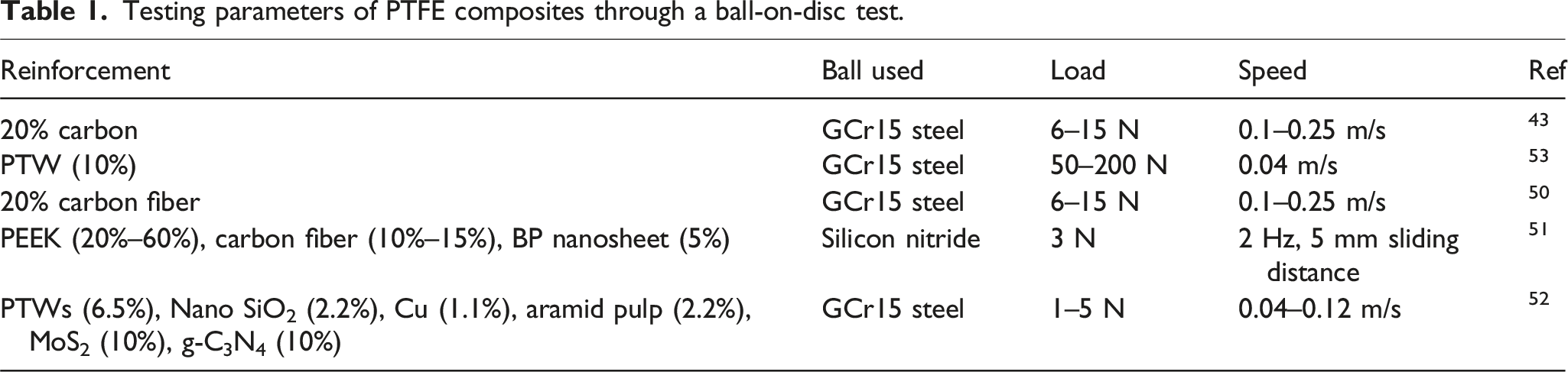
Testing parameters of PTFE composites through a ball-on-disc test.
Material and testing
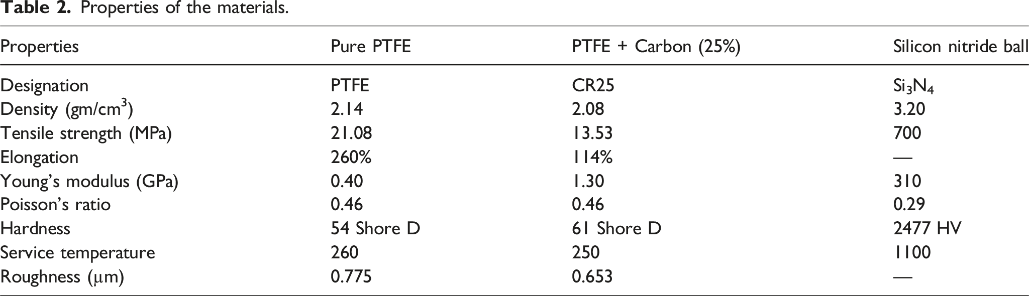
Properties of the materials.
The Ducom TR-20 Neo series friction and wear monitor was used to perform the ball-on-disc tribological test under dry conditions. Figure 1 shows the schematic arrangement of the test. The disc was rotated at the constant speed of 800 RPM and was subjected to loads of 25, 50, and 75 N. The contact pressure at the point of contact varies from 50 to 72 MPa for PTFE and 109 to 157 MPa for CR25. The ball was positioned at a wear track of 20 mm, and the tests were performed at room temperature with a relative humidity of 35% in dry conditions. After the completion of the test, the wear track formed on the disc was analysed through the FEI-Apreo-S field emission scanning electron microscope (FESEM) and wear track tracing was done through Mitutoyo MV-2100 Contracer. The formula used to calculate the specific wear rate is given in equation (1). Schematic diagram of the ball-on-disc test.

Results and discussion
Friction and wear results
The friction coefficients obtained at different loads for PTFE and CR25 are shown in Figure 2(a) and (b). In the case of PTFE, the COF values decrease as the load rises. This trend may be due to the effective transfer of the film on the ball as the load increases, which lowers the COF.
40
The average COF at 25 N is 0.159, which has decreased to 0.137 at 75 N, almost a 14% decrement (Figure 2(c)). However, in the case of CR25, the load does not affect the COF values and nearly remains the same, as seen in Figure 2(b). In the initial stage of interaction, there is a significant difference in the COF values, but later, after 200 m, the COF remains the same irrespective of the loads. The average COF for CR25 is slightly higher than that of PTFE. Furthermore, the results indicate that incorporating carbon reinforcement does not significantly alter the friction value. Notably, the reinforcement contributes to a tenfold improvement in wear resistance. This is due to the harder carbon, which acts as a barrier for PTFE to get fragmented.
46
The obtained specific wear rate values are plotted in Figure 2(d). The wear rate data indicates that as the load increased from 25 N to 75 N, there was a notable decrease in the specific wear rate. Specifically, the wear rate for PTFE decreased by 49%, while for CR25, the reduction was even more substantial by 89%. Overall, the results show that PTFE has a lower COF, and incorporating carbon has led to a slight increase in the COF value. However, adding carbon to PTFE enhances its wear resistance. Friction and wear results at different loading conditions (a) COF of PTFE, (b) COF of CR25, (c) average COF, (d) specific wear rate.
Wear track analysis
After measuring the friction and wear results, the wear track formed on the disc has been analyzed. The surface morphology was analysed through FESEM in all the loading conditions. The SEM images of PTFE and CR25 at different loading conditions are shown in Figures 3 and 4, respectively. Further, the wear track of all loading has been traced with the help of the Contracer. It helps to determine the approximate penetration of the Si3N4 ball during the test on the disc. The SEM image shows that PTFE has a smoother wear track. The tendency of PTFE to transfer its film to its counterpart results in a smoother wear track, which is associated with lower COF. In contrast, the analysis of CR25 reveals visible micro-ploughing and delamination of material across all loading conditions (refer to Figure 4(b)–(d)). This observation indicates a slightly rough wear track surface, indicating abrasive wear. This phenomenon may be attributed to the ineffective transfer of the film, potentially due to the presence of carbon. Wear track morphology of PTFE through SEM at different loads (a) 25 N, (b) 50 N, (c) 75 N. Wear track morphology of CR25 through SEM at different loads (a) 25 N, (b) 50 N, (c) 75 N.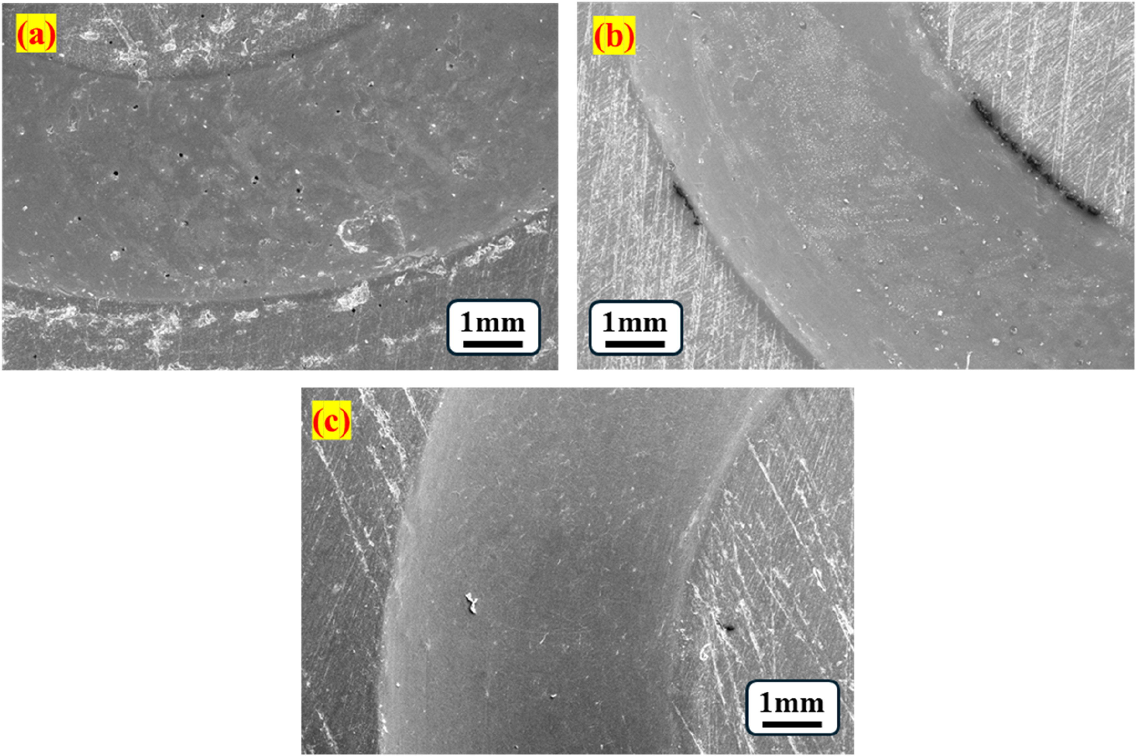

The profile obtained for PTFE through Contracer presents a smooth parabolic trajectory, as illustrated in Figure 5(a)–(c). In contrast, the profile traced for CR25 exhibits some irregularities, as depicted in Figure 5(d)–(f). This discrepancy may be attributed to micro ploughing, as evidenced by the FESEM images. Additionally, this unevenness could significantly contribute to the elevated COF values observed in CR25 compared to PTFE, potentially hindering the transfer of the film onto the counter ball. Wear track tracing through Contracer at 800 RPM under different loads. PTFE (a) 25 N, (b) 50 N, (c) 75 N; CR25, (d) 25 N, (e) 50 N, (f) 75 N.
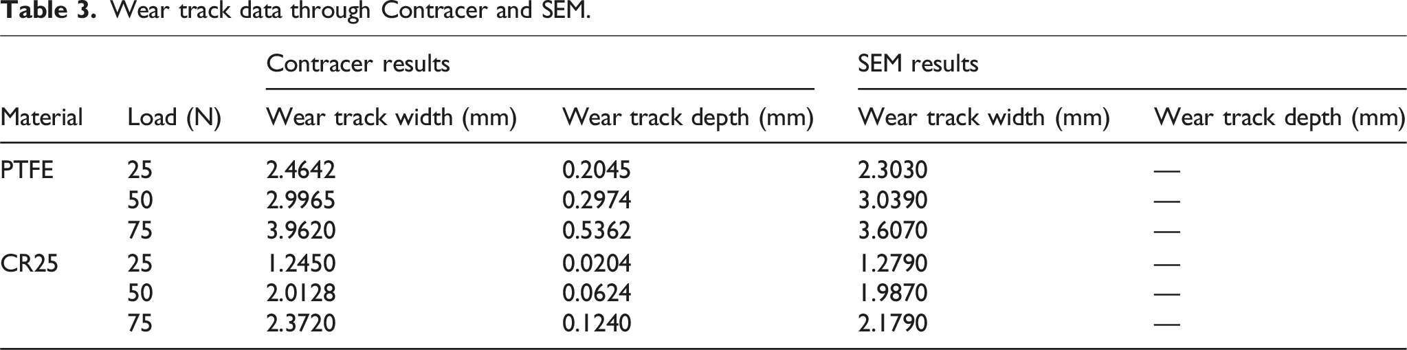
Wear track data through Contracer and SEM.
Conclusion
This article analysed the suitability of PTFE and CR25 composite for ball bearing application with Si3N4 balls through a ball-on disc test. Based on the results obtained, the following conclusions can be drawn: • Pure PTFE exhibits a low COF when interacting with Si3N4 balls with an average COF value of 0.15. However, it experiences significant wear during the test. Additionally, the wear track data indicates that the depth and width observed may not meet acceptable standards for the use in ball bearings. • CR25 has slightly higher COF in comparison to PTFE. However, it has shown almost 10 times more wear resistance than PTFE. The wear track data shows that depth and width values are nearly 50% less than the PTFE. • Overall, the results show that the carbon reinforcement in the PTFE has significantly improved tribological characteristics, and CR25 can be considered for ball-bearing applications. • In the second part of the paper, fabrication and testing of the PTFE/carbon composite radial deep groove ball bearings will be presented.
Footnotes
Acknowledgments
The authors acknowledge the support provided by BITS Pilani, Pilani Campus, and Manipal Institute of Technology, Manipal Academy of Higher Education, Manipal.
Author contributions
All authors have read and approved the final version of the manuscript.
Declaration of conflicting interests
The authors declared no potential conflicts of interest with respect to the research, authorship, and/or publication of this article.
Funding
The authors received no financial support for the research, authorship, and/or publication of this article.
Data availability statement
Data to support the findings of this study are available with the corresponding author and made available upon reasonable request.